analysis of heat transfer through different shape … · mahendergarh (hr) analysis of heat...
TRANSCRIPT

International Journal of Advances in Engineering & Scientific Research, Vol.2, Issue 5, May - 2015,
pp 19-38 ISSN: 2349 –3607 (Online) , ISSN: 2349 –4824 (Print)
Contact Us : [email protected] ; submit paper : [email protected] download full paper : www.arseam.com 19
www.arseam.com
ANALYSIS OF HEAT TRANSFER THROUGH
DIFFERENT SHAPE FINS USING CFD TOOL
Praveen Yadav
M.Tech Student
RPS Group of Institutions, Balana,
Mahendergarh (HR) – 123109
Rajender Singh Associate Professor
Department of Mechanical Engineering
RPS Group of Institutions, Balana,
Mahendergarh (HR) – 123109
Abstract:
This research presents the results of numerical study of heat transfer and pressure drop in a heat exchanger
that is designed with different shape fins. The heat exchanger used for this research consists of a rectangular duct fitted with
different shape fins (pin fins as well as thin plate fin), and is heated from the lower plate. The fin shape and the heat
exchanger (HE) configuration were numerically studied to maximize the convective heat transfer rate and minimize the
pressure drop across the heat exchanger & also along the heat sink. For analysis a three dimensional finite volume based
numerical model using CFD tool ANSYS FLUENT 14.0 was used. The simulation applied to estimate convection heat
transfer rate of fin surface and pressure drop in duct due to shape change at two different Reynolds number (Re 5000 &
50000) with different pin fins & a thin plate fin in turbulent forced convection conditions. Different fin configuration
includes tear drop, elliptical & rectangular cross section fins along with a thin rectangular plate fin, all having constant
total surface area and pin height ratio having different fin material has been studied. The data and conclusions of this study
can be applied to the optimization of different heat exchangers which are used in industry. It can also be used in the design
of Heat sink having internal fins, Charge air-cooler tubes with internal fins, vertical tubes & pipes & also for external fins of
air cooled I.C engines, compressors, electric motors, turbine blade cooling, space industry. The results obtained from the
different simulations shows that convective heat transfer rate increases with increase in Reynolds number. Hence turbulent
flow conditions of (Re=5000) are applied for the first simulation over all fin configurations & results shows that thin
rectangular plate fin dissipates maximum heat transfer rate & posses minimum pressure drop along duct geometry, this
result also represents that under less turbulent forced conditions thin plate fin is better than pin fins. While at much higher
Reynolds number (Re=50000) elliptical pin fins have the maximum heat transfer rate & even minimum pressure drop as
compared to all pin fin configurations. The research work also shows that material having higher thermal conductivity
posses higher convective heat transfer rate. Despite having the same total surface area thin rectangular plate fin has the
minimum volume which is beneficial from weight point of view.
Key words: CFD, FLUENT, Simulation, Optimization, Turbulence
1. Introduction
In Industries the thermal or heating problem is more common than domestics. So, there has been a great demand
for high performance, lightweight, compact & economical heat transfer components. Even the heat dissipation
medium is not enough for transformer of average and high power, which require more elaborated methods of
cooling and generated heat, must be removed effectively. The most popular enhancement is the fin. Fins are the
extended surfaces which are used to enhance the rate of heat transfer dissipation from heated surfaces to air. To
achieve better performance, conventionally, fins are added to plain tubes resulting in large external surface area
and high heat transfer performance and smaller dimensions. The common fins used extensively to increase the
rates of forced convection heat transfer from systems are rectangular & circular fins because such fins are
simple and cheap, to manufacture.

Praveen & Rajender / Analysis of Heat Transfer through Different Shape Fins Using CFD Tool
Contact Us : [email protected] ; submit paper : [email protected] download full paper : www.arseam.com 20
Fin technology has shown its excellent characteristic in heat transfer in electronics cooling and it seems that it’s
time to use this technology in conventional heat exchangers used in industrial application. The usage of this
technology in tubes will overcome the problems that other heat transfer enhancement tubes could not solved for
long time, i.e. large pressure loss and low total heat transfer efficiency. Its unique finned structure greatly
increases heat exchanging area both inside and outside the tube with dramatically reduced thickness of boundary
layers. The pin-fin tubes are widely used in the company's products, especially in heat exchangers (boilers,
radiators). Fins can either be long with H/D greater than about 10, or short with H/D on the order of unity.
Considering the negligible radiation heat transfer from fin Surface and one dimensional conduction through the
fin, the energy balance on a thin differential element is: The rate of heat conduction into the element = rate of
heat conduction out of element + rate of heat convection from the element surface.
In the present paper, a method has been suggested for optimizing tear drop pin-fin, elliptical pin-fin, thin
rectangular plate fin & rectangular pin-fin based on CFD.
2. Introduction to CFD
Computational fluid dynamics, abbreviated as CFD, is the science of predicting fluid, heat & mass transfer,
chemical reactions, and related phenomena by solving numerically the set of governing mathematical equations:
Conservation of mass
Conservation of momentum
Conservation of species
Effects of body forces
Computers are being used to do the calculations required to simulate the interaction of fluids with surfaces that
are defined by boundary conditions, and initial conditions. The Navier-Stokes equations form the basis of all
CFD problems. In case of CFD, the geometry of the problem is first made. Then the volume of the fluid is
quantified into discrete and definite cells which may be referred as the mesh. Then the modelling equations are
all set up, boundary conditions defined. The simulation is then done iteratively so that the solution converges to
a point. CFD may be used for both steady state and transient state analysis
3. Problem Description & Solution Procedure
Fig 3.1 Experimental setup of forced convection
This research is based on the problem of optimization of heat transfer from different shape fins (Pin-fins as well
as thin plate fin).Problem has three parts: 1.Base 2.Fin surface 3. Duct Solid Fin surface is mounted on the base
and it is established in the duct and Heat supplied to the fin base uniformly and it conducted through fin surface
and convected to the air which is flowing into the duct. Air is supplied by the blower at suitable velocity based

International Journal of Advances in Engineering & Scientific Research, Vol.2, Issue 5, May - 2015,
pp 19-38 ISSN: 2349 –3607 (Online) , ISSN: 2349 –4824 (Print)
Contact Us : [email protected] ; submit paper : [email protected] download full paper : www.arseam.com 21
on Reynolds No Most of the recent research has concentrated on rectangular & circular pin fins, probably
because they are easy to manufacture but, cylinders with elliptic shaped cross section & thin plate fin have lower
resistance to the flow and lower friction factor than the circular ones, as well as a higher surface wetted area that
can increase the heat transfer. This is shown in the presented study.
3.1 Model Description
In this research, four models are considered. The heat exchanger domain consists of three connected channels:
Entrance section, pin-fin section and exit section. The pin-fin section is composed of 6 solid pins that are
attached to Base which is considered as heat source. Three different pin shapes are considered: tear drop shape,
elliptical shape and rectangular shape. Other than these a thin plate fin along the whole Base length is also
simulated. Three different pin-fin morphologies along with a thin rectangular plate fin were investigated in this
primary study. The main geometrical dimensions that characterize the heat exchanger are the pin height (H), the
diameter of the cylindrical portion of the pin (D), for rectangular pin-fin & plate fin this parameter is considered
as fin width), for elliptical pin-fin the two dimensions along major & minor axes are considered as (A) & (B),
for rectangular plate fin the plate length is considered as (L), pin spacing (Δ).The total surface area is same for
all pin fins & plate fin. The entrance section of the heat exchanger is composed of a rectangular duct having
400mm as length, 50mm as width and 50mm as height. The pin fin section which consists of the base area is in
the middle having the length of 100 mm. The total surface area can easily be calculated from the following
formula:
Total surface area = areas of the top & bottom+ area of the side.
3.2 Fins’ geometry
The details of different pin-fins' morphologies are as follows:
The total surface area of all the fin geometries (pin fins & plate fin) is maintained as 2551mm2. H/D ratio is
constant for all fin geometries as 4.
All the Models are designed & generated by using software ANSYS FLUENT 14.0 or even it can also be
generated by using SOLIDWORKS software. After the geometry Boolean command is used to separate the
solid body (fin & base/bottom wall) because it can’t be a fluid. For less calculation & to mesh less, symmetry
along (YZ-Plane) is created & geometry is generated.
3.2.1 Tear drop pin-fin
Its cross section consists of a circular leading edge and a triangular trailing edge. Having the triangular portion
of the pin will help increase the wetted surface area of the heat exchanger leading to a major increase in the heat
transfer and the efficiency. In addition, it delays the separation in comparison with the circular cross section,
which helps decrease the friction factor and the flow resistance leading to a major decrease in the pressure loss.
The diameter (D) of the circular portion is 5 mm; height of the triangular trailing edge is 5 mm. Pin fin height
(H) is taken as 20 mm. The total surface area of the individual pin fin is taken as 425.16 mm2. Six drop shape
pin fins solid surfaces are mounted on the base which is in the middle of the rectangular duct section over a
length of 100 mm. Heat supplied to the fin base uniformly and it conducted through fin surface and convected to
the air which is flowing into the duct. Air is supplied by the blower at suitable velocity based on Reynolds No.

Praveen & Rajender / Analysis of Heat Transfer through Different Shape Fins Using CFD Tool
Contact Us : [email protected] ; submit paper : [email protected] download full paper : www.arseam.com 22
Fig 3.2 Drop-shaped pin-fin configurations
Fig 3.3 Computational domain of experimental setup
Tetrahedral meshing is generated & the element size is taken as 5 mm & relevance centre is made fine. Figure
3.4 shows the meshing of the complete geometry (solid as well as fluid).
Fig 3.4 Meshing of overall tear drop fin geometry with named selection

International Journal of Advances in Engineering & Scientific Research, Vol.2, Issue 5, May - 2015,
pp 19-38 ISSN: 2349 –3607 (Online) , ISSN: 2349 –4824 (Print)
Contact Us : [email protected] ; submit paper : [email protected] download full paper : www.arseam.com 23
3.2.2 Elliptical pin-fin
The elliptical cross section of each fin having major & minor axis dimension (A)=7mm & (B)=4.92mm. Height
(H) of the elliptical fin is 19.38mm. Total surface area of a single elliptical pin fin is 425.16mm2.Total surface
area of all elliptical pin fins is 2551mm2. Each elliptical pin fin is separated by 11.6mm. H/B ratio is maintained
constant as 4. Six elliptical shape pin fins solid surfaces are mounted on the base which is in the middle of the
rectangular duct section over a length of 100 mm. Heat supplied to the fin base uniformly and it conducted
through fin surface and convected to the air which is flowing into the duct. Air is supplied by the blower at
suitable velocity based on Reynolds No.
Fig 3.5 Elliptical shaped pin-fin configurations
Fig 3.6 Computational domain of experimental setup of elliptical pin fin
Fig 3.7 Meshing of overall elliptical fin geometry with named selection

Praveen & Rajender / Analysis of Heat Transfer through Different Shape Fins Using CFD Tool
Contact Us : [email protected] ; submit paper : [email protected] download full paper : www.arseam.com 24
3.2.3 Thin Rectangular plate fin
A thin rectangular plate having thickness/width(D) 2.5mm only, having length(L) & height(H) as 100mm &
10mm respectively. H/D ratio is maintained constant as 4. Total surface area of the plate fin surface is
2551mm2. Rectangular plate fin solid surface is mounted on the base which is in the middle of the rectangular
duct section over a length of 100 mm. Heat supplied to the fin base uniformly and it conducted through fin
surface and convected to the air which is flowing into the duct. Air is supplied by the blower at suitable velocity
based on Reynolds No.
Fig 3.8 Thin rectangular plate fin symmetrical geometry
Fig 3.9 Computational domain of experimental setup for thin plate fin
Fig 3.10 Meshing of overall plate fin geometry with named selection

International Journal of Advances in Engineering & Scientific Research, Vol.2, Issue 5, May - 2015,
pp 19-38 ISSN: 2349 –3607 (Online) , ISSN: 2349 –4824 (Print)
Contact Us : [email protected] ; submit paper : [email protected] download full paper : www.arseam.com 25
3.2.4 Rectangular pin-fin
The rectangular cross section of each fin having width (D) of 5mm,length 4.5mm, Height (H) of the rectangular
fin is 20mm. Total surface area of a single rectangular pin fin is 425.16mm2.Total surface area of all rectangular
pin fins is 2551mm2. Each rectangular pin fin is separated by 14.6mm. H/B ratio is maintained constant as 4. Six
rectangular pin fins solid surfaces are mounted on the base which is in the middle of the rectangular duct section
over a length of 100 mm. Heat supplied to the fin base uniformly and it conducted through fin surface and
convected to the air which is flowing into the duct. Air is supplied by the blower at suitable velocity based on
Reynolds No.
Fig 3.11 Rectangular shaped pin-fin configurations
Fig 3.12 Computational domain of experimental setup for thin plate fin
Fig 3.13 Meshing of overall rectangular fin geometry with named selection

Praveen & Rajender / Analysis of Heat Transfer through Different Shape Fins Using CFD Tool
Contact Us : [email protected] ; submit paper : [email protected] download full paper : www.arseam.com 26
Mesh (Grid) Generation and Nomenclature
Meshing is done to divide the domain (complete body) so that we can get a better result at each & every point.
Named selection is given at required parts of the geometry so as to define the boundary conditions & to check
the results at desired part of the geometry. For named selection inlet portion of the duct where velocity will be
defined as Velocity-inlet, Outlet of the rectangular duct is named as Pressure-outlet, heated bottom source
Where the temperature is to be defined is named as Base, fins surface area is named as Wall, Symmetric plane
along YZ is named as Symmetry & remaining complete body except solid body as Fluid.
In the problem setup section, click on the energy equation, it is required for all the fluid flow & thermal energy
problems. K-epsilon (2-eqn) model is selected because this model provides superior performance for flows
involving rotation, boundary layers under strong adverse pressure gradients, separation & recirculation.
Same boundary conditions & solution technique/method as defined in 3.4 & 3.5 are applied to solve all the
problems.
3.3 Boundary Condition
Inlet - The inlet air temperature will set to 290 K. The inlet velocity depends on the chosen Reynolds number
which is 5000 at a velocity of 1.5 m/s.Reynolds number is needed to be defined when we are dealing with
forced convection case. The hydraulic diameter is 50mm.
Outlet - The outlet boundary condition was set to out flow. The hydraulic diameter is 50mm.
Base/bottom wall - The bottom wall is kept at a constant temperature of 500 K. Since it is a rigid boundary the
no slip condition was applied leading to a zero velocity in the 3 directions, Ux=Uy=Uz=0. Material of the
bottom wall /Base is Nickel.
Fins - Convective heat transfer for the air is taken as 30W/m2-k because this is the case of forced convection of
gases.Material of the Pin-fins & Plate-fin is copper for one simulation & aluminium for other simulation to
check for the better results of convective heat transfer because copper has better thermal conductivity &
aluminium is light in weight. Free stream temperature is set at 290K.
3.4 Solution Technique (method)
All flows were specified as steady state and incompressible. The realizable k-e turbulence model with standard
wall function was set for each model. The Segregated 3D solver with an implicit formulation was set to solve
the model.Green gauss node based spatial discritization (meshing) is used because it is a case of tetrahedral
meshing. Residual convergence criteria is selected as none.Initialization is done so that the residual (difference
between values of iterations) can be stopped at last minimum value & number of iterations are defined to run
calculations.
4. Results and Discussions
4.1 Introduction
Upon completion of all the test runs, several key performance indicators were examined to understand the heat
transfer characteristics and trends for each pin-fin configuration with different Reynolds numbers. Analysis has
been done on four tubes of same dimensions but having different fin configuration or fin profile with same fin
height to width ratio. At first tear drop pin-fin in rectangular duct has been conidered, after that elliptical pin-fin,
thin rectangular plate fin & rectangular pin-fin results have been considered.Several checks were performed in
order to verify the generated results.The contour plots for velocity,temperature,pressure & nusselt number
alongwith XY plots of pressure & temperature variation were observed separately to ensure that the results
International Journal of Advances in Engineering & Scientific Research, Vol.2, Issue 5, May - 2015,
pp 19-38 ISSN: 2349 –3607 (Online) , ISSN: 2349 –4824 (Print)
Contact Us : [email protected] ; submit paper : [email protected] download full paper : www.arseam.com 27
satisfy the boundary conditions.The total convective heat transfer of wall(fin) is computed in the result
section.The result file is generated by Fluent upon completion of each run was carefully examined and analyzed.
4.2 Heat transfer
As previously stated, pin-fins have been introduced in the planar duct in order to enhance overall heat transfer
performance. The pins improve heat transfer rate due to the addition of their own surface area, and also by
increasing flow turbulence levels, thereby giving rise to better transport rates. In the current section, results for
5000 & 50000 Reynolds number are presented. It implies both are turbulent flow regime. To understand results
we study Temperature based results in graphical mode, Velocity results,Pressure based result & total convective
heat transfer rate of fin surface (wall).
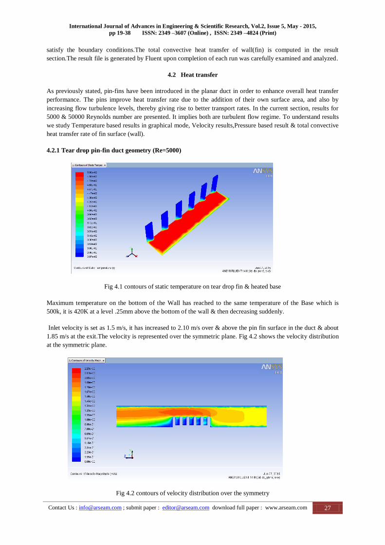
4.2.1 Tear drop pin-fin duct geometry (Re=5000)
Fig 4.1 contours of static temperature on tear drop fin & heated base
Maximum temperature on the bottom of the Wall has reached to the same temperature of the Base which is
500k, it is 420K at a level .25mm above the bottom of the wall & then decreasing suddenly.
Inlet velocity is set as 1.5 m/s, it has increased to 2.10 m/s over & above the pin fin surface in the duct & about
1.85 m/s at the exit.The velocity is represented over the symmetric plane. Fig 4.2 shows the velocity distribution
at the symmetric plane.
Fig 4.2 contours of velocity distribution over the symmetry

Praveen & Rajender / Analysis of Heat Transfer through Different Shape Fins Using CFD Tool
Contact Us : [email protected] ; submit paper : [email protected] download full paper : www.arseam.com 28
Now the primary problem in fin designing which must be ovecome is low convective heat transfer rate, so
its most important point is to compute convection heat transfer rate from the Wall & for tear drop pin fin
surface, the computed result displayed by ANSYS FLUENT 14.0 under the boundary conditions defined in
chapter 3 is as follows:
So, the total convective heat transfer rate by tear drop pin fins computed by ANSYS FLUENT software under
defined boundary conditions is -0.23663848 w.
Another major problem is large pressure loss in the usage of this technology in the tubes, so it is important to
find out the total pressure loss in the duct. Pressure drop is a term used to describe the differential pressure that
fluid must overcome to flow through a system. Pressure drop is a result of resistance caused by friction(shear
stress) or other forces (such as gravity) acting on a fluid.Total pressure is the pressure a fluid exerts as it is
brought to a stop. X-Y Plot in fig 4.3, provides us the exact information about total pressure at the inlet, outlet
section of the rectangular duct & the total pressure loss/drop.The figure 4.3 illustrates that the total pressure at
the inlet of the duct is 2.60 pascal & the minimum total pressure at the outlet is 0.60 pascal, so the total pressure
loss/drop in the rectangular duct is 2.00 pascal.In most cases minimum pressure drop through a system is
desirable, pressure drop can be minimised by removing the kinks, avoiding long hoses & by choosing optimum
kink surface.
Fig 4.3 XY Plot representing total pressure at inlet & outlet section of duct
If the fin material is aluminium rather than copper in the pin-fin duct section than the total heat transfer by
convection is -0.23683263 w.

International Journal of Advances in Engineering & Scientific Research, Vol.2, Issue 5, May - 2015,
pp 19-38 ISSN: 2349 –3607 (Online) , ISSN: 2349 –4824 (Print)
Contact Us : [email protected] ; submit paper : [email protected] download full paper : www.arseam.com 29
The results shows that the fin material which has higher thermal conductivity has more heat dissipation by
convection, despite the fact that aluminium is lighter in weight but due to higher thermal conductivity copper
has higher heat dissipation rate by convection which comes out to be -0.23663848 w, hence copper is a better
material for convective heat transfer rate as using fin material.
The purpose behind using 5000 Reynolds No. Is that in case of laminar flow using Re as 2000 the total heat
tranfer by convection from the copper fin surface is -0.2943198 w, which shows that we should go for much
higher Reynolds No.
5.2.2 Tear drop pin-fin duct geometry (Re=50000)
Here Inlet velocity is set as 15 m/s, it has increased to 19 m/s in pin fin section of the duct & about 16 m/s at the
exit.The velocity is represented over the symmetric plane un figure 4.4
Fig 4.4 contours of velocity distribution over the symmetry
Now the primary problem of total convection heat transfer rate as computed by ANSYS FLUENT 14.0
under the boundary conditions defined in chapter 4 with Re 50000 for tear drop pin fin surface is as follows:
Fig 4.5 XY Plot representing total pressure at inlet & outlet section of duct

Praveen & Rajender / Analysis of Heat Transfer through Different Shape Fins Using CFD Tool
Contact Us : [email protected] ; submit paper : [email protected] download full paper : www.arseam.com 30
Total pressure at the inlet of duct is 198 pascal & minimum total pressure at the outlet is 70 pascal, so the total
pressure drop in rectangular duct is 128 pascal.
5.2.3 Elliptical pin-fin duct geometry (Re=5000)
Fig 4.6 contours of static temperature on elliptical pin fin & heated base
Maximum temperature on the bottom of the Wall(mainly by conduction) has reached to 452K, it is 333K at a
level 1mm above the bottom of the wall & then decreasing suddenly. Inlet velocity of 1.5 m/s has increased to
2.15 m/s in the pin fin section in the duct & about 1.80 m/s at the exit.The velocity is represented over the
symmetric plane in fig 4.7
Fig 4.7 contours of velocity distribution over the symmetry
Convection heat transfer rate from the from elliptical pin fin surface(wall) , the computed result displayed by
ANSYS FLUENT 14.0 under the boundary conditions defined in chapter 3 is as follows:
So, the total convective heat transfer rate by elliptical pin fins computed by ANSYS FLUENT software under
defined boundary conditions is -0.20287238 w.

International Journal of Advances in Engineering & Scientific Research, Vol.2, Issue 5, May - 2015,
pp 19-38 ISSN: 2349 –3607 (Online) , ISSN: 2349 –4824 (Print)
Contact Us : [email protected] ; submit paper : [email protected] download full paper : www.arseam.com 31
Higher Nusselt number represents higher heat dissipation by convection as compared to heat generated by
conduction. Here at one elliptical pin fin the Nu has reached even upto 2530.
Fig 4.8 XY Plot representing total pressure at inlet & outlet section of duct
The figure 4.8 illustrates that the total pressure at the inlet of the duct is 2.70 pascal & the minimum total
pressure at the outlet is 0.71 pascal, so the total pressure loss/drop in the rectangular duct is 1.99 pascal. The
reason is that in this configuration flow particles follow a smoother path line.
5.2.4 Elliptical pin-fin duct geometry (Re=50000)
For 50000 Reynolds No. Inlet velocity is set at 15 m/s, it has increased to 20 m/s over & above the pin fin
surface in the duct & about 17 m/s at the exit.The velocity is represented over the symmetry.
Fig 4.9 contours of velocity distribution over the symmetry
Total convection heat transfer rate as computed by ANSYS FLUENT 14.0 under the boundary conditions
defined in chapter 3 with Re 50000 for elliptical pin fin surface is as follows:

Praveen & Rajender / Analysis of Heat Transfer through Different Shape Fins Using CFD Tool
Contact Us : [email protected] ; submit paper : [email protected] download full paper : www.arseam.com 32
The total convective heat transfer rate by tear drop pin fins computed by ANSYS FLUENT software under
defined boundary conditions is 0.0016956513 w. This is the maximum convective heat dissipation rate by any
fin geometry among cosidered Re.
Fig 4.10 XY Plot representing total pressure at inlet & outlet section of duct
Total pressure at the inlet of duct is 206 pascal & minimum total pressure at the outlet is 79 pascal, so the total
pressure drop in rectangular duct is 127 pascal.
5.2.5 Thin rectangular plate fin duct geometry (Re=5000)
Maximum temperature on the bottom of the Wall has reached to a temperature of 400k, it is 375K at a level
1mm above the bottom of the wall & then decreasing linearly.
Fig 4.11 contours of static temperature on rectangular plate fin & heated base
For 5000 Reynolds No. Inlet velocity is set at 1.5 m/s, it has increased to 1.85 m/s in the pin fin section of the
duct & remains same at the exit.

International Journal of Advances in Engineering & Scientific Research, Vol.2, Issue 5, May - 2015,
pp 19-38 ISSN: 2349 –3607 (Online) , ISSN: 2349 –4824 (Print)
Contact Us : [email protected] ; submit paper : [email protected] download full paper : www.arseam.com 33
Fig 4.12 contours of velocity distribution over the symmetry
Convection heat transfer rate from the thin rectangular plate fin surface(Wall), the computed result displayed
by ANSYS FLUENT 14.0 under the boundary conditions defined in chapter 3 is as follows:
Hence, the total heat transfer rate by convection from thin rectangular plate fin computed by ANSYS FLUENT
software under defined boundary conditions is -0.1416964 w.
At about 30 percent of plate fin area the Nu is around 200 or more, which is a good indication of convective
heat transfer over conduction rate.
Fig 4.13 XY Plot representing total pressure at inlet & outlet section of duct
The total pressure at the inlet of the duct is 2.40 pascal & the minimum total pressure at the outlet is 0.80
pascal, so the total pressure loss/drop in the rectangular duct is 1.60 pascal. It is the least pressure drop as
compared to all pin fins.

Praveen & Rajender / Analysis of Heat Transfer through Different Shape Fins Using CFD Tool
Contact Us : [email protected] ; submit paper : [email protected] download full paper : www.arseam.com 34
5.2.6 Thin rectangular plate fin duct geometry (Re=50000)
For 50000 Reynolds No. Inlet velocity is set at 15 m/s, it has increased to 20 m/s over & above the pin fin
surface in the duct & about 17 m/s at the exit.
Fig 4.14 contours of velocity distribution over the symmetry
Total convection heat transfer rate as computed by ANSYS FLUENT 14.0 under the boundary conditions
defined in chapter 3 with Re 50000 for thin rectangular plate fin surface is as follows:
The results of the total pressure as generated by figure 4.15 shows that the total pressure at the inlet of duct is
182 pascal & minimum total pressure at the outlet is 88 pascal, so the total pressure drop in rectangular duct is
94 pascal. This is the minimum pressure drop for all considerd configurations including thin plate fin & pin-fins
at 50000 Re.
Fig 4.15 XY Plot representing total pressure at inlet & outlet section of duct

International Journal of Advances in Engineering & Scientific Research, Vol.2, Issue 5, May - 2015,
pp 19-38 ISSN: 2349 –3607 (Online) , ISSN: 2349 –4824 (Print)
Contact Us : [email protected] ; submit paper : [email protected] download full paper : www.arseam.com 35
5.2.7 Rectangular pin-fin duct geometry (Re=5000)
Fig 4.16 contours of static temperature on rectangular pin-fin & heated base
Maximum temperature on the bottom of the Wall has reached to 440K, it is around 320K at a level 5mm above
the bottom.Inlet velocity of 1.5 m/s has increased to 1.95 m/s in the pin fin section of the duct & is 1.80m/s at
exit.
Fig 4.17 contours of velocity distribution over the symmetry
Convection heat transfer rate from the Wall of rectangular pin fin surface as computed by ANSYS FLUENT
14.0 under the boundary conditions defined in chapter 3 for rectangular pin fins geometry is as follows:
So, the total convective heat transfer rate by rectangular pin fins computed by ANSYS FLUENT software
under defined boundary conditions is -0.30819158 w.

Praveen & Rajender / Analysis of Heat Transfer through Different Shape Fins Using CFD Tool
Contact Us : [email protected] ; submit paper : [email protected] download full paper : www.arseam.com 36
Fig 4.18 XY Plot representing total pressure at inlet & outlet section of duct
The total pressure at the inlet of the duct is 2.60 pascal & the minimum total pressure at the outlet is 0.60
pascal, so the total pressure loss/drop in the rectangular duct is 2.00 pascal. The total pressure drop of 2.00
pascal shown by rectangular pin fin is higher than elliptical pin fin case & rectangular plate fin section case.
5.2.8 Rectangular pin-fin duct geometry (Re=50000)
Fig 4.19 contours of velocity distribution over the symmetry
For 50000 Reynolds No. Inlet velocity is set at 15 m/s, it has increased to 20 m/s over & above the pin fin
surface in the duct & about 17 m/s at the exit.
Total convection heat transfer rate as computed by ANSYS FLUENT 14.0 under the boundary conditions
defined in chapter 3 with Re 50000 for elliptical pin fin surface is as follows:
International Journal of Advances in Engineering & Scientific Research, Vol.2, Issue 5, May - 2015,
pp 19-38 ISSN: 2349 –3607 (Online) , ISSN: 2349 –4824 (Print)
Contact Us : [email protected] ; submit paper : [email protected] download full paper : www.arseam.com 37
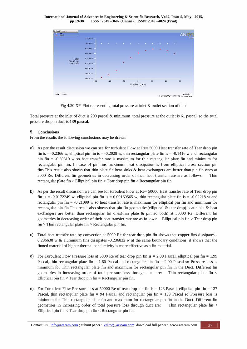
Fig 4.20 XY Plot representing total pressure at inlet & outlet section of duct
Total pressure at the inlet of duct is 200 pascal & minimum total pressure at the outlet is 61 pascal, so the total
pressure drop in duct is 139 pascal.
5. Conclusions
From the results the following conclusions may be drawn:
a) As per the result discussion we can see for turbulent Flow at Re= 5000 Heat transfer rate of Tear drop pin
fin is = -0.2366 w, elliptical pin fin is = -0.2028 w, thin rectangular plate fin is = -0.1416 w and rectangular
pin fin = -0.30819 w so heat transfer rate is maximum for thin rectangular plate fin and minimum for
rectangular pin fin. In case of pin fins maximum heat dissipation is from elliptical cross section pin
fins.This result also shows that thin plate fin heat sinks & heat exchangers are better than pin fin ones at
5000 Re. Different fin geometries in decreasing order of their heat transfer rate are as follows: Thin
rectangular plate fin > Elliptical pin fin > Tear drop pin fin > Rectangular pin fin.
b) As per the result discussion we can see for turbulent Flow at Re= 50000 Heat transfer rate of Tear drop pin
fin is = -0.0172249 w, elliptical pin fin is = 0.00169565 w, thin rectangular plate fin is = -0.02218 w and
rectangular pin fin = -0.21099 w so heat transfer rate is maximum for elliptical pin fin and minimum for
rectangular pin fin.This result also shows that pin fin geometries(elliptical & tear drop) heat sinks & heat
exchangers are better than rectangular fin ones(thin plate & pinned both) at 50000 Re. Different fin
geometries in decreasing order of their heat transfer rate are as follows: Elliptical pin fin > Tear drop pin
fin > Thin rectangular plate fin > Rectangular pin fin.
c) Total heat transfer rate by convection at 5000 Re for tear drop pin fin shows that copper fins dissipates -
0.236638 w & aluminium fins dissipates -0.236832 w at the same boundary conditions, it shows that the
finned material of higher thermal conductivity is more effective as a fin material.
d) For Turbulent Flow Pressure loss at 5000 Re of tear drop pin fin is = 2.00 Pascal, elliptical pin fin = 1.99
Pascal, thin rectangular plate fin = 1.60 Pascal and rectangular pin fin = 2.00 Pascal so Pressure loss is
minimum for Thin rectangular plate fin and maximum for rectangular pin fin in the Duct. Different fin
geometries in increasing order of total pressure loss through duct are: Thin rectangular plate fin <
Elliptical pin fin < Tear drop pin fin = Rectangular pin fin.
e) For Turbulent Flow Pressure loss at 50000 Re of tear drop pin fin is = 128 Pascal, elliptical pin fin = 127
Pascal, thin rectangular plate fin = 94 Pascal and rectangular pin fin = 139 Pascal so Pressure loss is
minimum for Thin rectangular plate fin and maximum for rectangular pin fin in the Duct. Different fin
geometries in increasing order of total pressure loss through duct are: Thin rectangular plate fin <
Elliptical pin fin < Tear drop pin fin < Rectangular pin fin.

Praveen & Rajender / Analysis of Heat Transfer through Different Shape Fins Using CFD Tool
Contact Us : [email protected] ; submit paper : [email protected] download full paper : www.arseam.com 38
f) With equal pin-fin surface area for all morphologies, the elliptical pins have the maximum volume which
increases the weight. This is another factor that should be considered for optimization. Thin rectangular
plate has the minimum weight, which is a benefit from weight point of view. The increasing order of
different fin arrangements according to their weight: Thin rectangular plate fin < Tear drop pin fin <
Rectangular pin fin < Circular pin fin < Elliptical pin fin.
g) In case of laminar flow using Re as 2000 the total heat tranfer by convection from the copper fin surface is -
0.2943198 w, convection heat transfer at 5000 Re in turbulant flow is -0.23683 w & at 50000 Re it is -
0.0172249 w. Turbulant flows can give rise to convective heat transfer rates which are much larger than
those of laminar flows, and are caused by the manner in which the turbulant fluctuations increases mixing.
h) Thin plate fin heat sinks posses the minimum pressure drop under all condition.
i) Out of all pin fins, elliptical pins showed best results, even better than tear drop shaped morphology.
j) The overall work concludes that fins enhance heat transfer from a surface by exposing large surface
area to convection. Under forced convection turbulent flow at 5000 Re thin rectangular plate fin is most
effective. This also shows that under these conditions thin plate fin is better than pin fins while at
much higher Reynolds number (Re=50000) , the use of elliptical pin fins is justified to overcome the
problems of low convection heat transfer rate & large pressure drop.
References
1. B. Moshfegh, R. Nyiredy, Comparing RANS Models for Flow and Thermal Analysis of Pin Fin Heat Sinks,
15th Australasian Fluid Mechanics Conference, the University of Sydney, Sydney, Australia 13-17
December 2004.
2. Christopher L. Chapman, Seri Lee, Bill L. Schmidt, Thermal Performance of an Elliptical Pin Fin Heat
Sink, Tenth IEEE Semi-Ther MPFeb. 2000.
3. Jihed Boulares , Numerical and Experimental Study of The Performance of a Drop-Shaped Pin Fin Heat
Exchanger, Master Research, NAVAL POSTGRADUATE SCHOOL Monterey, California, 2003.
4. Kröger, D.G, Performance characteristics of industrial finned tubes presented in dimensional form, Int.
Journal of Mass and Heat Transfer, vol. 29, no. 8, pp. 1119-1125, 1986
5. Mukesh Didwania, Gopal Krishan, Ravikant, Study and Analysis of Heat Transfer through Two Different
Shape Fins using CFD Tool.
6. Myhren J.A., Holmberg S., Improving the thermal performance of ventilation radiator-the role of internal
convective fins, International journal of heat and mass transfer, 2010, vol. 50, pg. 115-123
7. Nabati H., Mahmoudi J.,Numerical Study of Thermal Performance of Different Pin-Fin
Morphologies,46th Conference on Simulation and Modeling (SIMS 2005), Trondheim, Norway, 2005
8. Rustum, I.M. and Soliman, H.M., Experimental investigation of laminar mixed convection in tubes
with longitudinal fins, Journal of Heat Transfer, vol. 110, May, pp. 366-372, 1988.
9. Sanjay Kumar Sharma and Vikas Sharma, maximizing the heat transfer through fins using CFD Tool.
10. Sazali N., Experimental study of natural convection heat transfer in a vertical internally finned tube, 2009
11. Zhang, Y. and Faghri, A., Heat transfer enhancement in latent heat thermal energy storage system by using
the internally finned tube, Int. Journal of Mass and Heat Transfer, vol. 39, no. 15, pp. 3165-3173, 1996.