analysis of model based feedforward for motion systems · analysis of model based feedforward for...
TRANSCRIPT

Analysis of model based feedforward for motion systems
Boerlage, M.L.G.; Steinbuch, M.
Published: 01/01/2002
Document VersionPublisher’s PDF, also known as Version of Record (includes final page, issue and volume numbers)
Please check the document version of this publication:
• A submitted manuscript is the author's version of the article upon submission and before peer-review. There can be important differencesbetween the submitted version and the official published version of record. People interested in the research are advised to contact theauthor for the final version of the publication, or visit the DOI to the publisher's website.• The final author version and the galley proof are versions of the publication after peer review.• The final published version features the final layout of the paper including the volume, issue and page numbers.
Link to publication
General rightsCopyright and moral rights for the publications made accessible in the public portal are retained by the authors and/or other copyright ownersand it is a condition of accessing publications that users recognise and abide by the legal requirements associated with these rights.
• Users may download and print one copy of any publication from the public portal for the purpose of private study or research. • You may not further distribute the material or use it for any profit-making activity or commercial gain • You may freely distribute the URL identifying the publication in the public portal ?
Take down policyIf you believe that this document breaches copyright please contact us providing details, and we will remove access to the work immediatelyand investigate your claim.
Download date: 20. Aug. 2018

Analysis of model based feedforward for motion systems
M.L.G. Boerlage Report nr: DC2002.60
Supervisor: Prof. Dr. Ir. M. Steinbuch
1
ACC03-IEEE0319 Analysis of model based feedforward for motion systems
Matthijs Boerlage and Maarten Steinbuch Eindhoven University of Technology
Faculty of Mechanical Engineering, Control Systems Technology Group
P.O. Box 513, 5600 MB Eindhoven, The Netherlands
Email: [email protected]@tue.nl
Abstract- This paper considers model-based feedforward for motion systems. The proposed feedforward controller consists of an acceleration feedforward part and an inverse dynamics model of flexible modes. Based on analysis and H= model-based feedfoward design, the inverse dynamics part can be restricted to a second order filter in the form of a skew notch even if the motion system has more parasitic modes. The benefit of this is an on-line tuning possibility. Tracking errors and settling times can be reduced significantly, compared to acceleration feedforward.
I. INTRODUCTION
I N many today's motion systems, high performance requirements involve short motion times (and hence high acceler
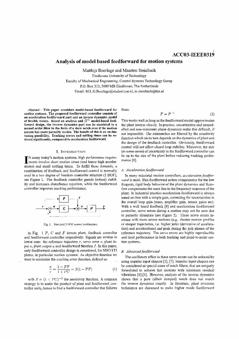
ations) and small settling times. To fulfill these demands, a combination of feedback and feedforward control is normally used in a two degree of freedom controller structure (2 DOF), see Figure 1. The feedback controller guards (robust) stability and increases disturbance rejection, while the feedforward controller improves tracking performance.
Fig. 1. Standard 2 DOF control architecture.
In Fig. 1 P, C and F denote plant, feedback controller and feedforward controller respectively. Signals are written in lower case: the reference trajectory r, servo error e, plant input u, plant output y and feedforward function f. In this paper, only feedforward controller design is considered, for SISO LTI plants, in particular motion systems. As objective function we want to minimize the tracking error function, defined as:
:::.=l-PF =S(1-PF) r l+PC
(1)
with S = (1 + pC)-l the sensitivity function. A common strategy is to make the product of plant and feedforward controller unity, hence to find a feedforward controller that follows
from: (2)
This works well as long as the feedforward model approximates the plant inverse closely. In practice, uncertainties and unmodelled and non-minimum phase dynamics make this difficult, if not impossible. The mismatches are filtered by the sensitivity function which on its tum depends on the dynamics of plant and the design of the feedback controller. Obviously, feedforward control will not affect closed loop stability. Moreover, the size (in some sense) of uncertainty in the feedforward controller can be up to the size of the plant before reducing tracking performance [1].
A. Acceleration feedforward
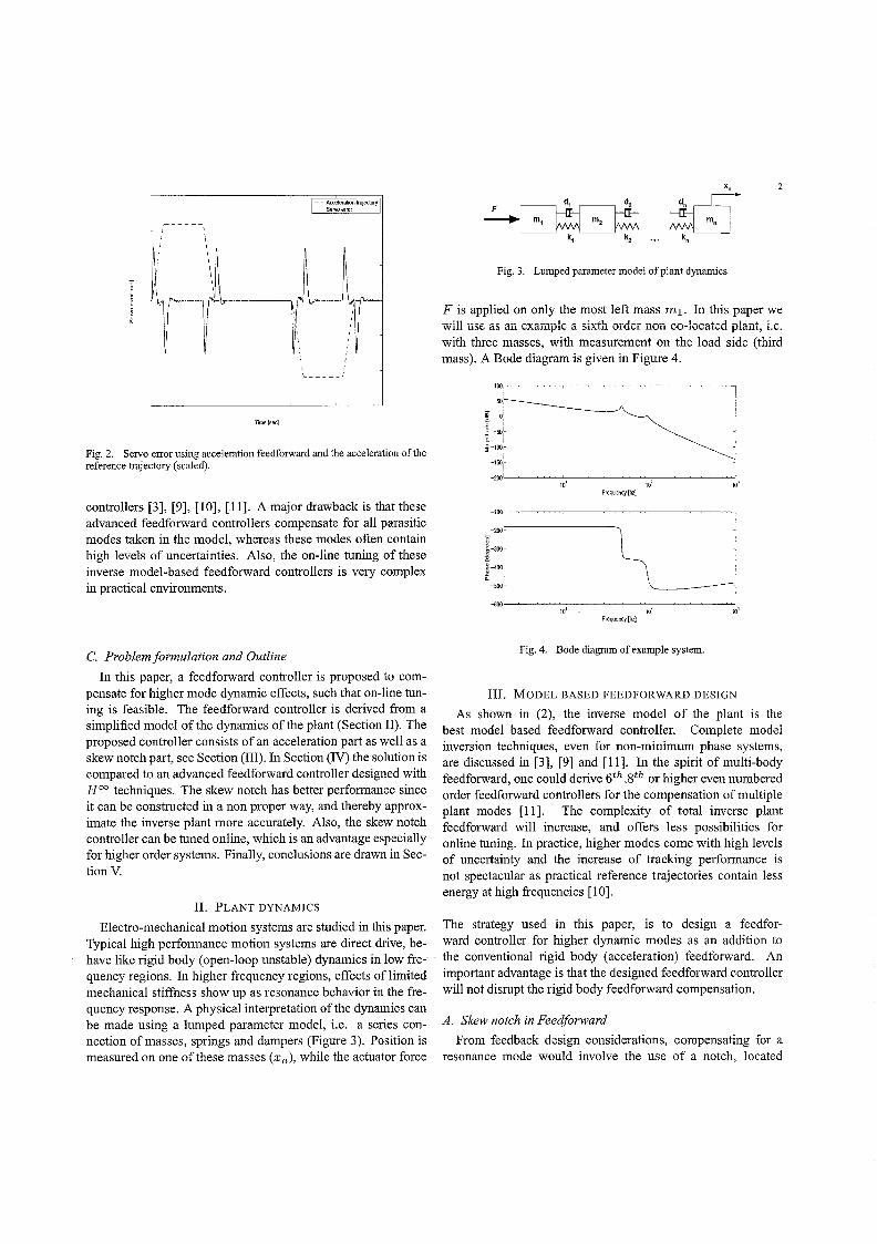
In many industrial motion controllers, acceleration feedforward is used. This feedforward action compensates for the low frequent, rigid body behavior of the plant dynamics and therefore compensates the mass line in the frequency response of the plant. In industrial practice acceleration feedforward is always tuned on-line with a simple gain, correcting for uncertainties in the overall loop gain (mass, amplifier gain, sensor gains etc). With a well tuned feedback [8] and acceleration feedforward controller, servo errors during a motion may not be zero due to parasitic dynamics (see Figure 2). These servo errors increase with more severe motions (e.g. shorter motion profiles or steeper trajectories, i.e. higher jerks (derivative of acceleration) and accelerations) and peak during the jerk phases of the reference trajectory. The servo errors are highly reproducible and limit performance in both tracking and point-to-point motion systems.
B. Advancedfeedforward
The oscillatory effect in these servo errors can be reduced by using impulse input shapers [2], [7]. Impulse input shapers can be considered as special cases of notch filters, that are uniquely formulated to achieve fast motions with minimum residual vibrations [4],[5]. However, analysis of the inverse dynamics shows that a pure (albeit damped) notch does not match the inverse dynamics exactly. In literature, plant inversion techniques are discussed to make higher mode feedforward
I I
I
I -Acce!erationtrajectory -Servoerror
:, ~ ;I-b~~-----' u~ \
TIme [sec]
I
I I I I I
\ I 1.... _____ ,
Fig. 2. Servo error using acceleration feedforward and the acceleration of the reference trajectory (scaled).
controllers [3], [9], [10], [11]. A major drawback is that these advanced feedforward controllers compensate for all parasitic modes taken in the model, whereas these modes often contain high levels of uncertainties. Also, the on-line tuning of these inverse model-based feedforward controllers is very complex in practical environments.
C. Problem formulation and Outline
In this paper, a feedforward controller is proposed to compensate for higher mode dynamic effects, such that on-line tuning is feasible. The feedforward controller is derived from a simplified model of the dynamics of the plant (Section II). The proposed controller consists of an acceleration part as well as a skew notch part, see Section (III). In Section (IV) the solution is compared to an advanced feedforward controller designed with H= techniques. The skew notch has better performance since it can be constructed in a non proper way, and thereby approximate the inverse plant more accurately. Also, the skew notch controller can be tuned online, which is an advantage especially for higher order systems. Finally, conclusions are drawn in Section V.
II. PLANT DYNAMICS
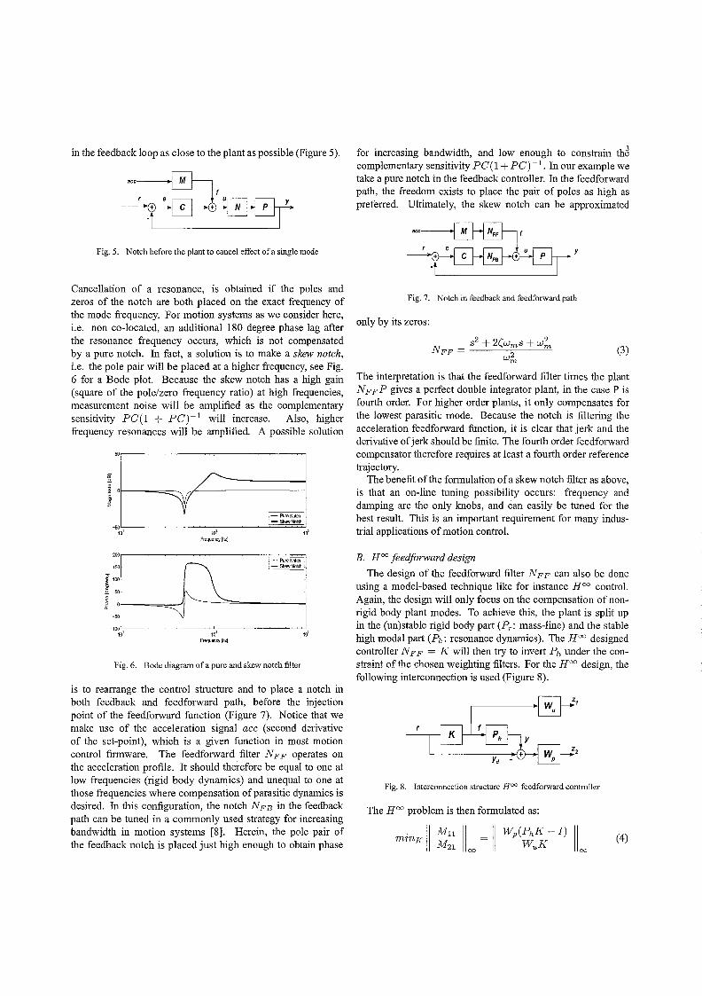
Electro-mechanical motion systems are studied in this paper. Typical high performance motion systems are direct drive, behave like rigid body (open-loop unstable) dynamics in low frequency regions. In higher frequency regions, effects of limited mechanical stiffness show up as resonance behavior in the frequency response. A physical interpretation of the dynamics can be made using a lumped parameter model, i.e. a series connection of masses, springs and dampers (Figure 3). Position is measured on one ofthese masses (xn ), while the actuator force
Fig. 3. Lumped parameter model of plant dynamics
F is applied on only the most left mass mI. In this paper we will use as an example a sixth order non co-located plant, i.e. with three masses, with measurement on the load side (third mass). A Bode diagram is given in Figure 4.
50
~ 0
~ -50
~ ~-100
-150
-100
-200
:-~-300 "-~ -400
~ -500
-600
10' 10' Frequency [hz1
10' 10' Frequency [hz]
Fig. 4. Bode diagram of example system.
III. MODEL BASED FEED FORWARD DESIGN
As shown in (2), the inverse model of the plant is the best model based feedforward controller. Complete model inversion techniques, even for non-minimum phase systems, are discussed in [3], [9] and [11]. In the spirit of multi-body feedforward, one could derive 6th ,8th or higher even numbered order feedforward controllers for the compensation of multiple plant modes [11]. The complexity of total inverse plant feedforward will increase, and offers less possibilities for online tuning. In practice, higher modes come with high levels of uncertainty and the increase of tracking performance is not spectacular as practical reference trajectories contain less energy at high frequencies [10].
The strategy used in this paper, is to design a feedforward controller for higher dynamic modes as an addition to the conventional rigid body (acceleration) feedforward. An important advantage is that the designed feedforward controller will not disrupt the rigid body feedforward compensation.
A. Skew notch in Feedforward
From feedback design considerations, compensating for a resonance mode would involve the use of a notch, located
in the feedback loop as close to the plant as possible (Figure 5).
Fig. 5. Notch before the plant to cancel effect of a single mode
Cancellation of a resonance, is obtained if the poles and zeros of the notch are both placed on the exact frequency of the mode frequency. For motion systems as we consider here, i.e. non co-located, an additional 180 degree phase lag after the resonance frequency occurs, which is not compensated by a pure notch. In fact, a solution is to make a skew notch, i.e. the pole pair will be placed at a higher frequency, see Fig. 6 for a Bode plot. Because the skew notch has a high gain (square of the pole/zero frequency ratio) at high frequencies, measurement noise will be amplified as the complementary sensitivity PC(1 + PC)-l will increase. Also, higher frequency resonances will be amplified. A possible solution
~ o~---===~~ ~~----------------~ ~ ~
-PureNotch
_50L-__ ~~ __ ~~~~ __ ~ __ ~.'=-==Sk",,'W:2NO,:,,:t'hz:J to'
200
15 0
0
0
-5 0
-100 10'
~
to' Frequency[hz]
[\ 10'
Frequency [hz]
I.-PllreNotdt -SkewNolch
Fig. 6. Bode diagram of a pure and skew notch filter
10'
10'
is to rearrange the control structure and to place a notch in both feedback and feedforward path, before the injection point of the feedforward function (Figure 7). Notice that we make use of the acceleration sigual ace (second derivative of the set-point), which is a given function in most motion control firmware. The feedforward filter N F F operates on the acceleration profile. It should therefore be equal to one at low frequencies (rigid body dynamics) and unequal to one at those frequencies where compensation of parasitic dynamics is desired. In this configuration, the notch N F B in the feedback path can be tuned in a commonly used strategy for increasing bandwidth in motion systems [8]. Herein, the pole pair of the feedback notch is placed just high enough to obtain phase
for increasing bandwidth, and low enough to constrain th~ complementary sensitivity PC (1 + PC) -1. In our example we take a pure notch in the feedback controller. In the feedforward path, the freedom exists to place the pair of poles as high as preferred. Ultimately, the skew notch can be approximated
aCC~f
.~ y
Fig. 7. Notch in feedback and feedforward path
only by its zeros:
(3)
The interpretation is that the feedforward filter times the plant N F F P gives a perfect double integrator plant, in the case P is fourth order. For higher order plants, it only compensates for the lowest parasitic mode. Because the notch is filtering the acceleration feedforward function, it is clear that jerk and the derivative of jerk should be finite. The fourth order feedforward compensator therefore requires at least a fourth order reference traj ectory.
The benefit of the formulation ofa skew notch filter as above, is that an on-line tuning possibility occurs: frequency and damping are the only knobs, and can easily be tuned for the best result. This is an important requirement for many industrial applications of motion control.
B. HOC feedforward design
The design of the feedforward filter N F F can also be done using a model-based technique like for instance HOC control. Again, the design will only focus on the compensation of nonrigid body plant modes. To achieve this, the plant is split up in the (un)stable rigid body part (Pr : mass-line) and the stable high modal part (Ph: resonance dynamics). The HOC designed controller N F F = K will then try to invert Ph under the constraint of the chosen weighting filters. For the HOC design, the following interconnection is used (Figure 8).
Fig. 8. Interconnection structure H= feedforward controller
The HOC problem is then formulated as:
(4)
The controller K, in this interconnection, is internally stable, which means that in case of non-minimum phase dynamics in Ph, no unstable zeros are cancelled. The perfonnance weight Wp is chosen as a 2nd order low-pass filter. The high frequency amplification is then reduced and properness is guaranteed. The input weighting filter Wu is chosen as a small constant, small enough not to affect the Mll problem, but still nOD-zero in order to fulfill Ricatti solver conditions. In practical situations, Wu can be designed to avoid actuator saturation.
The Hoo designed feedforward controller shows a good approximation of the inverse plant up to the chosen cut-off frequency of Wp. The effects of this cut-off frequency, are similar to the frequency of the pole pair in the skew notch configuration. An Hoo controller for a fourth order plant, will therefore be a worse approximation to the inverted plant than the proposed skew notch controller (according to 3). Also notice that it is possible that DC-gain of the calculated filter is not exactly equal to one, in our case is appeared to be 0.9998. Even such a small deviation has a significant effect on the rigid body compensation, i.e. the acceleration feedforward. Hence, the DC-gain is forced to equal unity with a negligible loss of high frequent optimality, by adjusting the gain of the filter. For multi mode systems (n > 2 Figure 3), the same HOO design setup can be used. Again, the inverse of the plant will be approximated up to the specified cut off frequency.
IV. SIMULATIONS AND ANALYSIS
Feedforward design for the sixth order plant example is illustrated. The system shows two resonance peaks in the frequency response (48 and 100 Hz respectively), see again Fig. 4. For this system a feedback controller is used, consisting of a lead/lag filter as well as a pure notch to cancel the first resonance. The cross-over frequency (where the open-loop gain PC equals 0 dB) is at 12 Hz with appropriate robustness margins [8]. Conventional acceleration feedforward is used to compensate for the rigid body behavior. The servo errors with this setup are shown in Figure 11. The skew notch (3), and the H OO feedforward controller will be designed on a model containing only the first plant mode.
The frequency responses of the skew notch and H OO controller are very similar. However, the skew notch (3) has the advantage of a non-proper construction possibility, i.e. to translate it in tenns of a feedforward signal. The H OO controller has to rely on the filtering of the acceleration signal and only approximates the first mode plant inverse up to the frequency specified in the design weight filters (Wp). The frequency response ofthe feedforward filters, is shown in Figure 9. It is visible that the skew notch and the H oo controller approximate the plant inverse up to a certain frequency.
4
100
Frequency(H;o)
Fig. 9. Magnitude frequency responses of the feedforward controllers compared to the inverse plant modes.
A. Tracking error function
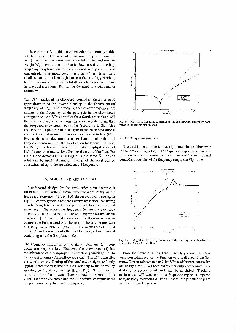
The tracking error function eq. (1) relates the tracking error to the reference trajectory. The frequency response function of this transfer function shows the performance of the feedforward controllers over the whole frequency range, see Figure 10.
Sode Magoitude Oiagram
-100
Frequency(Hz)
Fig. 10. Magnitude frequency responses of the tracking error function for several feedforward controllers.
From the figure it is clear that all newly proposed feedforward controllers reduce the function very well around the first mode. The stretched notch and the Hoo feedforward controller, are nearly similar. As both controllers only compensate the -4 slope, the second plant mode will be amplified. Tracking perfonnance will worsen in this frequency region, compared to rigid body feedforward. For all cases, the product of plant and feedforward is proper.
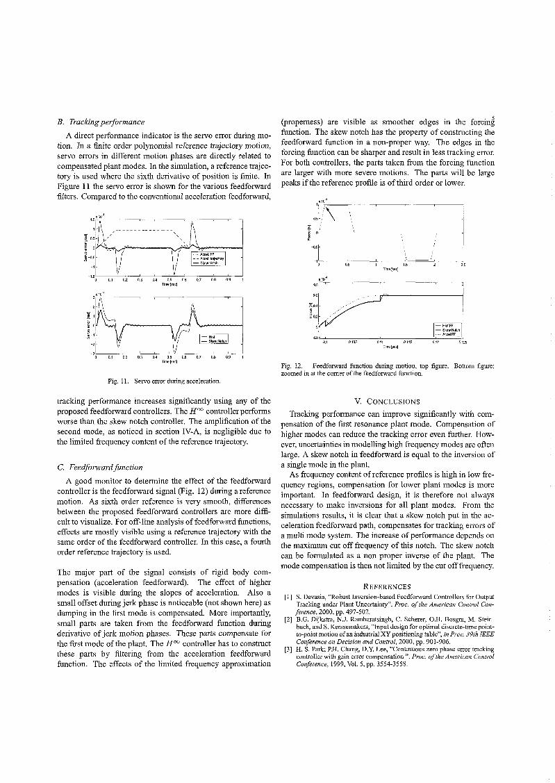
B. Tracking performance
A direct performance indicator is the servo error during motion. In a finite order polynomial reference trajectory motion, servo errors in different motion phases are directly related to compensated plant modes. In the simulation, a reference trajectory is used where the sixth derivative of position is finite. In Figure 11 the servo error is shown for the various feedforward filters. Compared to the conventional acceleration feedforward,
., ~'OL--~0.-'--0~.2--~O.3---0~.4--~~~~~~0~.8--~0.9~~
Time [sec]
Fig. 11. Servo error during acceleration.
tracking performance increases significantly using any of the proposed feedforward controllers. The H oo controller performs worse than the skew notch controller. The amplification of the second mode, as noticed in section IV-A, is negligible due to the limited frequency content of the reference trajectory.
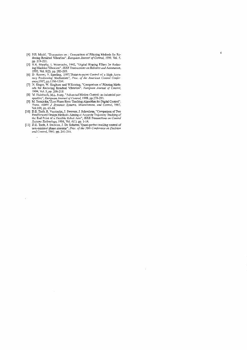
C. Feedforward function
A good monitor to determine the effect of the feedforward controller is the feedforward signal (Fig. 12) during a reference motion. As sixth order reference is very smooth, differences between the proposed feedforward controllers are more difficult to visualize. For off-line analysis offeedforward functions, effects are mostly visible using a reference trajectory with the same order of the feedforward controller. In this case, a fourth order reference trajectory is used.
The major part of the signal consists of rigid body compensation (acceleration feedforward). The effect of higher modes is visible during the slopes of acceleration. Also a small offset during jerk phase is noticeable (not shown here) as damping in the first mode is compensated. More importantly, small parts are taken from the feedforward function during derivative of jerk motion phases. These parts compensate for the first mode of the plant. The H oo controller has to construct these parts by filtering from the acceleration feedforward function. The effects of the limited frequency approximation
(properness) are visible as smoother edges in the forcing function. The skew notch has the property of constructing the feedforward function in a non-proper way. The edges in the forcing function can be sharper and result in less tracking error. For both controllers, the parts taken from the forcing function are larger with more severe motions. The parts will be large peaks if the reference profile is of third order or lower.
! 0
~ -0.5
"0 L -------:0.':-' ------:------~1.,;-==~-:;------:;2.' Timelsec)
>:10-1
9.8
9.6
~9.4 ~ ~9.2
-HinfFF -SkewNotch
8.8Lc ____ ----c=-____ :c'::-____ -:7;::--__ ~·:;'··=A£=re=IF=F =;!! 0.105 0.11 0.115 0.12 0.125 0.1
Time [sec]
Fig. 12. Feedforward function during motion, top figure. Bottom figure; zoomed in at the corner of the feedforward function.
V. CONCLUSIONS
Tracking performance can improve significantly with compensation of the first resonance plant mode. Compensation of higher modes can reduce the tracking error even further. However, uncertainties in modelling high frequency modes are often large. A skew notch in feedforward is equal to the inversion of a single mode in the plant.
As frequency content of reference profiles is high in low frequency regions, compensation for lower plant modes is more important. In feedforward design, it is therefore not always necessary to make inversions for all plant modes. From the simulations results, it is clear that a skew notch put in the acceleration feedforward path, compensates for tracking errors of a multi mode system. The increase of performance depends on the maximum cut off frequency of this notch. The skew notch can be formulated as a non proper inverse of the plant. The mode compensation is then not limited by the cut off frequency.
REFERENCES
[1] S Devasia "Robust Inversion-based Feedforward Controllers for Output T~acking u'nder Plant Uncertainty". Proc. fif the American Control Con-ference, 2000, pp. 497-502. .
[2] E.G. Dijkstra, N.J. Rambaratsingh, C. Scherer, O.R. Bosgra, M. Stembuch, and S. Kerssemakers, "Input design for optimal discrete-time pointto-point motion ofan industrial XY positioning table", in Proc. 39th IEEE Conference on Decision and Control, 2000, pp. 901-906.
[3] H. S. Park; P.R. Chang, D.Y. Lee, "Continuous zero phase error tracking controller with gain error compensation". Proc. of the American Control Conference, 1999, Vol. 5, pp. 3554-3558.
[4] P.H. Meckl, "Discussion on: Comparison of Filtering Methods for Reducing Residual Vibration". European Journal of Control, 1999, Vol. 5, pp.219-221.
[5] B.R. Murphy, I. Watanaabe, 1992, "Digital Shaping Filters for Reducing Machine Vibration". IEEE Transactions on Robotics and Automation, 1992, Vol. 8(2), pp. 285-289.
[6] D. Roover, F. Sperling, 1997,"Point-to-point Control of a High Accuracy Positioning Mechanism", Proc. of the American Control Conference,1997, pp.1350-1354.
[7] N. Singer, W. Singhose and W.Seering, "Comparison of Filtering Methods for Reducing Residual Vibration". European Journal of Control, 1999, Vol. 5, pp. 208-218.
[8] M. Steinbuch, M.L. Norg, "Advanced Motion Control: an industrial perspective", European Journal of Control, 1998, pp.278-293.
[9] M. Tomizuka,"Zero Phase Error Tracking Algorithm for Digital Control". Trans. ASME J. Dynamic Systems, Measurement, and Control, 1987, Vo1.109, pp. 65-68.
[10] D.E. Torfs, R. Vuerinckx, J. Swevers, J. Schoukens, "Comparison of Two Feedforward Design Methods Aiming at Accurate Trajectory Tracking of the End Point of a Flexible Robot Arm", IEEE Transactions on Control Systems Technology, 1998, Vol. 6(1). pp. 1-14.
[11] D.E. Torfs, J. Swevers, J. De Schutter,"Quasi-perfect tracking control of non-minimal phase systems". Proc. of the 30th Conference on Decision and Control, 1991. pp. 241-244.
Discussion on: "Analysis of model based feedforward for motion systems"
Matthijs Boerlage Eindhoven University of Technology
Faculty of Mechanical Engineering, Control Systems Technology Group
P.O. Box 513, 5600 MB Eindhoven, The Netherlands
Email: [email protected]
Abstract- This paper discusses the skew notch feedforward controller proposed in [1]. As an addition to this, some theories are expanded and relations with other technologies are discussed. A more simple higher mode feedforward controller is derived and an online tuning result for higher mode systems is enlightened. Finally, areas of future research are proposed.
I. INTRODUCTION
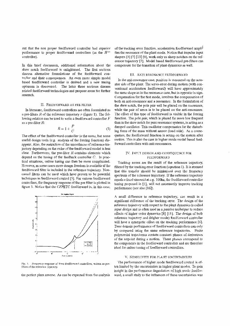
In today's motions systems, high performance requirements push the limits of control systems engineering. A commonly used architecture for motion control is given in figure 1). Feedback control C is used for robust stabilization and disturbance rejection while tracking performance is increased using feedforward control and pre-filtering (F,R). In many motion control systems, feedforward controllers are designed using rigid body models of the plant dynamics. In this discussion, the plant is
Fig. I. 3DOF control system architecture. P,C,R,F denote fue plant, feedback controller, pre-filter and feedforward respectively. The signals d,r,e,u,f,y denote fue desired trajectory, reference trajectory, servo error plant input, feedforward function and plant output.
linear time invariant (LTI) single input single output (SISO), open loop unstable due to a double low frequent integrator (direct drive mass) and contains higher frequency modes as a result of limited mechanical stiffness. The plant dynamics can be visualized using a lumped parameter multiple mode mass-springdamper model (figure 2). For stability and disturbance rejec-
Fig. 2. Lumped parameter model of plant dynamics
tion, a conventional Lead Lag feedback controller with skew
notch is used (PD+). The feedback controller is tuned using loop shaping techniques [14] leaving proper stability margins (sensitivity peak below 6dB). Rigid body (acceleration) feedforward is assumed to be tuned correctly, resulting in compensation of the massline of the plant dynamics. In this tuning, servo errors remain during motion as a result of uncompensated higher mode dynamics (figure 6, see also [1]). Tracking performance can be expressed in the frequency domain using the tracking error junction:
~ = 1 - P F = 5(1- P F) r 1+PC
(1)
Where the factor (1 - P F) is filtered with the sensitivity function 5 = (1 + PC)~l to obtain the transfer from reference trajectory (r) to servo error (e). To reduce tracking errors during motion, this transfer function must be minimized. Model based methodologies to accomplish this, are to approximate the inverse ofthe plant dynamics (P) with a feedforward controller (F). A full inverse plant model can be calculated using e.g. ZPETC or CZPETC [15] [6] [17] [16]. However, the ease of online tuning decreases with increased feedforward complexity. Furthermore, tracking performance does not improve spectacularly with compensation (inversion) of high plant modes as a result of limited energy at higher frequencies in the reference trajectories and the drop off due to higher order plant dynamics.
In [1], a methodology was proposed to compromise between the increase of feedforward complexity and the improvement of tracking performance. The result was a fourth order feedforward controller, formulated as a skew notch multiplied with the conventional acceleration feedforward. The skew notch could be implemented as a non proper filter (constructed from motion phases of the reference trajectory) or as a proper filter in series with conventional acceleration feedforward (which was the setup of the calculated HOC feedforward controller). The non proper formulation of the skew notch approximated the inverse of a single plant mode:
M S2 + 2(mwms + w~ JVFF= ------~~--~~
w~ (2)
Where Wm and (m denote the resonance frequency and damping of the plant mode respectively. Simulations pointed
out that the non proper feedforward controller had superior perfonnance to proper feedforward controllers (as the Hoo controller).
In this brief discussion, additional infonnation about the skew notch feedforward is enlightened. The first sections discuss alternative fonnulations of the feedforward controller and their consequences. An even more simple model based feedforward controller is derived and a new tuning optimum is discovered. The latter three sections discuss related feedforward technologies and propose areas for further research.
II. FEEDFORWARD AS PRE FILTER
In literature, feedforward controllers are often fonnulated as a pre-filters R of the reference trajectory r (figure 1). The following relation can be used to write a feedforward controller F as a pre-filter R:
F R=l+
C (3)
The effect of the feedforward controller is the same, but some useful design tools (e.g. analysis of the forcing function) disappear. Also, the restriction ofthe smoothness of reference trajectory depending on the order of the feedforward model is less clear. Furthennore, the pre-filter R contains elements which depend on the tuning of the feedback controller C. In practical Situations, online tuning can then be more complicated. However, in some cases more design freedom is available ifthe feedforward filter is included in the reference trajectory. Noncausal filters can be used which have proven to be powerful techniques in feedforward control [5). For various feedforward controllers, the frequency response ofthe pre filter is plotted in figure 3. Notice that the CZPETC feedforward is, in this case,
""
. ~';;--~~~;--~~~c--~~~~~~.....J 100 101 w2 to~ 1~4
Fr~ve~y([oosec)
Fig. 3. Frequency response of three feedforward controllers, written as prefilters of the reterence trajectory
the perfect plant inverse. As can be expected from the analysis
of the tracking error function, acceleration feedforward ampli~ fies the resonance of the plant mode. Notice that impulse input shapers [3] [7] [13] [9], work only as sharp notches on the reference trajectory [7]. Model based feedforward pre-filters can compensate for the transition of plant dynamics as well.
III. ANTI RESONANCE FEEDFORWARD
In the anti-resonance case, position is measured on the actLiator side of the plant. The servo error during motion (with conventional acceleration feedforward) will have approximately the same shape as in the resonance case, but is opposite in sign. Compensation for the first mode, involves the compensation of both an anti-resonance and a resonance. In the fonnulation of the skew notch, the pole pair will be placed on the resonance, while the pair of zeros is to be placed on the anti-resonance. The effect of this type of feedforward is visible in the forcing function. The pole pair, which is placed far more low frequent than in the skew notch for pure resonance systems, is acting as a damped oscillator. This oscillator compensates for the disturbing force ofthe mass without sensor (load side). As a consequence, the feedforward function is acting on the system after motion. This is also the case in higher mode model based feedforward controllers with anti-resonances.
IV. INPUT DESIGN AND CONSEQUENCE FOR
FEEDFORWARD
Tracking errors are the result of the reference trajectory, filtered by the tracking error function (equation I). It is stressed that this transfer should be minimized over the frequency spectrum of the reference trajectory. Ifthe reference trajectory equals a fixed sinusoid at e.g. 100hz, the feedforward controller tuning proposed in [1], will not necessarily improve tracking performance (see also [16]).
A small difference in reference trajectory, can result in a significant difference of the tracking error. The design of the reference trajectory with respect to the plant dynamics is called input design and is often used as a passive technique to reduce effects of higher order dynamics [8] [11]. The design of both reference trajectory and (higher mode) feedforward controller will have a synergetic effect on the tracking perfonnance [6]. Time domain perfonnance of feedforward controllers can only by compared using the same reference trajectories. Finite polynomial trajectories contain constant phases of derivatives of the setpoint during a motion. These phases correspond to the components in the feedforward controller and are therefore ideal for online tuning offeedforward controllers .
V. SENSITIVITY FOR PLANT UNCERTAINTIES
The perfonnance of higher mode feedforward control is often limited by the uncertainties in higher plant modes. To gain insight in the perfonnance degradation of high mode feedforward, a small study to the influences of these uncertainties was
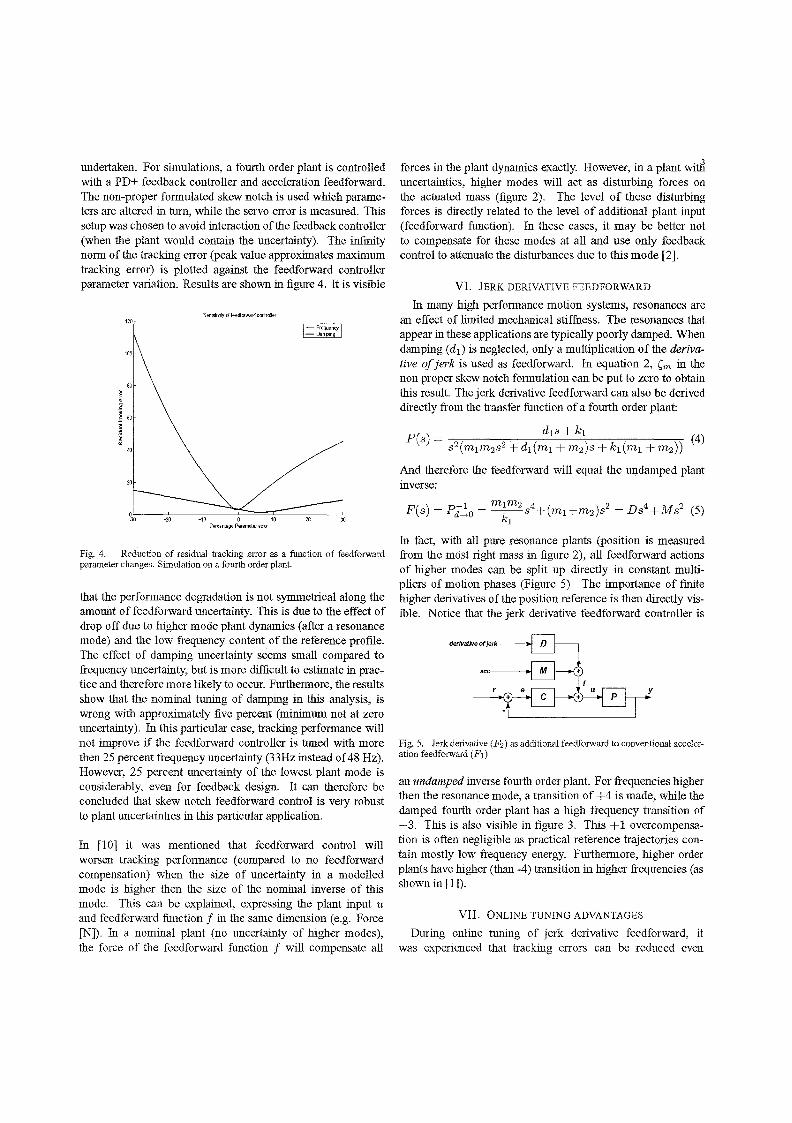
undertaken. For simulations, a fourth order plant is controlled with a PD+ feedback controller and acceleration feedforward. The non-proper formulated skew notch is used which parameters are altered in turn, while the servo error is measured. This setup was chosen to avoid interaction of the feedback controller (when the plant would contain the uncertainty). The infinity norm of the tracking error (peak value approximates maximum tracking error) is plotted against the feedforward controller parameter variation. Results are shown in figure 4. It is visible
SenslllVIfy d feedfaward cwtroller 120
40
20
~~O----~~O-----~'0--~~O~==~1O~=-~2~O--~30 PerCBntage Parameter emx
Fig. 4. Reduction of residual tracking error as a function of feedforward parameter changes. Simulation on a fourth order plant.
that the performance degradation is not symmetrical along the amount of feedforward uncertainty. This is due to the effect of drop off due to higher mode plant dynamics (after a resonance mode) and the low frequency content of the reference profile. The effect of damping uncertainty seems small compared to frequency uncertainty, but is more difficult to estimate in practice and therefore more likely to occur. Furthermore, the results show that the nominal tuning of damping in this analysis, is wrong with approximately five percent (minimum not at zero uncertainty). In this particular case, tracking performance will not improve if the feedforward controller is tuned with more then 25 percent frequency uncertainty (33Hz instead of 48 Hz). However, 25 percent uncertainty of the lowest plant mode is considerably, even for feedback design. It can therefore be concluded that skew notch feedforward control is very robust to plant uncertainties in this particular application.
In [10] it was mentioned that feedforward control will worsen tracking performance (compared to no feedforward compensation) when the size of uncertainty in a modelled mode is higher then the size of the nominal inverse of this mode. This can be explained, expressing the plant input u and feedforward function f in the same dimension (e.g. Force [N]). In a nominal plant (no uncertainty of higher modes), the force of the feedforward function f will compensate all
forces in the plant dynamics exactly. However, in a plant witli uncertainties, higher modes will act as disturbing forces on the actuated mass (figure 2). The level of these disturbing forces is directly related to the level of additional plant input (feedforward function). In these cases, it may be better not to compensate for these modes at all and use only feedback control to attenuate the disturbances due to this mode [2].
VI. JERK DERIVATIVE FEEDFORWARD
In many high performance motion systems, resonances are an effect of limited mechanical stiflhess. The resonances that appear in these applications are typically poorly damped. When damping (d1 ) is neglected, only a multiplication of the derivative of jerk is used as feedforward. In equation 2, (m in the non proper skew notch formulation can be put to zero to obtain this result. The jerk derivative feedforward can also be derived directly from the transfer function of a fourth order plant:
P(s) = dIS + kl s2(mlm2s2 + d1(ml + m2)s + kl(ml + m2» (4)
And therefore the feedforward will equal the undamped plant inverse:
( ) -1 mlm2 4 ( ) 2 4 2 P s = Pd-+O = ~s + ml+m2 s = Ds +Ms (5)
In fact, with all pure resonance plants (position is measured from the most right mass in figure 2), all feedforward actions of higher modes can be split up directly in constant multipliers of motion phases (Figure 5). The importance of finite higher derivatives ofthe position reference is then directly visible. Notice that the jerk derivative feedforward controller is
Fig. 5. Jerk derivative (Fz) as additional feedforward to conventional acceleration feedforward (PI)
an undamped inverse fourth order plant. For frequencies higher then the resonance mode, a transition of +4 is made, while the damped fourth order plant has a high frequency transition of -3. This is also visible in figure 3. This + 1 overcompensation is often negligible as practical reference trajectories contain mostly low frequency energy. Furthermore, higher order plants have higher (than -4) transition in higher frequencies (as shown in [1]).
VII. ONLINE TUNING ADVANTAGES
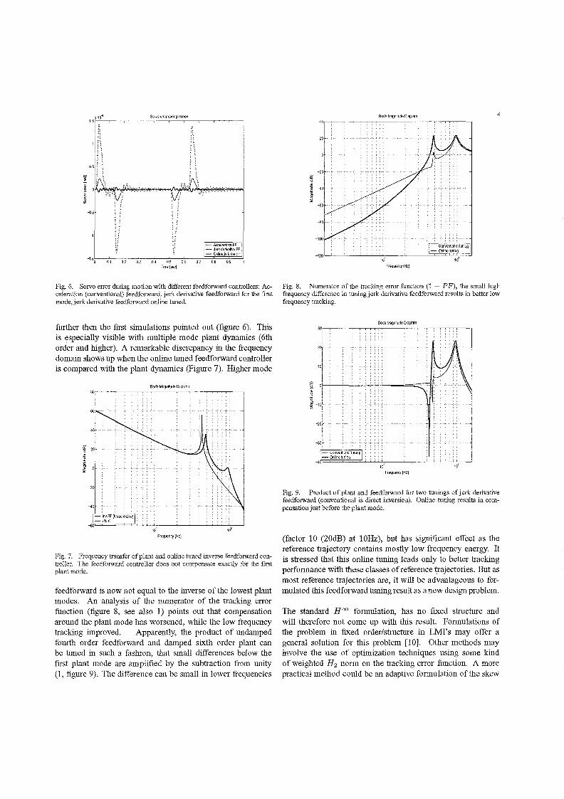
During online tuning of jerk derivative feedforward, it was experienced that tracking errors can be reduced even
1 ::
n 05
.... AcceleraiiOllFF -JerkderivaliveFF -OnlinejerkderFF
0.8 0.9
Fig. 6. Servo error during motion with different feedforward controllers: Acceleration (conventional) feedforward, jerk derivative feedforward for the first mode, jerk derivative feedforward online tuned.
further then the first simulations pointed out (figure 6). This is especially visible with multiple mode plant dynamics (6th order and higher). A r=arkable discrepancy in the frequency domain shows up when the online tuned feedforward controller is compared with the plant dynamics (Figure 7). Higher mode
i ~ 0
Bode Magmlude Dtagram
10'
Frequenq(HZ)
Fig. 7. Frequency transfer of plant and online tuned inverse feedforward controller. The feedforward controller does not compensate exactly for the first plant mode.
feedforward is now not equal to the inverse ofthe lowest plant modes. An analysis of the numerator of the tracking error function (figure 8, see also 1) points out that compensation around the plant mode has worsened, while the low frequency tracking improved. Apparently, the product of undamped fourth order feedforward and damped sixth order plant can be tuned in such a fashion, that small differences below the first plant mode are amplified by the subtraction from unity (1, figure 9). The difference can be small in lower frequencies
Bode Magn~ude Diagram 4
Frequency (Hzj
Fig. 8. Numerator of the tracking error function (1 ~ P F), the small high frequency difference in tuning jerk derivative feedforward results in better low frequency tracking.
BodeMagn~udeDagram
20
10
i ~ -10 .
-10
-30
_40F2=~='-.i....i."':"':'.L.._--,-_.i....i...i....':""';--'--'..i.i;---...J 10'
Frequency (HzJ
Fig. 9. Product of plant and feedforward for two tunings of jerk derivative feedforward (conventional is direct inversion). Online tuning results in compensation just before the plant mode.
(factor 10 (20dB) at 10Hz), but has significant effect as the reference trajectory contains mostly low frequency energy. It is stressed that this online tuning leads only to better tracking performance with these classes of reference trajectories. But as most reference trajectories are, it will be advantageous to formulated this feedforward tuning result as a new design problem.
The standard Hoo formulation, has no fixed structure and will therefore not come up with this result. Formulations of the problem in fixed order/structure in LMI's may offer a general solution for this problem [10]. Other methods may involve the use of optimization techniques using some kind of weighted H2 norm on the tracking error function. A more practical method could be an adaptive formulation of the skew
notch, where the optimal jerk derivative tuning is approximated online. The latter method has the advantage of increased robustness to varying plant dynamics. A initial guess of the optimum will be the exact inverse ofthe plant mode.
VIII. HINF FEEDFORWARD WITH CONSTRUCTION FROM
HIGHER MOTION PHASES
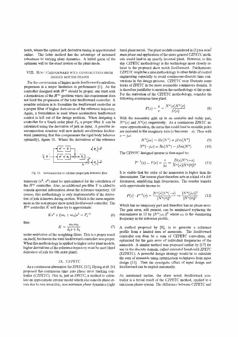
For the construction oHrigher mode feedforward controllers, properness is a major limitation in performance [1]. As the controller designed with Hoo should be proper, one must seek a formulation of the Hoo problem where this requirement does not limit the properness of the total feedforward controller. A possible solution is to formulate the feedforward controller as a proper filter of higher derivatives of the reference trajectory. Again, a formulation is used where acceleration feedforward control is left out of the design problem. When designing a controller for a fourth order plant P4, a proper filter K can be calculated using the derivative of jerk as input. A possible interconnection structure will now include acceleration feedforward (assuming that this compensates the rigid body behavior optimally), figure 10. Where the derivatives of the reference
Fig. 10. Interconnection to calculate proper jerk derivative filter
trajectory (s2, s4) must be approximated for the calculation of the Hoo controller. Also, an additional pre-filter V is added to contain spectral information about the reference trajectory. Of course, this methodology is only implementable if the derivative of jerk is known during motion. Which is the same requirement as the non-proper skew notch feedforward controller. The HOC controller K will then try to approximate:
(6)
thus (7)
under restriction ofthe weighting filters. This is a proper result on itself, but leaves the total feedforward controller non-proper. When this methodo logy is applied to higher order plant models, higher derivatives of the reference trajectory must be used (third derivative of jerk for 6th order plant).
IX. CZPETC
As a continuous alternative for ZPETC [15], Hyung et.al. [6] proposed the continuous time zero phase error tracking controller (CZPETC). This is, just as ZPETC, a method to calculate an approximate inverse model which also cancels phase errors due to non invertible, non minimum phase dynamics (right
hand plane zeros). The plant models considered in [1] are mim~ mum phase and application ofthe more general CZPETC methods would lead to an exactly inverted plant. However, to this day CZPETC methodology is the technology most closely related to the proposed skew notch feedforward. Furthermore, CZPETC might be a nice methodology in other fields of control engineering especially to avoid continuous-discrete time conversions in the design process. CZPETC may illustrate some tricks of ZPETC in the more accessible continuous domain. It is therefore justifiable to mention the methodology at this point. For the derivation of the CZPETC methodology, consider the following continuous time plant:
(8)
With the numerator split up in an unstable and stable part, NU(s) and Na(s) respectively. As a continuous ZPETC inverse approximation, the zeros that could lead to unstable poles are mirrored in the imaginary axis (s becomes -s). Thus with s = jw:
(9)
NU(-jw) = Re(NU) - jlm(NU) (10)
The CZPETC designed inverse is then equal to:
It is visible that the order of the numerator is higher then the denominator. The inverse plant therefore acts as a kind of a differentiator, amplifYing high frequencies. The residue transfer with approximate inverse is:
Which has no imaginary part and therefore has no phase error. The gain error, still present, can be minimized replacing the denominator in 12 by [NU(woW where Wo is the dominating frequency in the reference profile.
A method proposed by [6], is to generate a reference profile from a limited sum of sinusoids. The feedforward controller can then be a sum of CZPETC controllers, all optimized for the gain error of individual frequencies of the sinusoids. A similar method was proposed earlier by [17] for use in the discrete domain, called extended bandwidth ZP ETC (EZPETC). A powerful design strategy would be to calculate the sum of sinusoids using optimization techniques from input design [11]. Then the synergetic effect of input design and feedforward can be exploit maximally.
As mentioned earlier, the skew notch feedforward controller is a trivial result of the CZPETC method, applied to a minimum phase system. The difference between CZPETC and
skew notch feedforward lays in the separate design of rigid and higher mode feedforward. In skew notch formulation, the feedforward controller for high mode compensation can be tuned online without affecting the rigid body compensation. Furthermore, online tuning advantages may appear in the skew notch formulation (section VII) which are not directly visible in the CZPETC result.
X. COMPARISON TO ILC
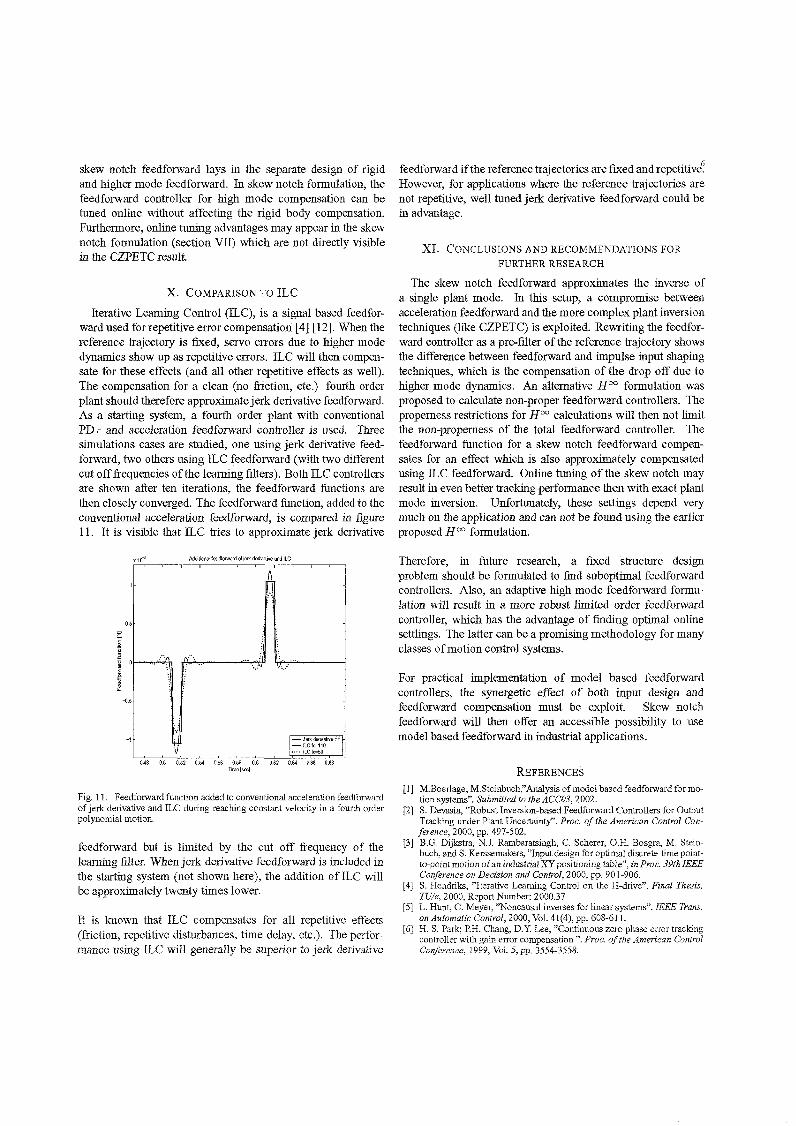
Iterative Leaming Control (ILC), is a signal based feedforward used for repetitive error compensation [4] [12]. When the reference trajectory is fixed, servo errors due to higher mode dynamics show up as repetitive errors. ILC will then compensate for these effects (and all other repetitive effects as well). The compensation for a clean (no friction, etc.) fourth order plant should therefore approximate jerk derivative feedforward. As a starting system, a fourth order plant with conventional PD+ and acceleration feedforward controller is used. Three simulations cases are studied, one using jerk derivative feedforward, two others using ILC feedforward (with two different cut offfrequencies ofthe learning filters). Both ILC controllers are shown after ten iterations, the feedforward functions are then closely converged. The feedforward function, added to the conventional acceleration feedforward, is compared in figure 11. It is visible that ILC tries to approximate jerk derivative
X 10-5
0.5
~ 2~ EO,.' '.
~
1 -D.5
-1
AdditiooalfeedforwardciJerkdenvalweandlLC
'.' v-.....
I: JerkdenvallVeFF -llCfc=110 " .. ILCfc=SO v
043 0.5 0.52 0-54 056 058 06 0.62 0.64 066 068
Fig. II. Feedforward function added to conventional acceleration feedforw-ard of jerk derivative and ILC during reaching constant velocity in a fourth order polynomial motion.
feedforward but is limited by the cut off frequency of the learning filter. When jerk derivative feedforward is included in the starting system (not shown here), the addition ofILC will be approximately twenty times lower.
It is known that ILC compensates for all repetitive effects (friction, repetitive disturbances, time delay, etc.). The performance using ILC will generally be superior to jerk derivative
feedforward ifthe reference trajectories are fixed and repetitive~ However, for applications where the reference trajectories are not repetitive, well tuned jerk derivative feedforward could be in advantage.
XI. CONCLUSIONS AND RECOMMENDATIONS FOR
FURTHER RESEARCH
The skew notch feedforward approximates the inverse of a single plant mode. In this setup, a compromise between acceleration feedforward and the more complex plant inversion techniques (like CZPETC) is exploited. Rewriting the feedforward controller as a pre-filter ofthe reference trajectory shows the difference between feedforward and impulse input shaping techniques, which is the compensation of the drop off due to higher mode dynamics. An alternative HOC formulation was proposed to calculate non-proper feedforward controllers. The properness restrictions for HOC calculations will then not limit the non-properness of the total feedforward controller. The feedforward function for a skew notch feedforward compensates for an effect which is also approximately compensated using ILC feedforward. Online tuning of the skew notch may result in even better tracking performance then with exact plant mode inversion. Unfortunately, these settings depend very much on the application and can not be found using the earlier proposed Hoo formulation.
Therefore, in future research, a fixed structure design problem should be formulated to find suboptimal feedforward controllers. Also, an adaptive high mode feedforward formulation will result in a more robust limited order feedforward controller, which has the advantage of finding optimal online settlings. The latter can be a promising methodology for many classes of motion control systems.
For practical implementation of model based feedforward controllers, the synergetic effect of both input design and feedforward compensation must be exploit. Skew notch feedforward will then offer an accessible possibility to use model based feedforward in industrial applications.
REFERENCES
[I] M.Boerlage, M.Steinbuch;' Analysis of model based feedforward for motion systems". Submitted to the ACC03, 2002.
[2] S. Devasia, "Robust Inversion-based Feedforward Controllers for Output Tracking under Plant Uncertainty". Proc. of the American Control Conference, 2000, pp. 497-502.
[3] B.G. Dijkstra, N.J. Rambaratsingh, C. Scherer, O.H. Bosgra, M. Steinbuch, and S. Kerssemakers, "Input design for optimal discrete-time pointto-point motion of an industrial XY pcsitioning table", in Pmc. 39th IEEE Conference on Decision and Control, 2000, pp. 901-906.
[4] S. Hendriks, "Iterative Learning Control on the H-drive". Final Thesis, TUle, 2000, Report Number: 2000.37
[5] L. Hunt, G. Meyer, "Noncausal inverses for linear systems". IEEE Trans, on Automatic Control, 2000, Vol. 41(4), pp. 608-611.
[6] H. S. Park; P.H. Chang, D.Y. Lee, "Continuous zero phase error tracking controller with gain error compensation ". Proc, of the American Control Conference, 1999, Vol. 5,pp. 3554-3558.
[7] P.H. Meckl, "Discussion on : Comparison of Filtering Methods for Reducing Residual Vibration". European Journal of Control, 1999, VoL 5, pp.219-221.
[8] P.H. Meckl, P.B. Arestides, M.e. Woods, "Optimized S-Curve Motion Profiles for Minimum Residual Vibration". Proc. of the American Control Conference, 1998, pp. 2627-2631.
[9] B.R. Murphy, I. Watanaabe, "Digital Shaping Filters for Reducing Machine Vibration". IEEE Transactions on Robotics and Automation, 1992, VoL 8(2), pp. 285-289.
[10] F. Paganini, A. Giusto,"Robust Synthesis of Dynamic Prefilters",Proc. of the American Control Conference, 1997, pp.1314-1318.
[II] D. Roover, F. Sperling,"Point-to-point Control of a High Accuracy Positioning Mechanism", Proc. of the American Control Conference,1997, pp.l350-1354.
[12] D. Roover;'Motion control for a wafer stage", Delft University Press, The Netherlands, 1997.
[13] N. Singer, W. Singhose and W.Seering, "Comparison of Filtering Methods for Reducing Residual Vibration". European Journal of Control, 1999, VoL 5, pp. 208-218.
[14] M. Steinbuch, M.L. Norg, "Advanced Motion Control: an industrial perspective", European Journal of Control, 1998, pp.278-293.
[15] M. Tomizuka,"Zero Phase Error Tracking Algorithm for Digital Control". Trans. ASME J Dynamic Systems, Measurement, and Control, 1987, Vol.l 09, pp. 65-68.
[16] D.E. Torfs, R. Vuerinckx, J. Swevers, J. Schoukens, "Comparison of Two Feedforward Design Methods Aiming at Accurate Trajectory Tracking of the End Point of a Flexible Robot Arm", IEEE Transactions on Control Systems Technology, 1998, VoL 6(1). pp. 1-14.
[17] D.E. Torfs, J. Swevers, J. De Schutter,"Quasi-perfect tracking control of non-minimal phase systems". Proc. of the 30th Conference on Decision and Control, 1991. pp. 241-244.