analysis of multilayer frequency selective surfaces for...
TRANSCRIPT
Analysis of Multilayer Frequency Selective Surfaces for Transmitarray
Antenna Applications
Ahmed H. Abdelrahman 1, Fan Yang
1,2, and Atef Z. Elsherbeni
1
1 Center of Applied Electromagnetic Systems Research (CAESR), Department of Electrical Engineering
University of Mississippi, University, MS 38677 USA
[email protected], [email protected], and [email protected]
2 Electronic Engineering Department
Tsinghua University, Beijing, China 100084
Abstract: Many transmitarray antennas are designed with multilayer frequency selective surface (M-FSS)
type elements. The goal of this paper is to discover the theoretical limits of M-FSS for transmitarray
designs, which is general for arbitrary element shapes. An analytical study on the transmission coefficient
of multiple-conductor layers separated by dielectric materials has been carried out, and the transmission
phase range has been determined according to the number of layers, substrate permittivity, and separation
between conductor layers. Based on the analytical study, the best performance of the transmitarray
antenna using frequency selective surfaces (FSS) is first determined by the selection of the number of
layers, substrate material, and separation between conductor layers, even before the selection of the
element shape. The effectiveness of the proposed approach has been validated through numerical
simulations of several examples of FSS such as dipole and loop geometries.
Keywords: Frequency selective surfaces (FSS), Transmitarray antenna, Transmission phase range
1. Introduction
A transmitarray antenna consists of an illuminating feed source and a flat transmitting surface
composed of one or multiple layers, as shown in Fig. 1. The feed source is usually located on an
equivalent focal point. On the transmitting surface, there is an array of printed antenna elements. The
transmission coefficients of these elements are individually designed to convert the spherical phase front
from the feed to a planar phase front. As a result, a focused radiation beam can be achieved with a high
gain. The frequency selective surfaces approach is popularly used to control the phase of each element in
the array individually by varying the element’s dimensions [1-3]. However, the required phase
compensation for practical designs cannot be achieved by only one layer of the printed antenna elements
array [1, 2]. Thus, multi-layer design in which the layers are separated by either air gap or dielectric
material is required to increase the transmission phase range of the antenna element.
This paper organizes the procedures of designing transmitarray antennas using frequency selective
surfaces. The transmission phase range limit is first determined according to the number of layers, the
substrate material, and the separation between layers. The unit cell design becomes a secondary step
where the element dimensions are to be optimized for the maximum transmission phase range possible.
29th Annual Review of Progress in Applied Computational Electromagnetics March 24-28, 2013 - Monterey, CA ©2013 ACES
135
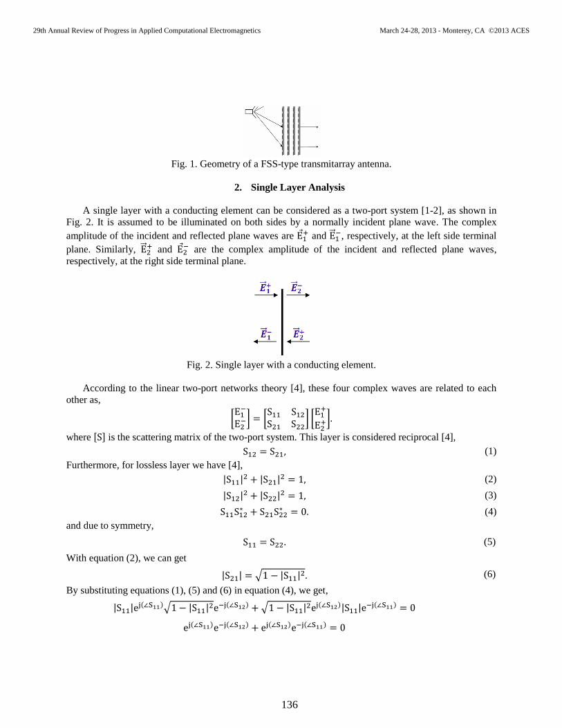
Fig. 1. Geometry of a FSS-type transmitarray antenna.
2. Single Layer Analysis
A single layer with a conducting element can be considered as a two-port system [1-2], as shown in
Fig. 2. It is assumed to be illuminated on both sides by a normally incident plane wave. The complex
amplitude of the incident and reflected plane waves are ⃗ and ⃗⃗
, respectively, at the left side terminal
plane. Similarly, ⃗⃗ and ⃗
are the complex amplitude of the incident and reflected plane waves,
respectively, at the right side terminal plane.
Fig. 2. Single layer with a conducting element.
According to the linear two-port networks theory [4], these four complex waves are related to each
other as,
[
] [
] [
]
where [ ] is the scattering matrix of the two-port system. This layer is considered reciprocal [4],
(1)
Furthermore, for lossless layer we have [4],
| | | |
(2)
| | | |
(3)
(4)
and due to symmetry,
(5)
With equation (2), we can get
| | √ | | (6)
By substituting equations (1), (5) and (6) in equation (4), we get,
| | ( )√ | |
( ) √ | | ( )| |
( )
( ) ( ) ( ) ( )
29th Annual Review of Progress in Applied Computational Electromagnetics March 24-28, 2013 - Monterey, CA ©2013 ACES
136


obtained analytically in Fig. 3. The range of varying the dipole length (from L = 0 to L = P = λ0/2 ≈ 17.5
mm) is not sufficient to cover the phase range for a complete circle as shown in Fig. 5(a), while the
double square loop element is capable of achieving the complete circle as shown in Fig. 5(b).
(a) (b)
Fig. 4. Unit cell of (a) a dipole element, and (b) a double square loop element [3].
(a) (b)
Fig. 5. Transmission coefficient of the single layer (a) dipole element, (b) double square loop element.
3. Multi Conductor Layers
Next we aim to obtain the S-matrix of multi-layer configurations as shown in Fig. 6 in order to
determine the overall transmission coefficient S12. As a starting point, one develops the S-matrix of any
two cascaded layers using the knowledge of the S-matrix of each individual layer as [1-2],
[
]
[
]
(12)
where
, and
are the S-parameters of the first layer,
, and
are the S-
parameters of the second layer,
, and
are the S-parameters of cascaded two layers.
Accordingly, the S-matrix of multiple-conductor layers separated by dielectric substrate as shown in Fig.
6, can be computed (and hence the transmission coefficient S12) by repeatedly cascading the S-matrices of
the conductor layer defined in equation (11) and the S-matrix of the dielectric substrate defined as [7],
[
]
[ ( )
( )
( )
( )
]
(13)
where,
√ √
√
29th Annual Review of Progress in Applied Computational Electromagnetics March 24-28, 2013 - Monterey, CA ©2013 ACES
138
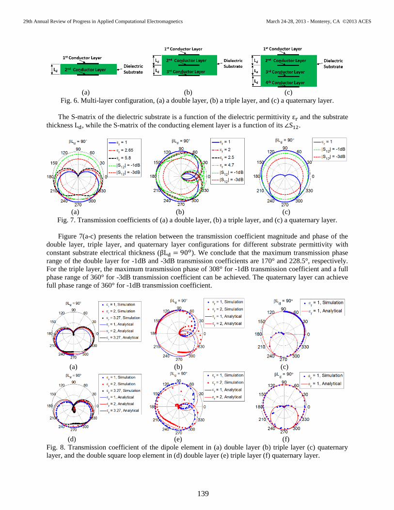
(a) (b) (c)
Fig. 6. Multi-layer configuration, (a) a double layer, (b) a triple layer, and (c) a quaternary layer.
The S-matrix of the dielectric substrate is a function of the dielectric permittivity and the substrate
thickness , while the S-matrix of the conducting element layer is a function of its .
(a) (b) (c)
Fig. 7. Transmission coefficients of (a) a double layer, (b) a triple layer, and (c) a quaternary layer.
Figure 7(a-c) presents the relation between the transmission coefficient magnitude and phase of the
double layer, triple layer, and quaternary layer configurations for different substrate permittivity with
constant substrate electrical thickness ( ). We conclude that the maximum transmission phase
range of the double layer for -1dB and -3dB transmission coefficients are 170° and 228.5°, respectively.
For the triple layer, the maximum transmission phase of 308° for -1dB transmission coefficient and a full
phase range of 360° for -3dB transmission coefficient can be achieved. The quaternary layer can achieve
full phase range of 360° for -1dB transmission coefficient.
(a) (b) (c)
(d) (e) (f)
Fig. 8. Transmission coefficient of the dipole element in (a) double layer (b) triple layer (c) quaternary
layer, and the double square loop element in (d) double layer (e) triple layer (f) quaternary layer.
29th Annual Review of Progress in Applied Computational Electromagnetics March 24-28, 2013 - Monterey, CA ©2013 ACES
139
Numerical analyses of different number of layers are carried out at 8.4 GHz with half wavelength
periodicity (P = λ0/2) using the dipole and the double square loop elements as shown in Fig. 8 using both
CST Studio Suite software [8] and Ansoft HFSS [9]. The numerical simulations show small shift from the
analytical results at some points when the permittivity increases. This is because the physical separation
between layers decreases with the increase of the substrate permittivity for constant electrical length and
leads to the increase of the high-order mode coupling between layers. Within the specified period, P, the
range of varying the dipole element length is not sufficient to cover the maximum phase range as shown
in Fig. 8(a-c), while the double square loop element is capable of achieving the maximum phase range as
shown in Fig. 8(d-f). This illustrates the importance of selecting an element like the double square loop
element rather than the dipole element in order to achieve the maximum phase range possible.
4. Conclusions
Analytical study on the transmission coefficient of multi-layer conductors separated by dielectric
material is presented in this paper. The limits of the transmission phase range for -1dB and -3dB
transmission coefficients have been derived according to the number of layers, substrate materials, and
layer separations. These analytical limits are generally applicable, independently from the selection of a
specific element shape. The proposed limits are validated through several numerical simulations. The
condition of neglecting the high-order coupling effect between the conducting layers is considered in the
analytical derivations.
Acknowledgment
This work is supported by NSF Award # ECCS-1102269
References
[1] S. Datthanasombat, Analysis and Design of High-Gain Space-Fed Passive Microstrip Array
Antennas, Doctoral Dissertation, University of Southern California, Los Angeles, CA, 2003.
[2] S. Datthanasombat, L. R. Amaro, J. A. Harrell, S. Spitz and J. Perret, “Layered lens antenna,” IEEE
Antennas and Propagation Society International Symposium, Boston, USA, pp. 777-780, July 2001.
[3] C. G. M. Ryan, M. Reza, J. Shaker, J. R. Bray, Y. M. M. Antar, and A. Ittipiboon, “A wideband
transmitarray using dual-resonant double square rings,” IEEE Transaction on Antenna and
Propagation, vol. 58, no. 5, pp. 1486-1493, May 2010.
[4] D. M. Pozar, Microwave Engineering, 3rd
Edition, John Wiley & Sons, Inc., New York, 2005.
[5] B. A. Munk, Frequency Selective Surfaces, Theory and Design, John Wiley & Sons, Inc., New York,
2000.
[6] Ansoft Designer, version 6.1.0, Ansoft Corporation, Pittsburgh, 2010.
[7] C. A. Balanis, Advanced Engineering Electromagnetics, 2nd
Edition, Wiley, New York, 2012.
[8] CST Microwave Studio, version 2012.04, Computer Simulation Technology, Darmstadt, 2012.
[9] Ansoft High Frequency Structure Simulation (HFSS), version 13.0.0, Ansoft Corporation, Pittsburgh,
2010.
29th Annual Review of Progress in Applied Computational Electromagnetics March 24-28, 2013 - Monterey, CA ©2013 ACES
140