analysis of nox reaction kinetics
TRANSCRIPT
Created in COMSOL Multiphysics 5.6
Ana l y s i s o f NOx Rea c t i o n K i n e t i c s
This model is licensed under the COMSOL Software License Agreement 5.6.All trademarks are the property of their respective owners. See www.comsol.com/trademarks.
Introduction
This example looks at the reduction of NO by ammonia. The reaction is critical to purify vehicle exhaust gases from NO. In these cases, the reaction usually takes place within the channels of a monolithic reactor situated within the exhaust system.
Central for the monolithic reactor is that NH3 is present in amounts that do not limit the NO reduction reaction. At the same time, excess NH3 at the outlet of the reactor leads to undesirable waste. The situation is complicated by the fact that ammonia can be depleted by oxidation, a reaction that is parallel to the NO reduction, and that the rates of the two competing reactions are affected by temperature as well as composition.
This tutorial aims at getting a primary understanding of the monolithic reactor. It concentrates on the investigation of the selectivity of the reactions by solving the model with the Plug Flow ideal reactor type in the Reaction Engineering interface.
Model Definition
C H E M I C A L R E A C T I O N S
NO reduction by ammonia can be summarized by the following reaction:
(1)
However, ammonia can at the same time undergo oxidation:
(2)
The heterogeneous catalytic conversion of NO to N2 is described by an Eley-Rideal mechanism. A key reaction step involves the reaction of gas-phase NO with surface-adsorbed NH3. The following rate equation (SI unit: mol/(m3·s)) has been suggested in Ref. 1 for Equation 1:
where
4NO 4N2O2+ 6H2O+4NH3+
+ 3O2 2N2 6H2O+4NH3
r1 k1cNOacNH3
1 acNH3+--------------------------=
2 | A N A L Y S I S O F N O X R E A C T I O N K I N E T I C S
and
For Equation 2, the reaction rate (SI unit: mol/(m3·s)) is given by
(3)
where
The competing chemical reactions raise the issue of optimal dosing of NH3 to handle the reduction process. Stoichiometry suggests a 1:1 ratio of NH3 to NO as a lower limit. It is likely that a stoichiometric excess of NH3 is necessary but, at the same time, we want to avoid unnecessarily high levels of NH3 in the gas stream leaving the catalytic converter.
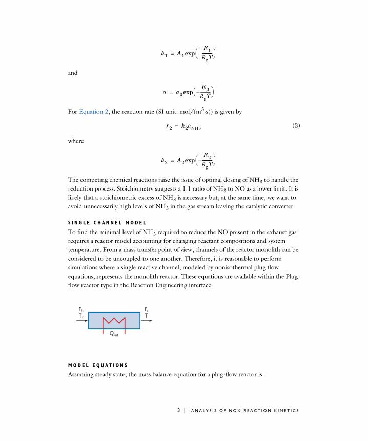
S I N G L E C H A N N E L M O D E L
To find the minimal level of NH3 required to reduce the NO present in the exhaust gas requires a reactor model accounting for changing reactant compositions and system temperature. From a mass transfer point of view, channels of the reactor monolith can be considered to be uncoupled to one another. Therefore, it is reasonable to perform simulations where a single reactive channel, modeled by nonisothermal plug flow equations, represents the monolith reactor. These equations are available within the Plug-flow reactor type in the Reaction Engineering interface.
M O D E L E Q U A T I O N S
Assuming steady state, the mass balance equation for a plug-flow reactor is:
k1 A1E1RgT----------–
exp=
a a0E0RgT----------–
exp=
r2 k2cNH3=
k2 A2E2RgT----------–
exp=
3 | A N A L Y S I S O F N O X R E A C T I O N K I N E T I C S
(4)
where Fi is the species molar flow rate (SI unit: mol/s), V represents the reactor volume (SI unit: m3), and Ri is the species net reaction rate (SI unit: mol/(m3·s)). The molar flow rate is related to the species concentrations, ci (SI unit: mol/m3), through the volumetric flow rate, v (SI unit: m3/s):
(5)
where the volumetric flow rate is given by the average flow velocity, u (SI unit: m/s), multiplied by the reactor cross-section A (SI unit: m2):
(6)
The energy balance for the ideal reacting gas is:
(7)
where Cp,i is the species molar heat capacity (SI unit: J/(mol·K)), and Qext is the heat added to the system per unit volume (SI unit: J/(m3·s)). Q denotes the heat due to chemical reaction (SI unit: J/(m3·s))
where Hj is the heat of reaction (SI unit: J/mol) for reaction j, and rj the reaction rate (SI unit: mol/(m3·s)).
The model is first solved with Equation 4, Equation 5, and Equation 6 for several different ratios of reactant concentrations (NH3:NO) and with a temperature ramp along the reactor. The molar flow rates of NH3 and NO are kept constant throughout the reactor to investigate the temperature impact alone. Thereafter, Equation 7 is included; that is, nonisothermal conditions due to heat of reaction are studied.
Results and Discussion
R E A C T I O N K I N E T I C S A N A L Y S I S
Analyzing the kinetics can help narrow down a proper NH3:NO ratio. A first study looks at the reaction rates of the reduction and oxidation reactions, for fixed molar flow rates of
Fd iVd--------- Ri=
Fi vci=
v uA=
FiCp i,dTdV--------
i Qext Q+=
Q Hjrj
j–=
4 | A N A L Y S I S O F N O X R E A C T I O N K I N E T I C S

NH3 and NO, as function of temperature and relative amounts of reactants. Figure 1 shows the reaction rates for the reduction reaction (reaction 1 above). The curves represent a set of NH3:NO ratios (X0) ranging from 1 to 2. The concentration of NO in the exhaust gas entering the catalytic converter is known to be 0.0411 mol/m3.
Figure 1: Reaction rates of the NO reduction reaction (r1) as a function of temperature. The NH3:NO ratio ranges from 1 to 2 and the molar flow rates of NH3 and NO are kept constant throughout the reactor.
The rate of NO reduction goes through a maximum and falls off at higher temperatures. The maximum shifts toward higher temperatures as the ratio NH3:NO increases. This behavior is explained by the desorption rate of NH3 from the catalyst surface becoming faster than the reaction of adsorbed NH3 with gas-phase NO.
According to Equation 3, the oxidation rate increases with increased temperature and NH3 concentration. This is seen in Figure 2, plotting the selectivity parameter S as a function of reactant ratio and temperature. S is defined as the ratio of reaction rates:
.Sr1r2-----=
5 | A N A L Y S I S O F N O X R E A C T I O N K I N E T I C S
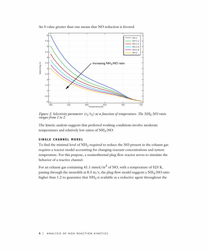
An S-value greater than one means that NO reduction is favored.
Figure 2: Selectivity parameter (r1/r2) as a function of temperature. The NH3:NO ratio ranges from 1 to 2.
The kinetic analysis suggests that preferred working conditions involve moderate temperatures and relatively low ratios of NH3:NO.
S I N G L E C H A N N E L M O D E L
To find the minimal level of NH3 required to reduce the NO present in the exhaust gas requires a reactor model accounting for changing reactant concentrations and system temperature. For this purpose, a nonisothermal plug-flow reactor serves to simulate the behavior of a reactive channel.
For an exhaust gas containing 41.1 mmol/m3 of NO, with a temperature of 523 K, passing through the monolith at 0.3 m/s, the plug-flow model suggests a NH3:NO ratio higher than 1.2 to guarantee that NH3 is available as a reductive agent throughout the
Increasing NH3:NO ratio
6 | A N A L Y S I S O F N O X R E A C T I O N K I N E T I C S
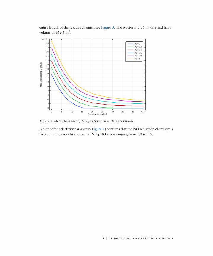
entire length of the reactive channel, see Figure 3. The reactor is 0.36 m long and has a volume of 45e-5 m3.
Figure 3: Molar flow rate of NH3 as function of channel volume.
A plot of the selectivity parameter (Figure 4) confirms that the NO reduction chemistry is favored in the monolith reactor at NH3:NO ratios ranging from 1.3 to 1.5.
7 | A N A L Y S I S O F N O X R E A C T I O N K I N E T I C S
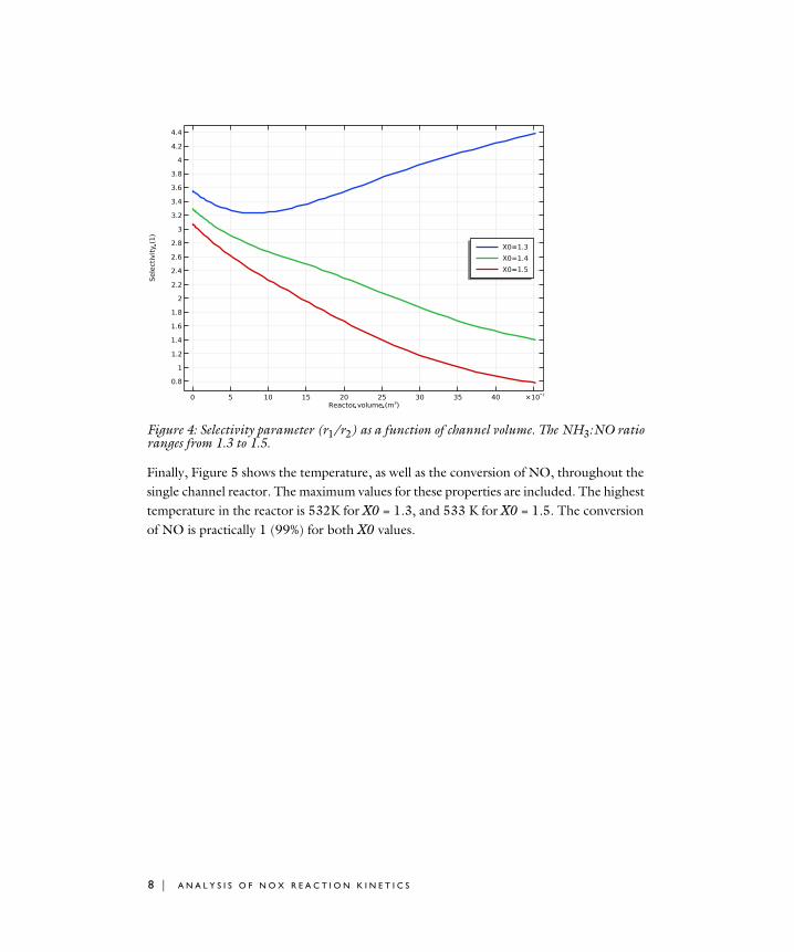
Figure 4: Selectivity parameter (r1/r2) as a function of channel volume. The NH3:NO ratio ranges from 1.3 to 1.5.
Finally, Figure 5 shows the temperature, as well as the conversion of NO, throughout the single channel reactor. The maximum values for these properties are included. The highest temperature in the reactor is 532K for X0 = 1.3, and 533 K for X0 = 1.5. The conversion of NO is practically 1 (99%) for both X0 values.
8 | A N A L Y S I S O F N O X R E A C T I O N K I N E T I C S
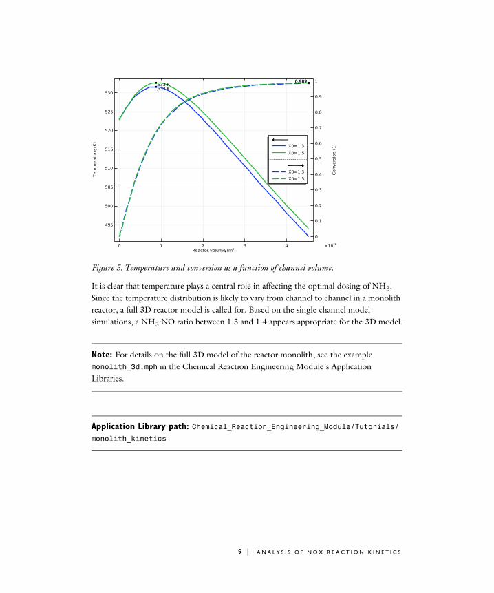
Figure 5: Temperature and conversion as a function of channel volume.
It is clear that temperature plays a central role in affecting the optimal dosing of NH3. Since the temperature distribution is likely to vary from channel to channel in a monolith reactor, a full 3D reactor model is called for. Based on the single channel model simulations, a NH3:NO ratio between 1.3 and 1.4 appears appropriate for the 3D model.
Note: For details on the full 3D model of the reactor monolith, see the example monolith_3d.mph in the Chemical Reaction Engineering Module’s Application Libraries.
Application Library path: Chemical_Reaction_Engineering_Module/Tutorials/monolith_kinetics
9 | A N A L Y S I S O F N O X R E A C T I O N K I N E T I C S
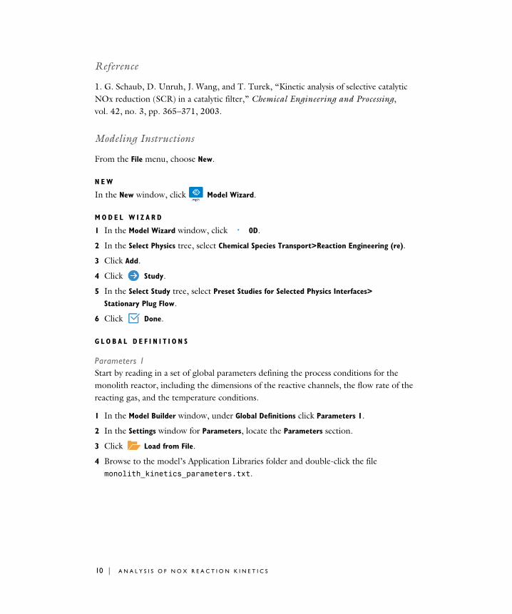
Reference
1. G. Schaub, D. Unruh, J. Wang, and T. Turek, “Kinetic analysis of selective catalytic NOx reduction (SCR) in a catalytic filter,” Chemical Engineering and Processing, vol. 42, no. 3, pp. 365–371, 2003.
Modeling Instructions
From the File menu, choose New.
N E W
In the New window, click Model Wizard.
M O D E L W I Z A R D
1 In the Model Wizard window, click 0D.
2 In the Select Physics tree, select Chemical Species Transport>Reaction Engineering (re).
3 Click Add.
4 Click Study.
5 In the Select Study tree, select Preset Studies for Selected Physics Interfaces>
Stationary Plug Flow.
6 Click Done.
G L O B A L D E F I N I T I O N S
Parameters 1Start by reading in a set of global parameters defining the process conditions for the monolith reactor, including the dimensions of the reactive channels, the flow rate of the reacting gas, and the temperature conditions.
1 In the Model Builder window, under Global Definitions click Parameters 1.
2 In the Settings window for Parameters, locate the Parameters section.
3 Click Load from File.
4 Browse to the model’s Application Libraries folder and double-click the file monolith_kinetics_parameters.txt.
10 | A N A L Y S I S O F N O X R E A C T I O N K I N E T I C S
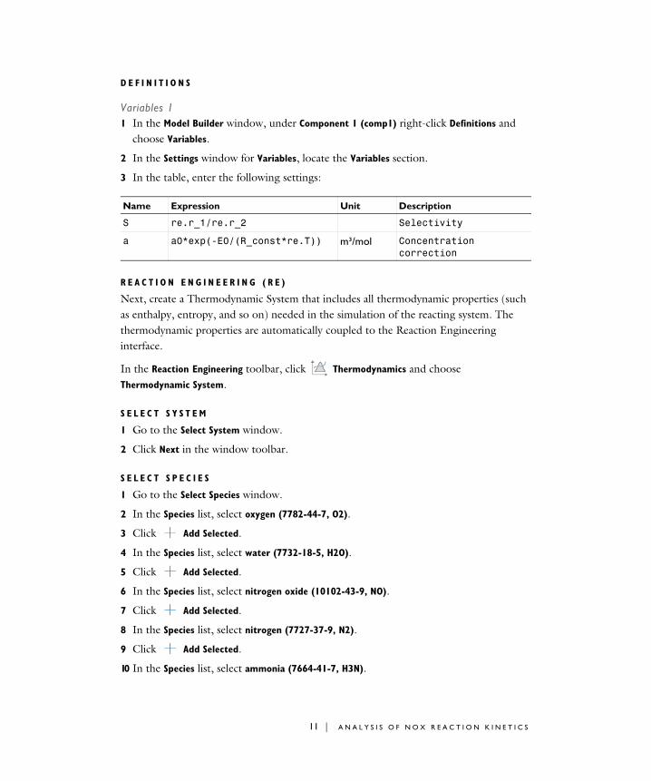
D E F I N I T I O N S
Variables 11 In the Model Builder window, under Component 1 (comp1) right-click Definitions and
choose Variables.
2 In the Settings window for Variables, locate the Variables section.
3 In the table, enter the following settings:
R E A C T I O N E N G I N E E R I N G ( R E )
Next, create a Thermodynamic System that includes all thermodynamic properties (such as enthalpy, entropy, and so on) needed in the simulation of the reacting system. The thermodynamic properties are automatically coupled to the Reaction Engineering interface.
In the Reaction Engineering toolbar, click Thermodynamics and choose Thermodynamic System.
S E L E C T S Y S T E M
1 Go to the Select System window.
2 Click Next in the window toolbar.
S E L E C T S P E C I E S
1 Go to the Select Species window.
2 In the Species list, select oxygen (7782-44-7, O2).
3 Click Add Selected.
4 In the Species list, select water (7732-18-5, H2O).
5 Click Add Selected.
6 In the Species list, select nitrogen oxide (10102-43-9, NO).
7 Click Add Selected.
8 In the Species list, select nitrogen (7727-37-9, N2).
9 Click Add Selected.
10 In the Species list, select ammonia (7664-41-7, H3N).
Name Expression Unit Description
S re.r_1/re.r_2 Selectivity
a a0*exp(-E0/(R_const*re.T)) m³/mol Concentration correction
11 | A N A L Y S I S O F N O X R E A C T I O N K I N E T I C S
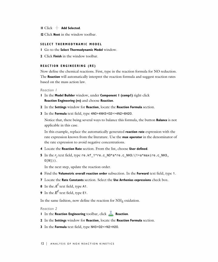
11 Click Add Selected.
12 Click Next in the window toolbar.
S E L E C T T H E R M O D Y N A M I C M O D E L
1 Go to the Select Thermodynamic Model window.
2 Click Finish in the window toolbar.
R E A C T I O N E N G I N E E R I N G ( R E )
Now define the chemical reactions. First, type in the reaction formula for NO reduction. The Reaction will automatically interpret the reaction formula and suggest reaction rates based on the mass action law.
Reaction 11 In the Model Builder window, under Component 1 (comp1) right-click
Reaction Engineering (re) and choose Reaction.
2 In the Settings window for Reaction, locate the Reaction Formula section.
3 In the Formula text field, type 4NO+4NH3+O2=>4N2+6H2O.
Notice that, there being several ways to balance this formula, the button Balance is not applicable in this case.
In this example, replace the automatically generated reaction rate expression with the rate expression known from the literature. Use the max operator in the denominator of the rate expression to avoid negative concentrations.
4 Locate the Reaction Rate section. From the list, choose User defined.
5 In the rj text field, type re.kf_1*re.c_NO*a*re.c_NH3/(1+a*max(re.c_NH3,0[M])).
In the next step, update the reaction order.
6 Find the Volumetric overall reaction order subsection. In the Forward text field, type 1.
7 Locate the Rate Constants section. Select the Use Arrhenius expressions check box.
8 In the Af text field, type A1.
9 In the Ef text field, type E1.
In the same fashion, now define the reaction for NH3 oxidation.
Reaction 21 In the Reaction Engineering toolbar, click Reaction.
2 In the Settings window for Reaction, locate the Reaction Formula section.
3 In the Formula text field, type NH3+O2=>N2+H2O.
12 | A N A L Y S I S O F N O X R E A C T I O N K I N E T I C S
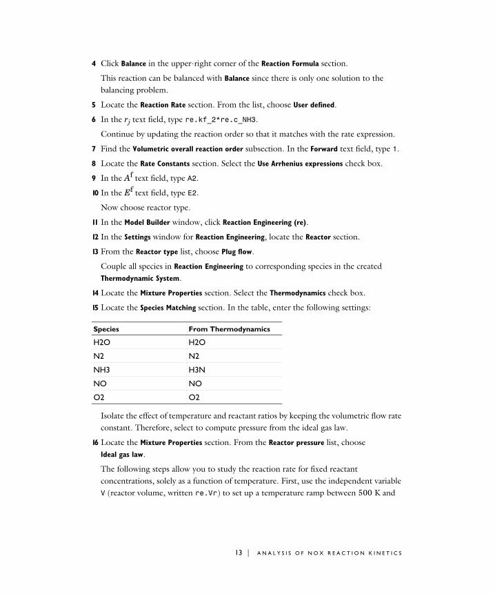
4 Click Balance in the upper-right corner of the Reaction Formula section.
This reaction can be balanced with Balance since there is only one solution to the balancing problem.
5 Locate the Reaction Rate section. From the list, choose User defined.
6 In the rj text field, type re.kf_2*re.c_NH3.
Continue by updating the reaction order so that it matches with the rate expression.
7 Find the Volumetric overall reaction order subsection. In the Forward text field, type 1.
8 Locate the Rate Constants section. Select the Use Arrhenius expressions check box.
9 In the Af text field, type A2.
10 In the Ef text field, type E2.
Now choose reactor type.
11 In the Model Builder window, click Reaction Engineering (re).
12 In the Settings window for Reaction Engineering, locate the Reactor section.
13 From the Reactor type list, choose Plug flow.
Couple all species in Reaction Engineering to corresponding species in the created Thermodynamic System.
14 Locate the Mixture Properties section. Select the Thermodynamics check box.
15 Locate the Species Matching section. In the table, enter the following settings:
Isolate the effect of temperature and reactant ratios by keeping the volumetric flow rate constant. Therefore, select to compute pressure from the ideal gas law.
16 Locate the Mixture Properties section. From the Reactor pressure list, choose Ideal gas law.
The following steps allow you to study the reaction rate for fixed reactant concentrations, solely as a function of temperature. First, use the independent variable V (reactor volume, written re.Vr) to set up a temperature ramp between 500 K and
Species From Thermodynamics
H2O H2O
N2 N2
NH3 H3N
NO NO
O2 O2
13 | A N A L Y S I S O F N O X R E A C T I O N K I N E T I C S
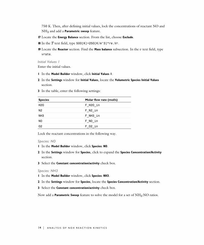
750 K. Then, after defining initial values, lock the concentrations of reactant NO and NH3 and add a Parametric sweep feature.
17 Locate the Energy Balance section. From the list, choose Exclude.
18 In the T text field, type 500[K]+250[K/m^3]*re.Vr.
19 Locate the Reactor section. Find the Mass balance subsection. In the v text field, type vrate.
Initial Values 1Enter the initial values.
1 In the Model Builder window, click Initial Values 1.
2 In the Settings window for Initial Values, locate the Volumetric Species Initial Values section.
3 In the table, enter the following settings:
Lock the reactant concentrations in the following way.
Species: NO1 In the Model Builder window, click Species: NO.
2 In the Settings window for Species, click to expand the Species Concentration/Activity section.
3 Select the Constant concentration/activity check box.
Species: NH31 In the Model Builder window, click Species: NH3.
2 In the Settings window for Species, locate the Species Concentration/Activity section.
3 Select the Constant concentration/activity check box.
Now add a Parametric Sweep feature to solve the model for a set of NH3:NO ratios.
Species Molar flow rate (mol/s)
H2O F_H2O_in
N2 F_N2_in
NH3 F_NH3_in
NO F_NO_in
O2 F_O2_in
14 | A N A L Y S I S O F N O X R E A C T I O N K I N E T I C S
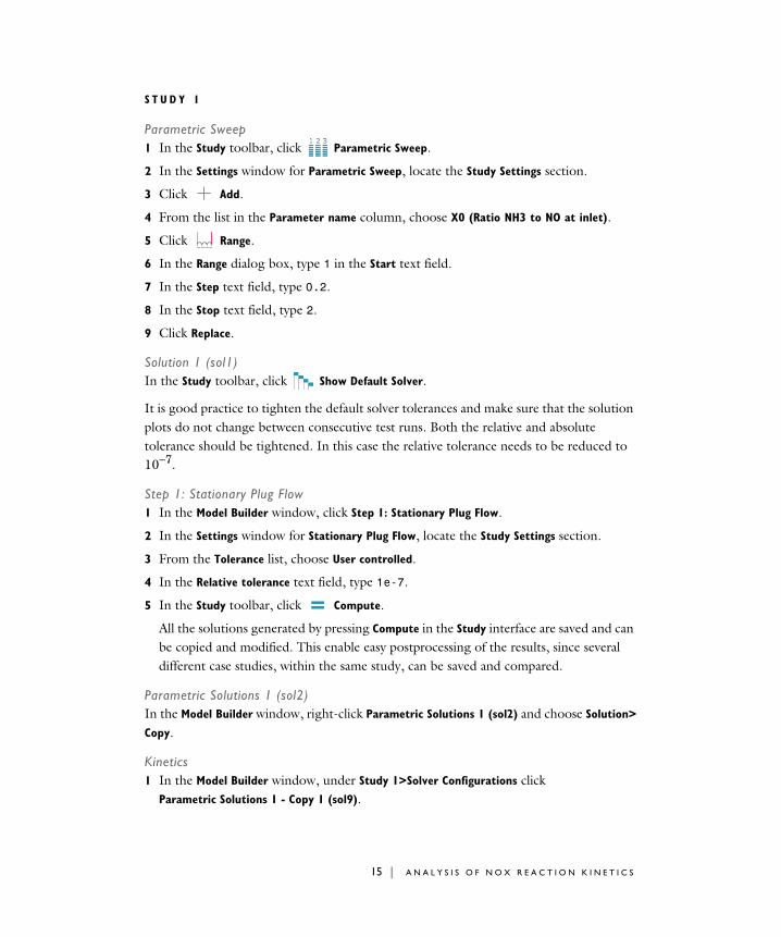
S T U D Y 1
Parametric Sweep1 In the Study toolbar, click Parametric Sweep.
2 In the Settings window for Parametric Sweep, locate the Study Settings section.
3 Click Add.
4 From the list in the Parameter name column, choose X0 (Ratio NH3 to NO at inlet).
5 Click Range.
6 In the Range dialog box, type 1 in the Start text field.
7 In the Step text field, type 0.2.
8 In the Stop text field, type 2.
9 Click Replace.
Solution 1 (sol1)In the Study toolbar, click Show Default Solver.
It is good practice to tighten the default solver tolerances and make sure that the solution plots do not change between consecutive test runs. Both the relative and absolute tolerance should be tightened. In this case the relative tolerance needs to be reduced to 10−7.
Step 1: Stationary Plug Flow1 In the Model Builder window, click Step 1: Stationary Plug Flow.
2 In the Settings window for Stationary Plug Flow, locate the Study Settings section.
3 From the Tolerance list, choose User controlled.
4 In the Relative tolerance text field, type 1e-7.
5 In the Study toolbar, click Compute.
All the solutions generated by pressing Compute in the Study interface are saved and can be copied and modified. This enable easy postprocessing of the results, since several different case studies, within the same study, can be saved and compared.
Parametric Solutions 1 (sol2)In the Model Builder window, right-click Parametric Solutions 1 (sol2) and choose Solution>
Copy.
Kinetics1 In the Model Builder window, under Study 1>Solver Configurations click
Parametric Solutions 1 - Copy 1 (sol9).
15 | A N A L Y S I S O F N O X R E A C T I O N K I N E T I C S
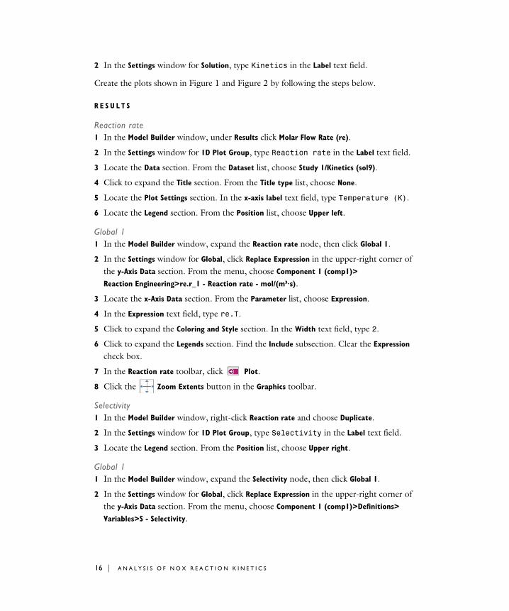
2 In the Settings window for Solution, type Kinetics in the Label text field.
Create the plots shown in Figure 1 and Figure 2 by following the steps below.
R E S U L T S
Reaction rate1 In the Model Builder window, under Results click Molar Flow Rate (re).
2 In the Settings window for 1D Plot Group, type Reaction rate in the Label text field.
3 Locate the Data section. From the Dataset list, choose Study 1/Kinetics (sol9).
4 Click to expand the Title section. From the Title type list, choose None.
5 Locate the Plot Settings section. In the x-axis label text field, type Temperature (K).
6 Locate the Legend section. From the Position list, choose Upper left.
Global 11 In the Model Builder window, expand the Reaction rate node, then click Global 1.
2 In the Settings window for Global, click Replace Expression in the upper-right corner of the y-Axis Data section. From the menu, choose Component 1 (comp1)>
Reaction Engineering>re.r_1 - Reaction rate - mol/(m³·s).
3 Locate the x-Axis Data section. From the Parameter list, choose Expression.
4 In the Expression text field, type re.T.
5 Click to expand the Coloring and Style section. In the Width text field, type 2.
6 Click to expand the Legends section. Find the Include subsection. Clear the Expression check box.
7 In the Reaction rate toolbar, click Plot.
8 Click the Zoom Extents button in the Graphics toolbar.
Selectivity1 In the Model Builder window, right-click Reaction rate and choose Duplicate.
2 In the Settings window for 1D Plot Group, type Selectivity in the Label text field.
3 Locate the Legend section. From the Position list, choose Upper right.
Global 11 In the Model Builder window, expand the Selectivity node, then click Global 1.
2 In the Settings window for Global, click Replace Expression in the upper-right corner of the y-Axis Data section. From the menu, choose Component 1 (comp1)>Definitions>
Variables>S - Selectivity.
16 | A N A L Y S I S O F N O X R E A C T I O N K I N E T I C S
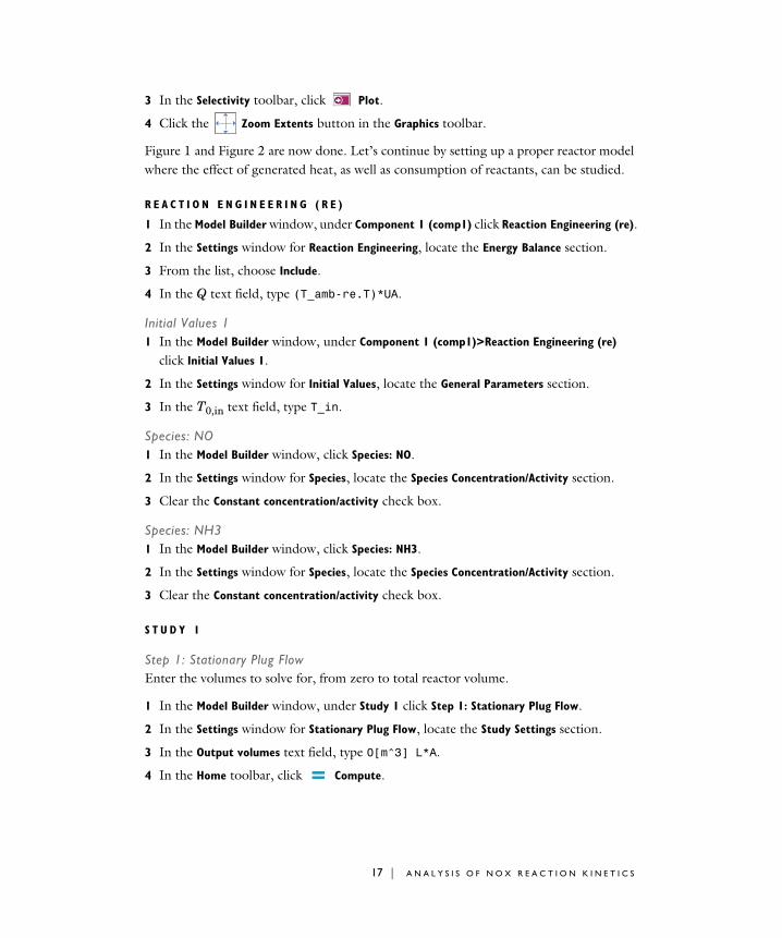
3 In the Selectivity toolbar, click Plot.
4 Click the Zoom Extents button in the Graphics toolbar.
Figure 1 and Figure 2 are now done. Let’s continue by setting up a proper reactor model where the effect of generated heat, as well as consumption of reactants, can be studied.
R E A C T I O N E N G I N E E R I N G ( R E )
1 In the Model Builder window, under Component 1 (comp1) click Reaction Engineering (re).
2 In the Settings window for Reaction Engineering, locate the Energy Balance section.
3 From the list, choose Include.
4 In the Q text field, type (T_amb-re.T)*UA.
Initial Values 11 In the Model Builder window, under Component 1 (comp1)>Reaction Engineering (re)
click Initial Values 1.
2 In the Settings window for Initial Values, locate the General Parameters section.
3 In the T0,in text field, type T_in.
Species: NO1 In the Model Builder window, click Species: NO.
2 In the Settings window for Species, locate the Species Concentration/Activity section.
3 Clear the Constant concentration/activity check box.
Species: NH31 In the Model Builder window, click Species: NH3.
2 In the Settings window for Species, locate the Species Concentration/Activity section.
3 Clear the Constant concentration/activity check box.
S T U D Y 1
Step 1: Stationary Plug FlowEnter the volumes to solve for, from zero to total reactor volume.
1 In the Model Builder window, under Study 1 click Step 1: Stationary Plug Flow.
2 In the Settings window for Stationary Plug Flow, locate the Study Settings section.
3 In the Output volumes text field, type 0[m^3] L*A.
4 In the Home toolbar, click Compute.
17 | A N A L Y S I S O F N O X R E A C T I O N K I N E T I C S
Parametric Solutions 1 (sol2)In the Model Builder window, right-click Parametric Solutions 1 (sol2) and choose Solution>
Copy.
Nonisothermal1 In the Model Builder window, under Study 1>Solver Configurations click
Parametric Solutions 1 - Copy 1 (sol22).
2 In the Settings window for Solution, type Nonisothermal in the Label text field.
The following steps generate Figure 3.
R E S U L T S
Molar flow rate NH3, Nonisothermal1 In the Model Builder window, under Results click Molar Flow Rate (re).
2 In the Settings window for 1D Plot Group, type Molar flow rate NH3, Nonisothermal in the Label text field.
3 Locate the Data section. From the Dataset list, choose Study 1/Nonisothermal (sol22).
4 Locate the Title section. From the Title type list, choose None.
5 Locate the Plot Settings section. Select the y-axis label check box.
6 In the associated text field, type Molar flow rate NH<sub>3</sub> (mol/s).
Global 11 In the Model Builder window, expand the Molar flow rate NH3, Nonisothermal node, then
click Global 1.
2 In the Settings window for Global, click Replace Expression in the upper-right corner of the y-Axis Data section. From the menu, choose Component 1 (comp1)>
Reaction Engineering>re.F_NH3 - Molar flow rate - mol/s.
3 Locate the Coloring and Style section. In the Width text field, type 2.
4 Locate the Legends section. Find the Include subsection. Clear the Expression check box.
5 In the Molar flow rate NH3, Nonisothermal toolbar, click Plot.
S T U D Y 1
Parametric Sweep1 In the Model Builder window, under Study 1 click Parametric Sweep.
2 In the Settings window for Parametric Sweep, locate the Study Settings section.
18 | A N A L Y S I S O F N O X R E A C T I O N K I N E T I C S

3 In the table, enter the following settings:
4 In the Home toolbar, click Compute.
Parametric Solutions 1 (sol2)In the Model Builder window, right-click Parametric Solutions 1 (sol2) and choose Solution>
Copy.
Nonisothermal 21 In the Model Builder window, under Study 1>Solver Configurations click
Parametric Solutions 1 - Copy 1 (sol32).
2 In the Settings window for Solution, type Nonisothermal 2 in the Label text field.
The following instructions generate Figure 4.
R E S U L T S
Selectivity, Nonisothermal1 In the Model Builder window, under Results click Temperature (re).
2 In the Settings window for 1D Plot Group, type Selectivity, Nonisothermal in the Label text field.
3 Locate the Data section. From the Dataset list, choose Study 1/Nonisothermal 2 (sol32).
4 Locate the Title section. From the Title type list, choose None.
5 Locate the Legend section. From the Position list, choose Middle right.
Global 11 In the Model Builder window, expand the Selectivity, Nonisothermal node, then click
Global 1.
2 In the Settings window for Global, click Replace Expression in the upper-right corner of the y-Axis Data section. From the menu, choose Component 1 (comp1)>Definitions>
Variables>S - Selectivity.
3 Locate the Coloring and Style section. In the Width text field, type 2.
4 Locate the Legends section. Find the Include subsection. Clear the Expression check box.
5 In the Selectivity, Nonisothermal toolbar, click Plot.
The following instructions generate Figure 5.
Parameter name Parameter value list Parameter unit
X0 (Ratio NH3 to NO at inlet) range(1.3,0.1,1.5)
19 | A N A L Y S I S O F N O X R E A C T I O N K I N E T I C S
Temperature, Nonisothermal1 In the Model Builder window, right-click Selectivity, Nonisothermal and choose Duplicate.
2 In the Settings window for 1D Plot Group, type Temperature, Nonisothermal in the Label text field.
Global 11 In the Model Builder window, expand the Temperature, Nonisothermal node, then click
Global 1.
2 In the Settings window for Global, click Replace Expression in the upper-right corner of the y-Axis Data section. From the menu, choose Component 1 (comp1)>
Reaction Engineering>re.T - Temperature - K.
3 In the Temperature, Nonisothermal toolbar, click Plot.
Graph Marker 11 Right-click Global 1 and choose Graph Marker.
2 In the Settings window for Graph Marker, locate the Display section.
3 From the Display list, choose Max.
4 Locate the Text Format section. In the Display precision text field, type 3.
5 Select the Include unit check box.
Global 21 Right-click Global 1 and choose Duplicate.
2 In the Settings window for Global, locate the y-Axis Data section.
3 Click Clear Table.
4 In the table, enter the following settings:
Graph Marker 11 In the Model Builder window, expand the Global 2 node, then click Graph Marker 1.
2 In the Settings window for Graph Marker, locate the Text Format section.
3 Clear the Include unit check box.
4 Click to expand the Coloring and Style section. From the Anchor point list, choose Lower right.
Temperature, Nonisothermal1 In the Model Builder window, click Temperature, Nonisothermal.
Expression Unit Description
(F_NO_in/vrate-re.c_NO)/(F_NO_in/vrate) 1 Conversion
20 | A N A L Y S I S O F N O X R E A C T I O N K I N E T I C S

2 In the Settings window for 1D Plot Group, locate the Data section.
3 From the Parameter selection (X0) list, choose From list.
4 In the Parameter values (X0) list, choose 1.3 and 1.5.
5 Locate the Plot Settings section. Select the Two y-axes check box.
6 In the table, select the Plot on secondary y-axis check box for Global 2.
7 In the Temperature, Nonisothermal toolbar, click Plot.
Global 21 In the Model Builder window, click Global 2.
2 In the Settings window for Global, locate the Coloring and Style section.
3 From the Color list, choose Cycle (reset).
4 Find the Line style subsection. From the Line list, choose Dashed.
21 | A N A L Y S I S O F N O X R E A C T I O N K I N E T I C S

22 | A N A L Y S I S O F N O X R E A C T I O N K I N E T I C S