analysis of process parameters of …ethesis.nitrkl.ac.in/4078/1/combine_thesis.pdfanalysis of...
TRANSCRIPT

ANALYSIS OF PROCESS PARAMETERS OF
PLASMA ARC CUTTING USING DESIGN OF
EXPERIMENT
A THESIS SUBMITTED IN PARTIAL FULFILLMENT
FOR THE REQUIREMENT FOR THE DEGREE OF
Master of Technology
In
Production Engineering
By
VIVEK SINGH
Department of Mechanical Engineering
National Institute of Technology
Rourkela
2011
ANALYSIS OF PROCESS PARAMETERS OF
PLASMA ARC CUTTING USING DESIGN OF
EXPERIMENT
A THESIS SUBMITTED IN PARTIAL FULFILLMENT
FOR THE REQUIREMENT FOR THE DEGREE OF
Master of Technology
In
Production Engineering
By
VIVEK SINGH
207ME209
Under the guidance of
Dr. K P MAITY
Professor, Department of Mechanical Engineering
Department of Mechanical Engineering
National Institute of Technology Rourkela

National Institute of Technology
Rourkela
CERTIFICATE
This is to certify that the thesis entitled, “ANALYSIS OF PROCESS
PARAMETERS OF PLASMA ARC CUTTING BY USING DESIGN OF
EXPERIMENT ” submitted by Vivek Singh (207ME209) in partial fulfilment of the
requirements for the award of Master of Technology Degree in Mechanical
Engineering with specialization in Production Engineering at the National Institute of
Technology, Rourkela (deemed University) is an authentic work carried out by him
under my guidance.
To the best of my knowledge, the matter embodied in the thesis has not submitted to
any other University/Institute for the award of any degree or diploma.
Dr. K P MAITY
Date: Dept. of Mechanical Engineering
National Institute of Technology
Rourkela – 769008

ACKNOWLEDGEMENT
I would like to express my deep sense of respect and gratitude toward my supervisor
Dr. K. P. Maity, who not only guided the academic/industrial project work but also
stood as a teacher and philosopher in realizing the imagination in pragmatic way, I
want to thank him for introducing me for the field of Optimization and giving the
opportunity to work under him. His optimism have provided an invaluable influence
on my career and outlook for the future. I consider it my good fortune to have got an
opportunity to work with such a wonderful person.
I express my gratitude to my co-guide Shri Sachin Bhartiya, Senior Engineer,
Fabrication Division, BHEL, Bhopal , and staff of Department of Fabrication
Division, BHEL, Bhopal for extending all possible help in carrying out the
experimental and dissertation work directly or indirectly. They have been great
source of inspiration to me and I thank them from bottom of my heart.
I like to express my gratitude to Shri U C Srivastava, GM, Project Division,
BHEL, Bhopal and Shri R N Edikie, AGM, Fabrication for his valuable advice
and permission for carrying out project work inside the plant premises. I am
especially indebted to my parents for their love, sacrifices and support. They are my
teachers after I came to this world and have set great example for me about how to
live, study and work.
VIVEK SINGH
207ME209

CONTENTS
TITLE PAGE NO.
ABSTRACT
LIST OF TABLES
LIST OF FIGURES
LIST OF GRAPHS
1. INTRODUCTION
1.1 Overview 2
1.2 Process Description 4
1.3 Introduction to Problem 6
1.3.1 Problem Statement 7
1.4 Objectives 8
1.5 Scope 9
1.6 Introduction to PAC 10
1.7 Design of Experiment (DOE) 11
1.8 Significance of Findings 14
1.9 Summary 14
2. LITERATURE REVIEW
2.1 Principle of Plasma Arc Cutting 17
2.1.1 Shielding & Cutting Gases for Plasma Cutting 22
2.1.2 Plasma Gas Selection 23
2.1.3 Secondary Gas Selection for Plasma Cutting 24
2.2 Plasma Cutting Capability 26
2.3 System 27

2.4 Arc Starting Circuit 28
2.5 Plasma Torch 29
2.5.1 Torch Design 30
2.5.2 Torch Consumables 31
2.6 Taguchi Design Overview 34
2.7 What is Taguchi Design? 36
3. PROJECT METHODOLOGY
3.1 Test Specimen Preparation 38
3.2 Material 38
3.3 Equipments 40
3.4Design Factors 43
3.5 Plasma Arc Cutting Response 44
3.5.1 Material Removal Rate (MRR) 45
3.5.2 Surface Roughness (Ra) 45
4. DESIGN OF STUDY
4.1 Outline of Thesis Work 48
4.2 Design of Experiment 49
4.3 Selection of Orthogonal Array & Parametric Assignment 50
4.3.1 Standard L 16 Array 51
4.4 Signal to Noise (S/N) Ratio 52
4.5 Analysis of Variance (ANOVA) 54
4.5.1 ANOVA Formulas 55

5. EXPERIMENTAL ANALYSIS
5.1 Experiment Layout 58
5.2 Experimental Result for MRR 61
5.3 Experimental Result for SR (Ra) 63
5.4ANOVA Calculations 64
5.5 Confirmation Test 66
5.5.1 Prediction of Optimum MRR 68
5.5.2 Prediction of Optimum SR (Ra) 69
5.5.3 Summary 71
6. MATHEMATICAL MODELLING
6.1 Introduction to Regression Analysis 73
6.1.1 Bivariate Regression 73
6.1.2 The Least Square Method 74
6.1.3 Residual 75
6.1.4 Sampling Error 75
6.1.5 Coefficient of Determination (R2) 76
6.1.6 Multicollinearity 76
6.2 First order Linear Model for MRR 77
6.3 First order Linear Model for SR (Ra) 79
7. RESULT CONCLUSION & FUTURE SCOPE
7.1 Summary 82
7.2 Results 83
7.3 Discussions 84
7.4 Conclusion 85
7.5 Scope of Future Work 86
BIBLIOGRAPHY
� Journal Reference 87
� Book Reference 89
� Web Reference 90
MINITAB 15 SOFTWARE ANALYSIS SHEETS
� Experimental Layout for MRR and SR
� Linear Model Analysis of MRR
� Main Effect Plot for MRR
� Regression Analysis for MRR
� Normal Probability Plot of MRR (Residuals)
� Linear Model Analysis for Surface Roughness (Ra)
� Main Effect Plot for Ra
� Regression Analysis for Ra
� Normal Probability plot for Ra

LIST OF TABLES
Page No.
Table 2.1 Summary Table for Plasma Gas Selection 25
Table 3.1 Composition Ranges for 316 grades of SS 39
Table 3.2 Mechanical Properties of 316 Grade SS 39
Table 3.3 Technical Features of Plasma Machine 40
Table 4.1 Fixed Machining Parameters 50
Table 4.2 Parametric Level Assignment 50
Table 4.3 Experimental Layout in Coded Factor Levels 58
Table 5.1 Values of Variables at Different Level 58
Table 5.2 Calculation Sheet for MRR and Surface Roughness (Ra) 59
Table 5.3 Experimental Layout & S/N Ratios (In Actual Factor Levels) 60
Table 5.4 ANOVA Table for MRR 64
Table 5.5 ANOVA Table for Surface Roughness (Ra) 65
Table 5.6 Response Table for S/N Ratio of MRR 66
Table 5.7 Response Table for S/N Ratio of SR (Ra) 67
Table 5.8 Confirmation Test Result for MRR 70
Table 5.9 Confirmation Test Result for Surface Roughness (Ra) 70
Table 5.10 Summary Table for Results 71
Table 7.1 Result Before & After Optimisation 83

LIST OF FIGURES
Page No.
Figure 1.1 PAC Arc Cut Away 4
Figure 1.2 TIG and Plasma Arc 5
Figure 2.1 Principle of Plasma Cutting 18
Figure 2.2 Air Plasma 21
Figure 2.3 Plasma Arc Setup 26
Figure 2.4 Plasma Arc Cutter System 27
Figure 2.5 Torch Stand Off 31
Figure 2.6 Torch Break Down 31
Figure 2.7 Electrode 32
Figure 2.8 Swirl Ring 33
Figure 2.9 Tip 33
Figure 3.1 Test Specimen 38
Figure 3.2 DC Power Supply 42

LIST OF GRAPHS
Page No.
Graph 5.1 Main Effect Plot for S/N Ratio of MRR 61
Graph 5.2 Main Effect Plot for Mean of MRR 62
Graph 5.3 Main Effect Plot for S/N Ratio of SR (Ra) 63
Graph 6.1 Normal Probability Plot for Residuals of MRR 78
Graph 6.2 Normal Probability Plot for Residuals of SR (Ra) 80

ABSTRACT
In last forty years there is tremendous research in machining and development in
technology. With increase in competition in market and to attain high accuracy now a
days the nonconventional machining are become lifeline of any industry. One of the
most important non conventional machining methods is Plasma Arc Machining. Its
high accuracy, finishing, ability of machining any hard materials and to produce
intricate shape increases its demand in market.
In thesis work literature has been studied in context to parametric optimization of
Plasma Arc Cutting Machine. In order to attain target and optimum results, Taguchi
method employed. The appropriate orthogonal array has been selected as per number
of factors and there levels to perform minimum experimentation.
The work pieces of Stainless Steel (316 L) materials were used for experiment
purpose. The optimum value has been determined with the help of main effect plot
and ANOVA table. The Regression equation for MRR and Surface Roughness (Ra)
has been developed with the help of Minitab 15 Software. Confirmation test have
done to confirm the value estimated through the software.
The Confirmation for MRR run was done by using the setting of 5.0 bar (Gas
pressure), 150 A (Current flow rate), 600 mm/min (cutting speed) and 4.0 mm (arc
gap). The optimum parameter level for Surface Roughness are 6.0 Bar (Gas
Pressure), 150 A (Current), 400 mm/min (Cutting Speed) and 2 mm (Arc Gap).
Experimental results are provided to confirm the effectiveness of this approach. After
the confirmation the MRR value was 0.8331 g/sec and Ra 2.635µm. Error within 10
% was allowed.

CHAPTER 1
INTRODUCTION

1. INTRODUCTION
1.1 OVERVIEW
The topic for the thesis writing is the Analysis of Process Parameters of Plasma Arc
Cutting Using Design of Experiment Techniques. The focus on this project is to
obtain an optimum condition (setting) to obtain maximum MRR and minimum the
surface roughness (SR).
A person doesn't need to be a physicist or chemist to understand the Plasma Arc
Cutting (PAC) and Gouging process. There are four states in which physical matter
may be found: solid, liquid, gas or plasma. Changes from one physical state to
another occur, by either supplying or subtracting energy, in the form of heat.
Water can be used as an example of these four states of matter. In the solid state it is
ice at temperatures of 0 degrees Celsius or colder. With the addition of heat the ice
melts and changes to water, the liquid state. The addition of more heat to
temperatures of 212 degrees F. (100 degrees C.) or hotter) converts this liquid to its
gaseous state, steam.
The fourth state of matter, plasma, looks and behaves like a high temperature gas,
but with an important difference; it conducts electricity. The plasma arc is the result
of the electrical arcs heating of any gas to a very high temperature so that its atoms
are ionized (an electrically charged gas due to an unequal number of electrons to
protons) and enabling it to conduct electricity. The major difference between a
neutral gas and plasma is that the particles in plasma can exert electromagnetic
forces on one another.

If you happen to be reading this by the light emitted by a fluorescent lamp you see
plasma in action. Within the glowing tube of the lamp is plasma consisting of low
pressure mercury or sodium vapour. It is ionized by a high voltage across electrodes
at the ends of the tube and conducts an electric current which causes the plasma to
radiate which in turn causes the phosphor coating on the inner surface of the tube to
glow [19] .
For many years, oxy-acetylene cutting was often the process of choice for quickly
cutting through steel plate. Over the past few years plasma cutting has pretty much
taken over, for some very good reasons to perhaps most importantly. A plasma
cutter will cut through any metal that is electrically conductive. That means that one
unit will cut steel, stainless steel, aluminium, copper, bronze, and brass etc.
The plasma jet that does the cutting is hotter and narrower than an oxy-acetylene
flame, so the kerfs width is smaller, and can get cleaner cuts. This makes plasma
cutting particularly well-suited for cutting sheet metal, a task the oxy-acetylene
cutting torch is not particularly well-suited for since it leaves a lot of slag on the
edges. The extremely tight focus of the plasma arc tends to minimize heat distortion
in the cut parts, as well.

1.2 PROCESS DESCRIPTION Plasma cutting is a process that is used to cut steel and other metals (or sometimes
other materials) using a plasma torch. In this process, an inert gas (in some units,
compressed air) is blown at high speed out of a nozzle, at the same time an electrical
arc is formed through that gas from the nozzle to the surface being cut, turning some
of that gas to plasma. The plasma is sufficiently hot to melt the metal being cut and
moves sufficiently fast to blow molten metal away from the cut. Plasma can also be
used for plasma arc welding and other applications [24].
FIG. 1.1 PAC Arc Cut-Away
The plasma arc torch has a space or area surrounding the circumference of the
electrode, between the inside circumference of the torch tip or nozzle. It is in this
chamber that the plasma gas is heated and ionized. This heating causes the plasma
gas to greatly expand in volume and pressure. The plasma gas exits from the
constricting orifice of the torch nozzle or tip at very high speeds and temperatures;
up to 30,000 degrees F. (16,000 degrees C.) and 6000 m/s (20,000 ft/s). The

intensity and velocity of the plasma is determined by several variables including the
type of gas, its pressure & volume, the flow pattern, the amount of electric current,
the size and shape of the constricting tip or nozzle orifice, and the tip to work
distance.
FIG. 1.2 TIG and Plasma Arcs
The PAC process uses this high temperature, constricted, high velocity jet of ionized
gas exiting from the constricting orifice of the torch tip to melt a much localized
area and remove the molten material from the metal being cut by the force of the
plasma jet. The force of the arc pushes the molten metal through the work piece and
severs the material. Extremely clean and accurate cuts are possible with PAC.
Because of the tightly focused heat energy, there's very little warping, even when
cutting thin gauge sheet metal thickness. PAC also offers quality gouging and
piercing capabilities [17].

1.3 INTRODUCTION TO PROBLEM
Advanced materials exhibit very excellent technical properties. However, the high
cost of both raw materials and processing limit their use. Alternatively, advanced
machining such as Plasma Arc Cutting is normally used. Advanced material such as
nickel-base alloys, titanium alloys and stainless steel can be used as the work piece
in this type of cutting.
A torch in which temperatures as high as 30,000°C are achieved by injecting a
plasma gas tangentially into an electric arc formed between electrodes in a chamber;
the resulting vortex of hot gases emerges at very high speed through a hole in the
negative electrode, to form a jet for welding, spraying of molten metal, and cutting
of hard rock or hard metals [25].
The plasma arc also cuts ferrous and non-ferrous metals much faster than an Oxy-
Fuel torch or abrasive saws, with low or no heat affected zone, especially on thinner
metals. A clean cut with little or no dross means less time and money is required to
finish the work piece. Parts are virtually weld-ready.
With plasma cutting, less preparation work is required. A plasma arc is hot enough
to burn through most surface coatings such as paint and rust and still provides
excellent cutting results. With plasma cutting, there is minimal heat input and
distortion of the metal as there is with jigsaws or cutting shears. For applications
where difficult shapes are being handled or cut, such as ventilation ductwork
(HVAC), tanks or vessels, plasma cutting offers considerable advantage since no
fixturing is required [25].
The feasibility and effectiveness needs to be proven by experiment and by using
Taguchi Method of the processing parameter to obtain the best factors combination
(MRR and Surface Roughness).
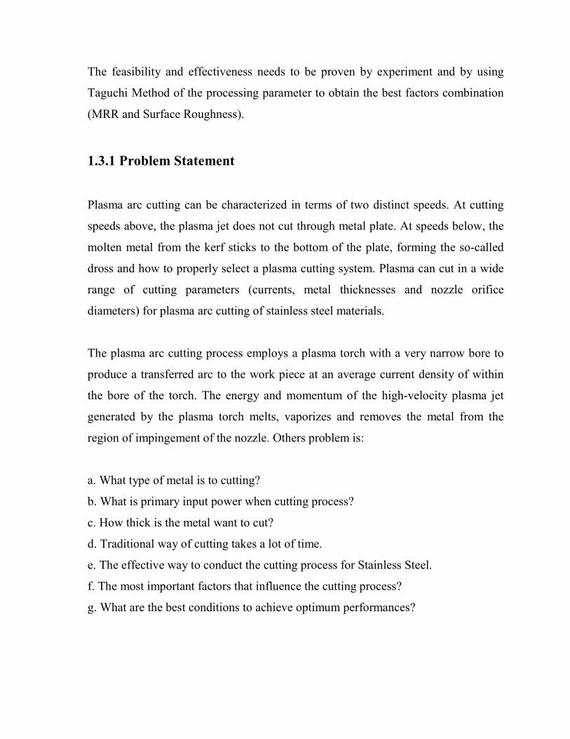
1.3.1 Problem Statement
Plasma arc cutting can be characterized in terms of two distinct speeds. At cutting
speeds above, the plasma jet does not cut through metal plate. At speeds below, the
molten metal from the kerf sticks to the bottom of the plate, forming the so-called
dross and how to properly select a plasma cutting system. Plasma can cut in a wide
range of cutting parameters (currents, metal thicknesses and nozzle orifice
diameters) for plasma arc cutting of stainless steel materials.
The plasma arc cutting process employs a plasma torch with a very narrow bore to
produce a transferred arc to the work piece at an average current density of within
the bore of the torch. The energy and momentum of the high-velocity plasma jet
generated by the plasma torch melts, vaporizes and removes the metal from the
region of impingement of the nozzle. Others problem is:
a. What type of metal is to cutting?
b. What is primary input power when cutting process?
c. How thick is the metal want to cut?
d. Traditional way of cutting takes a lot of time.
e. The effective way to conduct the cutting process for Stainless Steel.
f. The most important factors that influence the cutting process?
g. What are the best conditions to achieve optimum performances?
1.4 OBJECTIVES
This project was developed to study about the plasma arc cutting parameter in
smooth cutting using straight polarity process. The main purposes of this project are
listed below:
a) To study about the influence of Plasma Arc Cutting Parameters on Stainless
Steel.
b) To design a series of experiment using the help of Design of Experiments (DOE)
layout in order to study about Plasma Arc Cutting (PAC).
c) To study about the best combination of solution for maximizing the Material
Removal Rate (MRR) and for minimizing the Surface Roughness (µm) with
Taguchi Method .

1.5 SCOPE
Generally these projects will be developing within the scopes below:
1. This project focuses on the optimization of cutting parameters of Plasma Arc
Cutting (PAC).
2. The material used to cut was Stainless Steel of specification ASTM A240
TP316 L.
3. Design of Experiments (DOE) layout will be used for testing and analyzing
with Taguchi Method .
4. All of data was analyzed by using Minitab 15 Software to produce the best
combination setting in plasma cutting for Stainless Steel.
5. The machine used will Silverin CNC Plasma Cutting Machine with Sharp line,
Bombay make Burney 10 LCD to perform the machining operation.

1.6 INTRODUCTION TO PAC
Plasma arc cutting is not quite as involved as welding. The manner in cut the
work piece will vary depending on the output of your plasma arc cutting machine
and the thickness of material.
With engineering advances in PAC equipment, all metals that conduct electricity,
whether they are common or exotic metals, can be cut economically with one
process. Since the plasma arc cutting process is capable of hand-held or machine
torch cutting metals ranging from thin gauge aluminium to 5-60 mm carbon or
stainless steel. It can be used in many applications, including stack cutting,
bevelling, shape cutting, gouging, and piercing in all positions. The PAC process is
used in industries such as metal fabrication, construction, maintenance, metal
salvage (scrap and recycling), automotive repair, metal art and sculpting.
When cutting metals at and below a machine's rated thickness, fix the gun at a 90-
deg angle to the work piece. Make sure to take note of a machine's mm per minute
capabilities on varying thicknesses, as that gives an idea of how fast to move across
the cutting surface. When cutting materials at the rated size and above, it's
recommended to slightly tilt torch into the work piece.
When needing to make multiple passes on a work piece to properly cut it and simply
need a more powerful plasma cutting machine. Pay close attention to the machine's
capabilities.

1.7 DESIGN OF EXPERIMENTS (DOE)
Design of Experiments (DOE) is a powerful statistical technique introduced by R.A.
fisher in England in 1920s to study the effect of multiple variables simultaneously
DOE can highly effective when:
a). Optimize product and process design , study the effect of multiple factor on
process.
b). Study the influence of individual factors on the performance and determine
which factor has more influence, and which one has less. It can also find which
factor should have higher tolerance and which tolerance should be relaxed.
In industry, designed experiments can be used to systematically investigate the
process or product variables that influence product quality. After you identify the
process conditions and product components that influence product quality, you can
direct improvement efforts to enhance a product's manufacturability, reliability,
quality, and field performance.
Because resources are limited, it is very important to get the most information from
each experiment you perform. Well designed experiments can produce significantly
more information and often require fewer runs than haphazard or unplanned
experiments. In addition, a well-designed experiment will ensure that you can
evaluate the effects that you have identified as important [20].
.
Designed experiments are often carried out in four phases:
a) Planning,
b) Screening (also called process characterization), c) Optimization, and d) Verification.

Taguchi methods are most recent additions of tool kit design process for
manufacturing engineers and quality assurance experts. In contrast to stastical
process control which attempt to control the factors that adversely affect the quality
of production. The significance of beginning quality assurance with an improved
process or product design is not difficult to gauge. Taguchi method systematically
reveals the complex cause and effect relationship between design parameter and
performance.
These lead to building quality performance into process and product before actual
production begins .Taguchi method have rapidly attained prominence because
wherever they have been applied, they lead to the major reductions into process and
products before actual production begins .The foundation of quality depend upon
two premises :
1. Society incurs a loss any time the performance of product is not on target.
2. Product and process design require a systematic development, progressing
stepwise through system design, parametric design and finally tolerance design.
The first point suggests that whenever the performance of a product deviates from
its target performance, society suffer loss. Such a loss has two components: The
manufacture incurs a loss when he repairs or rectified return or rejected product.
The second point aims at quality engineering, a discipline that aims at engineering
not only function but also quality performance into products and process .
The following seven points highlight the distinguish feature of Taguchi’s approach
which aimed at assuring quality:
1. Taguchi defined the term quality as the deviation from on target performance
which
appears to be first paradox. According to him the quality of a manufactured product
is the total loss generated by that product to the society from the time it is shipped.
2. In a competitive economy continuous improvement (CQI) and cost reduction are
necessary.
3. A CQI programmed include continuous reduction in the variation of product
performance characteristic in their target values.
4. Customer loss attribute to the product performance variation is often proportional
to the square of the deviation performance characteristic from its target value.
5. The finally quality and cost of a product manufactured depends primarily on the
engineering design of the product and its manufacturing process.
6. Variation in the product depends primarily on the engineering design of the
product and its manufacturing process.
7. Statically planned experiments can efficiently and reliably identify the settings of
the product and process parameters that reduce performance variations.
1.8 SIGNIFICANCE OF FINDINGS
From the thesis writing, it is important to get the best setting of Plasma Arc
Cutting machine to maximize the Metal Removal Rate (MRR) and minimize the
Surface Roughness (Ra) response during the advance material cutting process. From
the result of the experiments using the Taguchi Method by Minitab 15 Software for
Design of Experiments, the best combination of factors can be obtained, and the
conclusions for the works that have been carried out can be determined.
1.9 SUMMARY
As a conclusion, the introduction to the problem has been specified. From the
problem that arises, the solution has to be carried out. The objectives and the scopes
have been determined in order to solve the problems

CHAPTER 2
LITERATURE REVIEW
2. LITERATURE REVIEW
Plasma cutting is a process that is used to cut steel and other metals (or sometimes
other materials) using a plasma torch. In this process, an inert gas (Argon) is blown at
high speed out of a nozzle and at the same time an electrical arc is formed through
that gas from the nozzle to the surface being cut, turning some of that gas to plasma.
The plasma is sufficiently hot to melt the metal being cut and moves sufficiently fast
to blow molten metal away from the cut. Plasma can also be used for plasma arc
welding and other applications [24].
Plasma is typically an ionized gas. Plasma is considered to be a distinct state of
matter, apart from gases, because of its unique properties. Ionized refers to presence
of one or more free electrons, which are not bound to an atom or molecule. The free
electric charges make the plasma electrically conductive so that it responds strongly
to electromagnetic fields [27].
The Arc type uses a two cycle approach to producing plasma. First, a high-voltage,
low current circuit is used to initialize a very small high intensity spark within the
torch body, thereby generating a small pocket of plasma gas. This is referred to as the
pilot arc. The pilot arc has a return electrical path built into the torch head. The pilot
arc will maintain until it is brought into proximity of the work piece where it ignites
the main plasma cutting arc. Plasma arcs are extremely hot and are in the range of
15,000 degrees Celsius.
Oxy fuel cuts by burning, or oxidizing, the metal it is severing. It is therefore limited
to steel and other ferrous metals which support the oxidizing process.

Metals like aluminium and stainless steel form an oxide that inhibits further
oxidization, making conventional oxyfuel cutting impossible. Plasma cutting,
however, does not rely on oxidation to work, and thus it can cut aluminium, stainless
and any other conductive material. While different gasses can be used for plasma
cutting, most people today use compressed air for the plasma gas. In most shops,
compressed air is readily available, and thus plasma does not require fuel gas and
compressed oxygen for operation.
Plasma cutting is typically easier for the novice to master, and on thinner materials,
plasma cutting is much faster than oxyfuel cutting. However, for heavy sections of
steel (1inch and greater), oxyfuel is still preferred since oxyfuel is typically faster
and, for heavier plate applications, very high capacity power supplies are required for
plasma cutting applications [28] .
2.1 PRINCIPLE OF PLASMA ARC CUTTING
This process uses a concentrated electrical arc which melts the material through a
high-temperature plasma beam. All conductive materials can be cut. Plasma cutting
units with cutting currents from 20 to 1000 amperes to cut plates with inert gas, 5 to
160 mm thicknesses. Plasma gases are compressed air, nitrogen, oxygen or argon/
hydrogen to cut mild and high alloy steels, aluminium, copper and other metals and
alloys [4].
The plasma arc process has always been seen as an alternative to the oxy-fuel
process. In this part of the series the process fundamentals are described with
emphasis being placed on the operating features and the advantages of the many
process variants.

Fig 2.1 The principle of the plasma cutting
The plasma is additionally tied up by a water-cooled nozzle. With this energy
densities up to 2x10⁶ W/cm2 inside of the plasma beam can be achieved. Because of
the high temperature the plasma expands and flows with supersonic velocity speed to
the work piece (anode). Inside the plasma arc temperatures of 30 000oC can arise,
that realize in connection with the high kinetic energy of the plasma beam and
depending on the material thickness very high cutting speeds on all electrically
conductive materials.
The term for advisable state of plasma arc is called stability of arc too. The stability
of arc is keeping the plasma jet in desired form. It is possible to be provided by [4]:
a) Shape of Plasma Torch,
b) Streaming Jet,
c) Water.
We must monitor these parameters:
� Temperature and electrical conducting,
� Density of plasma jet,
� Diameter of plasma beam,
� Degree of the plasma beam focusing in output from nozzle.
For the cutting process first of all a pilot arc ignition by high voltage between nozzle
and cathode takes place. This low- energy pilot arc prepares by ionization in parts the
way between plasma torch and work piece. When the pilot arc touches the work piece
(flying cutting, flying piercing), the main arc will start by an automatic increase in
power
The basic principle is that the arc formed between the electrode and the work piece is
constricted by a fine bore, copper nozzle. This increases the temperature and velocity
of the plasma emanating from the nozzle. The temperature of the plasma is in excess
of 20 000°C and the velocity can approach the speed of sound. When used for
cutting, the plasma gas flow is increased so that the deeply penetrating plasma jet cuts
through the material and molten material is removed in the efflux plasma.
The process differs from the oxy-fuel process in that the plasma process operates by
using the arc to melt the metal whereas in the oxy-fuel process, the oxygen oxidizes
the metal and the heat from the exothermic reaction melts the metal. Thus, unlike the
oxy-fuel process, the plasma process can be applied to cutting metals which form
refractory oxides such as stainless steel, aluminium, cast iron and non-ferrous alloys.
The power source required for the plasma arc process must have a drooping
characteristic and a high voltage. Although the operating voltage to sustain the
plasma is typically 100 to 160V, the open circuit voltage needed to initiate the arc can

be up to 400V DC. On initiation, the pilot arc is formed within the body of the torch
between the electrode and the nozzle. For cutting, the arc must be transferred to the
work piece in the so-called 'transferred' arc mode. The electrode has a negative
polarity and the work piece a positive polarity so that the majority of the arc energy
(approximately two thirds) is used for cutting.
In the conventional system using a tungsten electrode, the plasma is inert, formed
using either argon, argon-H2 or nitrogen. However, as described in Process variants,
oxidizing gases, such as air or oxygen can be used but the electrode must be copper
with hafnium. The plasma gas flow is critical and must be set according to the current
level and the nozzle bore diameter. If the gas flow is too low for the current level, or
the current level too high for the nozzle bore diameter, the arc will break down
forming two arcs in series, electrode to nozzle and nozzle to work piece.
The effect of ‘double arcing’ is usually catastrophic with the nozzle melting. The
quality of the plasma cut edge is similar to that achieved with the oxy fuel process.
However, as the plasma process cuts by melting, a characteristic feature is the greater
degree of melting towards the top of the metal resulting in top edge rounding, poor
edge squareness or a bevel on the cut edge. As these limitations are associated with
the degree of constriction of the arc, several torch designs are available to improve
arc constriction to produce more uniform heating at the top and bottom of the cut.
The process variants have principally been designed to improve cut quality and arc
stability, reduce the noise and fume or to increase cutting speed. The inert or
uncreative plasma forming gas (argon or nitrogen) can be replaced with air but this
requires a special electrode of hafnium or zirconium mounted in a copper holder, by
shearing . The air can also replace water for cooling the torch. The advantage of an
air plasma torch is that it uses air instead of expensive gases. It should be noted that

although the electrode and nozzle are the only consumables, hafnium tipped
electrodes can be expensive compared with tungsten electrodes.
Figure 2.2: Air Plasma
This relatively new process differs from conventional, dry plasma cutting in that
water is injected around the arc. The net result is greatly improved cut quality on
virtually all metals, including mild steel. Today, because of advances in equipment
design and improvement in cut quality, previously unheard of applications, such as
multiple torches cutting of mild steel, are becoming common place [31].

2.1.1 Shielding and Cutting Gases for Plasma Cutting
Inert gases such as argon, helium, and nitrogen (except at elevated temperatures) are
used with tungsten electrodes. Air may be used for the cutting gas when special
electrodes made from water-cooled copper with inserts of metals such as hafnium are
used. Recently, PAC units shielded by compressed air have been developed to cut
thin-gauge materials.
Almost all plasma cutting of mild steel is done with one of three gas types:
1. Nitrogen with carbon dioxide shielding or water injection (mechanized)
2. Nitrogen-oxygen or air
3. Argon-hydrogen and nitrogen-hydrogen mixtures
The first two have become standard for high-speed mechanized applications. Argon-
hydrogen and nitrogen-hydrogen (20 to 35 percent hydrogen) are occasionally used
for manual cutting, but the formation of dross, a tenacious deposit of resolidified
metal attached at the bottom of the cut, is a problem with the argon blend. A possible
explanation for the heavier, more tenacious dross formed with argon is the greater
surface tension of the molten metal. The surface tension of liquid steel is 30 percent
higher in an argon atmosphere than in one of nitrogen.
Air cutting gives a dross similar to that formed in a nitrogen atmosphere. The plasma
jet tends to remove more metal from the upper part of the work piece than from the
lower part. This results in nonparallel cut surfaces that are generally wider at the top
than at the bottom. The use of argon-hydrogen, because of its uniform heat pattern or
the injection of water into the torch nozzle (mechanized only), can produce cuts that
are square on one side and bevelled on the other side. For base metal over 3 inches
thick, argon-hydrogen is frequently used without water injection [17].

2.1.2 Plasma Gas Selection
Air Plasma
1. Mostly used on ferrous or carbon based materials to obtain good quality a
faster cutting speeds.
2. Only clan, dry air is recommended to use as plasma gas. Any oil or moisture in
the air supply will substantially reduce torch parts life.
3. Air Plasma is normally used with air secondary.
Nitrogen Plasma
1. Can be used in place of air plasma with air secondary.
2. Provides much better parts life than air
3. Provides better cut quality on non-ferrous materials such as stainless steel and
aluminium.
4. A good clean welding grade nitrogen should be used.
Argon/Hydrogen Plasma
1. A 65% argon/35% hydrogen mixture should be used.
2. Recommended use on 19mm and thicker stainless steel. Recommended for
12mm and thicker non-ferrous material. Ar/H2 is not normally used for thinner
non-ferrous material because less expensive gases can achieve similar cut
quality.
3. Provides faster cutting speeds and high cut quality on thicker material to offset
the higher cost of the gas.
4. Poor quality on ferrous materials.
Oxygen Plasma
1. Oxygen is recommended for cutting ferrous metals.
2. Provides faster cutting speeds.
3. Provides very smooth finishes and minimizes nitride build-up on cut surface
(nitride build-up can cause difficulties in producing high quality welds if not
removed).
2.1.3 Secondary Gas Selection for Plasma Cutting
Air Secondary
1. Air secondary is normally used when operating with air plasma and
occasionally with nitrogen plasma.
2. Inexpensive - reduces operating costs
3. Improves cut quality on some ferrous materials
CO2 Secondary
1. CO2 secondary is used with nitrogen or Ar/H2 plasma.
2. Provides good cooling and maximizes torch parts life.
3. Usable on any ferrous or non-ferrous material
4. May reduce smoke when used with Ar/H2 plasma.
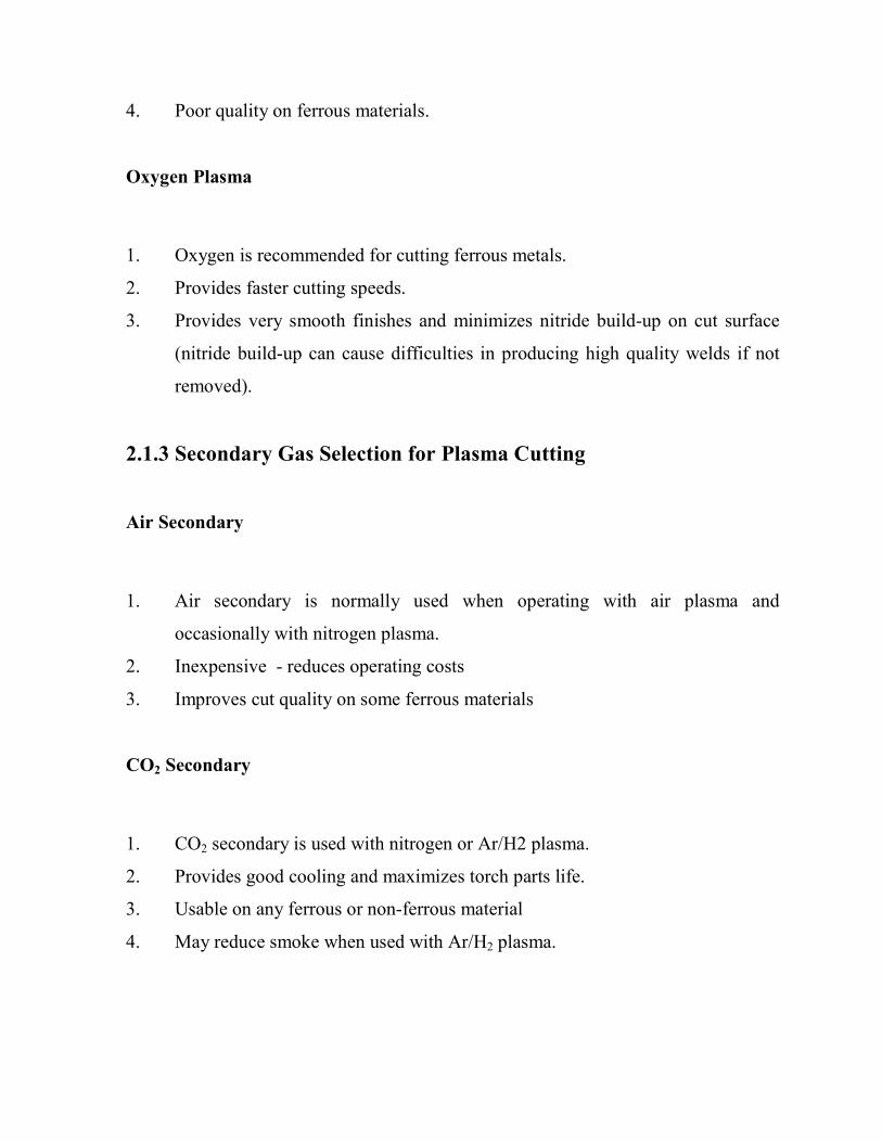
Table 2.1 SUMMARY TABLE FOR GASE SELECTION
Gas Material
Thickness
Material
Carbon Steel Stainless
Steel
Aluminium
Air Plasma
Air Secondary
Gage
Gage to 12mm
12mm and Up
Good / Excellent
Excellent
Excellent
Good / Excellent
Good
Fair
Good / Excellent
Good
Fair
Nitrogen Plasma
Air Secondary
Or CO2 Secondary
Gage
Gage to 12mm
12mm and Up
Good / Excellent
Good / Excellent
Good / Excellent
Good / Excellent
Good / Excellent
Good / Excellent
Good / Excellent
Good / Excellent
Good / Excellent
Ar/H2 Plasma
N2 or CO2
Secondary
Gage to 6mm
6mm to 30mm
12mm and Up
NR
NR
NR
NR
Good
Good / Excellent
NR
Excellent
Excellent

2.2 PLASMA CUTTING CAPABILITY
Plasma is an effective means of cutting thin and thick materials alike. Hand held
torches can usually cut up to 2 in (48 mm) thick steel plate, and stronger computer-
controlled torches can pierce and cut steel up to 12 inches (300 mm) thick. Formerly,
plasma cutters could only work on conductive materials, however new technologies
allow the plasma ignition arc to be enclosed within the nozzle thus allowing the cutter
to be used for non-conductive work pieces. Since plasma cutters produce a very hot
and much localized cone to cut with they are extremely useful for cutting sheet metal
in curved or angled shapes.
In this work, Plasma Arc Cutter was utilized to perform Stainless Steel (316 L)
material cutting. The system and the process are the important elements when
utilizing plasma arc cutting. It is important to know current plasma arc cutting
research areas to plan the direction of this work so that this work would contribute
information that will be useful in future.
Fig 2.3Plasma Arc Setup

2.3 SYSTEM
Plasma arc cutting can increase the speed and efficiency of both sheet and plate metal
cutting operations. Manufacturers of transportation and agricultural equipment, heavy
machinery, aircraft components, air handling equipment, and many other products
have discovered its benefits. Basically Plasma Arc Cutter comprises of 8 major parts
such as air compressor, AC plug, power supply, plasma torch, ground clamp,
electrode, nozzle and workpiece [17].
Figure 2.4 : Plasma Arc Cutter System
2.4 ARC STARTING CIRCUIT
The arc starting circuit is a high frequency generator circuit that produces an AC
voltage of 5,000 to 10,000 volts at approximately 2 megahertz. This voltage is used to
create a high intensity arc inside the torch to ionize the gas, thereby producing the
plasma [35].
2.5 PROCESS
The basic plasma arc cutting system consists of a power supply, an arc starting circuit
and a torch. These system components provide the electrical energy, ionization
capability and process control that is necessary to produce high quality, highly
productive cuts on a variety of different materials.
The power supply is a constant current DC power source. The open circuit voltage is
typically in the range of 240 to 400 VDC. The output current (amperage) of the
power supply determines the speed and cut thickness capability of the system. The
main function of the power supply is to provide the correct energy to maintain the
plasma arc after ionization.
The arc starting circuit is a high frequency generator circuit that produces an AC
voltage of 5,000 to 10,000 volts at approximately 2 megahertz. This voltage is used to
create a high intensity arc inside the torch to ionize the gas, thereby producing the
plasma.
The Torch serves as the holder for the consumable nozzle and electrode, and provides
cooling (either gas or water) to these parts. The nozzle and electrode constrict and
maintain the plasma jet [35].

2.5 PLASMA TORCH
The Plasma cutting process is used with either a handheld torch or a mechanically
mounted torch. There are several types and sizes of each, depending on the thickness
of metal to be cut. Some torches can be dragged along in direct contact with the
work piece, while others require that a standoff be maintained between the tip of the
torch and work piece.
Mechanized torches can be mounted either on a tractor or a on a computer-controlled
cutting machine or robot. Usually a standoff is maintained between the torch tip and
work piece for best-cut quality. The standoff distance must be maintained with fairly
close tolerances to achieve uniform results. Some mechanised torches are equipped
with an automatic standoff controlling device to maintain a fixed distance between
the torch and work piece. In other cases mechanical followers are used to accomplish
this.
PAC torches operate at extremely high temperatures, and various parts of the torch
must be considered to be consumable. The tip and electrode are the most vulnerable
to wear during cutting, and cutting performance usually deteriorates as they wear.
The timely replacement of consumable parts is required to achieve good quality cuts.
Modern plasma torches have self-aligning and self-adjusting consumable parts. As
long as they are assembled in accordance with the manufacturer’s instructions, the
torch should require no further adjustment for proper operation [19].

Other torch parts such as shield cups, insulators, seals etc may also require periodic
inspection and replacement if they are worn or damaged.
2.5.1 Torch Designs
The Single Flow Torch has only a flow of air for cutting. This is because its use is
limited to lower amperage, thin gauge sheet metal cutting applications. It does not
need a shielding gas flow to cool the torch because of the low amperage output
required for cutting thin gauge sheet metal. The Dual Flow Torch has a flow of gas
or air for the cutting plasma and shielding gas flow for the torch cooling. This is used
for cutting thicker materials, which require higher amperages.
2.5.2 Torch Stand Off
"Torch stand-off" is the distance the outer face of the torch tip or constricting orifice
nozzle is to the base metal surface. This standoff distance will be determined by the
thickness of material being cut and the amperage required. Low heat build-up while
cutting with less than 40 amperes may allow dragging the torch tip on the material. If
a high build-up of heat is expected, a standoff distance of 1/16" to 1/8" will be
required. This is easily accomplished with a Miller ICE torch with a "Drag Shield".
The "Drag Shield" works with the flow dynamics of the torch to provide better
cooling of the consumable parts for longer parts life. This permits the operator to drag
the torch on the work piece while cutting at full output, which increases operator
comfort and makes template cutting easier [19].

Fig 2.5 Torch Stand Off
2.5.3 Torch Consumables
The plasma torch is designed to generate and focus the plasma cutting arc. In either
hand held or machine torches, the same parts are used: an electrode to carry the
current form the power source, a swirl ring to spin the compressed air, a tip that
constricts and focuses the cutting arc, and a shield and retaining ring to protect the
torch.
Fig. 2.6 Torch Breakdown
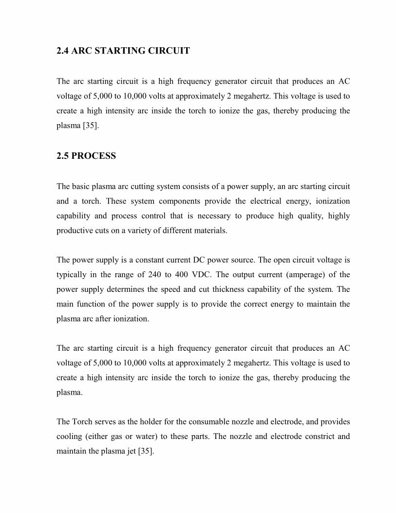
ELECTRODE. The purpose of the electrode is to provide a path for the electricity
from the power source and generate the cutting arc. The electrode is typically made
of copper with an insert made of hafnium. The Hafnium alloyed electrodes have good
wear life when clean, dry compressed air or nitrogen is used (although, electrode
consumption may be greater with air plasma than with nitrogen).
Fig 2.7 Electrode
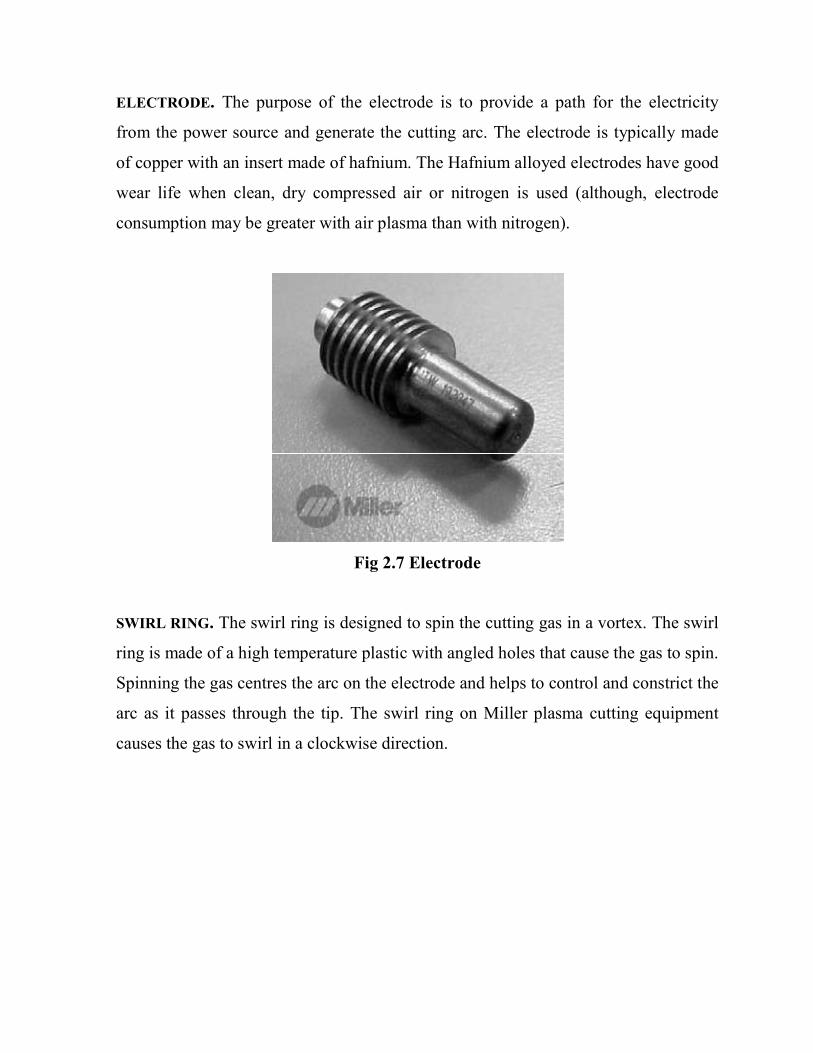
SWIRL RING. The swirl ring is designed to spin the cutting gas in a vortex. The swirl
ring is made of a high temperature plastic with angled holes that cause the gas to spin.
Spinning the gas centres the arc on the electrode and helps to control and constrict the
arc as it passes through the tip. The swirl ring on Miller plasma cutting equipment
causes the gas to swirl in a clockwise direction.

Fig. 2.8 Swirl Ring
TIP. The purpose of the torch tip is to constrict and focus the plasma arc. Constricting the arc increases the energy density and velocity. The tips are made of copper, with a specifically sized hole or orifice in the centre of the tip. Tips are sized according to the amperage rating of the torch that they are to be used in [19].
Fig. 2.9 Tip

2.6 TAGUCHI DESIGN OVERVIEW
Dr. Genichi Taguchi is regarded as the foremost proponent of robust parameter
design, which is an engineering method for product or process design that focuses on
minimizing variation and/or sensitivity to noise. When used properly, Taguchi
designs provide a powerful and efficient method for designing products that operate
consistently and optimally over a variety of conditions.
In robust parameter design, the primary goal is to find factor settings that minimize
response variation, while adjusting (or keeping) the process on target. After we
determine which factors affect variation, we can try to find settings for controllable
factors that will either reduce the variation, make the product insensitive to changes
in uncontrollable (noise) factors, or both. A process designed with this goal will
produce more consistent output. A product designed with this goal will deliver more
consistent performance regardless of the environment in which it is used.
Engineering knowledge should guide the selection of factors and responses.
When interactions among control factors are likely or not well understood, we should
choose a design that is capable of estimating those interactions. Minitab can help us
to select a Taguchi design that does not confound interactions of interest with each
other or with main effects.
Noise factors for the outer array should also be carefully selected and may require
preliminary experimentation. The noise levels selected should reflect the range of
conditions under which the response variable should remain robust. Robust parameter
design uses Taguchi designs (orthogonal arrays), which allow us to analyze many
factors with few runs. Taguchi designs are balanced, that is, no factor is weighted
more or less in an experiment, thus allowing factors to be analyzed independently of
each other [18].
Minitab provides both static and dynamic response experiments.
• In a static response experiment, the quality characteristic of interest has a fixed
level.
• In a dynamic response experiment, the quality characteristic operates over a range
of values and the goal is to improve the relationship between an input signal and an
output response.
An example of a dynamic response experiment is an automotive acceleration
experiment where the input signal is the amount of pressure on the gas pedal and the
output response is vehicle speed. We can create a dynamic response experiment by
adding a signal factor to a design − see Creating a dynamic response experiment. The
goal of robust experimentation is to find an optimal combination of control factor
settings that achieve robustness against (insensitivity to) noise factors. Minitab
calculates response tables, linear model results, and generates main effects and
interaction plots for:
• signal-to-noise ratios (S/N ratios, which provide a measure of robustness) vs. the
control factors
• means (static design) or slopes (dynamic design) vs. the control factors
• standard deviations vs. the control factors
• natural log of the standard deviations vs. the control factors
Use the results and plots to determine what factors and interactions are important and
evaluate how they affect responses. To get a complete understanding of factor effects
it is advisable to evaluate S/N ratios, means (static design), slopes (dynamic design),
and standard deviations [18].
2.7 WHAT IS TAGUCHI DESIGN?
A Taguchi design, or an orthogonal array, is a method of designing experiments that
usually requires only a fraction of the full factorial combinations. An orthogonal
array means the design is balanced so that factor levels are weighted equally. Because
of this, each factor can be evaluated independently of all the other factors, so the
effect of one factor does not influence the estimation of another factor.
In robust parameter design, we first choose control factors and their levels and choose
an orthogonal array appropriate for these control factors. The control factors
comprise the inner array. At the same time, we determine a set of noise factors, along
with an experimental design for this set of factors. The noise factors comprise the
outer array.
The experiment is carried out by running the complete set of noise factor settings at
each combination of control factor settings (at each run). The response data from
each run of the noise factors in the outer array are usually aligned in a row, next to
the factors settings for that run of the control factors in the inner array
Each column in the orthogonal array represents a specific factor with two or more
levels. Each row represents a run; the cell values indicate the factor settings for the
run. By default, Minitab's orthogonal array designs use the integers 1, 2, 3... to
represent factor levels. If we enter factor levels, the integers 1, 2, 3, ..., will be the
coded levels for the design [18].

CHAPTER 3
PROJECT METHODOLOGY

3.1 SPECIMEN PREPARATION
16 test specimens having dimension 30mm x 30mm x 12 mm were prepared for the
experimental work. The material for test specimen was Stainless Steel ASTM A 240
TP 316 L. Here L stands for Low Carbon Content.
Fig. 3.1 Test Specimen
3.2 MATERIAL
Stainless Steel is essentially a low carbon steel which contains chromium at 10% or
more by weight. It is this addition of chromium that gives steel its unique stainless,
corrosion resisting properties. The chromium content allows the formation of a tough,
adherent, invisible, corrosion resisting chromium oxide film on the steel surface.
Generally pipe flanges are manufactured from the Stainless Steel of grade 316 L.
Here L stands for Low Carbon Content [37].

Table 3.1. Composition ranges for 316 grades of stainless steels.
Grade
C Mn Si P S Cr Mo Ni N
316 Min - - - 0 - 16.0 2.00 10.0 -
Max 0.08 2.0 0.75 0.045 0.03 18.0 3.00 14.0 0.10
316L Min - - - - - 16.0 2.00 10.0 -
Max 0.03 2.0 0.75 0.045 0.03 18.0 3.00 14.0 0.10
316H Min 0.04 0.04 0 - - 16.0 2.00 10.0 -
max 0.10 0.10 0.75 0.045 0.03 18.0 3.00 14.0 -
Table 3.2 Mechanical properties of 316 grade stainless steels
Grade Tensile
Strength
(MPa)
Yield Str
0.2% Proof
(MPa)
Elongation
(% in
50mm)
Rockwell B
(HR B) max Brinell (HB)
max
316 515 205 40 95 217
316L 485 170 40 95 217
316H 515 205 40 95 217
Good oxidation resistance in intermittent service to 870°C and in continuous service
to 925°C. Continuous use of 316 in the 425-860°C range is not recommended if
subsequent aqueous corrosion resistance is important. Grade 316L is more resistant to
carbide precipitation and can be used in the above temperature range. Grade 316H
has higher strength at elevated temperatures and is sometimes used for structural and
pressure-containing applications at temperatures above about 500°C.

3.3EQUIPMENTS
Equipment for the experiment use is:
1. Plasma arc cutting system Silverin Make with Sharpline Bombay make
Burny 10 LCD
2. Digital weight balancer equipment
3. The surface roughness tester (FORM TALY SURF) Taylor Hobson Make
(U.K.)
3.3.1 Plasma Arc Cutting System
Plasma Arc Cutter used in this work is Silverin Make with Sharpline Bombay make
Burny 10 LCD. Before cutting, worker always know plasma arc cuts all electrically
conductive metals (Ox fuel is usually limited to steel), plasma arc cutting requires no
preheating, turnaround time is fast, the process produces a small heat-affected zone.
Table 3.3 Technical Features
Technical Features Machine
Supply voltage 3x400V - 50Hz
Rated power 30 kW
Operating pressure 5 bar
Primary fuse 16 A
Open circuit voltage 260 V
Pilot arc current 50 A

3.3.2 Digital Weight Balancer
The weight of the work pieces (specimens) before and after the cutting process need
to be measuredin order to obtain the amount of Material Removal Rate (MRR).
3.3.3 Surface Roughness Tester
There are five steps to measure the surface roughness of specimens. Firstly, clamp the
work piece of project use a clamping in the machine. And then, setting a prop of axis
likes up and down, right or left direction. After finish setting, can start measured a
work piece. Lastly, a data value for roughness can print out after finish measured.
The surface roughness tester (FORM TALY SURF) used in this work, with the
following specifications:
Manufacturer: Taylor Hobson, U.K,
Travelling length: 01mm-50mm,
Force: 4mN,
Stylus: Diamond 2µm tip radius,
Resolution: 16nm/1.0mm,
Software: Form ultra software
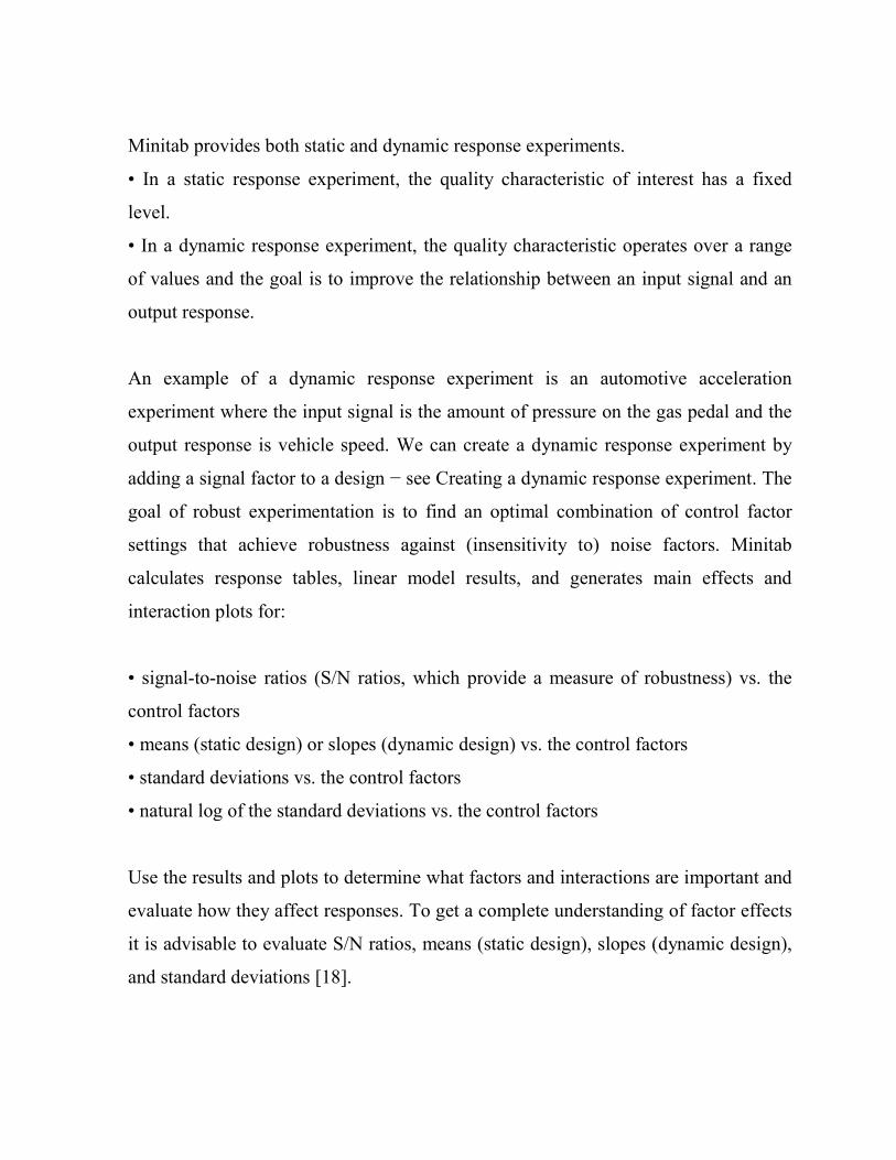
3.3.4 Power Supply
The power supply required depends on the material thickness and cutting speeds
desired. Increasing the power increases the cutting speed or enables thicker metals to
be cut without slow down. Power ratings are commonly between 20 and 200 kW.
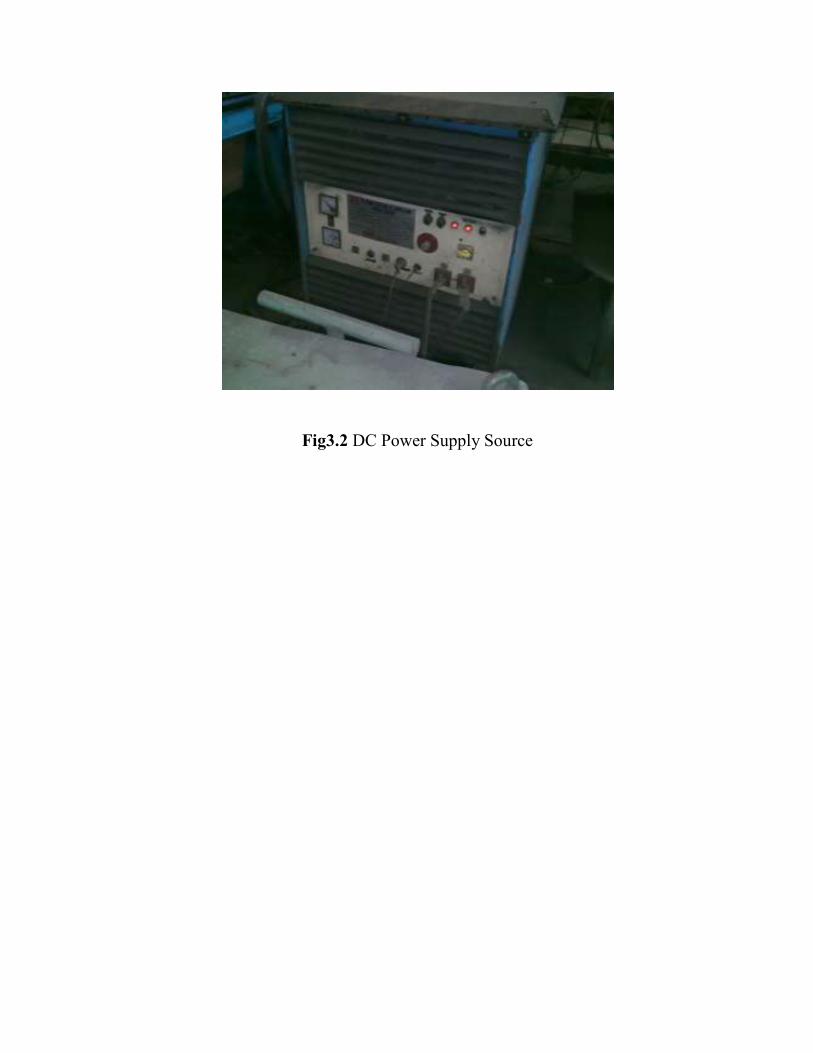
Fig3.2 DC Power Supply Source

3.4 DESIGN FACTORS
Design of Experiments technique has been utilized to obtain the best combination of
design factors to achieve optimum performance measures. Plasma Arc Cutting
involves several input parameters to be considered during machining process. In this
thesis, the combination factors such as Gas Pressure [bar], Current Flow Rate [A],
Cutting Speed [mm/min] and Arc Gap [mm] are considered. These factors are the
most important to have the best value for Material Removal Rate (MRR) and Surface
Roughness (Ra) when cutting material like Stainless Steel or Nickel Base Alloy etc.
Gas Pressure
According to Larry Jeffus, “Principle and Application of Welding” Sixth Addition,
almost any gas or gas mixture can be used today for the PAC process. Normally
Nitrogen or Argon with 0-35% Hydrogen is used for cutting Stainless Steel material.
We used Argon with 0-35% Hydrogen for our experiment purpose. It is important to
have the correct gas flow rate for the size tip, metal type and thickness. Too low a gas
flow will result in a cut having excessive dross and sharply bevelled sides. Too high a
gas flow will produce a poor cut because of turbulence in the plasma stream and
waste gas. Controlling the pressure is one way of controlling gas flow [23].
Current Flow Rate
Current flow rate is the value of current given during cutting process. The cause of
the burn-through was the increase in the cutting current or the decrease in the cutting
speed. When the cutting current increases or the cutting speed decreases, the stable
state of the keyhole changes accordingly. If the cutting current and the flow rate of

the plasma gas are increased and/or the cutting speed is decreased, the process will
withstand larger variations in the cutting parameters .
Cutting Speed
The best way to judge cutting speed is to look at the arc as it exits the bottom of the
work piece. Observe the angle of the cutting arc through the proper welding lens. If
cutting with air, the arc should be vertical straight down, or zero degrees as it exits
the bottom side of the cut. If cutting with nitrogen or argon/hydrogen, then the correct
cutting speed will produce a trailing arc (that is, an exit arc that is opposite to the
direction of torch travel).
The torch speed needs to be adjusted to get a good-quality cut. A cutting speed that is
too slow or too fast will cause cut quality problems. In most metals there is a window
between these two extremes that will give straight, clean, dross free cuts.
Arc Gap
Arc gap is the gap between the plasma arc cutter torch and welding electrodes
with the work piece [23] .
3.5 PLASMA ARC CUTTING RESPONSE
There are two Plasma Arc Cutting responses measured in this study, known as:
i. Material Removal Rate (MRR)
ii. Surface Roughness (Ra)

3.5.1 MATERIAL REMOVAL RATE
The material removal rate, MRR, can be defined as the volume of material removed
divided by the machining time. Material Removal Rate (MRR) is defined by:
MRR = WRW/T [g/min]
Where,
WRW: workpiece removal weight (g)
T: cutting time(s)
WRW is the weight different between before and after work piece cutting. The
volume different can be calculated when information regarding material density
available. The relation between WRW and WRV is given as follow:
WRV = WRW/ρ
Where,
ρ : Work piece density (g/ mm3)
The density of the Nickel-Base Alloys is 8 g/cm3 or 0.008g/mm3.
3.5.2 SURFACE ROUGHNESS
Roughness is a measure of the texture of a surface. It is quantified by the vertical
deviations of a real surface from its ideal form. If these deviations are large, the
surface is rough, if they are small the surface is smooth. Roughness is typically
considered to be the high frequency, short wavelength component of a measured
surface. Surface roughness normally measured.

Roughness plays an important role in determining how a real object will interact with
its environment. Rough surfaces usually wear more quickly and have higher friction
coefficients than smooth surfaces (see tribology). Roughness is often a good predictor
of the performance of a mechanical component, since irregularities in the surface may
form nucleation sites for cracks or corrosion.
In this thesis, the average surface roughness is measured and calculated. The average
surface roughness is the integral of the absolute value of the roughness profile height
over the evaluation length and is denoted by the following equation.
Where L is the length taken for observation, and Y is the ordinate of the profile curve
[9].

CHAPTER 4
DESIGN OF STUDY

4.1 OUTLINE OF THESIS WORK
It is found already many work has been done in MRR and Surface finish but very
little work has been done on optimization of Plasma Arc Cutting. Here in my thesis
work I will try to find out optimal value of MRR and SURFACE ROUGHNESS
(Ra).
For this I consult to Fabrication Division of BHEL, Bhopal, they suggested that
Stainless Steel (316L) materials are cheaply available and widely used in Plasma
Cutting Machine .Taguchi method using design of experiments approach can be used
to optimize a process Here we will to apply D.O.E approach for modelling of MRR
in PAC process and the various input parameters will be taken under experimental
investigation and then model will be prepared then again experimentation work will
be performed. The results obtain will be analyzed and the models will be produced by
using MINITAB software. This will help in improving the effective and efficient
working of the PAC process.
Various Input parameters
� Voltage
� Current Flow Rate
� Arc Gap
� Kerf (width of cut)
� Cutting Speed
� Material Type and Thickness
� Cutting gas Pressure
After extensive brain storming with the experts of Fabrication Division of BHEL
Bhopal, it has been found that above are important input parameters for studying
material remove rate. As I am going to perform my work on Silverin make Plasma

Arc Cutting Machine No. B/0/2163 and after literature review four main input
parameters selected are Gas Pressure, Current, Cutting Speed, and Arc Gap.
The other two parameters kerf (5mm) and Material Thickness (12mm) is kept
fixed for the whole experiment. The material used is Stainless Steel ASTM
A240TP316L in the overall experiment.
4.2 DESIGN OF EXPERIMENT
The objective of this research work is to study MRR and Surface roughness, the
design variables can be summarized as follows:
a) Two levels of the Gas Pressure (6Bar and 7Bar).
b) Two levels of Current Flow Rate (150A and 200A).
c) Two levels of Cutting Speed (400mm/min and 600mm/min).
d) Two levels of Arc Gap (2mm and 4mm)
For conducting the experiments, it has been decided to follow the Taguchi method of
experimental design and an appropriate orthogonal array is to be selected after taking
into consideration the above design variables. Out of the above listed design
variables, the orthogonal array was to be selected for four design variables (namely
Gas Pressure, Current, Cutting Speed and Arc gap) which would constitute the L16
orthogonal array.
The two most important outputs are Material Removal Rate and Surface Roughness
the same have been selected as response parameters for this research work also. The
effect of the variation in input process parameter will be studied on these two
response parameters and the experimental data will be analyzed as per Taguchi
method to find out the optimum machining condition and percentage contribution of
each factor. The following machining parameters were kept fixed.
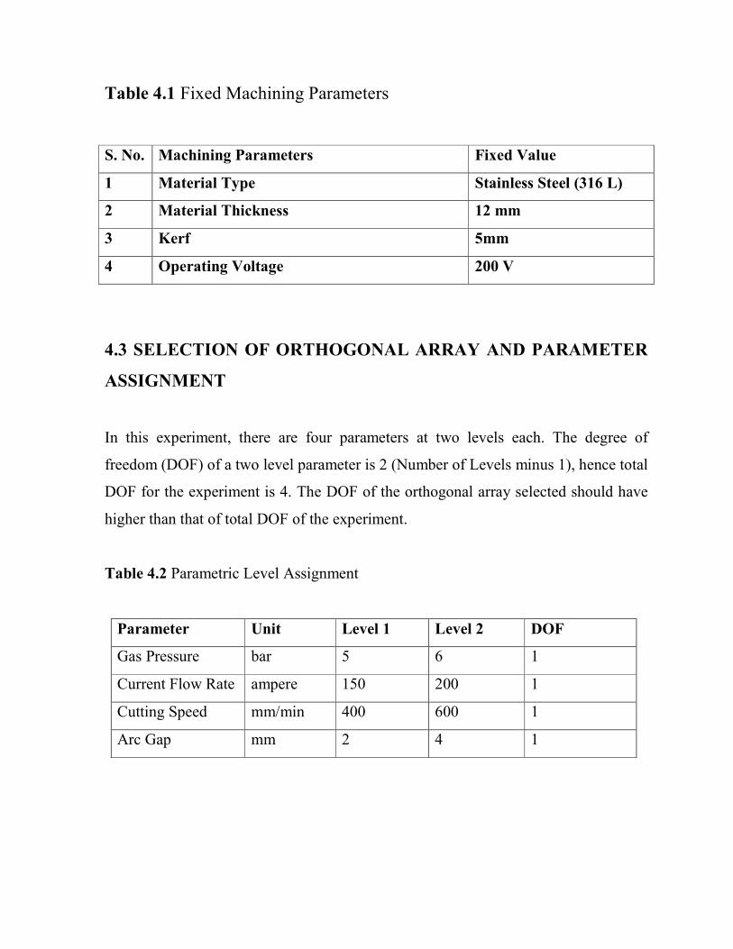
Table 4.1 Fixed Machining Parameters
S. No. Machining Parameters Fixed Value
1 Material Type Stainless Steel (316 L)
2 Material Thickness 12 mm
3 Kerf 5mm
4 Operating Voltage 200 V
4.3 SELECTION OF ORTHOGONAL ARRAY AND PARAMETER
ASSIGNMENT
In this experiment, there are four parameters at two levels each. The degree of
freedom (DOF) of a two level parameter is 2 (Number of Levels minus 1), hence total
DOF for the experiment is 4. The DOF of the orthogonal array selected should have
higher than that of total DOF of the experiment.
Table 4.2 Parametric Level Assignment
Parameter Unit Level 1 Level 2 DOF
Gas Pressure bar 5 6 1
Current Flow Rate ampere 150 200 1
Cutting Speed mm/min 400 600 1
Arc Gap mm 2 4 1

4.3.1 Standard L16 Array with (2*4) :- Column number 1 2 4 and 8 of
L16(2**15) Array is used for this experiment:-
Table 4.3 Experimental Layout in Coded Factor Levels
Runs Gas Pressure Current Cutting Speed Arc Gap
1 1 1 1 1
2 1 1 1 2
3 1 1 2 1
4 1 1 2 2
5 1 2 1 1
6 1 2 1 2
7 1 2 2 1
8 1 2 2 2
9 2 1 1 1
10 2 1 1 2
11 2 1 2 1
12 2 1 2 2
13 2 2 1 1
14 2 2 1 2
15 2 2 2 1
16 2 2 2 2
The above table displays the L16 (2*4) Taguchi design (orthogonal array). L16
means 16 runs. 2*4 means 4 factors with 2 levels each. This array is orthogonal;
factor levels are weighted equally across the entire design. The table columns
represent the control factors, the table rows represent the runs (combination of factor
levels), and each table cell represents the factor level for that run.

4.4 SIGNAL TO NOISE (S/N) RATIO
Noise factors are those that are either too hard or uneconomical to control even
though they may cause unwanted variation in performance. It is observed that on
target performance usually satisfies the user best, and the target lies under acceptable
range of product quality are often inadequate. If Y is the performance characteristic
measured on a continuous scale when ideal or target performance is T then according
to Taguchi the loss caused L(Y) can be modeled by a quadratic function as shown in
equation (1)
L(Y) = K (Y-T2)........................ (1)
The objective of robust design is specific; robust design seeks optimum settings of
parameters to achieve a particular target performance value under the most noise
condition. Suppose that in a set of statistical experiment one finds a average quality
characteristic to be µ and standard deviation to be σ. Let desired performance be µ1
.Then one make adjustment in design to get performance on target by adjusting value
of control factor by multiplying it by the factor . Since on target is goal the
loss after adjustment is due to variability remaining from the new standard deviation.
Loss after adjustment shown in equation (2):
The factor reflects the ratio of average performance µ^2(which is the signal) and
σ^2(the variance of performance) the noise. Maximizing or S/N ratio therefore
become equivalent to minimizing the loss after adjustment. Finding a correct
objective function to maximize in an engineering design problem is very important.

Depending upon the type of response, the following three types of S/N ratios are
employed in practice:
Larger is Better
The signal-to-noise (S/N) ratio is calculated for each factor level combination. The
formula for the larger-is-better S/N ratio using base 10 log is:
S/N = -10*log(Sum of (1/Y2)/n)
Where
Y = responses for the given factor level combination and,
n = number of responses in the factor level combination.
Smaller is Better
The signal-to-noise (S/N) ratio is calculated for each factor level combination. The
formula for the smaller-is-better S/N ratio using base 10 log is:
S/N = -10*log(Sum of(Y2)/n)
Where Y = responses for the given factor level combination and
n = number of responses in the factor level combination.
� In my thesis work MRR is considered larger is better. Value of MRR is
measured by difference between initial and final weight after machining
� Surface roughness of specimen is considered as smaller is better. Surface
roughness is measured by Taylor Hobson Make Talysurf Instrument.

4.5 ANOVA (Analysis of Variance)
The purpose of the statistical analysis of variance (ANOVA) is to investigate which
design parameter significantly affects the material removal rate and surface
roughness. Based on the ANOVA, the relative importance of the machining
parameters with respect to material removal rate and surface roughness is
investigated to determine more accurately the optimum combination of the machining
parameters.
Two types of variations are present in experimental data:
1. Within treatment variability
2. Observation to observation variability
So ANOVA helps us to compare variabilities within experimental data. In my thesis
ANOVA table is made with help of MINITAB 15 software. When performance
varies one determines theaverage loss by statistically averaging the quadratic loss.
The average loss is proportional to the mean squared error of Y about its target T.
The initial techniques of the analysis of variance were developed by the statistician
and geneticist R. A. Fisher in the 1920s and 1930s, and are sometimes known as
Fisher's ANOVA or Fisher's analysis of variance, due to the use of Fisher's F-
distribution as part of the test of statistical significance.
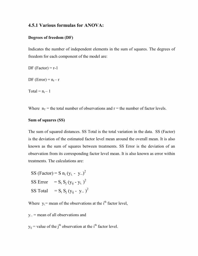
4.5.1 Various formulas for ANOVA:
Degrees of freedom (DF)
Indicates the number of independent elements in the sum of squares. The degrees of
freedom for each component of the model are:
DF (Factor) = r-1
DF (Error) = nt – r
Total = nt – 1
Where nT = the total number of observations and r = the number of factor levels.
Sum of squares (SS)
The sum of squared distances. SS Total is the total variation in the data. SS (Factor)
is the deviation of the estimated factor level mean around the overall mean. It is also
known as the sum of squares between treatments. SS Error is the deviation of an
observation from its corresponding factor level mean. It is also known as error within
treatments. The calculations are:
SS (Factor) = S ni (yi. - y..)2
SS Error = Si Sj (yij - yi. )2
SS Total = Si Sj (yij - y.. )2
Where yi.= mean of the observations at the ith factor level,
y.. = mean of all observations and
yij = value of the jth observation at the ith factor level.
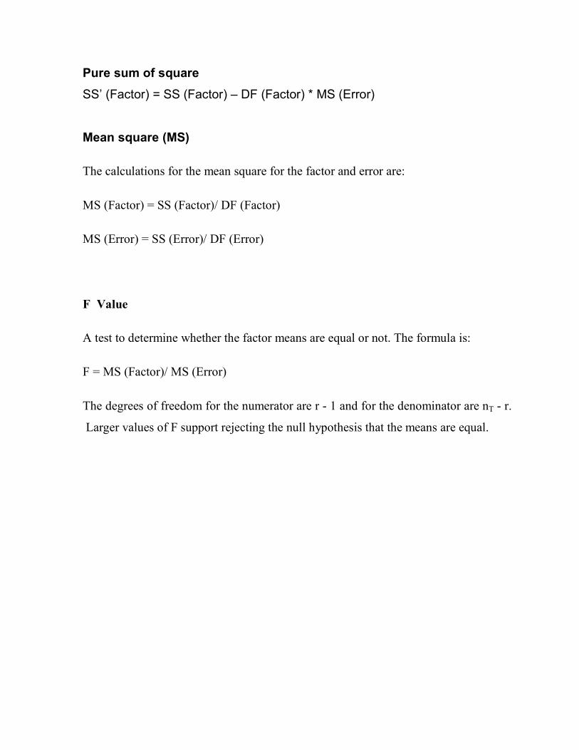
Pure sum of square
SS’ (Factor) = SS (Factor) – DF (Factor) * MS (Error)
Mean square (MS)
The calculations for the mean square for the factor and error are:
MS (Factor) = SS (Factor)/ DF (Factor)
MS (Error) = SS (Error)/ DF (Error)
F Value
A test to determine whether the factor means are equal or not. The formula is:
F = MS (Factor)/ MS (Error)
The degrees of freedom for the numerator are r - 1 and for the denominator are nT - r.
Larger values of F support rejecting the null hypothesis that the means are equal.

CHAPTER-5
EXPERIMENTAL ANALYSIS

5.1 EXPERIMENTAL LAYOUT
Since in my thesis work there are four factors and two levels for each which are
shown below:
Table 5.1 Values of variables at different level
Control Factors Unit Level 1 Level 2 DOF
Gas Pressure bar 5 6 1
Current Flow Rate ampere 150 200 1
Cutting Speed mm/min 400 600 1
Arc Gap mm 2 4 1
After deciding parameters and levels as shown above orthogonal array L16 decided
as per degree of freedom of each factor and dof of interaction among the parameters.
Data of parameter was collected in such a way that it shouldn’t damage or cause any
accident to operator and as per literature review. Now perform experiment as per
orthogonal array (L16) on Plasma Arc Cutting Machine Number B/0/2163, output
like MRR and surface roughness is being given in tabulated form. After the
experimental results have been obtained, analysis of the results was carried out
analytically as well as graphically. Graphical analysis is done by MINITAB, shows
interactions of all parameters. Then ANOVA of the experimental data has been done
to calculate the contribution of each factor in each response. Then we calculated S/N
ratio for MRR and surface roughness of specimens.
Then we obtain optimal conditions has been calculated for MRR and surface
roughness of specimen. The following table shows readings of MRR and surface
roughness at each experiment, it also shows S/N ratio for MRR and surface
roughness at each experiments.
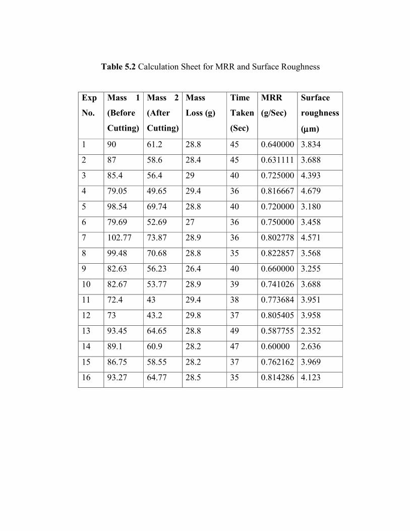
Table 5.2 Calculation Sheet for MRR and Surface Roughness
Exp
No.
Mass 1
(Before
Cutting)
Mass 2
(After
Cutting)
Mass
Loss (g)
Time
Taken
(Sec)
MRR
(g/Sec)
Surface
roughness
(µµµµm)
1 90 61.2 28.8 45 0.640000 3.834
2 87 58.6 28.4 45 0.631111 3.688
3 85.4 56.4 29 40 0.725000 4.393
4 79.05 49.65 29.4 36 0.816667 4.679
5 98.54 69.74 28.8 40 0.720000 3.180
6 79.69 52.69 27 36 0.750000 3.458
7 102.77 73.87 28.9 36 0.802778 4.571
8 99.48 70.68 28.8 35 0.822857 3.568
9 82.63 56.23 26.4 40 0.660000 3.255
10 82.67 53.77 28.9 39 0.741026 3.688
11 72.4 43 29.4 38 0.773684 3.951
12 73 43.2 29.8 37 0.805405 3.958
13 93.45 64.65 28.8 49 0.587755 2.352
14 89.1 60.9 28.2 47 0.60000 2.636
15 86.75 58.55 28.2 37 0.762162 3.969
16 93.27 64.77 28.5 35 0.814286 4.123
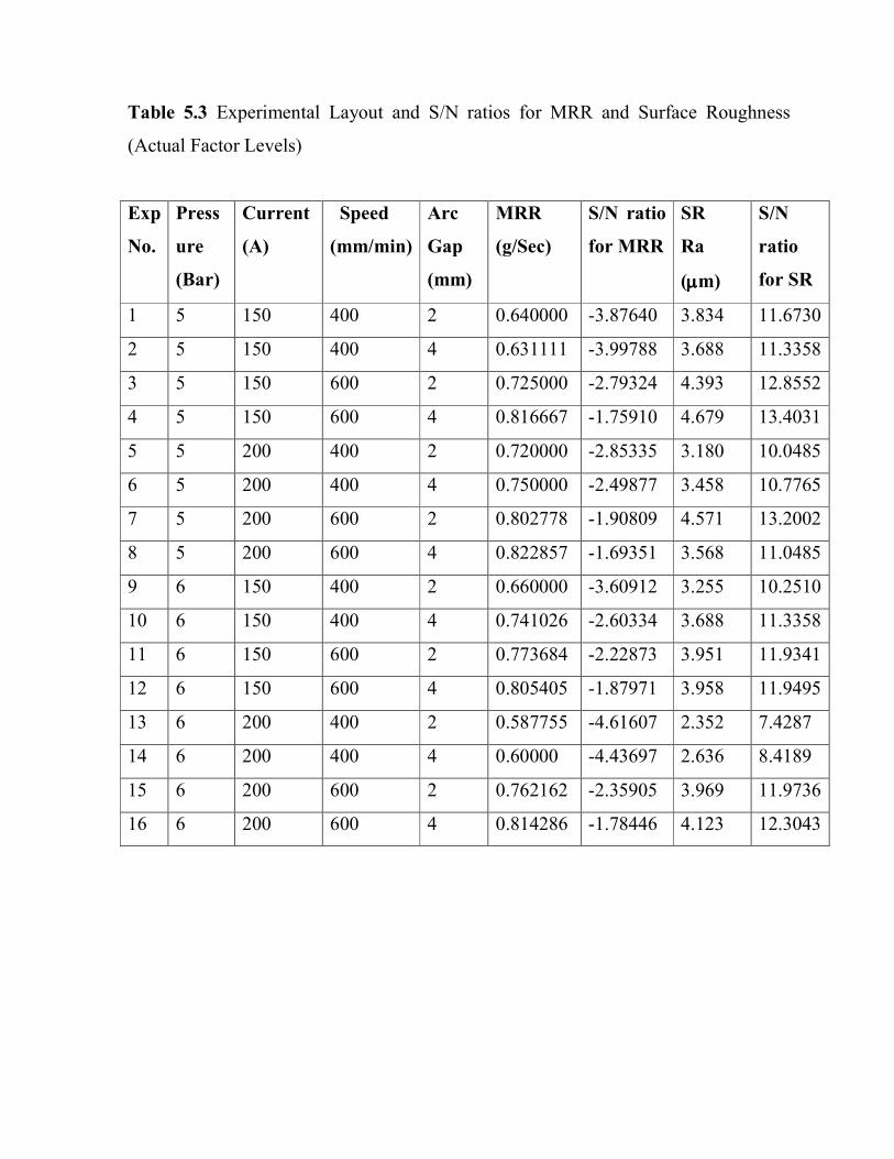
Table 5.3 Experimental Layout and S/N ratios for MRR and Surface Roughness
(Actual Factor Levels)
Exp
No.
Press
ure
(Bar)
Current
(A)
Speed
(mm/min)
Arc
Gap
(mm)
MRR
(g/Sec)
S/N ratio
for MRR
SR
Ra
(µµµµm)
S/N
ratio
for SR
1 5 150 400 2 0.640000 -3.87640 3.834 11.6730
2 5 150 400 4 0.631111 -3.99788 3.688 11.3358
3 5 150 600 2 0.725000 -2.79324 4.393 12.8552
4 5 150 600 4 0.816667 -1.75910 4.679 13.4031
5 5 200 400 2 0.720000 -2.85335 3.180 10.0485
6 5 200 400 4 0.750000 -2.49877 3.458 10.7765
7 5 200 600 2 0.802778 -1.90809 4.571 13.2002
8 5 200 600 4 0.822857 -1.69351 3.568 11.0485
9 6 150 400 2 0.660000 -3.60912 3.255 10.2510
10 6 150 400 4 0.741026 -2.60334 3.688 11.3358
11 6 150 600 2 0.773684 -2.22873 3.951 11.9341
12 6 150 600 4 0.805405 -1.87971 3.958 11.9495
13 6 200 400 2 0.587755 -4.61607 2.352 7.4287
14 6 200 400 4 0.60000 -4.43697 2.636 8.4189
15 6 200 600 2 0.762162 -2.35905 3.969 11.9736
16 6 200 600 4 0.814286 -1.78446 4.123 12.3043

5.2 EXPERIMENTAL RESULTS FOR MRR
65
-2.0
-2.4
-2.8
-3.2
-3.6
150100
600400
-2.0
-2.4
-2.8
-3.2
-3.6
42
pressure
Mean of SN ratios
current
cutting speed arc gap
Main Effects Plot for SN ratiosData Means
Signal-to-noise: Larger is better
Graph 5.1 Effects of various factors on S/N Ratio of MRR
By using MINITAB software we obtain some interactions if we look at the graph we
will observe that with increase in Gas Pressure MRR S/N ratio is decreasing. Material
removal rate increases with increase in Current, Cutting Speed and Arc gap.

Main Effect Plot for Mean of MRR
65
0.80
0.75
0.70
0.65
150100
600400
0.80
0.75
0.70
0.65
42
Gas Pressure
Mean of Means
current
cutting speed arc gap
Main Effects Plot for MeansData Means
Graph 5.2 Effects of various factors on Mean of MRR
With the above graph of mean of MRR and various factors, we can observe that
MRR is decreasing with increase in Gas Pressure and MRR is increasing with
increase in Current, Cutting Speed and Arc Gap.
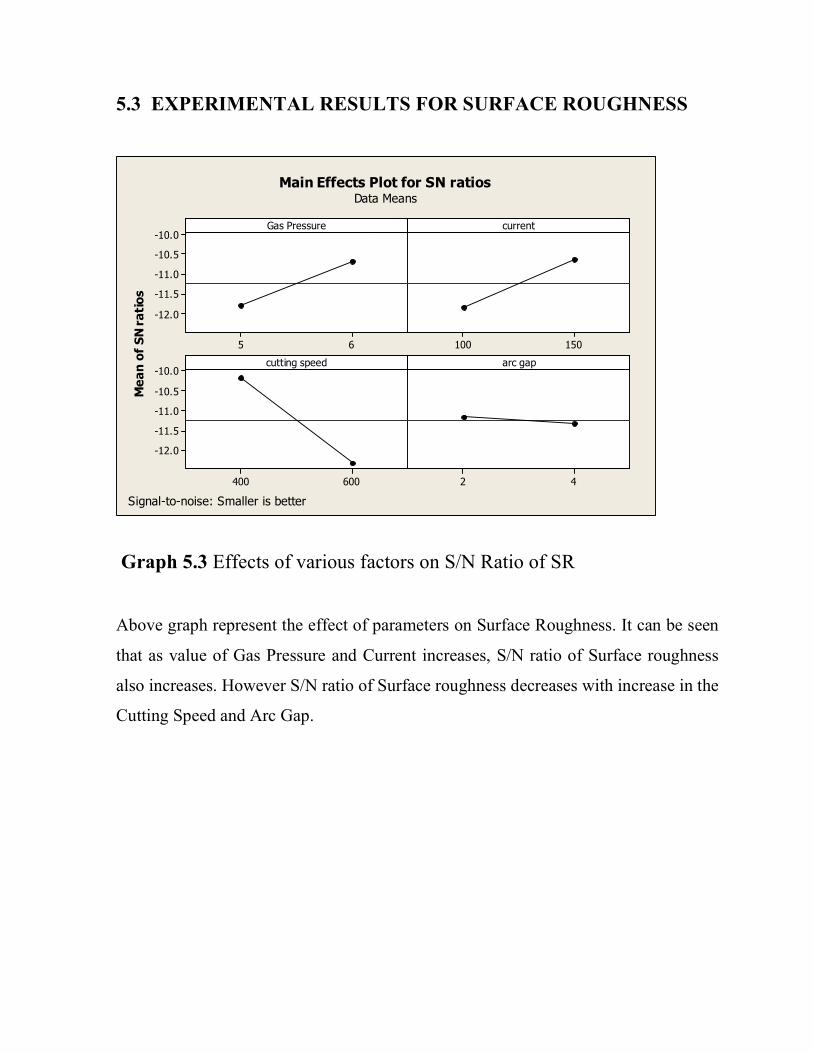
5.3 EXPERIMENTAL RESULTS FOR SURFACE ROUGHNESS
65
-10.0
-10.5
-11.0
-11.5
-12.0
150100
600400
-10.0
-10.5
-11.0
-11.5
-12.0
42
Gas Pressure
Mean of SN ratios
current
cutting speed arc gap
Main Effects Plot for SN ratiosData Means
Signal-to-noise: Smaller is better
Graph 5.3 Effects of various factors on S/N Ratio of SR
Above graph represent the effect of parameters on Surface Roughness. It can be seen
that as value of Gas Pressure and Current increases, S/N ratio of Surface roughness
also increases. However S/N ratio of Surface roughness decreases with increase in the
Cutting Speed and Arc Gap.
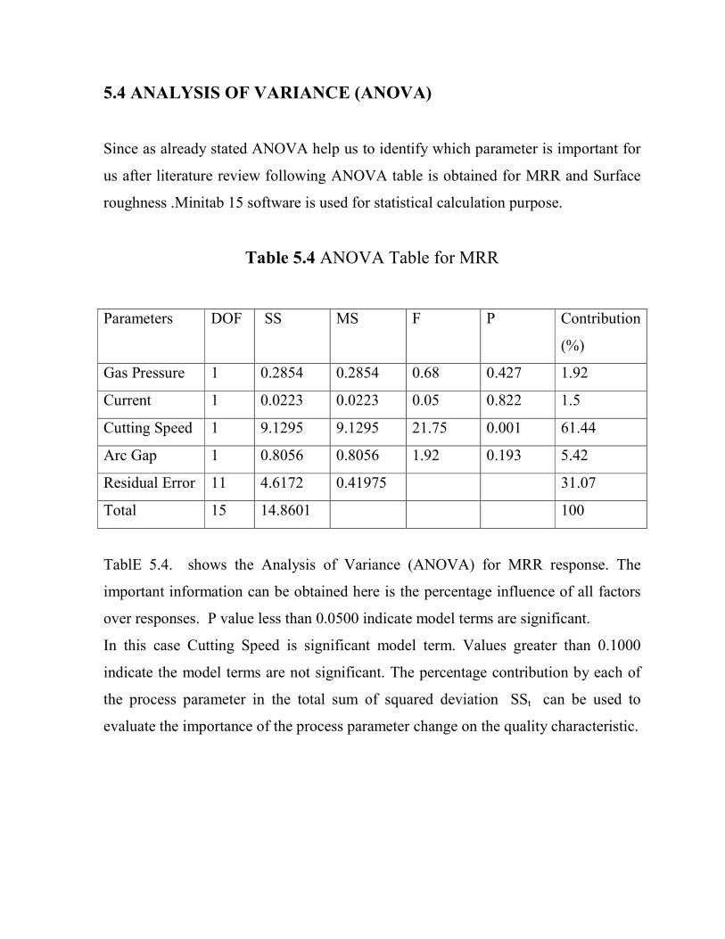
5.4 ANALYSIS OF VARIANCE (ANOVA)
Since as already stated ANOVA help us to identify which parameter is important for
us after literature review following ANOVA table is obtained for MRR and Surface
roughness .Minitab 15 software is used for statistical calculation purpose.
Table 5.4 ANOVA Table for MRR
Parameters DOF SS MS F P Contribution
(%)
Gas Pressure 1 0.2854 0.2854 0.68 0.427 1.92
Current 1 0.0223 0.0223 0.05 0.822 1.5
Cutting Speed 1 9.1295 9.1295 21.75 0.001 61.44
Arc Gap 1 0.8056 0.8056 1.92 0.193 5.42
Residual Error 11 4.6172 0.41975 31.07
Total 15 14.8601 100
TablE 5.4. shows the Analysis of Variance (ANOVA) for MRR response. The
important information can be obtained here is the percentage influence of all factors
over responses. P value less than 0.0500 indicate model terms are significant.
In this case Cutting Speed is significant model term. Values greater than 0.1000
indicate the model terms are not significant. The percentage contribution by each of
the process parameter in the total sum of squared deviation SSt can be used to
evaluate the importance of the process parameter change on the quality characteristic.

Table 5.5 ANOVA Table for Surface Roughness (Ra)
Parameters DOF SS MS F P Contribution
(%)
Gas Pressure 1 4.7795 4.7795 5.45 0.040 12.22
Current 1 5.6862 5.6862 6.48 0.027 14.53
Cutting Speed 1 18.9228 18.9228 21.58 0.001 48.36
Arc Gap 1 0.0912 0.0912 0.10 0.753 0.23
Residual Error 11 9.6452 0.8768 24.65
Total 15 39.1250 100
From table 5.5 we can conclude that Gas Pressure, Current and Cutting Speed are
significant terms because their P values are less than 0.05. P values greater than 0.01
indicates that model terms are not significant. The P value for the factor Arc Gap is
0.753 which is not significant. There is 75.3% chance that a this large could occur
due to noise. The percentage contribution by each of the process parameter in the
total sum of squared deviation SSt can be used to evaluate the importance of the
process parameter change on the quality characteristic.

5.5 CONFIRMATION TEST
From S/N ratio and mean of each level of every factor we will construct response
table for MRR and Surface Roughness which are given below:
Table 5.6 Response table for S/N ratio of MRR
Level Gas Pressure Current Cutting Speed Arc Gap
1 -2.673 -2.843 -3.561 -3.031
2 -2.940 -2.769 -2.051 -2.582
Effect (∆) 0.267 0.075 1.511 0.449
Rank 3 4 1 2
From above response table and main effect plot of MRR we can conclude that the
optimum condition for MRR is, A1B2 C2 D2 i. e.
Gas Pressure: 5 Bar
Current: 150 A
Cutting Speed: 600 mm/min
Arc Gap: 4mm
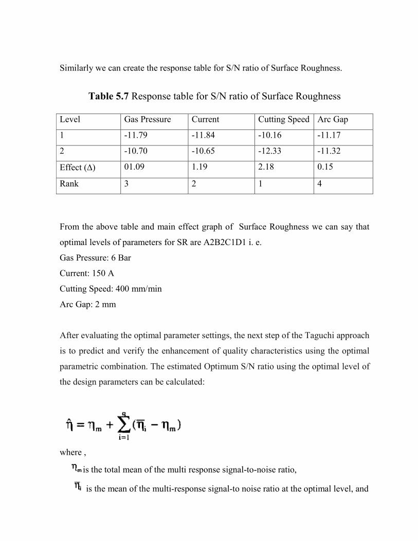
Similarly we can create the response table for S/N ratio of Surface Roughness.
Table 5.7 Response table for S/N ratio of Surface Roughness Level Gas Pressure Current Cutting Speed Arc Gap
1 -11.79 -11.84 -10.16 -11.17
2 -10.70 -10.65 -12.33 -11.32
Effect (∆) 01.09 1.19 2.18 0.15
Rank 3 2 1 4
From the above table and main effect graph of Surface Roughness we can say that
optimal levels of parameters for SR are A2B2C1D1 i. e.
Gas Pressure: 6 Bar
Current: 150 A
Cutting Speed: 400 mm/min
Arc Gap: 2 mm
After evaluating the optimal parameter settings, the next step of the Taguchi approach
is to predict and verify the enhancement of quality characteristics using the optimal
parametric combination. The estimated Optimum S/N ratio using the optimal level of
the design parameters can be calculated:
where ,
is the total mean of the multi response signal-to-noise ratio,
is the mean of the multi-response signal-to noise ratio at the optimal level, and

q is the number of the process parameters that significantly affect the multiple
quality characteristics.
Based on the above equation the estimated multi response signal to noise ratio can be
obtained.
5.5.1Prediction of Optimum Value of MRR:
Here = -2.80625
Optimum S/N Ratio for MRR = -2.80625 + (-2.673 + 2.80625) + (-2.769 + 2.80625)
+
(- 2.051 + 2.80625) + (-2.582 + 2.80625)
= - 1.6525
And the corresponding value of MRR = Yopt2 = = 0.6829202
Predicted Optimum Value of MRR, Yopt = 0.8264 g/sec

5.5.2Prediction of Optimum Value of SR :
Here = - 11.245
Optimum S/N Ratio for SR = -11.245 + (-10.70 + 11.245) + (-10.65 + 11.245) +
(- 10.16 + 11.245) + (-11.17 + 11.245)
= - 8.945
And the corresponding value of SR = Yopt2 = = 7.8433
Predicted Optimum Value of SR Yopt = 2.8006 µµµµm
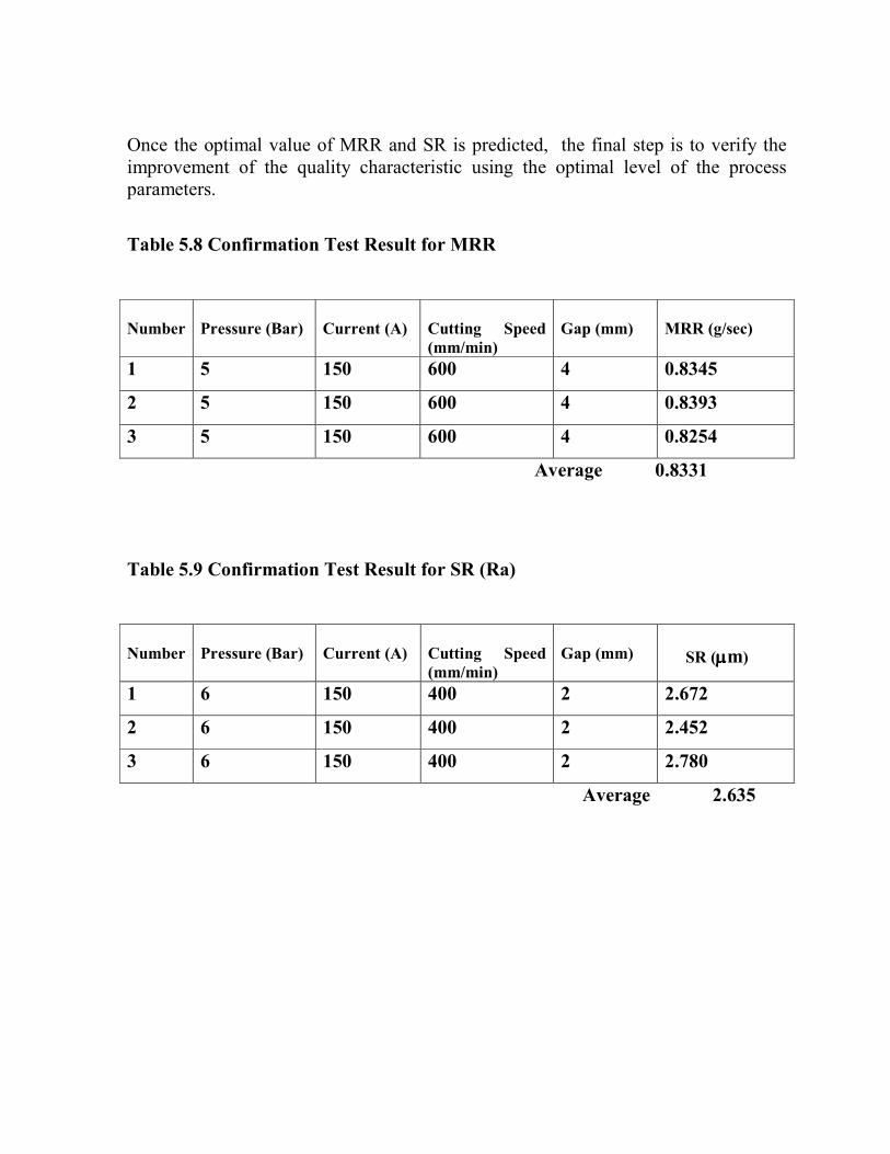
Once the optimal value of MRR and SR is predicted, the final step is to verify the improvement of the quality characteristic using the optimal level of the process parameters.
Table 5.8 Confirmation Test Result for MRR
Number
Pressure (Bar)
Current (A)
Cutting Speed
(mm/min)
Gap (mm)
MRR (g/sec)
1 5 150 600 4 0.8345
2 5 150 600 4 0.8393
3 5 150 600 4 0.8254
Average 0.8331
Table 5.9 Confirmation Test Result for SR (Ra)
Number
Pressure (Bar)
Current (A)
Cutting Speed
(mm/min)
Gap (mm)
SR (µµµµm)
1 6 150 400 2 2.672
2 6 150 400 2 2.452
3 6 150 400 2 2.780
Average 2.635

After performing experiment as per given optimum levels for MRR and SR following
results obtained:
Table 5.10 Summary Table for Results
MRR (g/sec) Optimum value of
A1B2C2D2 = 0.8264
Experimental result of
A1B2C2D2= 0.8331
Percentage
= 0.81%
Surface
Roughness (µm)
Optimum value of
A2B2C1D1 = 2.8006
Experimental result of
A2B2C1D1= 2.635
Percentage
= 5.91%
So we can say that there is 0.81% improvement in MRR and also Surface Roughness
reduce with 5.91%. This finding indicated that the experiments in this study possess
excellent repetitiveness and great potential for future reference.
CHAPTER-6
MATHEMATICAL MODELLING

6.1 INTRODUCTION TO REGRESSION ANALYSIS
The term multiple regression literally means stepping back toward the average. It was
use by British mathematician Sir Francis Galton .Regression analysis is a
mathematical measure of the average relationship between two or more variables in
terms of the original units of the data. In regression analysis there are two types of
variables. The value whose value is influenced or is to be predicted is called
dependent variable and the variable which influences the values or is to be used for
prediction is called independent variable. Regression analysis can be done in two
ways;
� Bivariate regression
� Multiple regression
6.1.1 Bivariate Regression:
Two variables X and Y may be related to each other or inexactly. In physical
sciences, variables frequently have an exact relationship to each other. The simplest
relationship can be expressed by
Y=a+bX
Where the values of the coefficient, a and b, determine respectively the precise height
and steepness of the line. Thus coefficient a represent to as the intercept or constant,
and coefficient b referred to as the slope.
In contrast, relationship between variables in social sciences is almost always inexact.
The equation for a linear relationship between two social science variables would be
written as:
Y=a+bX+e
Where e represents the presence of error
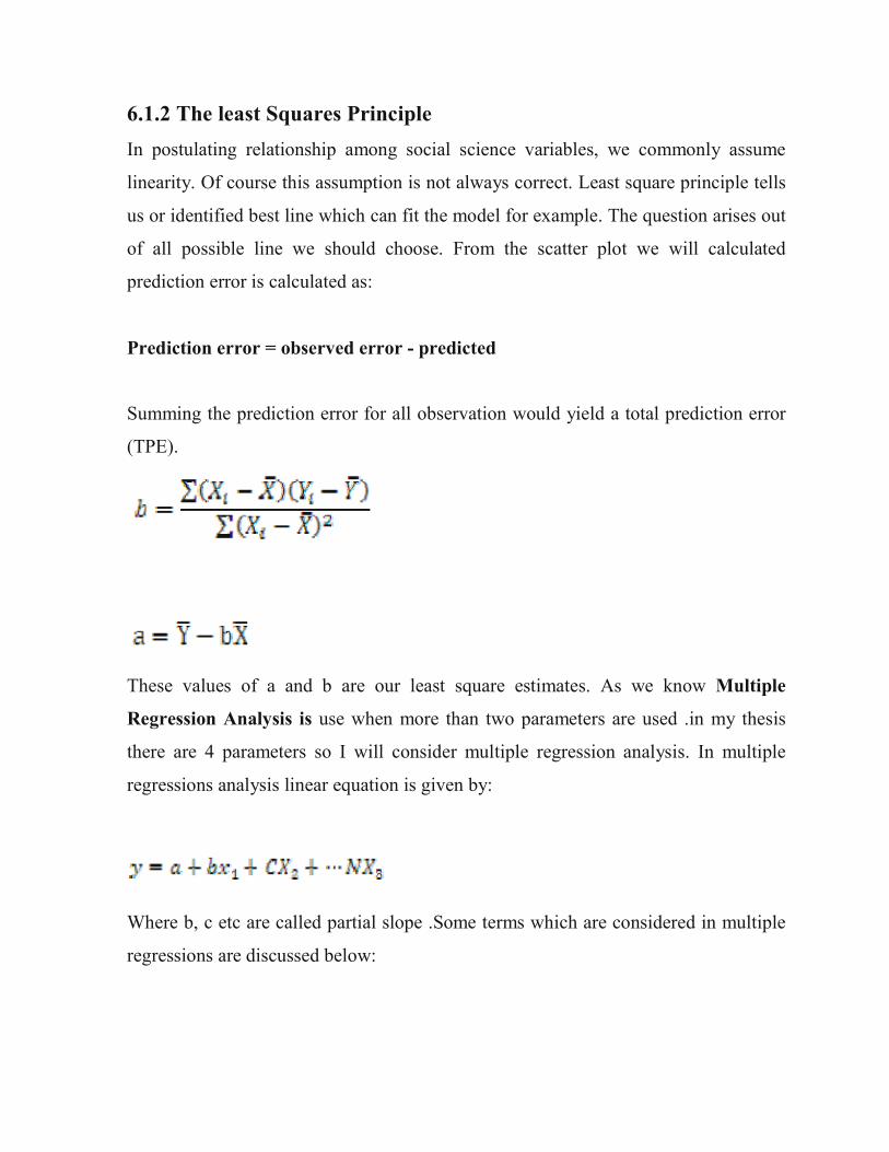
6.1.2 The least Squares Principle
In postulating relationship among social science variables, we commonly assume
linearity. Of course this assumption is not always correct. Least square principle tells
us or identified best line which can fit the model for example. The question arises out
of all possible line we should choose. From the scatter plot we will calculated
prediction error is calculated as:
Prediction error = observed error - predicted
Summing the prediction error for all observation would yield a total prediction error
(TPE).
These values of a and b are our least square estimates. As we know Multiple
Regression Analysis is use when more than two parameters are used .in my thesis
there are 4 parameters so I will consider multiple regression analysis. In multiple
regressions analysis linear equation is given by:
Where b, c etc are called partial slope .Some terms which are considered in multiple
regressions are discussed below:

6.1.3 Residual
The difference between an observed value (y) and its corresponding fitted value (ŷ) is
called residual. Residual values are especially useful in regression and ANOVA
procedures because they indicate the extent to which a model accounts for the
variation in the observed data.
6.1.4 Sampling Error
When estimating a population parameter from a sample it is important not only to
derive a specific value but also estimate the effect of the sampling error on the
estimate. To accomplish this it is necessary to consider the concept of a sampling
distribution for a regression coefficient.
This could be easily understood as the distribution of estimates of the regression
coefficient that would be result if sample of given size were drawn repeatedly from
the population and coefficient calculated from each sample .Because coefficient
estimated from random samples will deviate from populations values by varying
amounts, the estimates , the estimates of the coefficient from a series of random
samples of population will not be identical but instead will distribute themselves
around a mean . the estimated standard deviation of the sampling distribution of a
regression coefficients is known as a standard error and is denoted by ‘s’.

6.1.5 Coefficient of Determination R2
This is called coefficient of determination indicates explanatory power of any
regression model. Its value lies between +1 and 0. It can also been shown that R –sq
is the correlation between actual and predicted value. It will reach maximum value
when dependent variable is perfectly predicted by regression equation.
6.1.6 Multicollinearity
Multicollinearity means that none of that independent variable or linear variable is
perfectly correlated with another independent variable or linear combination of other
independent variable .In multiple regression if there is collinearity among variables ,
then regression surface not even define (because in multiple regression instead of two
plane we will consider multiple plain) as there are infinite number of surface that fit
the observation equally well and there fore it is impossible to drive unique estimates
of the intercepts and partial slope coefficient for the regression
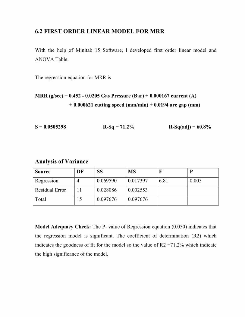
6.2 FIRST ORDER LINEAR MODEL FOR MRR
With the help of Minitab 15 Software, I developed first order linear model and
ANOVA Table.
The regression equation for MRR is
MRR (g/sec) = 0.452 - 0.0205 Gas Pressure (Bar) + 0.000167 current (A)
+ 0.000621 cutting speed (mm/min) + 0.0194 arc gap (mm)
S = 0.0505298 R-Sq = 71.2% R-Sq(adj) = 60.8%
Analysis of Variance
Source DF SS MS F P
Regression 4 0.069590 0.017397 6.81 0.005
Residual Error 11 0.028086 0.002553
Total 15 0.097676 0.097676
Model Adequacy Check: The P- value of Regression equation (0.050) indicates that
the regression model is significant. The coefficient of determination (R2) which
indicates the goodness of fit for the model so the value of R2 =71.2% which indicate
the high significance of the model.
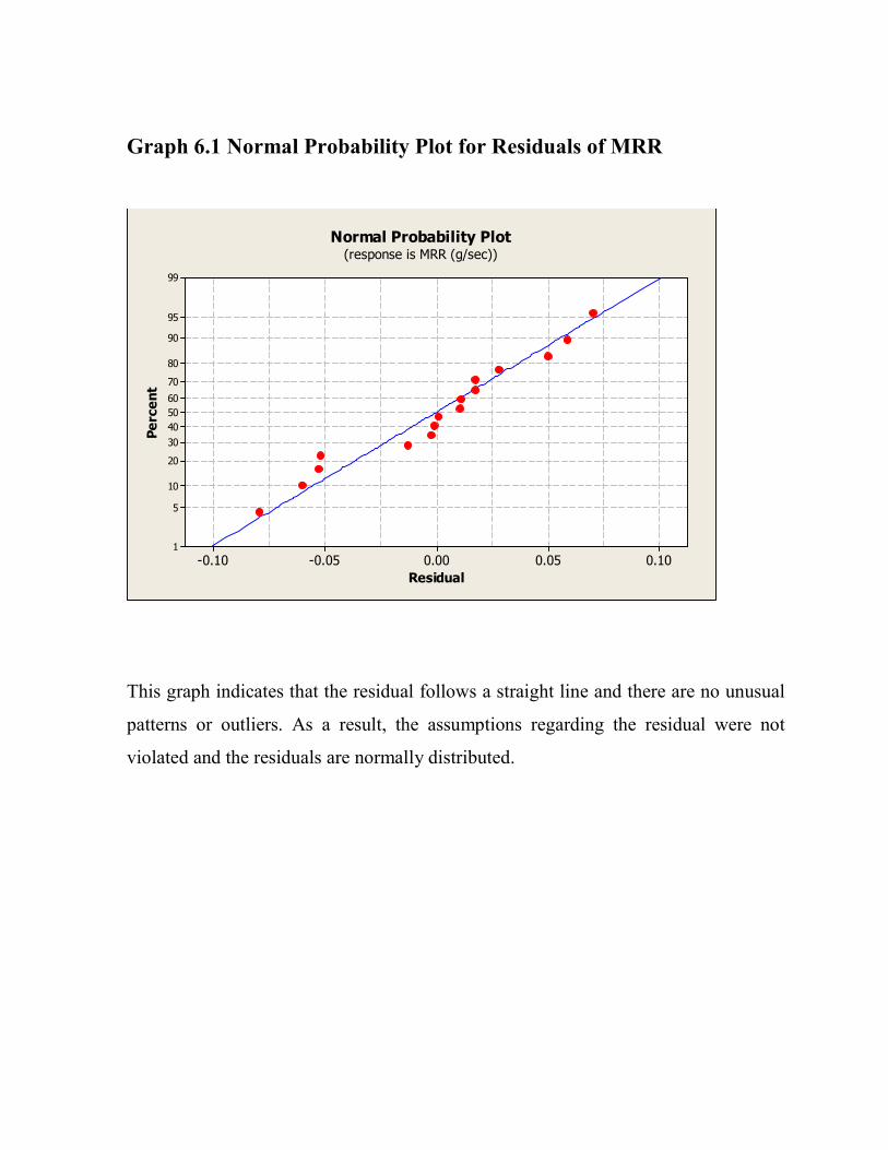
Graph 6.1 Normal Probability Plot for Residuals of MRR
0.100.050.00-0.05-0.10
99
95
90
80
70
60
50
40
30
20
10
5
1
Residual
Percent
Normal Probability Plot(response is MRR (g/sec))
This graph indicates that the residual follows a straight line and there are no unusual
patterns or outliers. As a result, the assumptions regarding the residual were not
violated and the residuals are normally distributed.

6.3 FIRST ORDER LINEAR MODEL FOR SURFACE
ROUGHNESS
The regression equation for SR (Ra) is:
SR (Ra) = 4.91 - 0.430 Gas Pressure (Bar) - 0.00897 current (A)
+ 0.00445 cutting speed (mm/min) + 0.0183 arc gap (mm)
S = 0.352974 R-Sq = 77.5% R-Sq(adj) = 69.3%
Analysis of Variance
Source DF SS MS F P
Regression 4 4.7189 1.1797 9.47 0.001
Residual Error 11 1.3705 0.1246
Total 15 6.0894
Model Adequacy Check: The P- value of Regression equation (0.001) indicates that
the regression model is significant. The coefficient of determination (R2) which
indicates the goodness of fit for the model so the value of R2 =77.5% which indicate
the high significance of the model.

Graph 6.2Normal Probability Plot for Residuals of Surface Roughness
(Ra)
0.80.60.40.20.0-0.2-0.4-0.6-0.8
99
95
90
80
70
60
50
40
30
20
10
5
1
Residual
Percent
Normal Probability Plot(response is SR (micro m))
This graph indicates that the residual follows a straight line and there are no unusual
patterns or outliers. As a result, the assumptions regarding the residual were not
violated and the residuals are normally distributed.

CHAPTER 7
RESULT, CONCLUSION AND FUTURE SCOPE

7.1 SUMMARY
Objective of this study is to find out optimal condition of Plasma Arc Cutting
Machine for maximizing MRR and minimizing Surface Roughness (Ra). For this 16
specimens of Stainless Steel material were prepared which were easily and cheaply
available in the scrap yard of Fabrication Division of BHEL, Bhopal. The mechanical
properties of Stainless Steel (316L) are given in appendix B .Machining process is
carried out on Plasma Arc Cutting Machine number B/0/2163 which is available in
the Fabrication Division of BHEL, Bhopal. I considered MRR and Surface
Roughness (Ra) as two most important outputs.
As per literature review Gas Pressure, Current Flow Rate, Cutting Speed and Arc Gap
were considered as most important parameters. In order to perform minimum
experiments Taguchi method has been employed. For this L16 orthogonal array is
considered .Experiment results and various response graph for MRR and SR (Ra)
were obtained and there optimum value were also considered.
In chapter 6 mathematical modeling were done .For this I consider regression
analysis . Mathematical equation both for MRR and SR (Ra)were obtained by
regression analysis.
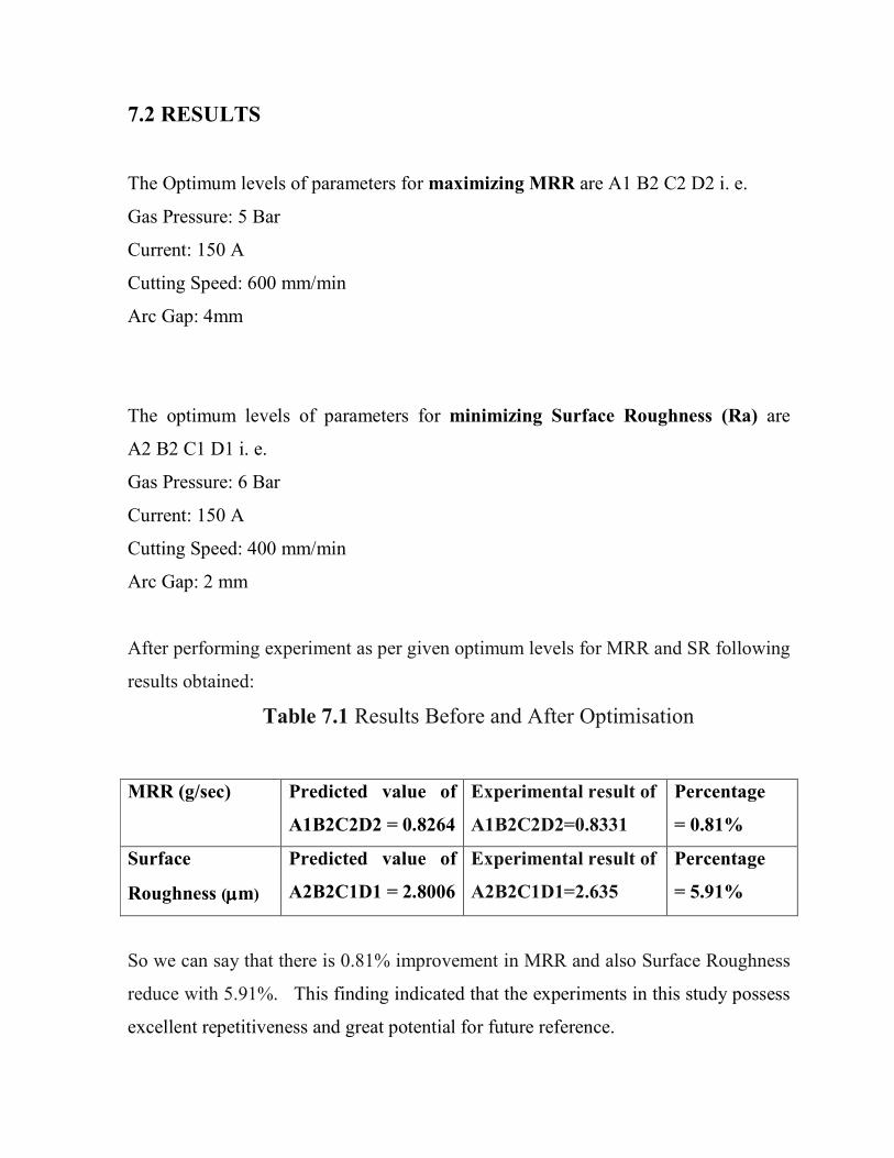
7.2 RESULTS
The Optimum levels of parameters for maximizing MRR are A1 B2 C2 D2 i. e.
Gas Pressure: 5 Bar
Current: 150 A
Cutting Speed: 600 mm/min
Arc Gap: 4mm
The optimum levels of parameters for minimizing Surface Roughness (Ra) are
A2 B2 C1 D1 i. e.
Gas Pressure: 6 Bar
Current: 150 A
Cutting Speed: 400 mm/min
Arc Gap: 2 mm
After performing experiment as per given optimum levels for MRR and SR following
results obtained:
Table 7.1 Results Before and After Optimisation
MRR (g/sec) Predicted value of
A1B2C2D2 = 0.8264
Experimental result of
A1B2C2D2=0.8331
Percentage
= 0.81%
Surface
Roughness (µµµµm)
Predicted value of
A2B2C1D1 = 2.8006
Experimental result of
A2B2C1D1=2.635
Percentage
= 5.91%
So we can say that there is 0.81% improvement in MRR and also Surface Roughness
reduce with 5.91%. This finding indicated that the experiments in this study possess
excellent repetitiveness and great potential for future reference.
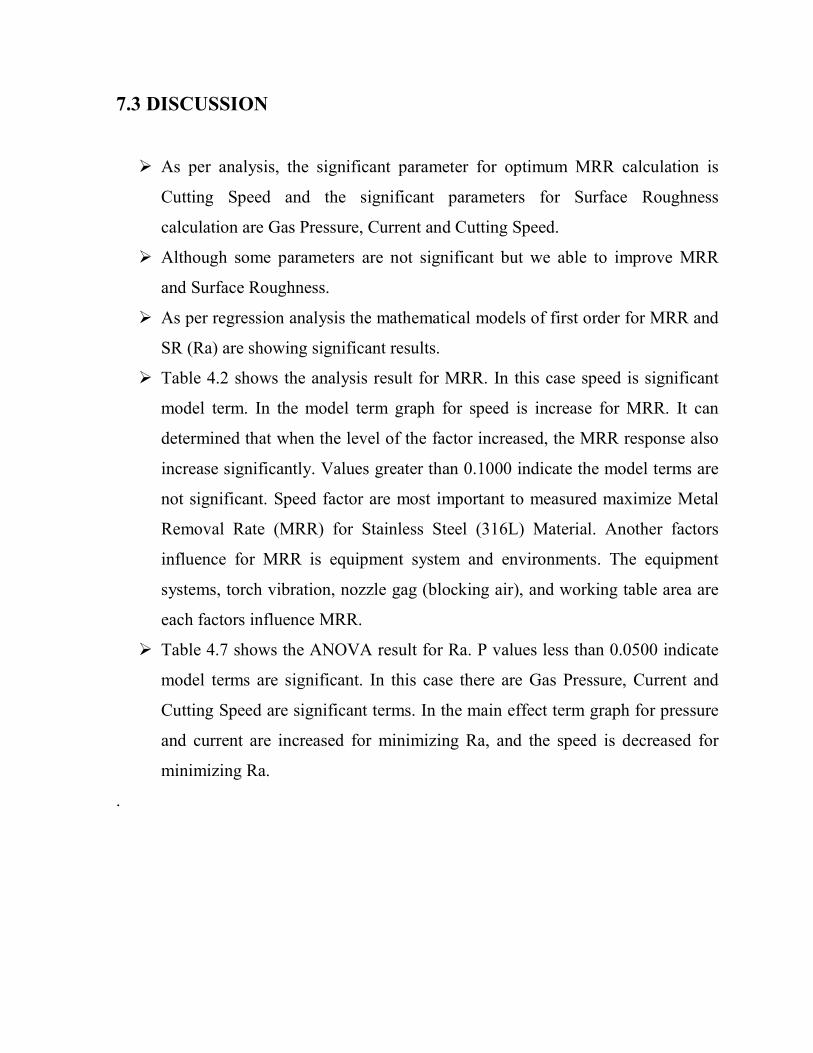
7.3 DISCUSSION
� As per analysis, the significant parameter for optimum MRR calculation is
Cutting Speed and the significant parameters for Surface Roughness
calculation are Gas Pressure, Current and Cutting Speed.
� Although some parameters are not significant but we able to improve MRR
and Surface Roughness.
� As per regression analysis the mathematical models of first order for MRR and
SR (Ra) are showing significant results.
� Table 4.2 shows the analysis result for MRR. In this case speed is significant
model term. In the model term graph for speed is increase for MRR. It can
determined that when the level of the factor increased, the MRR response also
increase significantly. Values greater than 0.1000 indicate the model terms are
not significant. Speed factor are most important to measured maximize Metal
Removal Rate (MRR) for Stainless Steel (316L) Material. Another factors
influence for MRR is equipment system and environments. The equipment
systems, torch vibration, nozzle gag (blocking air), and working table area are
each factors influence MRR.
� Table 4.7 shows the ANOVA result for Ra. P values less than 0.0500 indicate
model terms are significant. In this case there are Gas Pressure, Current and
Cutting Speed are significant terms. In the main effect term graph for pressure
and current are increased for minimizing Ra, and the speed is decreased for
minimizing Ra.
.

7.4 CONCLUSION
This thesis has presented an application of the Taguchi method to the optimization of
the machining parameters of Plasma Arc Cutting Machine. As shown in this study,
the Taguchi method provides a systematic and efficient methodology for determining
optimal parameters with far less work than would be required for most optimization
techniques. The confirmation experiments were conducted to verify the optimal
parameters. It has been shown that Material Removal Rate (MRR) and Surface
Roughness (Ra) can be significantly improved in the Plasma Arc Cutting process
using the optimum level of parameters.
Plasma Arc Cutting Machine is widely utilized in BHEL, Bhopal to cut materials
such as Stainless Steel and Nickel-Base Alloys. This is the basis work where Plasma
Arc Cutting was utilized to perform the material removal process at finishing stage.
The Plasma Arc Cutting (PAC) machining of Stainless Steel (316L) has been
performed with the application of combination with design of experiment (DOE).The
PAC parameters studied were how to have setting for the parameter such as Gas
Pressure, Current flow, Cutting Speed and Arc gap of machine.
From ANOVA of MRR we can say that some parameters are not making any
significant effect .This is because we must take large number of observations either
by considering L27 0r L32 orthogonal array with 3 level designs.
Mathematical equation for MRR of first order is of R-sq of 71.2% and for Surface
Roughness (Ra) is of R-sq 77.5% which is acceptable.

7.5 SCOPE OF FUTURE WORK
Based on result and discussion summary, this project had archive it main objective
but an improvement still can done to improve more on the Metal Removal Rate
(MRR) and Surface Roughness (Ra) of parts by features. Some of the suggestions to
improve the result include the replication of the model which can reduce the
variations of the data and increase the reliability of the data.
Based on this work many improvements can be made and the scope can also be
widened. Following are suggestion for future work:
� Using Plasma Arc Cutting system, add the parameter such as Kerf, Voltage,
angle, material dimension, and change advance material such as brass and
bronze then compare the result obtained.
� Using other methodology in the same material of study to compare the results
obtained such as Response Surface Methodology, Grey Relational Analysis,
and Genetic Algorithm etc.
� Study for manual calculation for other method in DOE to improve knowledge
and skills.
� No interaction is considered so we can consider interaction by applying L27
or L32 with 3-level design this will improve optimum condition as compare to
L16 considered in this work.
� Also side clearance and thermal effect on material and work piece like Heat
Affected Zone (HAZ) can also be considered to study the effect on properties
of work piece.

BIBLIOGRAPHY
Journals Referred
1. Joseph C. Chen, Ye Li (2009) Taguchi Based Six Sigma Approach to Optimize
Plasma Arc Cutting Process: an Industrial Case Study. International Journal of
Advanced Manufacturing Technology 41: 760-769.
2. Asiabanpour Bahram (2009) Optimising the automated plasma cutting process
by design of experiments. Int. J. Rapid Manufacturing, Vol. 1, No. 1, 2009.
3. Mahapatra S S, Patnaik Amar (2006) Optimization of wire electrical discharge
machining (WEDM) process parameters using Taguchi method. International
Journal of Advanced Manufacturing Technology.
4. Hatala Michal Faculty of Manufacturing Technologies of the Technical
University of Košice Štúrova The Principle of Plasma Cutting Technology
and Six Fold Plasma Cutting. 5th International Multidisciplinary Conference.
5. Mahapatra S S (2007) An evolutionary approach to parameter optimisation of
submerged arc welding in the hard facing process 462 Int. J. Manufacturing
Research, Vol. 2, No. 4, 2007 .
6. Uttarwar S S, Chopade I K, Effect Of Voltage Variation On MRR For
Stainless Steel EN Series 58A (AISI 302B) In Electrochemical Machining: A
Practical Approach. 2OHProceedings of the World Congress on Engineering
2009 Vol II WCE 2009, July 1 - 3, 2009, London, U.K.
7. Hussain Altaf (2010) Surface Roughness Analysis in Machining of GFRP
Composites by Carbide Tool (K20). European Journal of Scientific Research

ISSN 1450-216X Vol.41 No.1 (2010), pp.84-98.
8. Lajis Mohammd Amri (2009) The Implementation of Taguchi Method on
EDM Process of Tungsten Carbide. European Journal of Scientific Research
ISSN 1450-216X Vol.26 No.4 (2009), pp.609-617.
9. Kandananond Karin (2009) Characterization of FDB Sleeve Surface
Roughness Using the Taguchi Approach. European Journal of Scientific
Research ISSN 1450-216X Vol.33 No.2 (2009), pp.330-337
10. Abdul Kadir Gullu, Umut Atici (2006) Investigation of the Effects of Plasma
Arc Parameters on the Structure Variation of AISI 304 and St 52 Steels.
International Journal of Material and Design 27: 1157-1162
11. ASTM Standard Designation: A 240/A 240M-09a. Standard Specification for
Chromium and Chromium-Nickel Stainless Steel Plate, Sheet, and Strip for
Pressure Vessels and for General Application.
12. Tarng Y S, Yang W. H. (1998) Application of the Taguchi Method to the
Optimization of the Submerged Arc Welding Process. Journal of Material and
Manufacturing Processes, 13:3,455-467
13. Uey-Jiuh Tzou, Ding Yeng Chen (2006). “ Application of Taguchi Method in
the Optimization of Cutting Parameters for Turning Operation” Lunghwa
niversity of Science and Technology, Taiwan (R. O. C.)
14. Martikainen, J.K.,and Moisio,T.J.I.(1993).Invetigation of the effect of welding
parameters on weld quality of plasma arc keyhole welding of structural

steels,Welding Journal 72(7): 329-340
15. Lin, J.L. and Lin, C.L. (2001). The Use of the Orthogonal Array with Grey
Relational Analysis to Optimize the Electrical Discharge Machining Process
with Multiple Performance Characteristics, Journal of Machine Tools
Manufacture.
Books Referred
16. Roy, R.K. (2001).Design of Experiment Canada: John Wiley & Sons,Inc.
17. Parweld Plasma Process Synopsis September 2001 Release
18. Design of Experiment Manual. Minitab 15 Statistical Software.
19. Plasma Arc Cutting Theory, Miller Electric Mfg. Co. Publication.
20. Ross J. Philip (2008) Taguchi Techniques for Quality Engineering 4th Edition
Tata Mcgraw Hill Publication.
21. Montgomery C. Douglas (2007) Design and Analysis of Experiments 5th
Edition: John Wiley & Sons, Inc; p. 76-86
22. Kalpakjian, S & R Schmid, S.(2000).Manufacturing Engineering and
Technology:4th Edition UK: Prentice-Hall, Inc; p. 164-165
23. Jeffus Larry (2003). Welding Principles and Applications: Sixth Edition: Inc;
p. 182-203.
Websites
24. Plasma Cutting, http://en.wikipedia.org/wiki/Plasma_cutting
25. PlasmaEquipment,http://www.answers.com/topic/plasma-torch?cattechnology
26. Benefits Of Plasma Arc Cutting, http://www.airgas.com
27. http://www.aws.org/wj/2003/02/024/#A,
28. Plasma(Physics), http://en.wikipedia.org/wiki/Plasma_(physics)#History
29. Plasma Cutting,
http://www.lincolnelectric.com/knowledge/articles/content/plasma.asp
30. Plasma Cutting, http://www.esab.com/global/en/education/processes-
plasmacutting.
31. Cutting Process, http://www.twi.co.uk/j32k/protected/band_3/jk51.html
32. Cutting Torch, http://www.welding-advisers.com/Cutting-torch.html
33. Quality,http://www.centricut.com/TA_CutQualityProblems.htm,4 April 2008
34. Technical System Consideration, http://tristate.apogee.net/et/eftcpat.asp
35. Plasma Cutting, http://www.hypertherm.com/technology.htm

36. Roughness,
http://en.wikipedia.org/wiki/Roughnesshttp://home.howstuffworks.com/plasma
-cutter1.htm
37. Stainless Steel Properties, http://www.fanagalo.co.za/tech/tech_grade_316.htm

MINITAB SOFTWARE ANALYSIS SHEETS