analysis of selected determinate structural...
TRANSCRIPT
Dr. Mohammed E. Haque, P.E.
Lecture Notes
COSC321Haque 1
PDF_B4 (Analysis of Selected Determinate Structural Systems)
Analysis of Selected Determinate Structural Systems • Planar Trusses – Method of Joints
• Planar Trusses – Method of Sections
• Pinned Frames with Multi-force Members
• Retaining Walls
Dr. Mohammed E. Haque, P.E.
Lecture Notes
COSC321Haque 2
PDF_B4 (Analysis of Selected Determinate Structural Systems)
Planar Trusses – Method of Joints
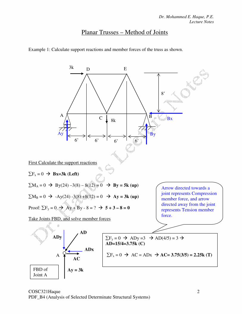
Example 1: Calculate support reactions and member forces of the truss as shown.
First Calculate the support reactions
∑Fx = 0 � Bx=3k (Left)
∑MA = 0 � By(24) –3(8) – 8(12) = 0 � By = 5k (up)
∑MB = 0 � -Ay(24) -3(8) +8(12) = 0 � Ay = 3k (up)
Proof: ∑Fy = 0 � Ay + By - 8 = ? � 5 + 3 – 8 = 0
Take Joints FBD, and solve member forces
Bx
8’
6’ 6’ 6’ 6’
8k
3k
A B C
D E
By Ay
A
Ay = 3k
AD
ADx
ADy ∑Fy = 0 � ADy =3 � AD(4/5) = 3 �
AD=15/4=3.75k (C)
∑Fx = 0 � AC = ADx � AC= 3.75(3/5) = 2.25k (T) AC
FBD of
Joint A
Arrow directed towards a
joint represents Compression
member force, and arrow
directed away from the joint
represents Tension member
force.
Dr. Mohammed E. Haque, P.E.
Lecture Notes
COSC321Haque 3
PDF_B4 (Analysis of Selected Determinate Structural Systems)
D
DC AD
=3.75
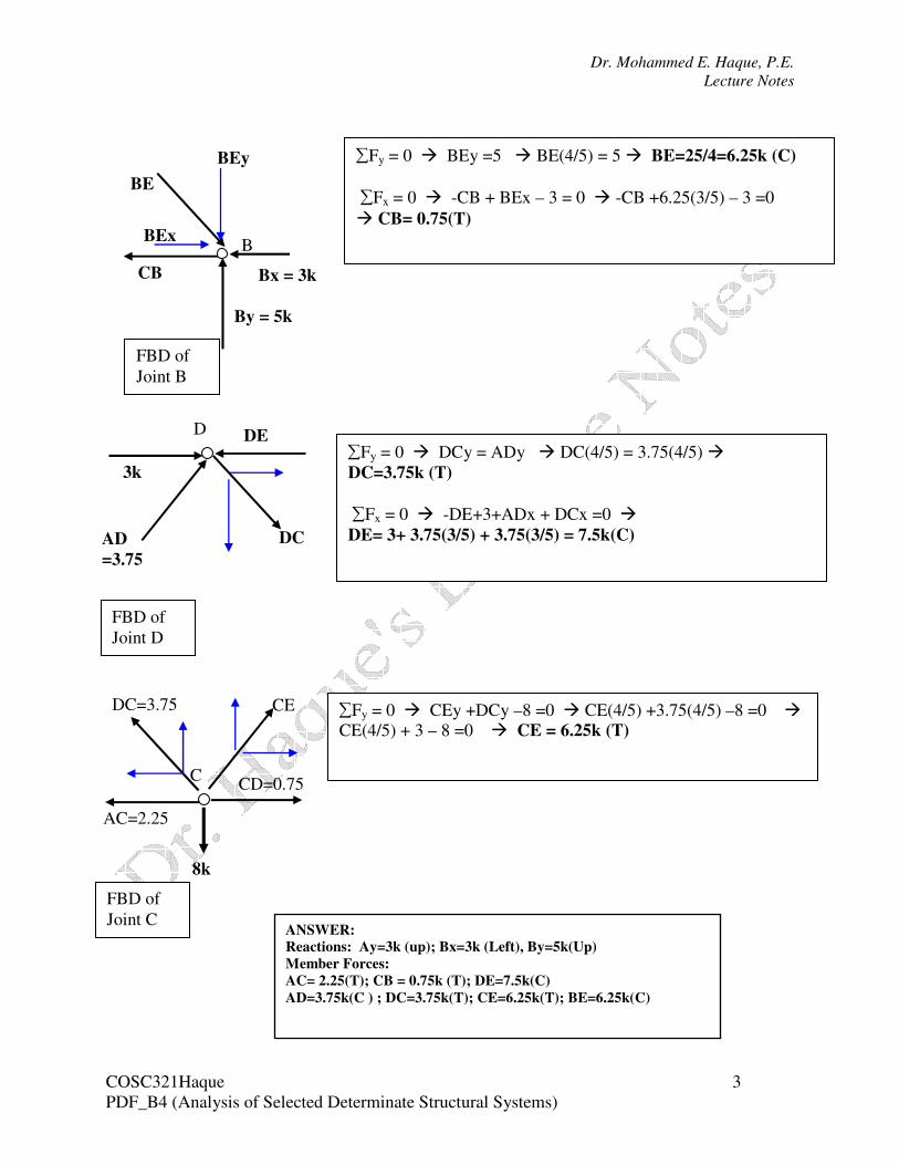
DE ∑Fy = 0 � DCy = ADy � DC(4/5) = 3.75(4/5) �
DC=3.75k (T)
∑Fx = 0 � -DE+3+ADx + DCx =0 �
DE= 3+ 3.75(3/5) + 3.75(3/5) = 7.5k(C)
3k
FBD of
Joint D
B
By = 5k
BE
BEx
BEy ∑Fy = 0 � BEy =5 � BE(4/5) = 5 � BE=25/4=6.25k (C)
∑Fx = 0 � -CB + BEx – 3 = 0 � -CB +6.25(3/5) – 3 =0
� CB= 0.75(T)
CB Bx = 3k
FBD of
Joint B
C
DC=3.75
8k
CD=0.75
∑Fy = 0 � CEy +DCy –8 =0 � CE(4/5) +3.75(4/5) –8 =0 �
CE(4/5) + 3 – 8 =0 � CE = 6.25k (T)
AC=2.25
FBD of
Joint C
CE
ANSWER:
Reactions: Ay=3k (up); Bx=3k (Left), By=5k(Up)
Member Forces:
AC= 2.25(T); CB = 0.75k (T); DE=7.5k(C)
AD=3.75k(C ) ; DC=3.75k(T); CE=6.25k(T); BE=6.25k(C)
Dr. Mohammed E. Haque, P.E.
Lecture Notes
COSC321Haque 4
PDF_B4 (Analysis of Selected Determinate Structural Systems)
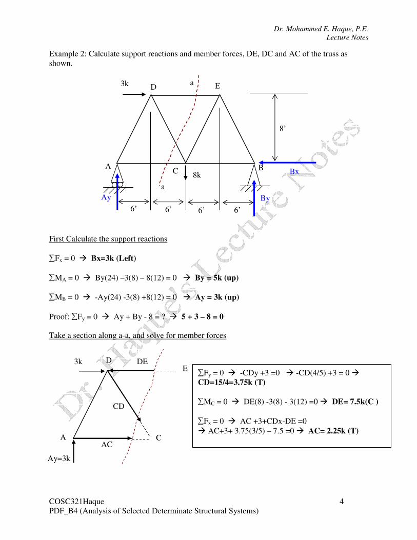
Example 2: Calculate support reactions and member forces, DE, DC and AC of the truss as
shown.
First Calculate the support reactions
∑Fx = 0 � Bx=3k (Left)
∑MA = 0 � By(24) –3(8) – 8(12) = 0 � By = 5k (up)
∑MB = 0 � -Ay(24) -3(8) +8(12) = 0 � Ay = 3k (up)
Proof: ∑Fy = 0 � Ay + By - 8 = ? � 5 + 3 – 8 = 0
Take a section along a-a, and solve for member forces
Bx
8’
6’ 6’ 6’ 6’
8k
3k
A B C
D E
By Ay
a
a
Ay=3k
A
D E
C
3k DE
AC
CD
∑Fy = 0 � -CDy +3 =0 � -CD(4/5) +3 = 0 �
CD=15/4=3.75k (T)
∑MC = 0 � DE(8) -3(8) - 3(12) =0 � DE= 7.5k(C )
∑Fx = 0 � AC +3+CDx-DE =0
� AC+3+ 3.75(3/5) – 7.5 =0 � AC= 2.25k (T)

Dr. Mohammed E. Haque, P.E.
Lecture Notes
COSC321Haque 5
PDF_B4 (Analysis of Selected Determinate Structural Systems)
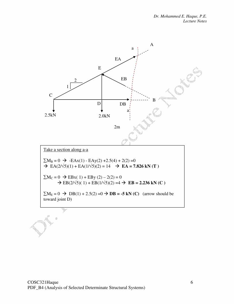
Example 3: Calculate reactions, Ax, Ay and Bx. Find member forces, EA, EB, and DB using
section method.
C
2.5kN 2.0kN
A
D
B
E 2m
2m 2m
Ay
Ax
Bx
a
a
Find out support Reactions:
∑Fy = 0 � Ay= 2.5 + 2 = 4.5 kN (up)
∑MB = 0 � -Ax (2) +2.5(4) + 2(2) =0 � Ax= 7 kN(Right)
∑Fx = 0 � Bx= 7 kN (Left)
Dr. Mohammed E. Haque, P.E.
Lecture Notes
COSC321Haque 6
PDF_B4 (Analysis of Selected Determinate Structural Systems)
2m
C
2.5kN 2.0kN
A
D B
E
EA
a
a
EB
DB
2
1
Take a section along a-a
∑MB = 0 � -EAx(1) - EAy(2) +2.5(4) + 2(2) =0
� EA(2/√5)(1) + EA(1/√5)(2) = 14 � EA = 7.826 kN (T )
∑MC = 0 � EBx( 1) + EBy (2) – 2(2) = 0
� EB(2/√5)( 1) + EB(1/√5)(2) =4 � EB = 2.236 kN (C )
∑ME = 0 � DB(1) + 2.5(2) =0 � DB = -5 kN (C) (arrow should be
toward joint D)
Dr. Mohammed E. Haque, P.E.
Lecture Notes
COSC321Haque 7
PDF_B4 (Analysis of Selected Determinate Structural Systems)
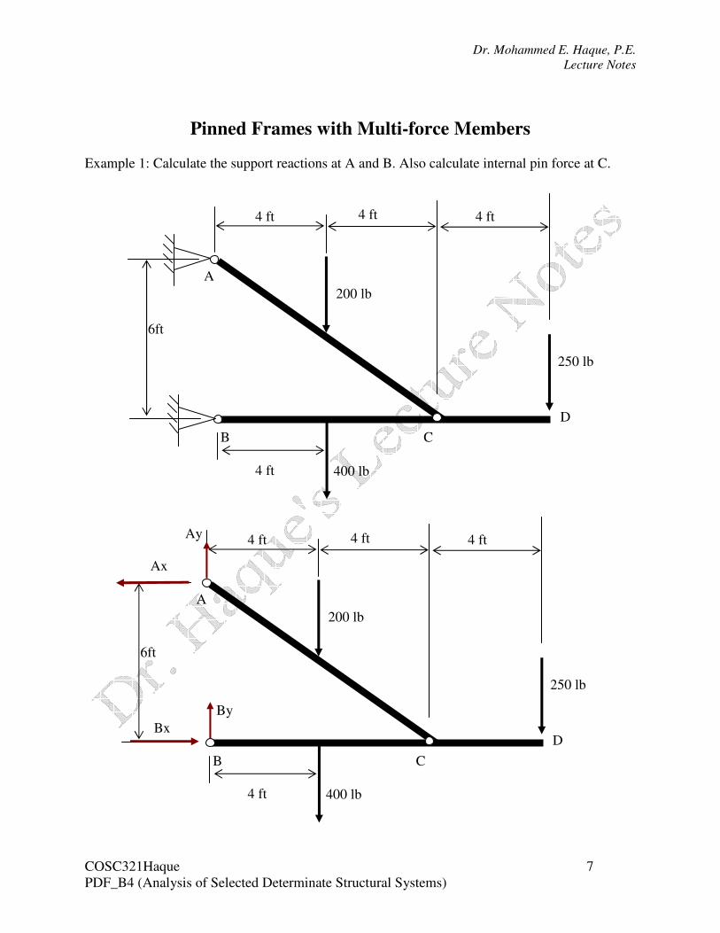
Pinned Frames with Multi-force Members
Example 1: Calculate the support reactions at A and B. Also calculate internal pin force at C.
B
A
C
D
400 lb
200 lb
250 lb
6ft
4 ft 4 ft 4 ft
4 ft
B
A
C
D
400 lb
200 lb
250 lb
6ft
4 ft 4 ft 4 ft
4 ft
Ax
Ay
Bx
By
Dr. Mohammed E. Haque, P.E.
Lecture Notes
COSC321Haque 8
PDF_B4 (Analysis of Selected Determinate Structural Systems)
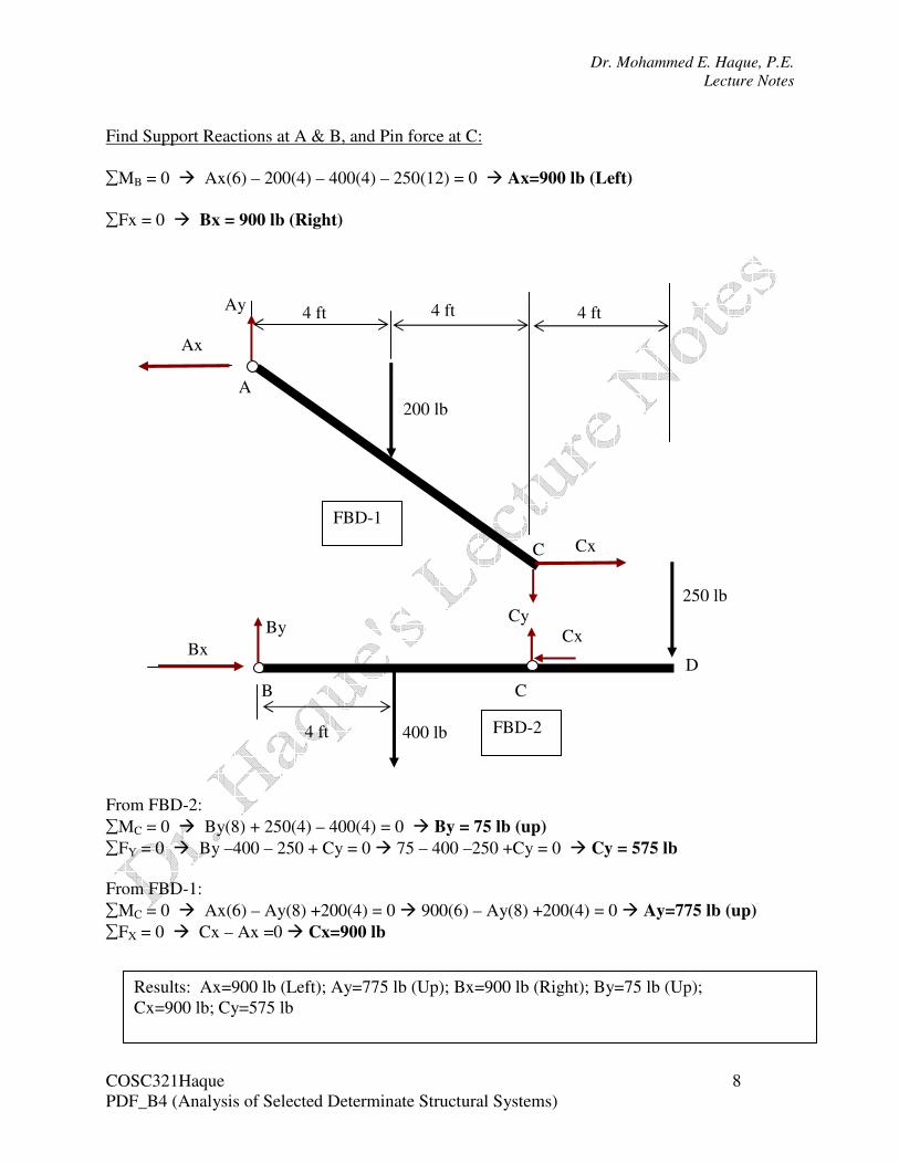
Find Support Reactions at A & B, and Pin force at C:
∑MB = 0 � Ax(6) – 200(4) – 400(4) – 250(12) = 0 � Ax=900 lb (Left)
∑Fx = 0 � Bx = 900 lb (Right)
From FBD-2:
∑MC = 0 � By(8) + 250(4) – 400(4) = 0 � By = 75 lb (up)
∑FY = 0 � By –400 – 250 + Cy = 0 � 75 – 400 –250 +Cy = 0 � Cy = 575 lb
From FBD-1:
∑MC = 0 � Ax(6) – Ay(8) +200(4) = 0 � 900(6) – Ay(8) +200(4) = 0 � Ay=775 lb (up)
∑FX = 0 � Cx – Ax =0 � Cx=900 lb
A
200 lb
4 ft 4 ft 4 ft
Ax
Ay
B C
D
400 lb
250 lb
4 ft
Bx
By Cy
Cx
Cx
C
FBD-1
FBD-2
Results: Ax=900 lb (Left); Ay=775 lb (Up); Bx=900 lb (Right); By=75 lb (Up);
Cx=900 lb; Cy=575 lb
Dr. Mohammed E. Haque, P.E.
Lecture Notes
COSC321Haque 9
PDF_B4 (Analysis of Selected Determinate Structural Systems)
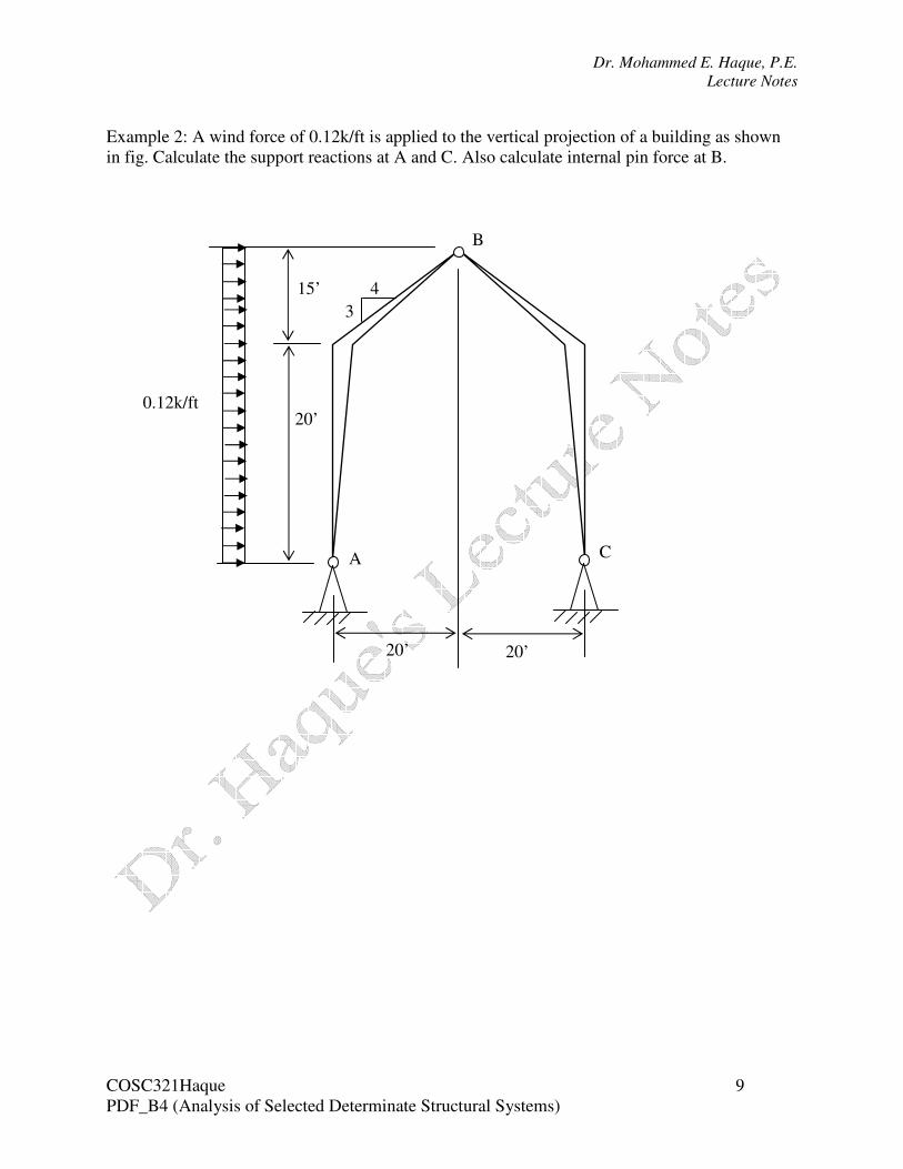
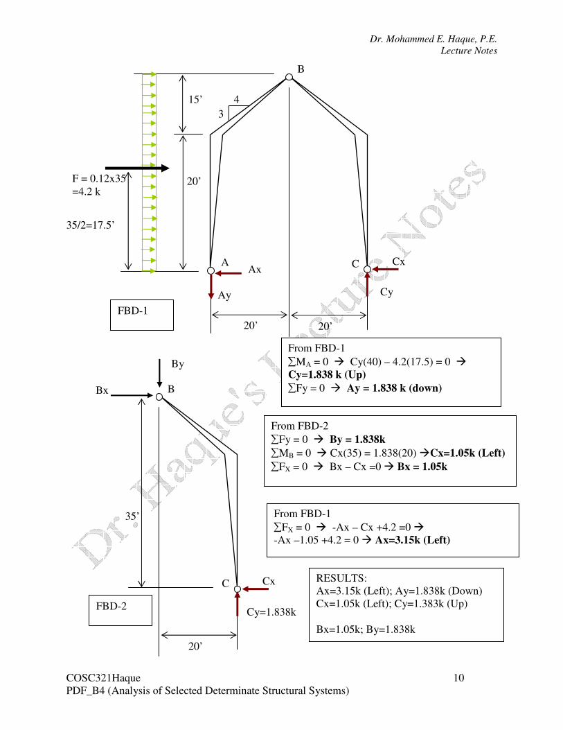
Example 2: A wind force of 0.12k/ft is applied to the vertical projection of a building as shown
in fig. Calculate the support reactions at A and C. Also calculate internal pin force at B.
A C
B
20’
15’
3
4
20’ 20’
0.12k/ft
Dr. Mohammed E. Haque, P.E.
Lecture Notes
COSC321Haque 10
PDF_B4 (Analysis of Selected Determinate Structural Systems)
A C
B
20’
15’
3
4
20’ 20’
F = 0.12x35
=4.2 k
35/2=17.5’
Ax
Ay
Cx
Cy
FBD-1
C
B
35’
20’
Cx
Cy=1.838k FBD-2
Bx
By
From FBD-2
∑Fy = 0 � By = 1.838k
∑MB = 0 � Cx(35) = 1.838(20) �Cx=1.05k (Left)
∑FX = 0 � Bx – Cx =0 � Bx = 1.05k
From FBD-1
∑MA = 0 � Cy(40) – 4.2(17.5) = 0 �
Cy=1.838 k (Up)
∑Fy = 0 � Ay = 1.838 k (down)
RESULTS:
Ax=3.15k (Left); Ay=1.838k (Down)
Cx=1.05k (Left); Cy=1.383k (Up)
Bx=1.05k; By=1.838k
From FBD-1
∑FX = 0 � -Ax – Cx +4.2 =0 �
-Ax –1.05 +4.2 = 0 � Ax=3.15k (Left)
Dr. Mohammed E. Haque, P.E.
Lecture Notes
COSC321Haque 11
PDF_B4 (Analysis of Selected Determinate Structural Systems)
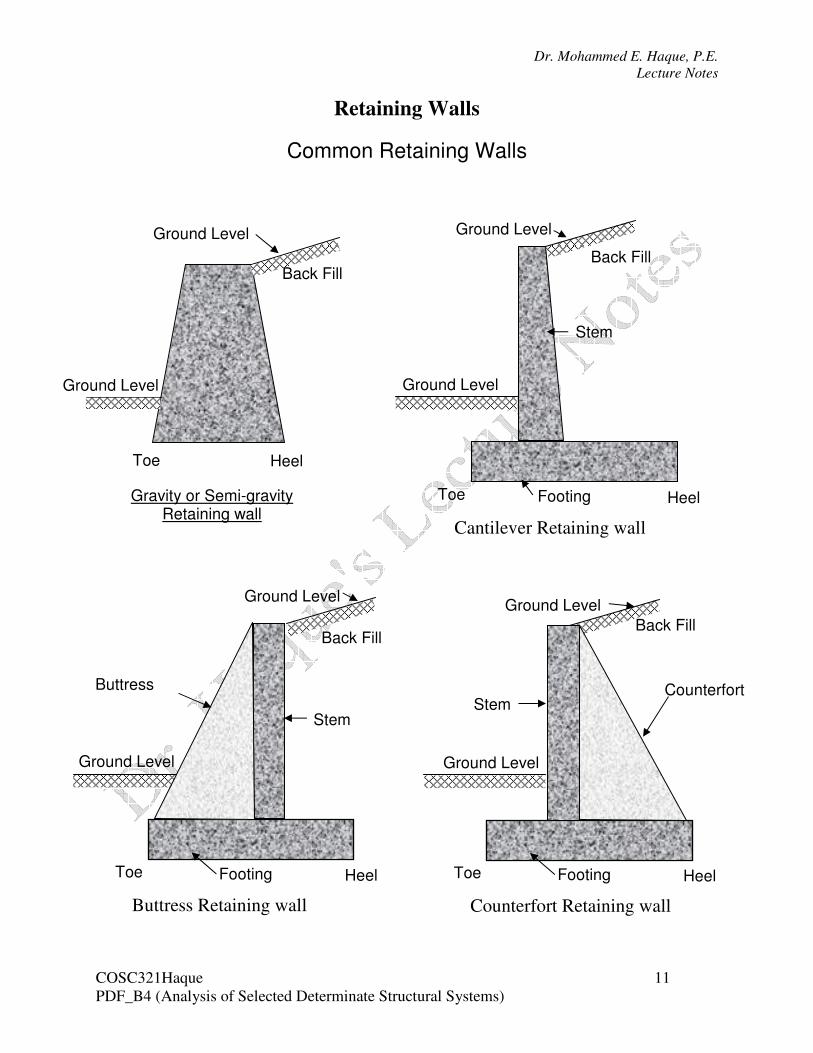
Retaining Walls
Common Retaining Walls
Toe Heel
Gravity or Semi-gravity Retaining wall
Toe Heel
Cantilever Retaining wall
Stem
Footing
Toe Heel
Buttress Retaining wall
Stem
Footing
Buttress
Toe Heel
Counterfort Retaining wall
Stem
Footing
Counterfort
Back Fill Back Fill
Back Fill Back Fill
Ground Level
Ground Level Ground Level
Ground Level
Ground Level
Ground Level
Ground Level
Ground Level
Dr. Mohammed E. Haque, P.E.
Lecture Notes
COSC321Haque 12
PDF_B4 (Analysis of Selected Determinate Structural Systems)
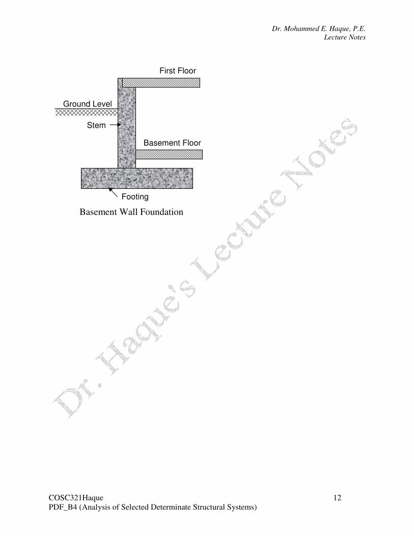
First Floor
Basement Floor
Footing
Stem
Basement Wall Foundation
Ground Level
Dr. Mohammed E. Haque, P.E.
Lecture Notes
COSC321Haque 13
PDF_B4 (Analysis of Selected Determinate Structural Systems)
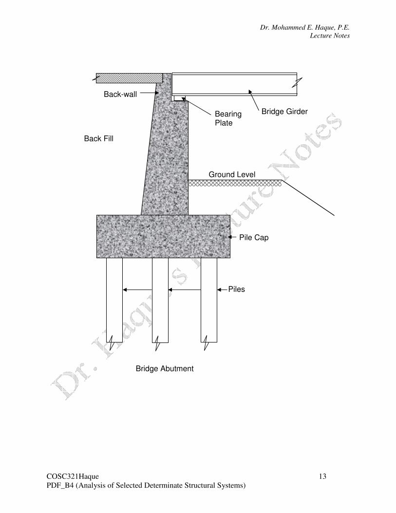
Bearing Plate
Bridge Girder
Back-wall
Piles
Pile Cap
Bridge Abutment
Ground Level
Back Fill
Dr. Mohammed E. Haque, P.E.
Lecture Notes
COSC321Haque 14
PDF_B4 (Analysis of Selected Determinate Structural Systems)
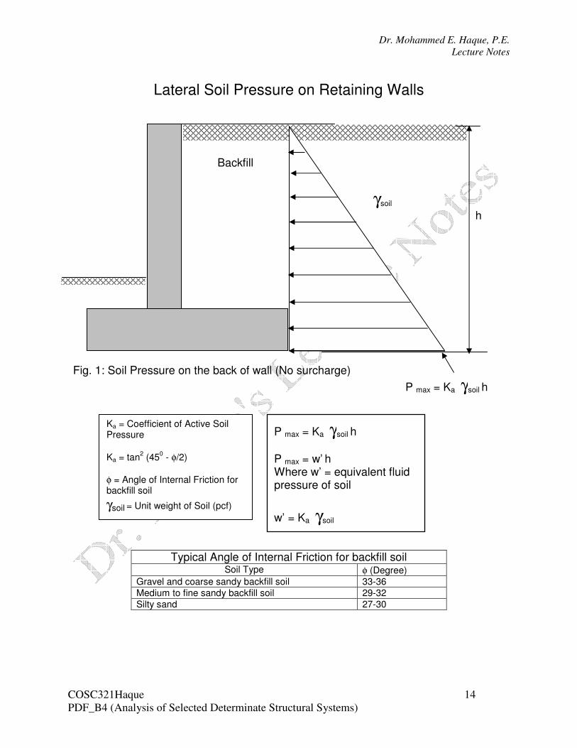
Lateral Soil Pressure on Retaining Walls
Typical Angle of Internal Friction for backfill soil Soil Type φ (Degree)
Gravel and coarse sandy backfill soil 33-36
Medium to fine sandy backfill soil 29-32
Silty sand 27-30
P max = Ka γsoil h
h
γsoil
Backfill
Fig. 1: Soil Pressure on the back of wall (No surcharge)
Ka = Coefficient of Active Soil Pressure
Ka = tan2 (45
0 - φ/2)
φ = Angle of Internal Friction for backfill soil γsoil = Unit weight of Soil (pcf)
P max = Ka γsoil h
P max = w’ h Where w’ = equivalent fluid pressure of soil
w’ = Ka γsoil
Dr. Mohammed E. Haque, P.E.
Lecture Notes
COSC321Haque 15
PDF_B4 (Analysis of Selected Determinate Structural Systems)
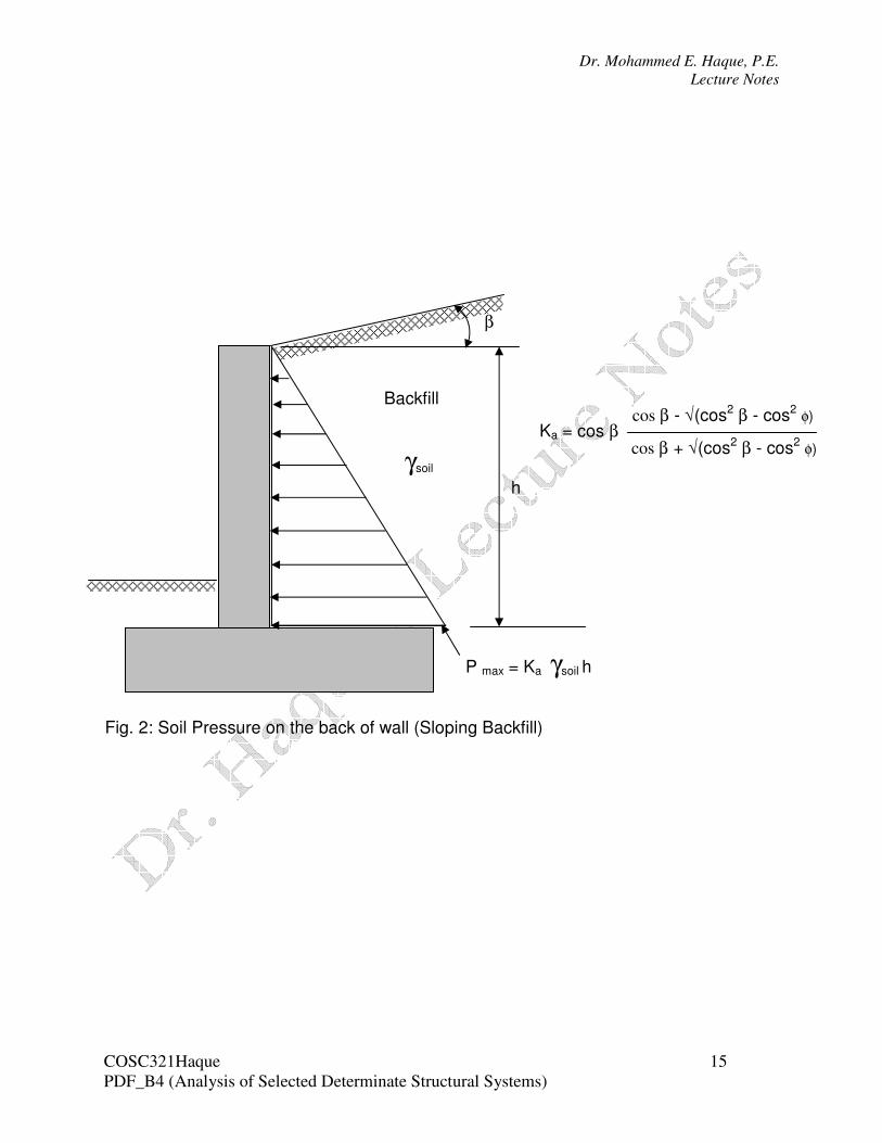
P max = Ka γsoil h
h
γsoil
Backfill
Fig. 2: Soil Pressure on the back of wall (Sloping Backfill)
β
cos β - √(cos2 β - cos2 φ)
cos β + √(cos2 β - cos2 φ)
Ka = cos β
Dr. Mohammed E. Haque, P.E.
Lecture Notes
COSC321Haque 16
PDF_B4 (Analysis of Selected Determinate Structural Systems)
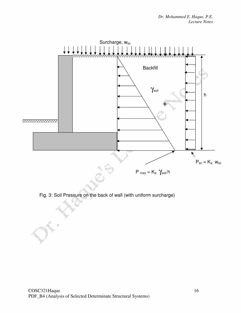
P max = Ka γsoil h
h
Fig. 3: Soil Pressure on the back of wall (with uniform surcharge)
Surcharge, wsc
Psc = Ka wsc
+
γsoil
Backfill
Dr. Mohammed E. Haque, P.E.
Lecture Notes
COSC321Haque 17
PDF_B4 (Analysis of Selected Determinate Structural Systems)
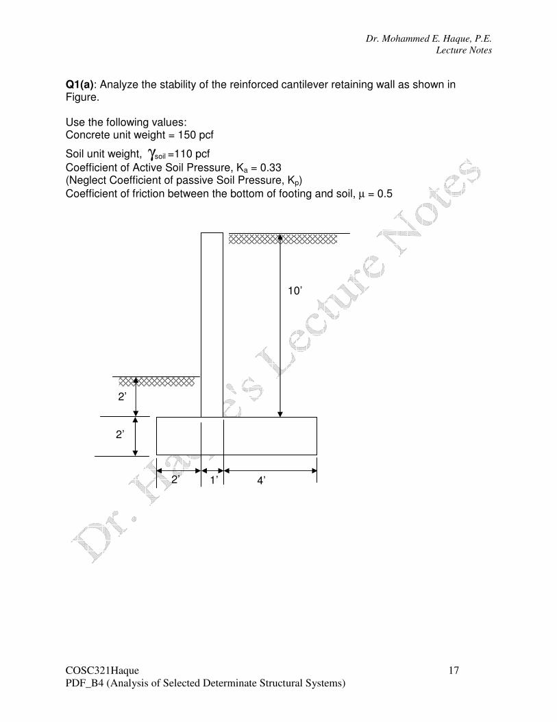
Q1(a): Analyze the stability of the reinforced cantilever retaining wall as shown in Figure. Use the following values: Concrete unit weight = 150 pcf
Soil unit weight, γsoil =110 pcf
Coefficient of Active Soil Pressure, Ka = 0.33 (Neglect Coefficient of passive Soil Pressure, Kp)
Coefficient of friction between the bottom of footing and soil, µ = 0.5
10’
2’
2’
2’ 1’ 4’
Dr. Mohammed E. Haque, P.E.
Lecture Notes
COSC321Haque 18
PDF_B4 (Analysis of Selected Determinate Structural Systems)
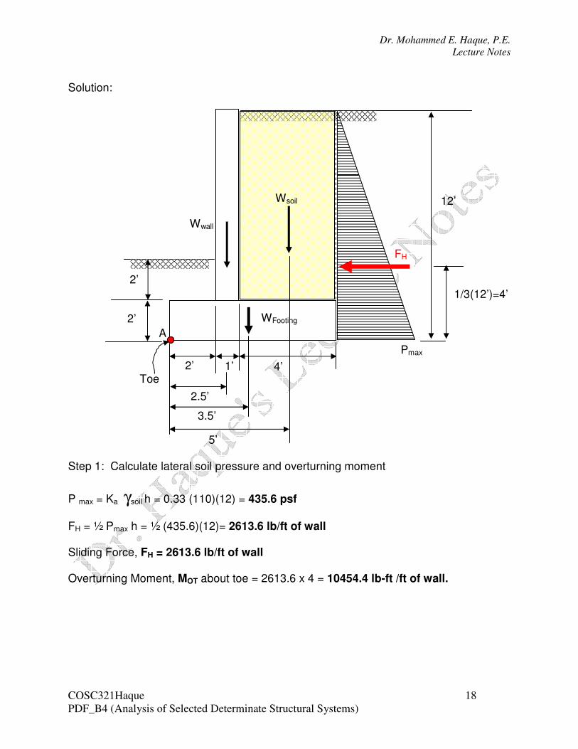
Solution: Step 1: Calculate lateral soil pressure and overturning moment
P max = Ka γsoil h = 0.33 (110)(12) = 435.6 psf
FH = ½ Pmax h = ½ (435.6)(12)= 2613.6 lb/ft of wall Sliding Force, FH = 2613.6 lb/ft of wall Overturning Moment, MOT about toe = 2613.6 x 4 = 10454.4 lb-ft /ft of wall.
12’
2’
2’
2’ 1’ 4’
Wsoil
Wwall
WFooting
FH
Pmax
Toe
A
2.5’
3.5’
5’
1/3(12’)=4’
Dr. Mohammed E. Haque, P.E.
Lecture Notes
COSC321Haque 19
PDF_B4 (Analysis of Selected Determinate Structural Systems)
Step 2: Calculate weights, Resisting Moment, Sliding Resisting Force; Wsoil = (4 x 10)(110) = 4400 lb./ft of wall Wwall = (1 x 10)(150) = 1500 lb / ft of wall WFooting = (2 x 7)(150) = 2100 lb / ft of wall WTotal = 4400 + 1500 + 2100 = 8000 lb / ft of wall Resisting moment , MR about toe = (4400 x 5) + (1500 x 2.5) + (2100 x 3.5)
= 33100 lb-ft/ft of wall
Sliding Resisting Force, FR = µ X WTotal = 0.5 (8000) = 4000 lb Step 3: determining the Factor of Safety (FS) against overturning and sliding. FS OT = MR / MOT = 33100 / 10454.4 = 3.17 > 2.0 OK
FS Sliding = FR / FH = 4000 / 2613.6 = 1.53 > 1.5 OK
Dr. Mohammed E. Haque, P.E.
Lecture Notes
COSC321Haque 20
PDF_B4 (Analysis of Selected Determinate Structural Systems)
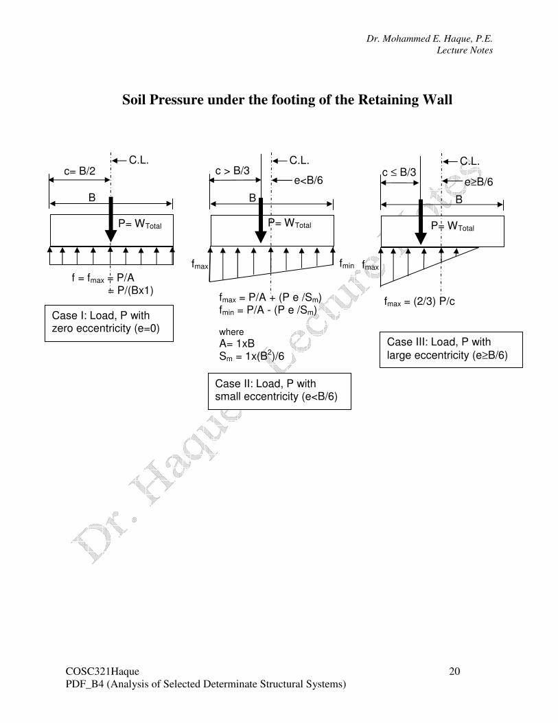
Soil Pressure under the footing of the Retaining Wall f = fmax = P/A = P/(Bx1)
C.L.
B
P= WTotal
c= B/2
Case I: Load, P with zero eccentricity (e=0)
fmax = P/A + (P e /Sm) fmin = P/A - (P e /Sm) where
A= 1xB Sm = 1x(B2)/6
C.L.
B
P= WTotal
c > B/3
Case II: Load, P with small eccentricity (e<B/6)
e<B/6
fmax fmin
fmax = (2/3) P/c
C.L.
B
P= WTotal
c ≤ B/3
Case III: Load, P with
large eccentricity (e≥B/6)
e≥B/6
fmax
Dr. Mohammed E. Haque, P.E.
Lecture Notes
COSC321Haque 21
PDF_B4 (Analysis of Selected Determinate Structural Systems)
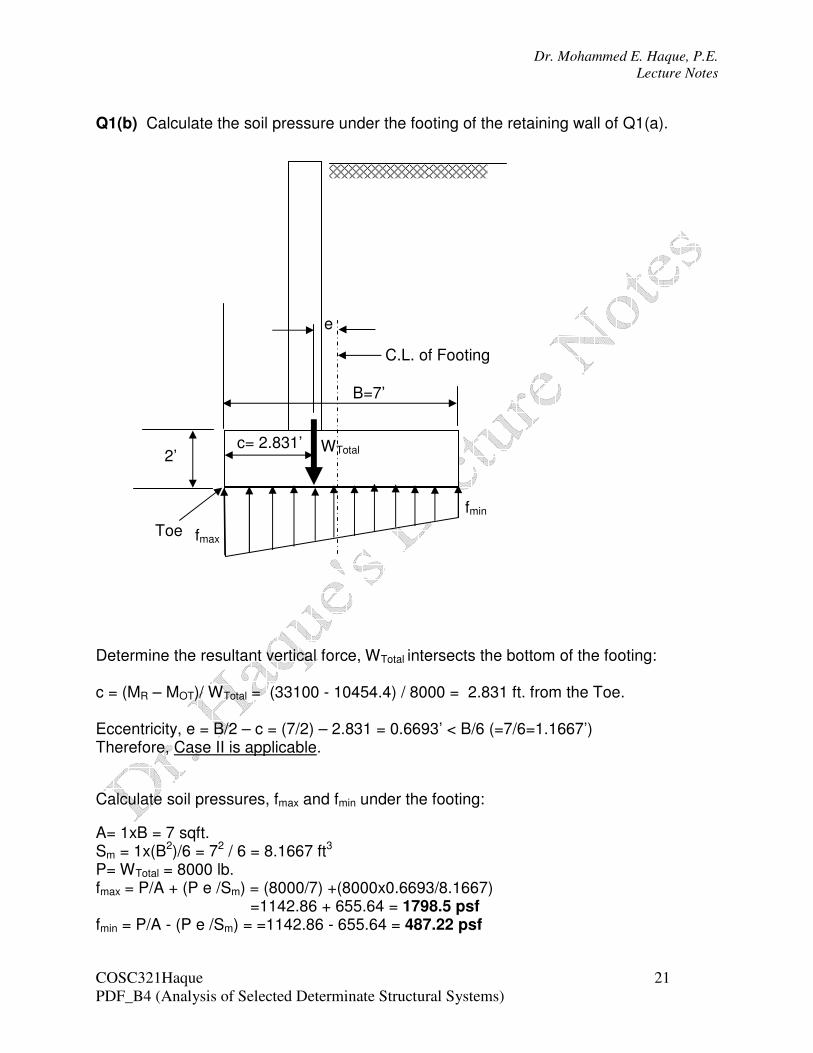
Q1(b) Calculate the soil pressure under the footing of the retaining wall of Q1(a).
Determine the resultant vertical force, WTotal intersects the bottom of the footing: c = (MR – MOT)/ WTotal = (33100 - 10454.4) / 8000 = 2.831 ft. from the Toe. Eccentricity, e = B/2 – c = (7/2) – 2.831 = 0.6693’ < B/6 (=7/6=1.1667’) Therefore, Case II is applicable.
Calculate soil pressures, fmax and fmin under the footing:
A= 1xB = 7 sqft. Sm = 1x(B2)/6 = 72 / 6 = 8.1667 ft3 P= WTotal = 8000 lb. fmax = P/A + (P e /Sm) = (8000/7) +(8000x0.6693/8.1667)
=1142.86 + 655.64 = 1798.5 psf fmin = P/A - (P e /Sm) = =1142.86 - 655.64 = 487.22 psf
C.L. of Footing
c= 2.831’ 2’
fmin
WTotal
B=7’
Toe
e
fmax