analysis of soil-structure interaction by ménard
TRANSCRIPT

International Conference on Geotechnical Engineering ISSMGE Technical Committee 207, Saint Petersburg 2014
1
Analysis of soil-structure interaction by Ménard pressuremeter tests and ground improvement case histories
S. Varaksin ISSMGE TC211 Chairman, France
B. Hamidi GFWA, Australia
ABSTRACT: The pressuremeter is one of the leading tools that allow direct measurement of the soil structure interaction. Its
almost full scale loading of soils during testing, its applicability to most soil types, and recently, to soft rocks has allowed majorprogress in the understanding, design and control of soil improvement, where treated soils will have to meet preset criteria. Structures can be designed based on Menard’s rules ,this with a tested volume allowing the 98 % confidence in predicting the soil structure behavior, which is by far more than current practice. Indeed the approach of Louis Menard directly uses the limit pressure, PLM, as the parameter governing bearing capacity, without relying on failure criteria and hypotheses, and the pressuremeter modulus, EM, is directly related to deviatoric deformation and adopted for volumetric deformations as well. The selected case histories illustrate the essential input of the Menard Pressuremeter in various applications.
KEYWORDS: Menard Pressuremeter, ground improvement, dynamic compaction, dynamic replacement, reclamation, soil-structure interaction
1 INTRODUCTION
The first encounter of the first author with the Menard pressuremter dates back to approximately 40 years ago when, during his military service, he was given the task to perform two borings to the depth of 42 m and to carry out one pressuremeter test every 1.5 m. The tools used were a hand auger, a bentonite hand pump and a tripod with a mechanical winch.
After six months of hard work, he met Louis Menard who laughed about this performance, and then proposed that he join the recently created ground improvement department of Menard’s organization.
1 FIRST STEPS IN GROUND IMPROVEMENT
The construction of the Mandelieu la Napoule development in the French Riviera in 1969 was one of the first opportunities for understanding dynamic compaction. There, Louis Menard proposed to the developer to compact the 110,000 m2 reclaimed site using Menard’s recently invented dynamic compaction technique, and to build his five story buildings using shallow footings rather than implementing the classical and costly piled foundations that had to additionally sustain the negative skin friction created by the fill weight. With Menard’s method, the ground would have indeed become so dense that the required bearing would have become available without the risk of excessive total and differential settlements.
The first English publication of Menard and Broise (1975) proposed a relation between the behaviour of saturated fill under heavy impact and pore water pressure (see Figure 1). At that time, the concept of effective stress was only well understood in academia and still not used in the industry’s common practice. However, Menard was able to implement this
concept into his work and the grid definition and rest period between dynamic compaction works in phases were born.
(a) (b)
Figure 1. (a) changes in the soil after consolidation phase, (b) Variation to a soil subjected to a series of dynamic consolidation passes (Menard, 1975)

International Conference on Geotechnical Engineering ISSMGE Technical Committee 207, Saint Petersburg 2014
2
2 PRESSUREMETER AND SELF BEARING IN FILLS
Although theoretical soil mechanics is well advanced in normally and over consolidated soils, little data and theory is available for recent granular fills that are undergoing deformation under self weight with passage of time. It appears that the pressuremeter is indeed the only testing tool that can quantify the phenomanon of self bearing or creep. Menard (1975) proposed, as a rule of thumb, that the pressuremeter limit pressure, Pl, has to be equal to or greater than 6 bars (600kPa) to reach self-bearing in sands of less than 10 m thickness. As a first approximation, he also proposed to estimate the one-year creep of any soil by:
������ ��
1000
1 � � � 2�
� �2�
(1)
Where w is settlement in cm, h is fill thickness in cm and α is
the structure coefficient variable according to the nature of the soil and the ratio of Menard modulus, EM, to Pl. The unit for Pl in Equation 1 is bars.
Al Quo’a New Township was a new development in the deserts of UAE that was to be constructed on levelled dune sands. While some areas of this 3.8 million m2 site was on competent ground, approximately 1.13 million m2 of the project was located on loose fill with thicknesses similar to Figure 2, and sometimes up to 28 m thick (Hamidi et al., 2010). The project’s developer had first-hand experience of creep, excessive total and differential settlements and building cracking in the first phase of the development, and was seeking a means to ensure that the same problems would not be repeated.
Figure 2. Leveling desert dunes with backfills up to 28 m thick (Hamidi et al., 2010)
It is the authors' experience that the most suitable acceptance criteria for ground improvement projects should be the same as the design criteria (Hamidi et al., 2011). In order to address the bearing, total, differential and creep settlement requirements, the project’s acceptance criteria were defined as summarised in Table 1 and Table 2.
Table 1. Acceptance criteria for villa areas
Safe bearing Self-bearing
Level where parameters prevail
-0.75 to-5.50
m RL
From -5.50
m RL
Pl 750 kPa 600 kPa
EM 4.8 MPa 4 MPa
Table 2. Acceptance criteria for non-villa areas
Safe bearing Self-bearing
Level where parameters prevail
From ±0.00
m RL
From ±0.00
m RL
Pl 600 kPa 600 kPa
EM 4 MPa 4 MPa
Dynamic compaction was implemented in the project using
pounders weighing up to 25 tons to treat more than 90% of the loose fill. The excessive treatment depth of the remaining 10% of the project required the implementation of heavier pounders; hence the MARS (Menard Accelerated Release System) that is shown in Figure 3 was developed to drop a 35 ton pounder in cable-less free fall. This release system was able to self-attach itself to the pounder at the end of each drop cycle.
Figure 3. MARS pounder release system (Hamidi et al., 2010)
In addition to the 50 pressuremeter tests that were carried out before dynamic compaction, to confirm the thickness of loose fill over this vast site, an affordable and innovative method of quick probing was used in this project. Rather than performing thousands of conventional tests, such as CPT, that would have required a long execution time and would have resulted in considerable costs, a vertical drain installation rig was mobilised and the mandrel tip pressure was recorded. Although this testing method cannot be used to estimate bearing capacity and settlements, it was never-the-less an affordable and useful tool for determining the loose fill thickness. At the end of works 200 pressuremeter tests, such as shown in Figure 4, were performed to confirm that acceptance had been achieved. A comparison of pre and post dynamic compaction limit pressures is given in Figure 5.
Varaksin et al. (2005) used the pressuremeter test results to estimate the fill’s creep using Equation 1 for a period of one year and then extended it to a period of 50 and 70 years by a decreasing logarithmic law. The settlement, w, for any year, n, and for a total of t years for reaching self-bearing status will be:
� � ������ln� � 1�
� � 1 (2)

International Conference on Geotechnical Engineering ISSMGE Technical Committee 207, Saint Petersburg 2014
3
Varaksin et al. (2005) also used Menard’s empirical idea of
limit pressure doubling for every 3% of strain to estimate the amount of dynamic compaction induced subsidence to reach self-bearing. Hamidi et al. (2010) formulated this concept:
Figure 4. Pressuremeter testing
Figure 5. Comparison of typical pre and post dynamic compaction limit pressures in Al Quo’a (Varaksin et al., 2005)
� �
log���� ��� � �� !
"#$
log2 %
(3)
ε= strain (Pl)i= limit pressure before soil improvement (Pl)j= limit pressure after soil improvement a= percentage of strain induced for doubling of the Pl (3%) Ground improvement induced subsidence, s, can then be
estimated based on the increase in Pl values:
& = ' ℎ(�(()�,+
= %log2 ' ℎ(()�,+
log����P-�. �P-�/!
"#$
0
(4)
m= number of pressuremeter tests in the borehole within the
improvement zone (i.e. the depth where Pl has increased), and hk is the testing interval length.
This concept was further extended to estimate the increase in Pl (Hamidi et al., 2010a) and EM (Hamidi et al., 2011a) in depth using dynamic compaction subsidence.
3 PRESSUREMETER AND DEEP RECLAMATIONS
As shown in Figure 6, Tsing Yi Oil Terminal in Hong Kong includes 39 steel tanks, 20 m high and up to 46 m in diameter. This 8 hectare faciltiy has been built on a 40 m deep dredged reclamation formed predominantly of hydraulically placed sand fill (Hendy and Muir, 1997).
Figure 6. Tsying Yi Oil Terminal
The soft clay and the base sand were dredged up to 40 m depth, a stone dyke was built to contain the fill and ground improvement by vibro compaction and surcharging until total stabilisation of the fill was planned. The project specification allowed the surcharge to be removed only if no settlement was recorded during a one month period. This was a potential risk for the project that was already bound by a tight schedule.
The settlement criteria specified by the tank fabricators limited total long term settlement at the tanks’ shells to 150 mm and the long term differential settlement around the shell perimeters and across the diameters to 1:360 and 1:80, respectively. Settlement limits related to the design life of 50 year design life of the tanks, including hydrotest under a full tank loading.
Thus, an alternative construction method using dynamic consolidation was proposed by the contractor. In the new scheme the fill mass was improved by dropping pounders weighing up to 40 from as high as 40 m. The prints were backfilled with rock and further compacted with the same equipment to create a stiffened raft.
Pressuremeter tests were performed in the rock columns and the sand fill and settlements were predicted using finite element analysis based on a medium of varying stiffness with depth over a rigid base. The D-60 rules (Menard, 1975) were also used and tank settlements of 4 to 7 cm were predicted. Hydrotest settlement data showed comparable results with the analytical estimates. The most critical tank was No. 1311 which was located on a fill with a variable thickness of 20 m from one side to the other side and a maximum fill thickness of 40 m. Hendy and Muir (1997) report the settlement of this 46 m diameter tank during the hydrotest to have been from 55 to 77 mm. The pressuremeter showed to be the ideal tool for measuring the required parameters in the rock columns and the compacted sand fill.
International Conference on Geotechnical Engineering ISSMGE Technical Committee 207, Saint Petersburg 2014
4
4 PRESSUREMETER FOR PRE-TEST, DESIGN AND SIMPLIFIED CRITERIA
The 5.6 million m2 King Abdulla University of Science and Technology (KAUST) is located in Rabigh on the coast of the Red Sea and near the city of Jeddah in Saudi Arabia. KAUST, originally anticipated to have buildings with at most two to three storeys. The project was fast track and master planning, architectural and structural design and construction all had to be completed in less than three years. Thus there was great need for flexibility, coordination and overlapping of tasks (Hamidi et al., 2010b).
The preliminary geotechnical investigation that was carried out rather sparingly indicated that the ground was very heterogeneous loose or soft soils with rapid variations of ground conditions within short distances of even 10 m. This investigation and further testing during the works indicated that more than 2,600,000 m2 of the construction area was to be built on soil consisting of up to 9 m of loose silty sand or soft sandy silt that is locally called sabkah. A schematic cross section of the site is shown in Figure 7).
As the investigation was not able to clearly define the soil profiles and consequently the ground improvement method to be applied, a dynamic reconnaissance phase was adopted by dropping a 20 ton pounder from 20 m and visual observation.
Figure 7. Schematic cross section of the KAUST ground conditions (Hamidi et al., 2010b)
Pressuremeter tests provided the parameters for the design of footings on sand or silt. As the buildings and thus footing locations were not defined at that phase, a 2 m thick sand platform was allowed on top of the silt to ensure the distribution of loads to dynamic replacement columns by arching.
The design and construct ground improvement proposal that met the project manager’s technical requirements, schedule and budget was based on the below design criteria:
o Footing location: Any place within the treatment area o Maximum footing load: 1,500 kN o Allowable bearing capacity: 200 kPa o Maximum total settlement: 25 mm o Maximum differential settlement between two adjacent
footings: 1/500 o Liquefaction mitigation for an earthquake with peak
ground acceleration equal to 0.07g o Level: 0.8 m below final ground level, but in any case at
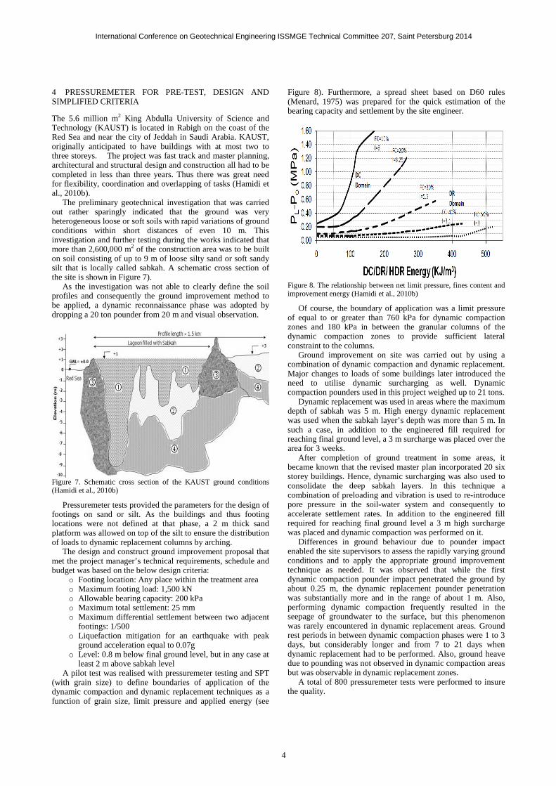
least 2 m above sabkah level A pilot test was realised with pressuremeter testing and SPT
(with grain size) to define boundaries of application of the dynamic compaction and dynamic replacement techniques as a function of grain size, limit pressure and applied energy (see
Figure 8). Furthermore, a spread sheet based on D60 rules (Menard, 1975) was prepared for the quick estimation of the bearing capacity and settlement by the site engineer.
Figure 8. The relationship between net limit pressure, fines content and improvement energy (Hamidi et al., 2010b)
Of course, the boundary of application was a limit pressure of equal to or greater than 760 kPa for dynamic compaction zones and 180 kPa in between the granular columns of the dynamic compaction zones to provide sufficient lateral constraint to the columns.
Ground improvement on site was carried out by using a combination of dynamic compaction and dynamic replacement. Major changes to loads of some buildings later introduced the need to utilise dynamic surcharging as well. Dynamic compaction pounders used in this project weighed up to 21 tons.
Dynamic replacement was used in areas where the maximum depth of sabkah was 5 m. High energy dynamic replacement was used when the sabkah layer’s depth was more than 5 m. In such a case, in addition to the engineered fill required for reaching final ground level, a 3 m surcharge was placed over the area for 3 weeks.
After completion of ground treatment in some areas, it became known that the revised master plan incorporated 20 six storey buildings. Hence, dynamic surcharging was also used to consolidate the deep sabkah layers. In this technique a combination of preloading and vibration is used to re-introduce pore pressure in the soil-water system and consequently to accelerate settlement rates. In addition to the engineered fill required for reaching final ground level a 3 m high surcharge was placed and dynamic compaction was performed on it.
Differences in ground behaviour due to pounder impact enabled the site supervisors to assess the rapidly varying ground conditions and to apply the appropriate ground improvement technique as needed. It was observed that while the first dynamic compaction pounder impact penetrated the ground by about 0.25 m, the dynamic replacement pounder penetration was substantially more and in the range of about 1 m. Also, performing dynamic compaction frequently resulted in the seepage of groundwater to the surface, but this phenomenon was rarely encountered in dynamic replacement areas. Ground rest periods in between dynamic compaction phases were 1 to 3 days, but considerably longer and from 7 to 21 days when dynamic replacement had to be performed. Also, ground heave due to pounding was not observed in dynamic compaction areas but was observable in dynamic replacement zones.
A total of 800 pressuremeter tests were performed to insure the quality.

International Conference on Geotechnical Engineering ISSMGE Technical Committee 207, Saint Petersburg 2014
5
5 NEW VERSATILE TECHNIQUES FOR DIFFICULT SOILS
The development of a new container terminal in Southeast Asia was the opportunity to make a compromise between pressuremeter and Mohr Coulomb approaches.
According the original design the soft marine clay at the seabed was to be dredged down to the depth of 30 m below sea level where the shear strength of the stiff clay exceeded 250 kPa. The excavated key was to be then backfilled with sand and compacted using vibro compaction under 3 m of additional overburden sand fill. Next, the surcharge had to be removed, a rubble mound was to be placed over the sand key, and as shown in Figure 9, finally caissons were to be sunk onto the mound.
Figure 9. Cross section of container terminal based on original foundation concept
While the clay at dredge level was initially very stiff, dredging works and cutting into the clay softened the upper 1 to 1.5 m of the exposed clay surface and post dredging CPT tests performed before the removal of the overburden sand fill indicated that the clay’s shear strength had dropped to about one third of its original value; i.e. to approximately 80 kPa (Hamidi et al., 2010c). Further testing at later stages by the pressuremeter test suggested that the shear strength had even further reduced at some points to as low as 16 kPa.
Dynamic replacement was used as an alternative method to treat the softened clay layer. In the proposed dynamic replacement methodology it was assumed that a 1.8 m thick granite rock fill layer would be placed over the soft clay layer. The blanket material was chosen in such a way that 30% of the stone diameters were from 150 to 200 mm and the remaining 70% were from 200 to 300 m. The rock columns were designed to be 2 m in diameter, in a 4.5 m grid and with a replacement ratio of 15%.
A pounder weighing 38.5 tons was specifically designed and fabricated for the project. This pounder was grater shaped to allow the passage of water through the pounder with the least resistance. It was also with dual side functionality; i.e. it was 1.7 m by 1.7 m on one side and used for driving rock dynamically into the clay and 2.3 m by 2.3 m on the side to dynamically compact the rock blanket. Figure 10 shows this marine pounder.
The self-bored slotted tube or Staf technique (Arsonnet et al., 2005) was utilised from a jack up barge, to perform the pressuremeter tests down to a depth of more than 30 m. The technique consists of sealing a casing to the sea floor and driving a BX size slotted casing with advanced drilling and by utilising an eccentric bit. The slotted casing is advanced to the required depth, the bit is removed and the pressuremeter probe is inserted to depth. After the test, the slotted casing is jacked up one meter and the next test is performed. Figure 11 shows the Staf drag bits that can either have blades or buttons.
Since the stability analysis was performed using the classical the Mohr Coulomb failure criteria, the friction angle and cohesion were necessary for the stability analysis.
Shear strength, c, can be estimated from the pressuremeter test by (Menard, 1970):
1 = 2∗5.5 (5)
Figure 10. Specially designed multi-purpose marine pounder (Chu et al., 2009)
Pl*= net limit pressure and can be calculated from
Pl*= Pl- Po (6)
Po= at rest horizontal earth pressure at the test level at the
time of the test. The internal friction angle, φ, for sands can be estimated in
sands from the pressuremeter test by (Menard, 1970):
�∗ = 2.5 6 2789::
(7)
Figure 11. Staf drag bit
Equation 7 is not applicable to rock; hence a method was devised by Yee and Varaksin to develop an equation for rock. For this purpose, a test pit was dug out and backfilled with rock in a loose state. The internal friction angle was determined with failure loading and the limit pressure was measured. A point was set in the diagram of Figure 12, and from this point a curve was drawn parallel to Menard’s limit pressure-friction angle curve to develop the proposed formula of Equation 8.
�∗ � 4 6 2
78:<=
(8)

International Conference on Geotechnical Engineering ISSMGE Technical Committee 207, Saint Petersburg 2014
6
Pressuremeter tests were carried out at 29 different locations
that also included cyclic tests. As reported by Yee and Varaksin (2012) the ratios of reload to Menard modulus was in the range of 3.5 to 4.2 which agrees with the suggested value of 4 for compacted gravel and rock (Menard, 1975). Based on Equation 8, the internal friction angle of the rock after compaction was interpreted to be from 47 to 49o, with an average value of 48.5o, which satisfied the design requirement of 45o.
Figure 12. Developing a method for estimating rock friction angle from the limit pressure
6 CONCLUSION
The pressuremeter has not only been a tool for the design and quality control of ground improvement works, which is mostly adapted to non- cohesive soils and the only method for fills.
In the authors' opinion, the pressuremeter is the most versatile field test and proven method of analysis that can satisfy not only the geotechnical engineers’ requirements, but also that of the constructors.
Specifying ground improvement acceptance criteria based on design criteria; i.e. bearing capacity, settlement, etc. is a much more realistic and smarter approach than stipulating testing values. In addition specifying calculation methods such as what has been proposed by Menard (1975) makes interpretation of data very clear, without leaving technical and contractual loose ends in a project.
7 REFERENCES
Arsonnet, G., Baud, J.P., and Gambin, M.P. 2005. Pressuremeter Tests Inside a Self-Bored Slotted Tube (STAF). International Symposium 50 Years of Pressuremeters (ISP5- Pressio 2005). Paris, pp. 31-45.
Chu, J., Varaksin, S., Klotz, U. & Mengé, P. 2009. State of the Art Report: Construction Processes. 17th International Conference on Soil Mechanics & Geotechnical Engineering: TC17 meeting ground improvement, Alexandria, Egypt, 7 October 2009, 130.
Hamidi, B., Nikraz, H., and Varaksin, S. 2010. Soil Improvement of a Very Thick and Large Fill by Dynamic Compaction. 3rd International Conference on Problematic Soils (PS10), Adelaide, pp. 129-138.
Hamidi, B., Varaksin, S., and Nikraz, H. 2010a. Predicting Soil Parameters by Modelling Dynamic Compaction Induced Subsidence. 6th Australasian Congress on Applied Mechanics (ACAM6). Engineers Australia, Perth, Australia, p. Paper 1150.
Hamidi, B., Varaksin, S., and Nikraz, H. 2010b. Implementation of Optimized Ground improvement techniques for a Giga Project. GeoShanghai 2010 Conference, ASCE Geotechnical Special Publication No 207: Ground Improvement and Geosynthetics, Shanghai, pp. 87-92.
Hamidi, B., Yee, K., Varaksin, S., Nikraz, H., and Wong, L.T. 2010c. Ground Improvement in Deep Waters Using Dynamic Replacement. 20th International Offshore and Polar Engineering Conference. Beijing. 20-26 June, pp. 848-853.
Hamidi, B., Nikraz, H., and Varaksin, S. 2011. Ground Improvement Acceptance Criteria. 14th Asian Regional Conference on Soil Mechanics and Geotechnical Engineering Hong Kong, Paper No. 404.
Hamidi, B., Varaksin, S., and Nikraz, H. 2011a. Predicting Menard Modulus using Dynamic Compaction Induced Subsidence. International Conference on Advances in Geotechnical Engineering (ICAGE). Edited by M. Shahin and H. Nikraz. Perth. 7-11 November, pp. 221-226.
Hendy, M.S., and Muir, I.C. 1997. Experience of Dynamic Replacement on a 40 m Deep Reclamation in Hong Kong. Third International Conference on Ground Improvement Geosystems: Ground Improvement Geosystems - Densification and Reinforcement. Edited by M.C.R. Davies and F. Schlosser. London. 3-5 June 1997. Thomas Telford, pp. 76-80.
Menard, L. 1970. Détermination de la Poussée Exercée par un Sol sur une Paroi de Soutènement. Publication D/38/70.
Menard, L. 1975. The Menard Pressuremeter: Interpretation and Application of Pressuremeter Test Results to Foundation Design, D.60.AN. Sols Soils, 26: 5-43.
Menard, L., and Broise, Y. 1975. Theoretical and Practical Aspects of Dynamic Compaction. Geotechnique, 25(1): 3-18.
Varaksin, S., Hamidi, B., and D'Hiver, E. 2005. Pressuremeter Techniques to Determine Self Bearing Level and Surface Strain for Granular Fills after Dynamic Compaction. International Symposium 50 Years of Pressuremeters (ISP5- Pressio 2005), Paris, pp. 687-.
Yee, K., and Varaksin, S. 2012. Ground Reinforcement in Deep Water. International Conference on Ground Improvement and Ground Control - Transport Infrastructure Development and Natural Hazards Mitigation (ICGI2012). Wollongong, Australia. 30 October - 2 November, Vol.2, pp. 575-585.
Varaksin, S., Hamidi, B. 2013. Pressuremeter for design and acceptance of challenging ground improvement works. Proceedings of the 18th International Conference on Soil Mechanics and Geotechnical Engineering, Paris 2013 (Parallel session ISP6)