analysis of stress and strain ii - deukisi.deu.edu.tr/emine.cinar/asm16-analysis of stress...
TRANSCRIPT

ANALYSIS OF STRESS AND STRAIN II

MOHR’S CIRCLE FOR PLANE STRESS
If we were only interested in obtaining the normal stress and the shear stress (s, t) on a single
surface, say the x' surface than s and t would be equal to
tssttsss 2222 sincoscossin,sincos2sincos xyyxxyyx
These equations can be rewritten using the trigonometric identities
2cossincos2sin21
cossin
22cos1
sin2
2cos1cos
22
22
So s and t can be written as
tss
ttssss
s 2cos2sin2
,2sin2cos22 xy
yx
xy
yxyx
These are parametric equations which represents a circle in s, t space where is the
parameter. Rearranging the terms give
2
2
2
2
22 xy
yxyxt
sst
sss
x
yR

2
2
2 xy
yxR t
ss
This equation represents the equation of a circle in s, t space where
the radius is
and the center of the circle is displaced in the positive s direction by the average of the
normal stress
2
yx
ave
sss
and 222
Rave tss
From the circle it can be observed that the
maximum and minimum values of s and t are
2
2
minmax 22 xy
yxyx
ave R tssss
ss
and 2
2
minmax 2 xy
yxt
sst
It is important to note that the maximum and
minimum values of s and t determined here may
not be the absolute maximums or minimums. Figure 1 Mohr’s circle for plane stress
If one were to plot the circle graphically with the coordinate axes s and t positive to the right
and up, respectively, the circle would graph 2 in the clockwise direction as increased in the
counterclockwise direction, Figure 1. This opposing direction can lead to errors, therefore,
plotting positive t downwards can prevent errors.

THREE DIMENSIONAL STRESS TRANSFORMATION SIMPLIFIED
The total shear stress acting on a surface depends only on the
particular surface as defined by the surface normal (Figure 2).
If we redefine the surface normal by the n axis, where the
direction cosines of the normal are
zz
yy
xx
n
n
n
cos
cos
cos
The normal stress will be equal to
xzzxzyyzyxxyzzyyxx nnnnnnnnn tttssss 222222
The total shear stress can be found from a summation of forces. The total force in the x
direction due to the stresses on the orthogonal surfaces is
zzxyxyxxx AAAF tts zzyyxx nAAnAAnAA 000 ,, and
zzxyxyxxx nnnAF tts 0
Likewise the forces in the y and z directions due to stresses on the orthogonal surfaces are
zzyyzxzxz
zyzyyxxyy
nnnAF
nnnAF
stt
tst
0
0
Figure 2 Mohr’s circle for plane stress
n
x
y
z
x
y
z
xs
zst
ys
xytyztzxt
ts

The magnitude of t can be found readily since for equilibrium the magnitude of the forces on the
oblique surface must balance the magnitude of forces on the orthogonal surfaces
. t is obtained as
2/122
0 ts A
2/1222
zyx FFF
2/12222
sstttstttst zzyyzxzxzyzyyxxyzzxyxyxx nnnnnnnnn
The direction cosines establishing the direction of t can be defined as tx, ty and tz. For equilibrium in x
direction
000 xxx FnAtA st
Solving for tx
x
xx n
A
Ft s
t 0
1Substituting for Fx gives
zzxyxyxxx nnnt ttsst
1
Likewise for ty and tz
zzyzyxzxz
zyzyyxxyy
nnnt
nnnt
ssttt
tsstt
1
1
n
x
y
z
x
y
z
xs
zst
ys
xytyztzxt
ts

Example
The state of stress at a particular point relative to the xyz coordinate system is given by the
stress matrix
Determine the normal stress and the magnitude and direction of the shear stress on a surface
intersecting the point and parallel to the plane given by the equation
MPa
3507
0107
7714
s
932 zyx

Example 2.1
A point in a state of plane stress is isolated by three surfaces as shown. Determine the values
of s and t using transformation equations and the Mohr’s circle.

The case cannot happen since
PRINCIPLE STRESSES
Principle stresses exist on mutually orthogonal surfaces that contain no shear stress. The
three principle stresses are denoted as s1, s2 and s3, as s1 > s2 > s3. If two of the principle
stresses are equal, there will exist an infinite set of surfaces containing these principle
stresses, where the normals of these surfaces are perpendicular to the direction of the third
principle stress. If all three principle stresses are equal, a hydrostatic state of stress exists and
regardless of orientation, all surfaces contain the same principle stress with no shear stress. If
we assume that on the oblique surface the shear stress
t is zero, than s will be a principle stress denoted by sP.
The components of the force on the oblique surface in
x,y and z directions are
For equilibrium etc. This results in
zPz
yPy
xPx
nAF
nAF
nAF
0
0
0
s
s
s
,0 xx FF
0
0
0
zPzyyzxzx
zyzyPyxxy
zzxyxyxPx
nnn
nnn
nnn
sstt
tsst
ttss
0 zyx nnn 1222 zyx nnn
n
x
y
z
x
y
z
xs
zst
ys
xytyztzxt
ts

This is a cubic equation in the unknown sP, where three solutions result in the three
principle stresses s1, s2 and s3. It can be shown that the principle stresses exist on surfaces
for which the normal stress is stationary. This means that at least one of the principle
stresses is a maximum and at least one is a minimum.
The direction cosines nx, ny and nz associated with a specific principle stress will not be
independent of each other.
In order to avoid the zero solution of the direction cosines the determinant of the coefficients
nx, ny and nz is equated to zero.
Resulting in
02 222
22223
xyzzxyyzxxyzxyzzyx
PxyzxyzxzzyyxPzyxP
tstststttsss
stttsssssssssss
0
Pzyzzx
yzPyxy
zxxyPx
sstt
tsst
ttss

Example
For the stress matrix given below, determine the principle stresses and the direction cosines
associated with the normals to the surfaces of each principle stress.
MPa
021
201
113
s

Stress Invariants
The solutions of sP are independent of the coordinate system used to define the coefficients of
the cubic equation of sP. Therefore the coefficients of sP are constant and are referred to as
the stress invaraints.
02 222
22223
xyzzxyyzxxyzxyzzyx
PxyzxyzxzzyyxPzyxP
tstststttsss
stttsssssssssss
zyzxz
yzyxy
xzxyx
xyzzxyyzxxyzxyzzyx
xyzxyzxzzyyx
zyx
PPP
I
or
I
I
I
III
stt
tst
tts
tstststttsss
tttssssss
sss
sss
3
222
3
222
2
1
12
2
1
3
2
0

MOHR’S CIRCLE IN THREE DIMENSIONS
An element undergoing a general state of three dimensional stress can be
transformed to an element containing only principle stresses s1, s2 and s3
acting along axes 1, 2 and 3, Figure 3. A transformation of stresses in the
12 plane depends only on s1 and s2 ; in the 23 plane depends only on s2
and s3; in the 31 plane depends only on s3 and s1. This means that for
each case, a plane stress analysis describes the state of stress in each of
the three planes and three Mohr’s circles can be constructed to portray
each case shown in Figure 4 (a). Furthermore, it will be shown that all
possible states of stress (s, t) exist either on the circles or within the
shaded are shown in Figure 4 (b).
Figure 3 Principle stress state
For the element in Figure 3 let n1, n2 and n3 be the
direction cosines of an arbitrary surface relative to the 1,
2 and 3 axes, respectively. We can write,
12
3
2
2
2
1
222
3
22
2
22
1
2
2
33
2
22
2
11
321
nnn
nnn
nnn
stsss
ssss
Figure 4 3D Mohr’s circle

These equations can be arranged to form three equations where each equation is
written exclusively in terms of each direction cosine. This can be done by solving the
above simultaneous equations for and . Using Cramer’s rule
Expanding each determinant with respect to the third row
2
3n
Figure 4 3D Mohr’s circle
2
2
2
1 , nn
111
111
2
3
2
2
2
1
321
2
3
2
2
2232
2
1
sss
sss
ssst
sss
n
2
12
2
21
2
13
2
31
2
23
2
32
22
2
2
2
22
3
2
3
2
23
2
322
1ssssssssssss
stsssstsssssss
n
Reducing to 323121
2
23
22
3232232
1
1sssssssss
stsssssss
n
and
3121
2
322
1 ssss
tssss
n
12
3
2
2
2
1
222
3
22
2
22
1
2
2
33
2
22
2
11
321
nnn
nnn
nnn
stsss
ssss

Cross multiplication results in
In a similar manner solving for n2 and n3, the following equations are obtained
Figure 4 3D Mohr’s circle
The equation for the Mohr’s circle connecting s2 and s3 can be obtained as
and
3121
2
1
2
32 sssstssss n
The first term on the left side can be written as
2
32
2
3232 22
sssssssss
2
323121
2
1
2
2
32
22
sssssst
sss n
2
213231
2
3
2
2
21
2
132123
2
2
2
2
13
22
22
sssssst
sss
sssssst
sss
n
n
2
23
2
322
2
32
22R
sst
sss
R23 is the radius of the s2 , s3 circle. Other radii can be determined similarly.

Maximum Shear Stress
Based on the observations on Mohr’s circles in three dimensions the
maximum and minimum shear stresses are found from the radius of the
largest circle (s1, s3) as
231
minmax
sst

STRAIN TRANSFORMATIONS
The strain transformation equations are similar to those for stresses.
Normal strains are obtained as
xzzzzxzzyzyzyzxzxyzzzyzyxzxz
xyzyzxzyyyyzyyxyxyzyzyyyxyxy
xxzxzxzxyxyzyxxxxyzxzyxyxxxx
nnnnnnnnn
nnnnnnnnn
nnnnnnnnn
222
222
222
Shear strains are obtained as
xzzxzzxxzx
yzzxzzyx
yz
xzyxyzxx
xy
zzzxzyzyxyxzxxxxz
xzzyzzxyzx
yzzyzzyy
yz
xzyyyzxy
xy
zzzyzyzyyyxzxyxzy
xyzxzyxxzx
yyzxzyyx
yz
xyyxyyxx
xy
zyzxzyyyxyxyxxxyx
nnnnnnnn
nnnnnnnnnn
nnnnnnnn
nnnnnnnnnn
nnnnnnnn
nnnnnnnnnn
22
2
22
2
22
2
x
y
z
xAzA
yA),0,0( cC
)0,0,(aA
)0,,0( bB
yx
xx
zx
0A

PRINCIPAL STRAINS
Based on the observation of the similarity of the stress and strain transformation
equations, the equations for principle strains will be analogous to the principle stress
equations. In these equations it is necessary to replace s and t with and /2, respectively.
The principle strains will occur on the same axes on which the principle stresses exist
provided the material is isotropic.

EQUILIBRIUM EQUATIONS
Consider a small infinitesimal element of a body of dimensions ∆x, ∆y and thickness t = 1
subjected to stresses varying over distances ∆x and ∆y as shown in Figure 5. X and Y are
body forces per unit volume in x- and y-directions.
Figure 5 A small infinitesimal element in equilibrium
Volume of the body = ∆x × ∆y × 1
Taking the summation of forces in x-direction
or
011
11
yxXxyxy
x
yyxx
y
yx
yx
yx
xx
x
tt
t
ss
s
0
yxXyx
yyx
x
yxxts

Simplifying further
Taking the summation of forces in y-directions
Simplifying further
0
0111
1111
yxYyxx
yxy
or
yxYyyxx
yxyxy
x
xyyy
xyxy
xyyyyy
yy
t
s
tt
tss
s
0
X
yx
yxxts
0
Y
xy
xyy ts

In three-dimensional case equilibrium equations can be written as
where X, Y, Z are body forces per unit volume.
In these equations, mechanical properties have not been used. So, these equations are
applicable whether a material is elastic, plastic or viscoelastic.
0
0
0
Zzyx
Yzyx
Xzyx
zyzxz
zyyxy
zxyxx
stt
tst
tts
In a two-dimensional case, equilibrium equations are
where body forces are zero.
0
0
yx
yx
yxy
yxx
st
ts

Airy’s Stress Function
We may permanently satisfy these equations by expressing stresses in terms of a function
ϕ, called Airy’s stress function, as follows:
In a plane stress case a body subjected to stresses σx, σy, τxy, the strains are
yxxyxyyx
t
s
s
2
2
2
2
2
,,
2
2
2
2
2
2
2
2
2
2
2
21
,1
yxEE
yxEEExyEEE
yxz
xy
y
yxx
ss
ss
ss
Shear strain,
yxGG
xy
xy
t
21

Compatibility Equations
When one is seeking a solution to the stress distribution in a body, the dynamic state of the body
must be satisfied. For example, if the body is in equilibrium, any segment of the body together with
its internal-force distribution must maintain the segment in static equilibrium. At any given section it
is possible to find many stress distributions which will ensure equilibrium. An acceptable stress
distribution is one which ensures a piecewise-continuous-deformation distribution of the body. This
is the essential characteristic of compatibility, i.e., the stress distribution and the resulting deflection
distribution must be compatible with boundary conditions and a continuous distribution of
deformations so that no “holes” or overlapping of specific points in the body occur.
Strain compatibility equation,
yxxy
xyyx
2
2
2
2
2
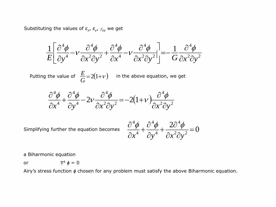
Substituting the values of εx, εy, xy we get
Putting the value of in the above equation, we get
Simplifying further the equation becomes
a Biharmonic equation
or ∇4 ϕ = 0
Airy’s stress function ϕ chosen for any problem must satisfy the above Biharmonic equation.
22
4
22
4
4
4
22
4
4
411
yxGyxxyxyE
12GE
22
4
22
4
4
4
4
4
122yxyxyx
02
22
4
4
4
4
4
yxyx

εx = 6 + x2 + y2 + x4 + y4
εy = 4 + 3x2 + 3y2 + x4 + y4
xy = 5 + 4xy(x2 + y2 + 2)
= 5 + 4x3y + 4xy3 + 8xy
Example The following strains are given
Determine whether the above strain field is possible. If it is possible determine
displacement components u and v, assuming u = v = 0 at origin.

SECOND DEGREE POLYNOMIAL
Let us consider an Airy’s stress function
∇4 ϕ = 0 satisfies the compatibility condition
stress in x direction
stress in y direction
Shear stress,
(negative, tends to rotate the body in counterclockwise
direction). This represents a plane stress condition as
shown in Figure 6.
Figure 6 Plane stress condition
Ax
y
2
2s
22
22y
CBxyx
A
Cy
x
2
2s
Byxxy
t
2
02
22
4
4
4
4
4
yxyx
compatibility condition

Example
Airy’s stress function ϕ = 40 x2−30 xy + 60 y2 satisfies the compatibility
condition ∇4 ϕ = 0. Determine stresses σx, σy and txy, show graphically the stress
distribution. Stresses are in MPa.

A BEAM SUBJECTED TO PURE BENDING
A beam of depth d is subjected to pure bending moment M and no shear force, as shown in Figure
7. Airy’s stress function can be a third degree polynomial:
Figure 7 Beam subjected to pure bending
∇4 ϕ = 0, for this function
Taking B = 0 as stress σx is independent of x, σx = Ay
y varies from − to + as shown (Figure 8).
Figure 8 Stress distributions
Maxm. σx in tension
where
x
y 3223
6226x
Dyx
Cxy
By
A
002
2
BxAy
yx
s
2d
At s
2d
IM
IM
A

Maxm.σxx in compression
where M = bending moment M, and
I = second moment of area (of cross section of beam) about the neutral axis.
Now
but σy = 0, so constant C = D = 0
Shear stress
but
also because it is a case of pure bending.
So, constants B = C = 0
Finally Airy’s stress function is
.
22d
IMd
Ac s
DxCyx
y
2
2s
CxByyxxy
t
2
0xyt
3
6y
A

Example A bar of circular section of diameter 30 mm is subjected to a pure bending moment of 3 × 10⁵ Nmm. What is the maximum bending stress developed in the beam? What is Airy’s stress function for this case?

Example 2.2 For a beam of rectangular section B = 20 mm, D = 30 mm, Airy’s stress function ϕ = 1.6 y3.
Determine the magnitude of constant bending moment acting on beam section.

Example A beam of rectangular section is subjected to shear force F = 1 kN and bending moment = −1 × 10⁶ Nmm. Section of beam is B = 20 mm, D = 60 mm. Write down the stress tensor for an element located at 15 mm below the top surface .
M = −1 × 10⁶ Nmm (producing convexity)
I = second moment of area about neutral plane
y = 15 mm from neutral axis. Bending stress,
4433
103612
602012
mmBD
I
2
4
6
/66.41151036
101mmNy
IM
x
s

To determine shear stress at y = 15 mm from neutral layer
where area a = 15 × 20 = 300 mm2 = area of section above the layer under consideration,
ӯ = 22.5 mm distance of CG of area a from neutral layer,
b = breadth = 20 mm,
I = 36 × 104 mm4,
F = 1 kN = 1000 N,
txy
=
= 0.9375 N/mm2.
Stress tensor for this state of stress, at a layer 15 mm below top surface
Ib
yFaxy t
201036
5.2230010004
MPa09375.0
9375.066.41

Example A cantilever beam of rectangular section B × D and of length L carries a
concentrated load W at free end. Consider a section at a distance x from fixed end and a layer at a distance y from neutral layer zz; derive expression for Airy’s stress functions, if B=40 mm, D=60 mm, W=1 kN,
x=2 m, L=5 m. Write the stress tensor for the layer bc, if y = 20 mm.

Stresses
Let us assume Airy’s stress function ϕ = C1y3 + C2 xy3 + C3 xy.
Boundary conditions are
For τxy = 0, σyy = 0
, shear force is constant
For x = L, σxx = 0 Everywhere
0
y
xx I
yxLW
s
s
yD
I
W
yD
yD
I
W
yD
yyD
BBI
W
z
z
zxy
42
22
22
2
2
2t
2/
2/
D
D
xy WdyBt
xx I
yMs

Applying these boundary conditions
everywhere ϕ satisfies this condition
So, or
02
2
xy
s
2
3
2
2
2
2
30 DyD
yxy CyCyx
or
t
04
3 3
2
2 CD
C2
23 43
DCC
LCC
xyCyCy
Lx
Lx
Lxx
21
212
2
066
s
ϕ = C1y3 + C2 xy3 + C3 xy

Moreover
or
Putting the value of into above equation 2
234
3DCC
DCD
CB
DDC
DDCBW
yCy
CBW
WBdyCyC
WBdyyx
dyB
D
D
D
D
D
D
D
D
xy
3
3
2
3
33
2
2/
2/
3
3
2
2/
2/
3
2
2
2/
2/
22/
2/
4
2288
33
2
t
WBDCD
BC 3
4
2 4
32
33
2
2
2
3
2
2
41
43
43
4
BD
WC
WBDBDC
WBDDCD
BC
ϕ = C1y3 + C2 xy3 + C3 xy

Then
Finally, Airy’s stress function is
At the layer where x = 2000 mm, L = 5000 mm
and
Stress tensor
BDW
BD
WDC
432
43
3
2
3 321
2
BD
WLLCC
xyBDW
xyBD
Wy
BD
WL4322 3
3
3
3
MPa
I
yxLW
mmBD
I
mmy
xx
z
33.831072
2030001000
107212
604012
20
4
4433
s
MPa
yD
I
W
zxy
347.010144
5001000
204
60
10722
1000
42
4
22
4
22
t
MPa0347.0
347.033.83

Example 2.3 A solid circular shaft of steel is transmitting 100 hp at 200 rpm. Determine shaft diameter if the maximum shear stress in shaft is not to exceed 80 MPa. Write down stress tensor for the surface of the shaft. Show that surface of the shaft is under both plane stress and plane strain conditions E = 200 ×
103 N/mm2, = 0.3.
Hint: HP transmitted = 100
Revolutions per minute, N = 200
angular speed,
Torque transmitted,
sradN
/94.2060
2002
60
2
mm 106.3562T
m 6.356294.20746100
3
N
NT

Example 2.4 A cylindrical bar of length L, area of cross section A is fixed at top end. Write down Airy’s stress function for stress due to self weight in bar, if w
is the weight density of the bar.