analysis of superframe duration adjustment scheme for ieee
TRANSCRIPT

Lee et al. EURASIP Journal on Wireless Communicationsand Networking (2015) 2015:103 DOI 10.1186/s13638-015-0296-3
RESEARCH Open Access
Analysis of superframe duration adjustmentscheme for IEEE 802.15.4 networksBih-Hwang Lee1*, Eppy Yundra1, Huai-Kuei Wu2 and M Udin Harun Al Rasyid3
Abstract
The challenge of the IEEE 802.15.4 beacon-enabled mode is how to improve throughput and bandwidth utilizationin contention access period (CAP) and contention free period (CFP), respectively. This article proposes a schemeto improve IEEE 802.15.4 medium access control, called superframe duration adjustment scheme (SUDAS), whichanalyzes the overall of the IEEE 802.15.4 not only CAP but also CFP. SUDAS is expected to effectively allocateguaranteed time slot to the requested devices, it adjusts the length of the slot in superframe duration based onthe length of the packet data. This article also presents a comprehensive Markov chain analysis for SUDAS, especiallyfor star topology, to predict the probability of successful transmission, network goodput, average bandwidthutilization, as well as total network energy consumption. The validity of the analytical model is proven by closelymatching the simulation experiments. SUDAS performs better than other algorithms in terms of the probability ofsuccessful packet transmission, network goodput, average bandwidth utilization, and total energy consumption.
Keywords: IEEE 802.15.4; Markov chain; Guaranteed time slot; Energy consumption
1 IntroductionThe IEEE 802.15.4 standard has been designed to specifythe physical layer (PHY) and medium access control(MAC) sublayer for low power consumption, shorttransmission range, and low-rate wireless personal areanetwork (LR-WPAN) [1]. IEEE 802.15.4 can operate onbeacon- and non-beacon-enabled modes and has threekinds of topologies: star, peer-to-peer, and cluster tree top-ologies. The network coordinator transmits beacon tosynchronize and provide necessary information to the de-vices in beacon enabled-mode, while the unslotted carriersense multiple access with collision avoidance (CSMA/CA) protocol is used in non-beacon-enabled mode. TheIEEE 802.15.4 MAC supports not only contention-basedmechanism in contention access period (CAP) but alsoguaranteed time slot (GTS) in contention free period(CFP) scheme under beacon-enabled-mode. The GTStransmission in CFP can avoid packet drop due to colli-sions in the contention based protocol (i.e., CSMA/CA inCAP). The limited number of allowable retransmissionsand the number of backoffs as specified in the standard
* Correspondence: [email protected] Taiwan University of Science and Technology, 43, Keelung Rd,Section 4, Taipei 106, TaiwanFull list of author information is available at the end of the article
© 2015 Lee et al.; licensee Springer. This is an OAttribution License (http://creativecommons.orin any medium, provided the original work is p
can reduce energy consumption caused by carrier sensing.However, the performance of CAP and CFP are relatedeach other because the number of request GTS packetssuccessfully received by network coordinator may de-crease if the contention level in CAP increases, which willdecrease the throughput of CFP and vice versa. The prob-lem in part of CFP in terms of GTS mechanism is howthe network coordinator allocates time slot duration forthe device nodes which request GTS. However, if the allo-cated GTS slot for device node is inappropriate or lessthan the available bandwidth, the wasted bandwidth willincrease which degrade the performance of network.The performance analysis of IEEE 802.15.4 MAC is one
of the important research topics in wireless sensor net-work. That means research overall performance of theIEEE 802.15.4 MAC includes CAP and CFP simultan-eously still prepossess. The challenge of the IEEE 802.15.4beacon-enabled mode is how to improve throughput andbandwidth utilization in CAP and CFP, respectively. Theauthors of [2] present an evaluation of the slotted CSMA/CA of IEEE 802.15.4 based on all of its frequency, whichonly analyzes each frequency and compares with eachother but not to propose a method. In [3], the authorsanalyze the performance of IEEE 802.15.4 MAC by usingnode state and channel state models that are simple but
pen Access article distributed under the terms of the Creative Commonsg/licenses/by/4.0), which permits unrestricted use, distribution, and reproductionroperly credited.

Lee et al. EURASIP Journal on Wireless Communications and Networking (2015) 2015:103 Page 2 of 17
accurate. The authors also present an analytical model forthe slotted CSMA/CA algorithm adopted in the CAP ofthe beacon-enabled mode in IEEE 802.15.4 MAC, whichonly considers for the saturated mode but not for acknow-ledgement (ACK).Several mathematical analyses based on Markov chain
models have been proposed to analyze the performanceof IEEE 802.15.4, but they do not consider packetretransmissions [4-10]. Some of the modified Markovchain models have been investigated by consideringpacket retransmissions but not considering the defertransmission [11-14]. In [15-18], the authors propose theMarkov chain models with considering the postponetransmission. In [19], the analytical model based onMarkov chain for multi-hop cluster network has beenstudied without considering ACK to confirm the success-ful of data packet transmission. However, all of the above-mentioned models only consider for the contention-basedtransmission, i.e., only for CAP.The authors of [20] propose a methodology to analyze
the GTS mechanism in CFP. In [21], the authorspropose an analytical model based on Markov chain forGTS allocation mechanism in CFP. In [22], the authorsprovide an analysis for channel access during CAP andCFP. However, the purpose of the CFP transmission isto retransmit the packet that is not successful transmit-ted in CAP to cope with hidden node collisions. A num-ber of mechanisms have been proposed to gain effectiveGTS allocation. Multi-beacon superframe (MBS) andgreedy GTS allocation (GGA) algorithms are proposedto decompose a single beacon interval into multiple sub-beacon intervals in order to reduce the bandwidth wasteproblem [23]. However, the increasing number of bea-con transmission in MBS and GGA may increase theenergy consumption. A delay-bound analysis for an im-plicit GTS allocation is proposed to analyze the impacton the bandwidth utilization and delay by using numer-ical network calculus analysis [24]. The authors of [25]analyze the priorities of devices to determine for GTSallocation, while the authors of [26] further proposean adaptive GTS allocation scheme (AGA) using twophases to assign the priorities of devices and scheduleGTS. In [27], the authors propose a method for GTS al-location with improved bandwidth utilization, known asa new GTS allocation scheme with bandwidth utilization(ANBU), which allows more devices to share the band-width within the same period. However, CFP is always di-vided into 16 equal-length slots without considering thevalue of superframe order (SO) and the arrival rate of datapackets; therefore the length of each slot increases if theSO value increases, which causes waste bandwidth. In[28], the authors propose an optimization-based GTS allo-cation scheme designed according to the priorities of thedevices and knapsack problem. The network coordinator
collects the bandwidth requests from devices, then allo-cates GTS to the demanded devices by using fractionalknapsack problem given by their priorities. In [29], the au-thors present a new GTS allocation scheme (NGAS) forIEEE 802.15.4, which divides the CFP into 32 equal-sizedslots. NGAS did not consider the value of SO and the ar-rival rate of data packets, so that it may cause inefficientbandwidth if the value of SO or arrival rate increases. Theauthors of [30] propose a dynamic CFP allocation and op-portunity contention-based protocol to request CFP slotsfor devices in wireless body area network (WBAN) envir-onment. The length of CFP allocation period may increaseas the number of requested CFP slots increases, but thelength of CAP used by the devices will be decreased.However, all of the aforementioned models only considerGTS transmission, i.e., only for CFP. In other words, theydid not consider the overall performance for both CAPand CFP.This article proposes a superframe duration adjust-
ment scheme (SUDAS) for IEEE 802.15.4 which is theextended work from [18] and [31]. In [18], the authorsfocus on how to decrease the collisions between beaconsor even between beacon and data packets by adjustingthe beacon starting times of PAN and coordinator nodesfor cluster tree topology, which only considers for the partof CAP but not for GTS slot allocation in the correspond-ing Markov chain model. SUDAS focuses on assigningadjustable length of GTS slot based on the length ofpacket and also deciding the precise time for the GTSstarting time (GTSstart) and the GTS length (GTSlength)for star topology. SUDAS is expected to effectively allocateGTS to the requested device nodes to improve bandwidthutilization in CFP, while the length of CAP can be used byother device nodes to transmit their data packets whichdo not receive the allocated GTS. The performance ofSUDAS for star topology is analyzed by the Markov chainmodel modified from [18] for considering packet retrans-mission, ACK, defer transmission and GTS allocation,which is to obtain the probability of success transmissions,network goodput, energy consumption, and average band-width utilization for IEEE 802.15.4 MAC.
2 Overview of IEEE 802.15.4The IEEE 802.15.4 standard can operate in beacon-enabled mode and non-beacon-enabled mode. In beacon-enabled mode, each node employs two system parameters:beacon order (BO) and SO. The parameter BO decidesthe length of beacon interval (BI), where BI = aBaseSuper-frameDuration × 2BO symbols and 0 ≤ BO ≤ 14; while theparameter SO decides the length of superframe duration(SD), where SD = aBaseSuperframeDuration × 2SO sym-bols and 0 ≤ SO ≤ BO ≤ 14. The value of aBaseSuperframe-Duration is fixed to 960 symbols. The format of thesuperframe is defined by the network coordinator as

Lee et al. EURASIP Journal on Wireless Communications and Networking (2015) 2015:103 Page 3 of 17
shown in Figure 1. Furthermore, the active portion of eachsuperframe consists of three parts: beacon, CAP, and CFP,which is divided into 16 equal length slots. The length ofone slot is equal to aBaseSlotDuration × 2SO symbols,where aBaseSlotDuration is equal to 60 symbols.In CAP, each node performs the CSMA/CA algorithm
before transmitting data packet or control frame. Eachnode maintains three parameters: the number of back-offs (NB), contention window (CW), and backoff expo-nent (BE). The initial values of NB, CW, and BE areequal to 0, 2, and macMinBE, respectively, where mac-MinBE is equal to 3. In the located boundary of the nextbackoff period, a node takes delay for random backoffbetween 0 and 2BE -1 (2BE minus 1) unit backoff period(UBP), where UBP is equal to 20 symbols (or 80 bits). Anode performs clear channel assessment (CCA) to makesure whether the channel is idle or busy, when the num-ber of random backoff periods is decreased to 0. Thevalue of CW will be decreased by one if the channel isidle; and the second CCA will be performed if the valueof CW is not equal to 0. If the value of CW is equal to0, it means that the channel is idle after twice CCA; thena node is committed the data transmission. However, ifthe CCA is busy, the value of CW will be reset to 2; thevalue of NB is increased by 1; and the value of BE is in-creased by 1 up to the maximum BE (macMaxBE),where the value macMaxBE is equal to 5. The node willrepeatedly take random delay if the value of NB is lessthan the value of macMaxCSMABackoff, where thevalue of macMaxCSMABackoff is equal to 4; and thetransmission attempt fails if the value of NB is greaterthan the value of macMaxCSMABackoff.On the other hand, to transmit packet in CFP, a node
has to request the usage of GTS by sending GTS requestpacket to network coordinator in the CAP of the previ-ous superframe. The network coordinator allocates GTSto the device node if it successfully receives the requestpacket, then the device node transmits its packets byusing the allocated GTS without contention.
3 The description of SUDASA star topology consists of one network coordinator andseveral device nodes, while the network coordinatorperiodically sends beacon frames to the device nodes.The network coordinator allocates the dedicated slots
Figure 1 An example of superframe structure.
for its device nodes, if it receives the requests for GTSpackets in the CAP period, otherwise, the device nodesshall transmit their packets with contention in CAP.This article proposes a superframe duration adjustmentscheme (SUDAS), to analyze both CAP and CFP forIEEE 802.15.4 MAC. SUDAS aims to accurately decidethe values of GTS slot based on the length of packet sizeand packet arrival rate. SUDAS mainly improves theprobability of success transmission, network goodput,average bandwidth utilization, and energy consumptionby managing the GTS allocation for the requested devicenodes. SUDAS can be expanded by considering thelength of data packet, the SO value, and packet arrivalrate. According to the IEEE 802.15.4 standard, let us de-note Tsd to be the time of SD as shown in Equation 1,where aBaseSuperframeDuration and Rs are the mini-mum duration of a superframe and data symbol ratewith the values of 960 symbols and 62,500 symbol/s, re-spectively. Let us also denote Tslot as the time of one slotduration, which can be obtained by Equation 2.
T sd ¼ aBaseSuperframeDuration � 2SO
Rsin seconds½ �
ð1Þ
T slot ¼ T sd
16in seconds½ � ð2Þ
Each device node with an allocated GTS ensures thatthe data transmission time, waiting time for ACK, timeto transmit ACK packet, and interframe spacing (IFS)duration can be completed before the end of its GTSperiod. Let us denote Tf be the time to transmit one datapacket and receive ACK packet, which can be obtainedby Equation 3, where Tdata, TLack, Tack, and TLIFS are thetime to transmit data packet, time to waiting for ACKpacket, time to transmit ACK packet, and time durationof IFS, respectively. The length of Lack is equal to 88 bits,whereas the length of LIFS is equal to macMinLIFSPeriod(160 bits) if the length of packet is greater than aMax-SIFSFrameSize (144 bits), otherwise, it is equal to mac-MinSIFSPeriod (48 bits).
T f ¼ Tdata þ TLack þ T ack þ TLIFS ð3ÞThere are two types of packets, time-critical and non-
time-critical packets, to be transmitted from nodes tothe coordinator. In CAP, the packet transmission delaycannot be guaranteed, because packets are transmittedby using the CSMA/CA algorithm. Conversely, thepacket transmission delay can be guaranteed in CFP,because packets are transmitted by using the allocatedGTS without contention. In this article, we assume thateach node generates time-critical and non-time-criticalpackets with probabilities P and (1 − P), respectively. Letus denote Txn be the time to transmit a data packet

Lee et al. EURASIP Journal on Wireless Communications and Networking (2015) 2015:103 Page 4 of 17
according to its arrival rate by device n as shown inEquation 4, where λn and NGTS are the arrival rate ofdata packets at device n and the number of nodes to beallocated GTS slots in CFP, respectively.
Txn ¼ λn � T sd � PRb
; n ∈ 1; NGTSð Þ ð4Þ
According to IEEE 802.15.4 standard, the maximumvalue to allocate the GTS slot duration is seven. Let usdenote adjslot be the integer value that will be used asthe adjustment for the Tslot of IEEE 802.15.4 standardbecome new smaller adjustment time of one slot dur-ation. The value adjslot can be calculated by Equation 5.Let us denote Tsudas be the new time of one slot durationin SUDAS, which can be calculated by Equation 6. Letus denote Nsudasslotn be the number of request slotsfor each GTS of SUDAS by device n, which is calculatedby Equation 7. Let us denote NumSuperframeSlot be thenumber of slots in a superframe duration, which is equalto 16 according to IEEE 802.15.4 standard. Let us denoteGTSstarn, and GTSlengthn as the starting time, and thelength of a GTS allocation for device n, which can becalculated by Equations 8 to 9, respectively. Let us alsodenote CAPsudasslot and CAPsudaslength be the number ofCAP slots and the time of CAP period based on SUDAS,which can be obtained by Equations 10 and 11, respect-ively, where Lbeacon is the length of beacon in bits whileTbeacon is the time interval of beacon.
adjslot ¼ ⌊T slot
T f⌋; where ⌊x⌋ is the maximum integer
but less than x:ð5Þ
T sudas ¼ T slot
adjslotð6Þ
Nsudasslotn ¼ ⌈TxnT sudas ⌉; where ⌈x⌉ is the minimum
integer but greater than x:
ð7Þ
GTSstartn ¼ NumSuperframeSlot � T slot−T sudas
�Xni¼1
Nsudassloti ; 1≤n≤NGTS ð8Þ
GTSlengthn ¼ Nsudasslotn � T sudas ð9Þ
CAPsudasslot ¼ NumSuperframeSlot−XNGTS
n¼1
Nsudasslotnadjslot
" #ð10Þ
CAPsudaslength ¼ NumSuperframeSlot� T slot−Tbeacon − T sudas
�XNGTS
n¼1
Nsudasslotn ð11Þ
For more details about the aforementioned descrip-tion, we can explain SUDAS with flowchart as shown inFigure 2. We consider a star topology network havingone network coordinator and several device nodes withthe same value of six for SO and BO. By using Equation5, we get the value of adjslot to be 16. Based on the IEEE802.15.4 standard, if each node sends to request one slotGTS in IEEE 802.15.4, and its request successfully re-ceived by network coordinator, thus the number of slotsneeded for CFP is seven as shown in Figure 3. InSUDAS, the number of slots needed for CFP is not morethan one in the 15th slot. Furthermore, if there are morethan seven device nodes in the star topology, the devicenodes which are not allocated GTS can transmits theirdata packets more in CAP period because the CAP dur-ation of SUDAS (CAPsudaslength) is increased as shown inFigure 4. By using SUDAS, the CFP period in super-frame duration effectively increases the average band-width utilization. On the other hand, the device nodeswhich are not getting GTS allocation can increase theirdata packets transmitted in CAP because the CAP dur-ation is increased.
4 Analysis of SUDASIn this section, the proposed SUDAS based on the IEEE802.15.4 MAC use slotted carrier sense multiple access withcollision avoidance (CSMA/CA) for part of CAP and GTStransmission for part of CFP. This article also taking intoaccount the case of acknowledged uplink data transmissioninvestigated comprehensively via Markov chain model asshown in Figure 5. Let bi,j,k be the stationary probability atthe stochastic state (s(t) = i, c(t) = j, and r(t) = k), where s(t),c(t), and r(t) represent backoff stage, backoff counter, andnumber of retransmissions, respectively, shown asEquation 12, where bi,-1,k, bi,-2,k and bi,-3,k are the sta-tionary probabilities for the first CCA (CCA1), thesecond CCA (CCA2), and packet transmission, respect-ively, at the ith backoff stage and the kth retransmission.Let bSi,k and bCi,k be the stationary probabilities of thesuccessful transmission and collision at the states of Si,kand Ci,k as shown in Equations 13 and 14, respectively,where m and R are the maximum NB stage and retrans-missions, i.e., they are equal to 4 and 3, respectively. LetbSGi,k and bDi,k be the stationary probabilities of the suc-cessful request for GTS packets and deferred transmis-sion at the states of SGi,k and Di,k for the ith backoff

Figure 2 The flowchart of SUDAS.
Lee et al. EURASIP Journal on Wireless Communications and Networking (2015) 2015:103 Page 5 of 17
stage and the kth retransmission as shown in Equations15 and 16, respectively.
bi;j;k ¼ limt→∞
P s tð Þ ¼ i; c tð Þ ¼ j; r tð Þ ¼ kf g; for i∈ 0;mð Þ;
j∈ −3; wi−1ð Þ; k∈ 0; Rð Þð12Þ
bSi;k ¼ limt→∞
P Ss tð Þ ¼ Si; r tð Þ ¼ k� �
; i∈ 0; mð Þ; k∈ 0; Rð Þð13Þ
bCi;k ¼ limt→∞
P Cs tð Þ ¼ Ci; r tð Þ ¼ k� �
; i∈ 0; mð Þ; k∈ 0; Rð Þð14Þ
bSGi;k ¼ limt→∞
P SGs tð Þ ¼ SGi; r tð Þ ¼ k� �
; i∈ 0; mð Þ; k∈ 0; Rð Þ
ð15Þ
bDi;k ¼ limt→∞
P Ds tð Þ ¼ Di; r tð Þ ¼ k� �
; i∈ 0; mð Þ; k∈ 0; Rð Þð16Þ
Figure 3 An example of GTS allocation in IEEE 802.15.4.
Let us explain the parameters used in the Markovchain model as follows. Let wi ¼ 2BEi be the backoff win-dow at the ith backoff stage of a device, where the back-off exponent BEi = 3, 4, 5, 5, and 5 for 0 ≤ i ≤m. AnIDLE state means that a device node has no packet totransmit. Let us denote q be the probability that a packetarrives at a node during the active period.The MAC sublayer should transmit its packet if the
remaining CSMA/CA steps, i.e., CCA analyses, theframe transmission, and any ACK can be completed be-fore the end of CAPsudaslength. Conversely, if the currentCAPsudaslength has not enough slots to transmit datapackets, it should defer transmission until the beginningof the CAPsudaslength in the next superframe duration.Let d be the probability of defer transmission that noenough slot is left in the current CAPsudaslength to trans-mit data packet, which can be obtained by Equation 17,where TtxCCA is the time to transmit CCA.
d ¼ 2TtxCCA þ Tf
CAPsudaslengthð17Þ
Let us denote α and β be the probabilities that CCA1
and CCA2 are busy, respectively. CCA1 busy means thatthe device node at one of the CCA1 states while at leastone of the other nodes at packet transmission state,while CCA2 busy means that the device node at one ofthe CCA2 states while at least one of the other nodes atpacket transmission state. Let us also denote Pcoll to bethe probability of the collision of packet transmission

Figure 4 An example of GTS allocation in SUDAS.
Figure 5 Markov chain model for SUDAS.
Lee et al. EURASIP Journal on Wireless Communications and Networking (2015) 2015:103 Page 6 of 17

Lee et al. EURASIP Journal on Wireless Communications and Networking (2015) 2015:103 Page 7 of 17
after CCA2, i.e., the device node at packet transmissionstate while at least one of the other nodes in the packettransmission state at the same time. Let us also denote Pfail1and Pfail2 to be the probabilities of fail transmission due tothe maximum number of retransmissions after collisionsand no channel to use after reaching the maximum backoffstage at the maximum retransmission stage, respectively.To analyze the Markov chain model, several state transi-
tion probabilities are evaluated as shown from Equations18 to 26. Equation 18 states the probability that the back-off counter is decreased after each slot. Equation 19 givesthe probability of finding busy channel either in CCA1
and CCA2. Equation 20 states the probability of picking abackoff state in the next retransmission stage after the col-lision of packet transmission when having enough time tosend packet in the remaining active period and channelidle in both CCA1 and CCA2. Equation 21 states the prob-ability of entering the IDLE state after the collision ofpacket transmission while reaching the maximum retrans-mission stage after finding the remaining active period tobe enough to send packet and channel idle in both CCA1
and CCA2. Equation 22 states the probability that theremaining CAP is not enough to send packet and need todefer and then pick the backoff state in the next super-frame. Equation 23 states the probability of successfulpacket transmission and picking new random backoff atthe first backoff stage. Equation 24 states the probabilityof entering the IDLE state if the node has no data packetto transmit after successful packet transmission. Equation25 states the probability of entering the IDLE state due tochannel access failure. Equation 26 states the probabilityof going to the first backoff stage from the IDLE state ifthe node has data packet to transmit.
P i; j; kji; jþ 1; kð Þ ¼ 1; i∈ 0; mð Þ; j∈ 0; wi−2ð Þ; k∈ 0; Rð Þð18Þ
P i; j; k j i−1; 0; kð Þ ¼ wi−jwi
1−dð Þ αð Þ þ 1−dð Þ 1−αð Þβ
¼ wi−jwi
1−dð Þ αþ 1−αð Þβ½ �;
i∈ 1; mð Þ; j∈ 0; wi−1ð Þ; k∈ 0; Rð Þð19Þ
P 0; 0; kji; 0; k−1ð Þ ¼ 1−dð Þ 1−αð Þ 1−βð Þ Pcollð Þ; k∈ 1; Rð Þð20Þ
P IDLEji; 0; Rð Þ ¼ 1−dð Þ 1−αð Þ 1−βð Þ Pcollð Þ 1−qð Þ ð21Þ
P 0; j; kji; 0; kð Þ ¼w0−jw0
dð Þ 1−PGTSð Þ q; for k ¼ 0
w0−jw0
dð Þ 1−PGTSð Þ; for k ∈ 1; Rð Þ
8><>:
ð22Þ
P 0; j; 0ji; 0; kð Þ ¼ w0−jw0
1−dð Þ 1−αð Þ 1−βð Þ 1−Pcollð Þ q;
i∈ 0; mð Þ; j∈ 0; wi−1ð Þ; k∈ 0; Rð Þð23Þ
P IDLEji; 0; kð Þ ¼ 1−dð Þ 1−αð Þ 1−βð Þ 1−Pcollð Þ 1−qð Þ;
i∈ 0; mð Þ; k∈ 0; Rð Þð24Þ
P IDLEjm; 0; Rð Þ ¼ 1−dð Þ αþ 1−αð Þ βð Þ½ � 1−qð Þ ð25Þ
P 0; j; 0jIDLEð Þ ¼ w0−jw0
q; j∈ 0; wi−1ð Þ ð26Þ
By using Equation 19, the stationary probability bi,j,k canbe obtained by Equation 27. From Equation 20, b0,0,k canbe obtained by Equation 28, where Y and X are the prob-abilities of entering the next backoff stage and the collisionof packet transmission in a certain backoff stage, respect-ively. Similarly, bi,0,k can be obtained by Equation 29. Fi-nally, the steady-state probabilities to perform randombackoff (Prandb), CCA1 (PCCA1), CCA2 (PCCA2), packettransmission (Ppt), successful packet transmission(Psuc), collision of packet transmission (Pcopt), deferredtransmission (Pdtx), successful request for GTS packet(Psg), and idle state (Pidle) can be obtained from Equa-tions 30 to 38, respectively, where PGTS is the probabil-ity of requesting GTS allocation. Since the sum ofprobabilities in the Markov chain must be equal to one,we have Equation 39. By using Equations 30 to 39, wecan get the value of b0,0,0 easily by using excelspreadsheet.
bi;j;k ¼ wi−jwi
bi−1;0;k 1−dð Þ αþ 1−αð Þβ½ � ¼ wi−jwi
bi;0;k ð27Þ
b0;0;k ¼ 1−dð Þ 1−αð Þ 1−βð ÞPcoll
Xmi¼0
bi;0;k−1
þ 1−dð Þ αþ 1−αð Þβ½ � bm;0;k−1
¼ 1−dð Þ 1−αð Þ 1−βð ÞPcoll
Xmi¼0
bi;0;k−1 þ Y bm;0;k−1
¼ b0;0;0 1−dð Þ 1−αð Þ 1−βð ÞPcoll
Xmi¼0
Y i
!k
þ Ymþ1� �k2
435
¼ b0;0;0 1−dð Þ 1−αð Þ 1−βð ÞPcoll
Xmi¼0
Y i
!k
þ Ymþ1� �k2
435
¼ b0;0;0 1−dð Þ 1−αð Þ 1−βð ÞPcollUð Þk þ Zkh i
¼ b0;0;0 Xk þ Zk� �
ð28Þ

Lee et al. EURASIP Journal on Wireless Communications and Networking (2015) 2015:103 Page 8 of 17
where Y = (1 − d)[a + (1 − a)b]; Z = Ym + 1; U ¼ 1−Z1−Y
� �;
and X = (1 − d)(1 − a)(1 − b)PcollU for simplicity.
bi;0;k ¼ bi−1;0;k 1−dð Þ αþ 1−αð Þβ½ � ¼ 1−dð Þ αþ 1−αð Þβ½ �ð Þi b0;0;k¼ Y i b0;0;k ¼ Y ib0;0;0 Xk þ Zk
� �for i∈ 0;mð Þ; k∈ 0;Rð Þ
ð29Þ
Prandb = P (perform random backoff ):
¼Xmi¼0
Xwi−1
j¼0
XRk¼0
bi;j;k
¼Xmi¼0
XRk¼0
wi
21−dð Þ αþ 1−αð Þβ½ �ð Þib0;0;k
¼Xmi¼0
XRk¼0
wi
2Y ib0;0;k
¼ w0
2b0;0;0
1− X þ Zð ÞR1− X þ Zð Þ −2XZ
!1− 2Yð ÞR1− 2Yð Þ þ 4Y 3 þ 4Y 4
" #
¼ w0
2b0;0;0 V Q
ð30Þ
where V ¼ 1− XþZð ÞR1− XþZð Þ −2XZ and Q ¼ 1− 2Yð ÞR
1− 2Yð Þ þ 4Y 3 þ 4Y 4
for simplicity.PCCA1 = P (perform the first clear channel assessment):
¼Xmi¼0
XRk¼0
bi;−1;k ¼ 1−dð ÞXmi¼0
XRk¼0
1−dð Þ αþ 1−αð Þβ½ �ð Þib0;0;k
¼ 1−dð Þ 1−αð ÞXmi¼0
XRk¼0
Y ib0;0;k
¼ b0;0;01− X þ Zð ÞR1− X þ Zð Þ −2XZ
!1−Z1−Y
� �1−dð Þ
¼ b0;0;0 V U 1−dð Þð31Þ
PCCA2 = P (perform the second clear channel assessment):
¼Xmi¼0
XRk¼0
bi;−2;k ¼ 1−dð Þ 1−αð ÞXmi¼0
XRk¼0
1−dð Þ αþ 1−αð Þβ½ �ð Þib0;0;k
¼ 1−dð Þ 1−αð ÞXmi¼0
XRk¼0
Y ib0;0;k
¼ b0;0;01− X þ Zð ÞR1− X þ Zð Þ −2XZ
!1−Z1−Y
� �1−dð Þ 1−αð Þ
¼ b0;0;0 V U 1−dð Þ 1−αð Þð32Þ
Ppt = P (packet transmissions):
¼Xmi¼0
XRk¼0
bi;−3;k ¼ 1−dð Þ 1−αð Þ 1−βð ÞXmi¼0
XRk¼0
Y ib0;0;k
¼ b0;0;01− X þ Zð ÞR1− X þ Zð Þ −2XZ
!1−Z1−Y
� �1−dð Þ 1−αð Þ 1−βð Þ
¼ b0;0;0V U 1−dð Þ 1−αð Þ 1−βð Þð33Þ
Psuc = P (successful packet transmissions):
¼Xmi¼0
XRk¼0
bSi;k ¼ 1−dð Þ 1−αð Þ 1−βð Þ 1−Pcollð ÞXmi¼0
XRk¼0
Y ib0;0;k
¼ b0;0;01− X þ Zð ÞR1− X þ Zð Þ −2XZ
!1−Z1−Y
� �1−dð Þ 1−αð Þ 1−βð Þ 1−Pcollð Þ
¼ b0;0;0V U 1−dð Þ 1−αð Þ 1−βð Þ 1−Pcollð Þð34Þ
Pcopt = P (collided packet transmissions):
¼Xmi¼0
XRk¼0
bCi;k ¼ 1−dð Þ 1−αð Þ 1−βð ÞPcoll
Xmi¼0
XRk¼0
Y ib0;0;k
¼ b0;0;0 X1− X þ Zð ÞR1− X þ Zð Þ −2XZ
!¼ b0;0;0 X V
ð35Þ
Pdtx = P (deferred transmission):
¼Xmi¼0
XRk¼0
bDi;k ¼ dXmi¼0
XRk¼0
1−dð Þ αþ 1−dð Þ 1−αð Þβð Þib0;0;k
¼ dXmi¼0
XRk¼0
1−dð Þ αþ 1−αð Þβð Þð Þib0;0;k ¼ dXmi¼0
XRk¼0
Y ib0;0;k
¼ b0;0;0 d1− X þ Zð ÞR1− X þ Zð Þ −2XZ
!1− Z1−Y
� �¼ b0;0;0 d V U
ð36ÞPsg = P (successful request for GTS packets):
Lee et al. EURASIP Journal on Wireless Communications and Networking (2015) 2015:103 Page 9 of 17
¼Xmi¼0
XRk¼0
bSGi;k ¼ d PGTS
Xmi¼0
XRk¼0
1−dð Þ αþ 1−αð Þβð Þð Þib0;0;k
¼ d PGTS
Xmi¼0
XRk ¼0
Y i b0;0;k
¼ b0;0;0 d PGTS1− X þ Zð ÞR1− X þ Zð Þ −2XZ
!1− Z1−Y
� �
¼ b0;0;0 d PGTS V U
ð37Þ
Pidle ¼ 1−qð ÞXmi¼0
XRk¼0
bSi;k þ 1−qð ÞXmi¼0
XRk¼0
bSGi;k þ 1−qð ÞXmi¼0
bCi; R þ d 1−qð Þ 1−PGTSð ÞXmi¼0
bi;0;0
þ 1−qð Þ 1−dð Þ αþ 1−αð Þβ½ �ð Þ bm;0;R þ 1−qð Þ Pidle
Pidle ¼ 1−qð Þq
Xmi¼0
XRk¼0
bSi;k þXmi¼0
XRk¼0
bSGi;k þXmi¼0
bCi;R þ d 1−PGTSð ÞXmi¼0
bi;0;0 þ Y bm;0;R
" #
¼ 1−qð Þq
b0;0;0
1− X þ Zð ÞR1− X þ Zð Þ −2XZ
!1− Yð Þmþ1
1− Yð Þ
!1−dð Þ 1−αð Þ 1−βð Þ 1−Pcollð Þ þ
1− X þ Zð ÞR1− X þ Zð Þ −2XZ
!1− Yð Þmþ1
1− Yð Þ
!d PGTS þ
X2 þ Z2� �
1−dð Þ 1−αð Þ 1−βð Þ Pcoll1−Ymþ1
1−Y
� �þ
d 1−PGTSð Þ 1−Ymþ1
1−Y
� �þ Ymþ1 X2 þ Z2
� �
266666666666664
377777777777775
¼ 1−qð Þq
b0;0;0V U 1−dð Þ 1−αð Þ 1−βð Þ 1−Pcollð Þ þ V U d PGTS
þ X2 þ Z2� �
X þ d 1−PGTSð Þ U þ Z X2 þ Z2� ��
¼ 1−qð Þq
b0;0;0V U 1−dð Þ 1−αð Þ 1−βð Þ 1−Pcollð Þ þ d PGTS½ �þ X2 þ Z2� �
X þ Zð Þ þ d 1−PGTSð Þ U�
ð38Þ
Xmi¼0
Xwi−1
j¼0
XRk¼0
bi;j;k þXmi¼0
XRk¼0
bi;−1;k þXmi¼0
XRk¼0
bi;−2;k
þXmi¼0
XRk¼0
bi;−3;k þXmi¼0
XRk¼0
bSi;k
þXmi¼0
XRk¼0
bCi;k þXmi¼0
XRk¼0
bDi; k
þXmi¼0
XRk¼0
bSGi;k þPidle ¼ 1
ð39Þ
Let ϕ1 and ϕ2 be the conditional probabilities that atagged node will be at one of the CCA1 states afterbackoff and at one of the CCA2 states after sensingchannel idle in the CCA1, which can be obtained byEquations 40 and 41, respectively. Let us denote τ be the
probability that a device node can transmit a packet,i.e., the device node is in one of the CCA1 states andsenses the CCA2 is idle, while the other nodes arenot in the CCA1 state, which can be calculated byEquation 42. Let us denote NGTS and NWGTS as thenumber of nodes to be and not to be allocated GTSslots, respectively.Since α is the probability of the CCA1 busy, we can also
consider with the transmission of the data packets and GTSrequest packets. Let αdata and αrequest be the probabilitiesthat CCA1 is busy for sending data packets and GTS re-quest packets, which can be obtained by Equations 43 and44, respectively. Similarly, let βdata and βrequest be the prob-abilities that CCA2 is busy for sending data packets andGTS request packets, which can be obtained by Equations45 and 46, respectively. Therefore, α and β can be obtainedby Equations 47 and 48, respectively. Finally, the previousmentioned probabilities of Pcoll, Pfail1, and Pfail2 can beexpressed by Equations 49 to 51, respectively.

φ1 ¼
Xmi¼0
XRk¼0
bi;−1;k
Xmi¼0
XRk¼0
bi;−1;k þXmi¼0
Xwi−1
j¼0
XRk¼0
bi;j;k
¼
1− X þ Zð ÞRþ1
1− X þ Zð Þ −2XZ
!1−Z1−Y
� �1−dð Þ
1− X þ Zð ÞRþ1
1− X þ Zð Þ −2XZ
!1−Z1−Y
� �1−dð Þ þ w0
21− 2Yð ÞRþ1
1− 2Yð Þ þ 4Y 3 þ 4Y 4
!" #
¼ V 0 U 1−dð ÞV 0 U 1−dð Þ þ w0
2Q0
h i
ð40Þ
Lee et al. EURASIP Journal on Wireless Communications and Networking (2015) 2015:103 Page 10 of 17
where V 0 ¼ 1− XþZð ÞRþ1
1− XþZð Þ −2XZ and Q0 ¼ 1− 2Yð ÞRþ1
1−2Y þ 4Y 3 þ 4
Y 4 for simplicity.
φ2 ¼
Xmi¼0
XRk¼0
bi;−2;k
Xmi¼0
XRk¼0
bi;−1;k þXmi¼0
XRk¼0
bi;−2;k þXmi¼0
Xwi−1
j¼0
XRk¼0
bi;j;k
¼
1− X þ Zð ÞRþ1
1− X þ Zð Þ −2XZ
!1−Z1−Y
� �1−dð Þ 1−αð Þ
1− X þ Zð ÞRþ1
1− X þ Zð Þ −2XZ
!1−Z1−Y
� �1−dð Þ 2−αð Þ þ w0
21− 2Yð ÞRþ1
1−2Yþ 4Y 3 þ 4Y 4
! !" #
¼ V 0U 1−dð Þ 1−αð ÞV 0 U 1−dð Þ 2−αð Þ þ w0
2Q0
h i
ð41Þ
τ ¼ φ1 1−φ1ð ÞNWGTS−1 1−αð Þ 1−βð Þ ð42Þ
αdata ¼ 1−Pð Þ φ1 1− 1−τð Þ NWGTS−1ð Þ �
ð43Þ
αrequest ¼ P φ1 1− 1−τð Þ NWGTS−1ð Þ �
ð44Þ
βdata ¼ 1−Pð Þ φ2 1− 1−τð Þ NWGTS−1ð Þ �
ð45Þ
βrequest ¼ P φ2 1− 1−τð Þ NWGTS−1ð Þ �
ð46Þ
α ¼ αdata þ αrequest ¼ φ1 1− 1−τð Þ NWGTS−1ð Þ �
ð47Þ
β ¼ βdata þ βrequest ¼ φ2 1− 1−τð Þ NWGTS−1ð Þ �
ð48Þ
Pcoll ¼ NWGTS τ 1− 1−τð Þ NWGTS−1ð Þ �
ð49Þ
Pfail1 ¼Xmi¼0
bCi;R ¼ b0;0;0 XR þ ZR� �
X ð50Þ
Pfail2 ¼ bm;0;R 1−dð Þ α þ 1−αð Þβð Þ
¼ b0;0;0 Ym XR þ ZR� �
1−dð Þ α þ 1−αð Þβð Þð51Þ
Let denote Pcr to be the probability of collision trans-mission after j attempts (probability of packet beingdropped due to collision retransmission), which can becalculated by Equation 52. Let PdropWGTS and PsucWGTS
be the probabilities of non-GTS packets beingdropped and successful transmission from devicenode to its coordinator, which can be obtained by

Lee et al. EURASIP Journal on Wireless Communications and Networking (2015) 2015:103 Page 11 of 17
Equations 53 and 54, respectively. Let us also denoteNWGTSrecvcoord and Tsim to be the number of non-GTS packets received by the network coordinator andtime of simulation, which can be calculated by Equation55. Therefore, the goodput of SUDAS CAP in thenetwork, denoted by SCAPsudaslength, can be calculatedby Equation 56.
Pcr ¼XRk¼1
Pcollð Þk ð52Þ
PdropWGTS ¼ Pcr þ Pfail 1 þ Pfail2 ð53Þ
PsucWGTS ¼ 1 ‐ PdropWGTS ð54Þ
NWGTSrecvcoord ¼ 1−Pð Þ � λn � NWGTS � 1−PdropWGTS� �� T sim
Ldata
ð55Þ
SCAPsudaslength ¼ NWGTSrecvcoord � LdataNbeacon � BIcoord
ð56Þ
Let us denote Rreq and Nreq to be the GTS request rate ofdevice node and the number of packets per request,respectively, then PGTS can be calculated by Equation57. Let Ptsg be the probability of the successful GTStransmission, which can be obtained by Equation 58,where Psg has been done by Equation 37. Let also denoteNGTSrecvcoord and SCFPsudaslength be the number of GTSpackets received by the network coordinator and thegoodput of SUDAS CFP in the network, which canbe calculated by Equations 59 and 60, respectively. Finally,the total goodput in the network, denoted by Stotal, can becalculated by Equation 61.
PGTS ¼ Rreq � N req � TxnT sd
� �ð57Þ
Ptsg ¼ Psg � PGTS þ 1Psg
� �� 1−dð Þ ð58Þ
NGTSrecvcoord ¼ P � λn � NGTS � Ptsg � T sim
Ldatað59Þ
SCFPsudaslength ¼ NGTSrecvcoord � LdataNbeacon � BIcoord
ð60Þ
Stotal ¼ NWGTSrecvcoord þ NGTSrecvcoordð Þ � LdataNbeacon � BIcoord
ð61Þ
Let Nbeacon and Tq be the number of beacons and thetime to transmit one data packet and receive ACK packet inCAPsudaslength, which can be obtained by Equations 62and 63, respectively. Let us also denote bandwidthutilization (BU)CAPsudaslength, BUCFPsudaslength, andBUsudastotal to be the BUs for CAP, CFP, and totalaverage amount in the network, which can be obtained byEquations 64 to 66, respectively.
Nbeacon ¼ T sim
T sdð62Þ
Tq ¼ 2TtxCCA þ Tf ð63Þ
BUCAPsudaslength ¼ NWGTSrecvcoord � Tq
Nbeacon � CAPsudaslengthð64Þ
BUCFPsudaslength ¼ NGTSrecvcoord � Tf
T sudas
XNGTS
n¼1
Nsudasn
!� Nbeacon
ð65Þ
BUsudastotal ¼ BUCAPsudaslength þ BUCFPsudaslength
2ð66Þ
Let TeCAPsudaslength and Ldelay be the estimated remainingCAPsudaslength in time (seconds) and length (bits), whichcan be calculated by Equations 67 to 68, respectively. Let usdenote Edev, Ecoord, and Etotal to be the energy consumptionsby device nodes, coordinator node, and total amount in thestar topology, which can be calculated by Equations69 to 71, respectively, where PWRidle, PWRtx, andPWRrx are the power consumptions for idle, transmit-ting a packet and receiving a packet, respectively; andLCCA, Lbeacon, and Lrequest are the transmission lengths(bits) of CCA, beacon, and GTS request (72 bits),respectively. Let us denote Dnode to be the distancebetween a device node and its coordinator.
T eCAPsudaslength ¼ Pdtx � CAPsudaslength ¼ b0;0;0 � V � U
�d � CAPsudaslength
ð67Þ
Ldelay ¼ T eCAPsudaslength � Rb ð68Þ

Edev ¼ PWRidle
Xmi¼0
Xwi−1
j¼0
XRk¼0
bi;j;k SDCoordT sim
BICoordNWGTSð Þ
!þ
2PWRtx1−Pð Þ λnð Þ
CAPsudaslength
LCCARb
Xmi¼0
XRk¼0
bi;−1;k þ bi;−2;k� �
T sim Dnode NWGTSð Þ !
þ
PWRtx1−Pð Þ λnð Þ
CAPsudaslength
LdataRb
PsucWGTS T sim Dnode NWGTSð Þ� �
þ PWRtxPð Þ λnð Þ
CAPsudaslength
LrequestRb
PGTS T sim Dnode NGTSð Þ� �
þ
PWRtxPð Þ λnð Þ
CFPsudaslength
LdataRb
PGTS T sim Dnode NGTSð Þ� �
þ PWRtx1−Pð Þ λnð Þ
CAPsudaslength
LdelayRb
Pdtx T sim NWGTSð Þ� �
þ
PWRidle Pidle SDCoordT sim
BICoordN totalð Þ
� �þ PWRrx
LbeaconRb
T sim
BIcoordN totalð Þ
� �þ
PWRrx1−Pð Þ λnð Þ
CAPsudaslength
LackRb
PsucWGTS T sim NWGTSð Þ� �
þ PWRrxPð Þ λnð Þ
CFPsudaslength
LackRb
PGTS T sim NGTSð Þ� �
ð69Þ
Lee et al. EURASIP Journal on Wireless Communications and Networking (2015) 2015:103 Page 12 of 17
ECoord ¼ PWRidle Pidle SDCoordT sim
BICoord
� �
þ PWRtxLbeaconRb
T sim
BICoordDnode
� �
þ PWRrx1−Pð Þ λnð Þ
CAPsudaslength
LdataRb
PsucWGTS T sim NWGTS
� �
þ PWRrxPð Þ λnð Þ
CAPsudaslength
LrequestRb
PGTS T sim NGTS
� �
þ PWRrxPð Þ λnð Þ
CFPsudaslength
LdataRb
PGTS T sim NGTS
� �
þ PWRtx1−Pð Þ λnð Þ
CAPsudaslength
LackRb
PsucWGTS T sim Dnode NWGTS
� �
þ PWRtxPð Þ λnð Þ
CFPsudaslength
LackRb
PGTS T sim Dnode NGTS
� �
ð70Þ
Etotal ¼ Edev þ Ecoord ð71Þ
The energy consumption of device node consists often parts as shown in Equation 69. The first part is en-ergy consumption for backoff. The second part is energyconsumption for CCA transmission. The third part isenergy consumption for data packet transmission usingCSMA/CA in CAP. The fourth part is energy consump-tion for request GTS. The fifth part is energy consump-tion for data packet transmission using GTS in CFP.The sixth part is energy consumption for waiting due todeferred transmission. The seventh part is energy con-sumption for idle. The eighth part is energy consump-tion for receiving beacon. The ninth part is energyconsumption for receiving ACK if transmitting packet issuccessful, and the tenth part is energy consumption forACK if transmission packet using GTS is successful.The energy consumption of coordinator node consists
of seven parts as shown in Equation 70. The first part isenergy consumption for idle. The second part is energy
consumption for transmission beacon. The third part isenergy consumption for receiving data at CSMA/CA inCAP. The fourth part is energy consumption for receivingrequest for GTS allocation. The fifth part is energy con-sumption for receiving data at GTS in CFP. The sixth partis energy consumption for transmitting ACK, if receivingpacket successful in CAP. The seventh part is energy con-sumption for transmitting ACK, if receiving packet GTS issuccessful in CFP. Finally, the total energy consumption innetworks consist of the energy consumption by devicesnode and coordinator node as shown in Equation 71.
5 Simulation and analysis resultsIn this section, simulation experiments for SUDAS areperformed by using the extended Castalia simulator tovalidate the analysis and performance evaluation. Theperformance of SUDAS is compared with NGAS,ANBU, and the IEEE 802.15.4 standard, which includethe analytical (ana) and simulation (sim) results. Weconsider a star topology with one PAN coordinator and20 device nodes, where Dnode is equal to 10 m. To simu-late the performance of power consumption, we con-sider the radio parameters of Chipcon’s CC2420 2.4GHz for the IEEE 802.15.4 RF transceiver [32], wherethe transmitting power PWRtx, the receiving powerPWRrx, and the idle power PWRidle are 31.32mW, 35.28mW, and 712 μW, respectively [33]. The BO and SO set-tings follow the IEEE 802.15.4 standard and the pro-posed SUDAS algorithm, which are fixed to be six. Wecompute the probability of successful packet transmis-sion in CAP, network goodput, average bandwidthutilization (BU), and total network energy consumption,where traffic load varies from 0.1 to 1(full loaded).Table 1 summarizes the simulation parameters.Figure 6 shows the probability of successful transmis-
sion arriving at the PAN coordinator against the trafficload by analytical and simulation. In CFP, nodes do not

Table 1 The simulation parameters
Parameter Value
Physical data rate 250 kbps
Packet length (Ldata) 560 bits
UBP 80 bits
NumSuperframeSlots 16
MacPacketOverhead 112 bits
ACK length (Lack) 88 bits
Dnode 10 m
PWRtx 31.32 mW
PWRrx 35.28 mW
PWRidle 712 μW
BO = SO 6
BEmin 3
BEmax 5
Lee et al. EURASIP Journal on Wireless Communications and Networking (2015) 2015:103 Page 13 of 17
compete with each other and each node has the dedi-cated slots, hence we only consider part of CAP in thisarticle. The proposed SUDAS algorithm has higherprobability of successful transmissions than those ofNGAS, ANBU, and IEEE 802.15.4 standard because thelength of CAPsudaslength is longer than those of CAPNGAS,CAPANBU, and CAPstandard, respectively.Figure 7 shows the network goodput against traffic
load. The network goodput obtained by simulation isvery close to that obtained by the analytical model. It isobvious the network goodput of SUDAS is higher thanthose of the other algorithms. In the light traffic load(i.e., traffic load is equal to 0.1 and 0.2), the network
SUDAS (ana)
SUDAS (sim)
Standard (ana)
Standard (sim)
NGAS (ana)
NGAS (sim)
ANBU (ana)
ANBU (sim)Probability
ofsuccessful
transm
issions
0
0.2
0.4
0.6
0.8
1.0
0.1 0.2 0.3 0.4 0.
TraFigure 6 The probability of successful transmission against traffic load.
goodput of SUDAS is almost the same as those of NGAS,ANBU, and IEEE standard; however, SUDAS outperformsthe other algorithms as the traffic load increases. Theaverage goodput of SUDAS increases by 8.30%, 14.23%,and 19.21% compared to NGAS, ANBU, and IEEE 802.15.4standard, respectively.Figure 8 shows the average BU against traffic load.
The average bandwidth utilization of SUDAS has betterefficiency than those of other algorithms. The averagebandwidth utilization of SUDAS increases by 20.41%,33.80%, and 41.65% compared to NGAS, ANBU, and IEEE802.15.4 standard, respectively. SUDAS can improve theaverage bandwidth utilization because the size of slot isadjustable with the data packet to be transmitted, i.e.,SUDAS can reduce the waste of bandwidth.Figure 9 shows the network energy consumption
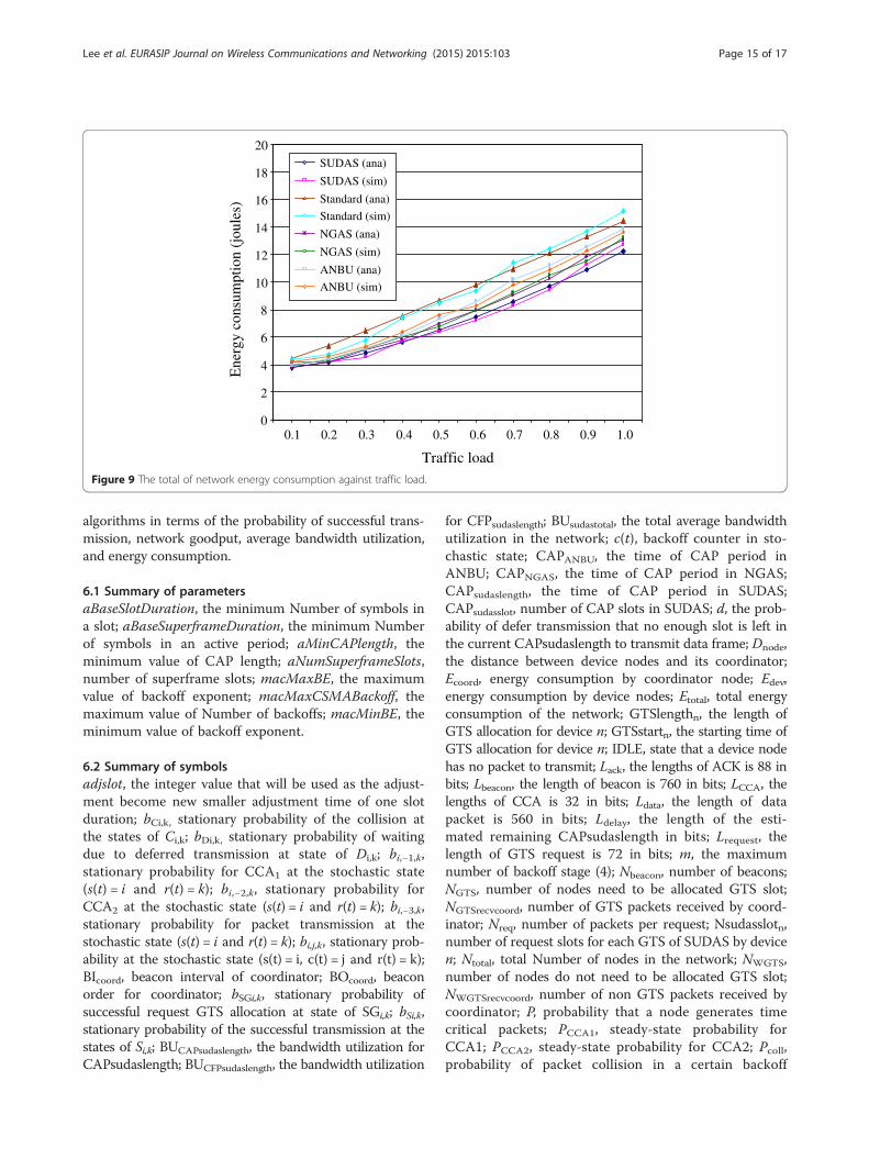
against traffic load. The average energy consumption ofSUDAS reduces by 5.65%, 12.94%, and 26.15% comparedto NGAS, ANBU, and IEEE standard, respectively.SUDAS consumes lesser network energy than those ofother algorithms, because CAPsudaslength is longer thanthose of other algorithms. Moreover, SUDAS has greaterprobability of successful transmission than those ofother algorithms, especially in heavy traffic load, whichmeans that SUDAS minimizes the energy consumptionwhen retransmitting data packet. The energy consump-tion is obtained by summing the energy consumption ofPAN coordinator and all of device nodes in the network.
6 ConclusionsIn this article, SUDAS is proposed to improve the IEEE802.15.4 medium access control, which analyzes not only
5 0.6 0.7 0.8 0.9 1.0
ffic load

Networkgoodput(kbps)
0
20
40
60
80
100
120
0.1 0.2 0.3 0.4 0.5 0.6 0.7 0.8 0.9 1.0
Traffic load
SUDAS (ana)
SUDAS (sim)
Standard (ana)
Standard (sim)
NGAS (ana)
NGAS (sim)
ANBU (ana)
ANBU (sim)
Figure 7 The network goodput against traffic load.
Lee et al. EURASIP Journal on Wireless Communications and Networking (2015) 2015:103 Page 14 of 17
CAP but also CFP. SUDAS performs with the adjust-able length of the slot in the superframe durationbased on the length of data packet, so that it can ac-curately decide for the starting time, and the GTSlength to be allocated for the requested devices to al-leviate the waste of GTS bandwidth utilization.SUDAS is expected to effectively allocate GTS to therequested devices, because the length of CAPsudaslengthis longer than those of other algorithms.
Average
bandwidth
utilizatio
n
0
0.2
0.4
0.6
0.8
1.0
0.1 0.2 0.3 0.4 0.
Tra
SUDAS (ana)
SUDAS (sim)
Standard (ana)
Standard (sim)
NGAS (ana)
NGAS (sim)
ANBU (ana)
ANBU (sim)
Figure 8 The average bandwidth utilization against traffic load.
This paper also presented a comprehensive Markov chainanalysis of IEEE 802.15.4, specifically for star topology, topredict the probability of successful transmission, thenetwork goodput, average bandwidth utilization, aswell as the network energy consumption. The validityof the analytical model is shown by closely matchingits predictions of the simulation results. The analyticalmodel and simulation experiment results show that theperformance of SUDAS is better than those of other
5 0.6 0.7 0.8 0.9 1.0
ffic load
Energyconsum
ption(joules)
0
2
4
6
8
10
12
14
16
18
20
0.1 0.2 0.3 0.4 0.5 0.6 0.7 0.8 0.9 1.0
Traffic load
SUDAS (ana)
SUDAS (sim)
Standard (ana)
Standard (sim)
NGAS (ana)
NGAS (sim)
ANBU (ana)
ANBU (sim)
Figure 9 The total of network energy consumption against traffic load.
Lee et al. EURASIP Journal on Wireless Communications and Networking (2015) 2015:103 Page 15 of 17
algorithms in terms of the probability of successful trans-mission, network goodput, average bandwidth utilization,and energy consumption.
6.1 Summary of parametersaBaseSlotDuration, the minimum Number of symbols ina slot; aBaseSuperframeDuration, the minimum Numberof symbols in an active period; aMinCAPlength, theminimum value of CAP length; aNumSuperframeSlots,number of superframe slots; macMaxBE, the maximumvalue of backoff exponent; macMaxCSMABackoff, themaximum value of Number of backoffs; macMinBE, theminimum value of backoff exponent.
6.2 Summary of symbolsadjslot, the integer value that will be used as the adjust-ment become new smaller adjustment time of one slotduration; bCi,k, stationary probability of the collision atthe states of Ci,k; bDi,k, stationary probability of waitingdue to deferred transmission at state of Di,k; bi,−1,k,stationary probability for CCA1 at the stochastic state(s(t) = i and r(t) = k); bi,−2,k, stationary probability forCCA2 at the stochastic state (s(t) = i and r(t) = k); bi,−3,k,stationary probability for packet transmission at thestochastic state (s(t) = i and r(t) = k); bi,j,k, stationary prob-ability at the stochastic state (s(t) = i, c(t) = j and r(t) = k);BIcoord, beacon interval of coordinator; BOcoord, beaconorder for coordinator; bSGi,k, stationary probability ofsuccessful request GTS allocation at state of SGi,k; bSi,k,stationary probability of the successful transmission at thestates of Si,k; BUCAPsudaslength, the bandwidth utilization forCAPsudaslength; BUCFPsudaslength, the bandwidth utilization
for CFPsudaslength; BUsudastotal, the total average bandwidthutilization in the network; c(t), backoff counter in sto-chastic state; CAPANBU, the time of CAP period inANBU; CAPNGAS, the time of CAP period in NGAS;CAPsudaslength, the time of CAP period in SUDAS;CAPsudasslot, number of CAP slots in SUDAS; d, the prob-ability of defer transmission that no enough slot is left inthe current CAPsudaslength to transmit data frame; Dnode,the distance between device nodes and its coordinator;Ecoord, energy consumption by coordinator node; Edev,energy consumption by device nodes; Etotal, total energyconsumption of the network; GTSlengthn, the length ofGTS allocation for device n; GTSstartn, the starting time ofGTS allocation for device n; IDLE, state that a device nodehas no packet to transmit; Lack, the lengths of ACK is 88 inbits; Lbeacon, the length of beacon is 760 in bits; LCCA, thelengths of CCA is 32 in bits; Ldata, the length of datapacket is 560 in bits; Ldelay, the length of the esti-mated remaining CAPsudaslength in bits; Lrequest, thelength of GTS request is 72 in bits; m, the maximumnumber of backoff stage (4); Nbeacon, number of beacons;NGTS, number of nodes need to be allocated GTS slot;NGTSrecvcoord, number of GTS packets received by coord-inator; Nreq, number of packets per request; Nsudasslotn,number of request slots for each GTS of SUDAS by devicen; Ntotal, total Number of nodes in the network; NWGTS,number of nodes do not need to be allocated GTS slot;NWGTSrecvcoord, number of non GTS packets received bycoordinator; P, probability that a node generates timecritical packets; PCCA1, steady-state probability forCCA1; PCCA2, steady-state probability for CCA2; Pcoll,probability of packet collision in a certain backoff

Lee et al. EURASIP Journal on Wireless Communications and Networking (2015) 2015:103 Page 16 of 17
stage; Pcopt, steady-state probability for the collidedpacket transmission; Pcr, probability of a packet beingdropped due to collision retransmission; PdropWGTS,probability of non GTS packet dropped as transmittingfrom device node to its coordinator; Pdtx, steady-stateprobability for waiting time due to defer transmission;Pfail1, probability of fail transmission due to the maximumnumber of retransmissions after collisions; Pfail2, probabilityof fail transmission due to no channel to use after reachingthe maximum backoff stage at the maximum retransmis-sion stage; PGTS, probability of request GTS allocation;Pidle, steady-state probability for idle; Ppt, steady-stateprobability for the packet transmission; Pranb, steady-stateprobability to perform random backoff; PSG, steady-stateprobability for successful request GTS packet; Psuc,steady-state probability for the successful packet transmis-sion; PsucWGTS, probability of successful transmission fornon GTS packet as transmitting from device node to itscoordinator; Ptsg, probability of successful GTS transmis-sion; PWRidle, the power consumption for idle; PWRrx,the power consumption for receiving a packet; PWRtx, thepower consumption for transmitting a packet; R, themaximum number of retransmissions (3); r(t), numberof retransmissions in stochastic state; Rb, data rate(250 kbps); Rreq, GTS request rate of device node; Rs,symbol rate (62,500 symbols/sec); s(t), backoff stagein stochastic state; SCAPsudaslength, the goodput ofCAPsudaslength which is a part of CAP in the network;SCFPsudaslength, the goodput of CFPsudaslength which is apart of CFP in the network; SDcoord, superframe durationof coordinator; SOcoord, superframe order for coordinator;Stotal, total goodput of the star network; Tack, time to waitfor ACK packet; Tbeacon, time interval of beacon; Tdata,time to transmit data packet; TeCAPsudaslength, the esti-mated remaining of CAP SUDAS length in time; Tf, timeof transmit one data packet and receive ACK packet;TLack, time to transmit ACK packet; TLIFS, time of IFSduration; Tq, time to transmit one packet data and receiveACK packet in CAP SUDAS length; Tsd, time ofsuperframe duration; Tsim, time of simulation; Tslot,time of one slot duration; Tsudas, new time of one slotduration in SUDAS; TtxCCA, time to transmit CCA;Txn, time to transmit data packet according to its arrivalrate for device n; wi, backoff window; X, probability ofcollision of packet transmission in a certain backoff stage;Y, probability of entering the next backoff stage; α, prob-ability that CCA1 is busy; αdata, probability that CCA1 isbusy due to data packet; αrequest, probability that CCA1 isbusy due to request GTS packet; β, probability that CCA2
is busy; βdata, probability that CCA2 is busy due to datapacket; βrequest, probability that CCA2 is busy due torequest GTS packet; λn, arrival rate of data packet fordevice n; τ, probability that a tagged node can transmit apacket; ϕ1, conditional probability that a tagged node will
be at one of the CCA1 states after backoff; ϕ2, conditionalprobability that a tagged node will be at one of the CCA2
states after sensing channel idle in the CCA1.
AbbreviationsACK: acknowledgement; ANBU: a new GTS allocation scheme withbandwidth utilization; BE: backoff exponent; BI: beacon interval; BO: beaconorder; CAP: contention access period; CCA: clear channel assessment;CFP: contention free period; CSMA/CA: carrier sense multiple access withcollision avoidance; CW: contention window; GTS: guaranteed time slot;IEEE: Institute of Electrical and Electronics Engineers; IFS: interframe spacing;LIFS: long interframe spacing; LR-WPAN: low-rate wireless personal areanetwork; MAC: medium access control sublayer; NB: number of backoffs;NGAS: a new GTS allocation scheme; PAN: personal area network;PHY: physical layer; SD: superframe duration (in symbols); SIFS: shortinterframe spacing; SO: superframe order; SUDAS: superframe durationadjustment scheme; UBP: unit backoff period (80 bits).
Competing interestsThe authors declare that they have no competing interests.
AcknowledgementsThis study was supported in part by the Ministry of Science and Technology(MOST) of Taiwan under Grant No. MOST 99-2221-E-011-119.
Author details1National Taiwan University of Science and Technology, 43, Keelung Rd,Section 4, Taipei 106, Taiwan. 2Ling Tung University, 1, Ling Tung Rd,Taichung 408, Taiwan. 3Politeknik Elektronika Negeri Surabaya, Kampus ITSSukolilo, Surabaya 60111, Indonesia.
Received: 11 December 2014 Accepted: 12 February 2015
References1. IEEE 802.15.4, part 15.4: wireless medium access control (MAC) and physical
layer (PHY) specifications for low-rate wireless personal area networks(WPANs), IEEE standard for information technology. September 2006
2. AN Alvi, SS Naqvi, SH Bouk, N Javaid, U Qasim, ZA Khan, Evaluation ofslotted CSMA/CA of IEEE 802.15.4 (Seventh International Conference onBroadband, Wireless Computing, Communication and Applications,Canada, 2012)
3. K Ashrafuzzaman, K Sup Kwak, On the performance analysis of thecontention access period of IEEE 802.15.4 MAC. IEEE Commun Lett15, 9 (2011)
4. T-R Park, T-H Kim, J-Y Choi, S Choi, W-H Kwon, Throughput and energyconsumption analysis of IEEE 802.15.4 slotted CSMA/CA. IEEE. Electron Lett41(18), 1017–1019 (2005)
5. TJ Lee, HR Lee, MY Chung, MAC throughput limit analysis of slottedCSMA/CA in IEEE 802.15.4 WPAN. IEEE Commun Lett 10(7), 561–563 (2006)
6. S Pollin, M Ergen, S Ergen, B Bougard, L Der Perre, I Moerman, A Bahai, PVaraiya, F Catthoor, Performance analysis of slotted carrier sense IEEE802.15.4 medium access layer. IEEE T Wirel Commun 7(9), 3359–3371 (2008)
7. Y Zhang, F Shu, Packet Size Optimization for Goodput and Energy EfficiencyEnhancement in Slotted IEEE 802.15.4 Networks. IEEE WirelessCommunications and Networking Conference, 2009, pp. 1–6
8. J He, Z Tang, HH Chen, Q Zhang, An accurate and scalable analytical modelfor IEEE 802.15.4 slotted CSMA/CA networks. IEEE T Wirel Commun8(1), 440–448 (2009)
9. Z Xiao, C He, L Jiang, An analytical model for IEEE 802.15.4 with sleep modebased on time-varying queue, in IEEE International Conference onCommunications (ICC), Kyoto, Japan, 2011
10. C Buratti, Performance analysis of IEEE 802.15.4 beacon-enabled mode.IEEE Trans. Veh. Technol 59, 2031–2045 (2010)
11. Z Tao, S Panwar, D Gu, J Zhang, Performance analysis and a proposedimprovement for the IEEE 802.15.4 contention access period. IEEE WCNC4, 1811–1818 (2006)
12. P Park, P Di Marco, P Soldati, C Fischione, KH Johansson, A GeneralizedMarkov Chain Model for Effective Analysis of Slotted IEEE 802.15.4. IEEE 6thInternational Conference on Mobile Adhoc and Sensor Systems, 2009,pp. 130–139

Lee et al. EURASIP Journal on Wireless Communications and Networking (2015) 2015:103 Page 17 of 17
13. YK Huang, AC Pang, HN Hung, A comprehensive analysis of low-poweroperation for beacon-enabled IEEE 802.15.4 wireless networks. IEEE T WirelCommun 8(11), 5601–5611 (2009)
14. M Khanafer, M Guennoun, HT Mouftah, Adaptive Sleeping Periods in IEEE802.15.4 for Efficient Energy Savings: Markov-based Theoretical Analysis, inIEEE International Conference on Communications (ICC), Kyoto, Japan, 2011
15. B Gao, C He, L Jiang, Modeling and Analysis of IEEE 802.15.4 CSMA/CA withSleep Mode Enabled. International Conference on Communication Systems,pp.6-11, Guangzhou, China, 2008
16. C-Y Jung, H-Y Hwang, D-K Sung, G-U Hwang, Enhanced Markov chainmodel and throughput analysis of the slotted CSMA/CA for IEEE 802.15.4 underunsaturated traffic conditions. IEEE T Veh Technol 58(1), 473–478 (2009)
17. B Shrestha, E Hossain, S Camorlinga, A Markov model for IEEE 802.15.4 MACwith GTS transmissions and heterogeneous traffic in non-saturation mode,in IEEE International Conference on Communication Systems (ICCS), pp. 56–61,Singapore, 2010
18. B-H Lee, M Udin Harun Al Rasyid, H-K Wu, Analysis of Superframe Adjustmentand Beacon Transmission for IEEE 802.15.4 Cluster Tree Networks. EURASIPJournal on Wireless Communication and Networking, July 2012
19. M Martalo, S Busanelli, G Ferrari, Markov Chain-based performance analysis ofmultihop IEEE 802.15.4 wireless networks. Perform Evaluation 66, 722–741 (2009)
20. P Park, C Fischione, K Johansson, Performance analysis of GTS allocation inbeacon enabled IEEE 802.15.4, in 6th Annual IEEE Communications SocietyConference on Sensor, Mesh and Ad Hoc Communications and Networks,2009, pp. 1–9
21. A Koubaa, M Alves, E Tovar, GTS allocation analysis in IEEE 802.15.4 for real-timewireless sensor networks. Paper presented at the 20th International Parallel andDistributed Processing Symposium, IEEE, Rhodes Island, 25–29 April 2006
22. S-T Sheu, YY Shih, WT Lee, CSMA/CF Protocol for IEEE 802.15.4 WPANs.IEEE Trans. Veh. Technol. 58(3), 1501–1516 (2009)
23. L-C Ko, Z-T Chou, A Novel Multi-Beacon Superframe Structure with Greedy GTSAllocation for IEEE 802.15.4 Wireless PANs. IEEE Wireless Communications andNetworking Conference (WCNC), pp.2328-2333, Kowloon, March, 2007.
24. A Koubaa, M Alves, E Tovar, A Cunha, An implicit GTS allocation mechanismin IEEE 802.15.4 for time-sensitive wireless sensor networks: theory andpractice. Springer Real-Time Systems 39, 169–204 (2008)
25. H-W Cho, S-J Bae, M-Y Chung, Utilization-aware dynamic GTS allocationscheme in IEEE 802.15.4. 010 16th Asia-Pacific Conference on Communications(APCC), 2010, pp. 210–214
26. Y-K Huang, A-C Pang, H-N Hung, An adaptive GTS allocation scheme forIEEE 802.15.4. IEEE T Parall Distr 19(5), 641–651 (2008)
27. L Cheng, AG Bourgeois, X Zhang, A new GTS allocation scheme for IEEE802.15.4 networks with improved bandwidth utilization. Communications andInformation Technologies, 2007. ISCIT '07. International Symposium, 2007,pp. 1143–1148
28. B Shrestha, E Hossain, S Camorlinga, R Krishnamoorthy, D Niyato, AnOptimization-Based GTS Allocation Scheme for IEEE 802.15.4 MAC withApplication to Wireless Body-Area Sensor Networks. 2010 IEEE InternationalConference on Communications (ICC), 2010, pp. 1–6
29. L Yang, S Zeng, A New GTS Allocation Schemes for IEEE 802.15.4. 2012 5thInternational Conference on BioMedical Engineering and Informatics, 2012,pp. 1398–1401
30. YS Seo, DY Kim, J Cho, A dynamic CFP allocation and opportunitycontention-based WBAN MAC protocol. IEEE T Wirel CommunE93.B(4), 850–853 (2010)
31. H-K Wu, B-H Lee, M Udin Harun Al Rasyid, Study on Superframe Adjustmentfor Cluster Tree in Wireless Sensor Networks. Proceedings of the 2012 IEEEInternational Conference on Cyber Technology in Automation, Control andIntelligent Systems, 2012, pp. 43–47
32. AS Chipcon SmartRF® CC2420 datasheet (rev 1.2), Chipcon corp., 2004.33. B Bougard, F Catthoor, DC Daly, A Chandrakasan, W Dehaene, Energy
Efficiency of the IEEE 802.15.4 Standard in Dense Wireless MicrosensorNetworks: Modeling and Improvement Perspectives. Proceeding of Design,Automation and Test in Europe Conference and Exhibition. (DATE’05),pp.196-201, Mar. 2005.
Submit your manuscript to a journal and benefi t from:
7 Convenient online submission
7 Rigorous peer review
7 Immediate publication on acceptance
7 Open access: articles freely available online
7 High visibility within the fi eld
7 Retaining the copyright to your article
Submit your next manuscript at 7 springeropen.com