analysis of the actual behaviour, stress and moment...
TRANSCRIPT

Abstract—The paper deals with the problems of the theoretical and experimental analysis directed towards the actual behaviour, strain and failure mechanism and load-carrying capacity of steel-concrete composite beams using glass-fibre-concrete (GFC) slab. The part of this research presented here is focused on the theoretical analysis and experimental verification of the negative bending moment capacity. This paper presents some selected results of the theoretical analysis of the bending moment capacity based on the various conceptions (plastic behaviour, elastic behaviour and their combination, respectively) and experimental verification of the actual bending moment capacity of steel-concrete composite beams with glass-fibre-concrete slab in connection with their actual behaviour and corresponding relevant failure mechanism. Within the framework of the analysis following basic types of beams are investigated, all ones composed of 3 different steel IPE cross-sections (IPE 180, IPE 200, IPE 220) and various types of concrete slab: (i) beams with non-reinforced glass-fibre-concrete slab subjected to negative bending moment, to investigate the contribution of GFC (only) to the negative moment capacity; (ii) beams with steel-reinforced glass-fibre-concrete slab (reduced amount of steel reinforcement) subjected to negative bending moment, to compare the cases (i), (ii); (iii) beams with plain concrete (PC) slab subjected to the negative bending moment, to compare these results with the case (i) for the verification of contribution of GFC (only); (iv) beams with non-reinforced glass-fibre-concrete slab subjected to positive bending moment. During the experimental parts of this research in common 25 steel-concrete composite beams have been tested so far and 11 test specimens have been already prepared for subsequent investigation. The attention was mainly paid to the efficiency of GFC usage in steel-concrete composite beams subjected to negative bending moments, especially to the contribution of GFC to the moment capacity in comparison with normal reinforced concrete. The paper is also focused on the actual stress distribution in steel-concrete section (obtained from the tests) and its evaluation and analysis from the viewpoint of the usual theoretical approaches used for the bending capacity calculation. Keywords—Composite structural member, steel-concrete beam,
glass-fibre-concrete, plain concrete, reinforcement, negative bending moment, load-carrying capacity, stress distribution, experimental verification, theoretical analysis, elastic behaviour, plastic behaviour.
Manuscript received March 28, 2012. This work was supported in part by
the Czech Ministry of Education, Youth and Sports under Research Centre Project No. MSM 0021630519 and the Project of the Specific Research No. FAST S-11-32/1252, partially by the Czech Science Foundation under grant project No. 103/09/H085.
Marcela Karmazínová, Faculty of Civil Engineering at the Brno University of Technology, Brno, Czech Republic (corresponding author to provide phone: +420 541 147 310; fax: +420 549 245 212; e-mail: karmazinova.m@ fce.vutbr.fce.vutbr.cz).
I. INTRODUCTION
HE workplace of the paper authors significantly deals with the usage of advanced non-traditional materials in classic
structural members. One of the topics in this research field is the application of new progressive concrete types in composite steel-concrete structural members and structures, among others the usage of glass-fibre-concrete slab in steel-concrete composite beams, mainly in the case of the negative bending moment, when concrete is subjected to tension. The fibres in concrete slab can help to increase the load-carrying capacity, here bending moment capacity, and also the flexure stiffness, what can allow decrease steel reinforcement amount.
Within the framework of this research solution, mainly the experimental verification of the actual behaviour, failure mechanisms and load-carrying capacities of test specimens of selected suitable material and cross-section configurations has been realized in the period of about last year. During the experimental investigation, physical-mechanical parameters of test specimen materials have been measured experimentally.
In parallel, structural members of the same geometrical and physical-mechanical properties as tested specimens have been subjected to the theoretical analysis oriented to the initial comparative and parametric studies for the selection of the most effective cross-section and material configurations of the beams, available and suitable methods for the determination of the bending moment capacity and elaboration, evaluation and generalization of test results. In this paper the evaluation and analysis of the loading test results of specimens with glass-fibre-concrete slab without and with steel reinforcement subjected to negative moment are presented especially. To obtain the effect of glass-fibres only in comparison with glass-fibres together with reduced amount of steel reinforcement also the test results of the beams with plain concrete slab are presented for the illustration.
II. THEORETICAL ANALYSIS – DETERMINATION OF BENDING
MOMENT LOAD-CARRYING CAPACITY
One of the approaches for the determination of the bending moment load-carrying capacity is based on plastic behaviour considering the following principle assumptions: (i) constant normal stress distribution in cross-section parts; (ii) not taking into account tensile concrete for the bending moment capacity.
Analysis of the actual behaviour, stress and moment capacity of composite beams composed of steel and glass-fibre-concrete
Marcela Karmazínová
T
INTERNATIONAL JOURNAL OF MECHANICS
Issue 3, Volume 6, 2012 158

A. Positive Bending Moment Capacity
In the case of positive bending moment concrete slab or its larger part is usually compressed, while larger part of steel beam or whole one is subjected to tension. Assuming plastic behaviour the positive bending moment capacity calculation is generally known and can be given according to the European standard EN 1994-1-1 [21] in dependence on the neutral axis position.
Fig. 1 plastic stress distribution in steel-concrete cross-section – positive bending moment, concrete in compression: a) plastic neutral
axis in steel beam, b) plastic neutral axis in concrete slab
In Fig. 1 the typical configuration of steel-concrete beam cross-section and the typical normal stress distributions for positive bending moment based on the plastic behaviour is shown. Then the plastic bending moment capacity is given by the formulas
rFrFMrFrFM caplccaapl ⋅=⋅=⋅+⋅= resp. ,1 (1)
B. Negative Bending Moment Capacity
In the case of negative bending moment the larger part of steel beam is compressed, while concrete slab is subjected to tension, so that tensile stresses in concrete must be introduced by reinforcement, not by concrete. If concrete is reinforced by dispersed fibres, those ones may be considered to resist (partially, at least) to the tension in concrete slab. But it is a question what is the real contribution of fibres to the negative bending moment capacity and what is the effectiveness of those usage.
σ1
σ2σ3
σ4
σ1
σ3σ2
σ4
Fig. 2 elastic stress distribution in steel-concrete cross-section – negative bending moment, concrete in tension: a) neutral axis in steel
beam (σ1, σ2, σ3 – tension, σ4 – compression), b) neutral axis in concrete slab (σ1 – tension, σ2, σ3, σ4 – compression)
In the case of steel-reinforced concrete slab, the plastic approach can be applied for the negative bending moment capacity as given in [21]. But in the case of dispersed fibres-reinforced concrete slab the question is, whether the plastic behaviour can be decidedly considered because of the quasi-brittle character of fibre-concrete and because of the crack initiation and propagation in concrete slab. Then probably, the elastic approach is more apposite and following assumptions should be considered: (i) linear normal stress distribution in cross-section parts; (ii) taking into account tensile concrete for the bending moment capacity – assumed for the case of no steel reinforcement (theoretically) to compare it with the capacity of the beam with reinforced or fibre-reinforced slab and subsequently, to compare with actual capacities obtained from the tests; actually, of course, nor in fibre-concrete slab steel reinforcement does not absent at all, but its amount is usually reduced in comparison with fibreless concrete slab.
Fig. 2 shows the typical normal stress distribution in steel-concrete cross-section assuming the following conditions: negative bending moment – concrete is subjected to tension; elastic behaviour conception – the method of the substitute cross-section considering the rigid shear connection between steel and concrete is applied for the bending moment capacity determination [21]; fibre-concrete usage – tensile concrete is taken into account for the bending moment load-carrying capacity. Then the stresses in steel section σ1, σ2 and stresses in concrete slab σ3, σ4 can be calculated as
11 zI
M
y
⋅=σ ,22 z
I
M
y
⋅=σ , 33 z
In
M
y
⋅⋅
=σ ,44 z
In
M
y
⋅⋅
=σ (2)
where Iy is the second moment of area of substitute cross-section, n = Ea / Ec is the ratio of Young's modulus of steel and concrete, zi is the distance from the substitute section axis.
To investigate the most apposite bending moment capacity calculation in comparison with the experimental verification, the negative moment capacities for cross-sections and material properties of tested specimens (see Fig. 1a and below) have been determined. The bending moment capacities (values see below) have been calculated for the cross-sections with GFC slab without and with steel reinforcement: considering elastic behaviour, all cross-section parts are in elastic stage – bending moment capacities Mu,cal,el (GFC slab with reinforcement), Mu,cal,el,reinf (GFC slab without reinforcement); considering plastic behaviour, all section parts are in plastic stage – bending moment capacities Mu,cal,pl, Mu,cal,pl,reinf; considering elastic-plastic behaviour, steel cross-section parts (beam, reinforcement) are in plastic stage, concrete cross-section part (GFC slab) is in elastic stage – bending moment capacities Mu,cal,el-pl, Mu,cal,el-pl,reinf.
III. EXPERIMENTAL VERIFICATION OF NEGATIVE BENDING
MOMENT CAPACITY
Experiments should verify the correctness and justification of the theoretical calculation based on the various approaches (elastic, plastic, elastic-plastic behaviour) for steel-concrete
INTERNATIONAL JOURNAL OF MECHANICS
Issue 3, Volume 6, 2012 159

beams with fibre-concrete slab subjected to negative bending moment, and mainly should obtain the actual bending moment capacities of the beams with fibre-concrete slab reinforced by steel reinforcement in comparison with the same beam, but the slab without steel reinforcement, to investigate the difference between both beam types and to evaluate the contribution of fibres dispersed in concrete slab to the bending moment load-carrying capacity.
In connection with the investigation of material properties, practical usage, technology and production of glass-fibre-concrete, within the framework of the co-operation with the Institute of Building Materials Inc., the part of this research was oriented just to the possibility of GFC usage (among others) in steel-concrete composite beams subjected to the negative moment, that for the experimental verification (see above) just glass-fibre-concrete has been used.
A. Test Specimens, Test Set-up and Test Realization
Within the framework of the experimental verification the following test specimens are tested (for detail see table I):
(i) steel-concrete beams with GFC slab non-reinforced by steel reinforcement subjected to negative bending moment – 9 test specimens in common (3 specimens for each steel cross-section – IPE 180, IPE 200, IPE 220); all specimens have been already tested, all test results have been evaluated;
(ii) steel-concrete beams with GFC slab reinforced by steel reinforcement subjected to negative bending moment – 9 test specimens in common (3 specimens for each steel cross-section – IPE 180, IPE 200, IPE 220); the amount of steel reinforcement was considered as the minimum according to constructional requirements (see e.g. [22]), so that reinforcing steel bars with the diameter of 12 mm have been applied and displaced in distances of 150 mm in one row; 7 specimens (one for IPE 180, 3 ones for IPE 200 and IPE 220) have been tested so far, so that 7 test results have been evaluated;
(iii) steel-concrete beams with PC slab subjected to the negative bending moment – 9 test specimens in common (3 specimens for each steel cross-section – IPE 180, IPE 200, IPE 220); all specimens have been already tested, all test results have been evaluated so far;
(iv) steel-concrete beams with GFC slab non-reinforced by steel reinforcement subjected to positive bending moment – 9 test specimens in common (3 specimens for each steel cross-section – IPE 180, IPE 200, IPE 220); no specimen has been tested so far, tests are planned subsequently, because of the permanently continuing research.
Table I Overview of tested specimens
Steel cross-section
Test number for concrete slab type
GFC slab (i)
reinforced GFC slab (ii)
PC slab (iii)
IPE 180 1, 2, 3 10
(1 test only) 1 PC, 2 PC, 3 PC
IPE 200 4, 5, 6 11, 14, 17 4 PC, 5 PC, 6 PC
IPE 220 7, 8, 9 12, 15, 18 7 PC, 8 PC, 9 PC
Test specimens have been considered to present negative bending moment zone around the internal supports of the continuous beams subjected to uniform loading, so that the test specimen span has been chosen to correspond with this zone in the usual beams which are typical in floor structures. Based on this assumption, the span of the test specimens was determined as L = 3 m. Specimens have been loaded by the force F introduced in the mid-span to obtain the same bending moment distribution (similar, approximately) like as (actually) around the internal support of the continuous beam – for the illustration of this principle see the scheme in Fig. 3. The test specimens have been loaded in the opposite position – see the scheme in Fig. 4.
Fig. 3 scheme of the actual moment distribution and its modification for the test arrangement
Fig. 4 scheme of the test specimen under loading during the tests
For tested specimens mentioned above (see Table I) the actual physical-mechanical properties of used steels and concretes have been measured using material tests:
(I) steel – steel of the grade S 235 (nominal value of steel yield strength is 235 MPa) has been used for all specimens; the actual mean values of yield strength and Young's modulus of elasticity (separately for the beam flange and web) are shown in Table II;
(II) glass-fibre-concrete – the actual mean values of glass-fibre-concrete material parameters – tensile-bending strength, compression cylindrical strength and corresponding Young's modulus of elasticity – are viewed in Table III;
(III) plain concrete – because of the necessity of test results comparison, plain concrete for PC slab has been chosen to have the comparable material parameters in compression like
INTERNATIONAL JOURNAL OF MECHANICS
Issue 3, Volume 6, 2012 160

as glass-fibre-concrete, to can verify GFC contribution related to PC, but tensile-bending properties cannot correspond (nor have not been measured), because for normal plain concrete (that means normal technology and recapture without special structure) the higher tensile-bending strengths are not reached usually, although compression parameters are the same as for fibre-concrete.
(IV) steel reinforcement – steel of the nominal value of yield strength of 450 MPa has been used for all test specimens with reinforced GFC slab; the mean value calculated for the actual measured values obtained from the material tests was determined as fs,m = 352 MPa.
Table II Measured mechanical parameters of steel
Steel cross-section
Yield strength mean values fy,m [MPa]
Young's modulus mean values Ea,m [GPa]
flange web flange web
IPE 180 314.3 361.0 208.3 210.0
IPE 200 291.7 356.4 221.5 206.6
IPE 220 298.0 327.5 210.3 203.7
Table III Measured mechanical parameters of concrete
Concrete slab
Strength mean values fy,m [MPa]
Young's modulus mean values Ec,m [GPa]
tensile-bending
cylindrical compression
tension compression
GFC 9.87 53.50 19.86 20.95
For measured values of material properties the assumed
bending moment capacities have been calculated for the beams subjected to negative bending moment in accordance with the approach indicated above, to compare them with test results (see Table IV).
In following figures the photos illustrating test arrangement and test realization and showing the test specimens, test set-up, loading equipment, measuring apparatus (Fig. 5, 6), strain gauges on test specimens together with specimen failure (Fig. 7, 8), are presented.
Fig. 5 illustration of test set-up, specimen and measuring apparatus
Fig. 6 detail of the loading equipment and load introduction to the test specimen
Fig. 7 detail of strain gauges on concrete slab
INTERNATIONAL JOURNAL OF MECHANICS
Issue 3, Volume 6, 2012 161

Fig. 8 strain gauges on the slab part with cracks
B. Test Results
Graphs in Figs. 9, 10, 11 show the relations between bending moments Mu,exp and deflections w in the mid-span for steel-concrete beams with non-steel-reinforced GFC slab in comparison with steel-reinforced GFC slab.
In the graphs the objective ultimate bending moments Mu,exp obtained from the tests compared with the bending moment capacities Mu,cal,el, Mu,cal,pl, Mu,cal,el-pl (non-steel-reinforced GFC slab) and Mu,cal,el,reinf, Mu,cal,pl,reinf, Mu,cal,el-pl,reinf (steel-reinforced GFC slab) calculated based on the theoretical analysis using elastic, plastic or elastic-plastic approach (for more see above) for measured properties.
0
20
40
60
80
100
120
140
160
180
0 5 10 15 20 25
M [kNm]
w [mm]
IPE 180 + GFC slab
Test 1: Mu,exp = 60.5 kNm
Test 2: Mu,exp = 67.2 kNm
Test 3: Mu,exp = 75.2 kNm
Mu,cal,el = 77.9 kNm
Test 10: Mu,exp = 103.9 kNm
Mu,cal,el,reinf = 80.7 kNm
Mu,cal,pl = 118.2 kNm
Mu,cal,el-pl = 92.3 kNm
Mu,cal,pl,reinf = 128.2 kNm
Mu,cal,el-pl,reinf = 115.5 kNm
Fig. 9 “M – w” diagrams for IPE 180: non-reinforced GFC slab (Tests 1, 2, 3), steel-reinforced GFC slab (Test 10)
0
20
40
60
80
100
120
140
160
180
0 5 10 15 20 25M [kNm]
w [mm]
IPE 200 + GFC slab
Test 4: Mu,exp = 120.0 kNm
Test 5: Mu,exp = 97.5 kNm
Test 6: Mu,exp = 112.5 kNm
Mu,cal,el = 95.1 kNm
Test 11: Mu,exp = 128.0 kNm
Mu,cal,el,reinf = 98.9 kNm
Mu,cal,pl = 138.6 kNm
Mu,cal,el-pl = 98.7 kNm
Mu,cal,pl,reinf = 152.3 kNm
Mu,cal,el-pl,reinf = 132.3 kNm
Test 14: Mu,exp = 117.9 kNm
Test 17: Mu,exp = 127.8 kNm
Fig. 10 “M – w” diagrams for IPE 200: non-reinforced GFC slab (Tests 4, 5, 6), steel-reinforced GFC slab (Tests 11, 14, 17)
0
20
40
60
80
100
120
140
160
180
0 5 10 15 20 25M [kNm]
w [mm]
IPE 220 + GFC slab
Test 7: Mu,exp = 115.25 kNm
Test 8: Mu,exp = 146.25 kNm
Test 9: Mu,exp = 105.75 kNm
Mu,cal,el = 111.7 kNm
Test 12: Mu,exp = 153.1 kNm
Mu,cal,el,reinf = 120.0 kNm
Mu,cal,pl = 152.4 kNm
Mu,cal,el-pl = 105.6 kNm
Mu,cal,pl,reinf = 167.4 kNm
Mu,cal,el-pl,reinf = 142.7
Test 15: Mu,exp = 156.8 kNm
Test 18: Mu,exp = 156.9 kNm
Fig. 11 “M – w” diagrams for IPE 220: non-reinforced GFC slab (Tests 7, 8, 9), steel-reinforced GFC slab (Tests 12, 15, 18)
INTERNATIONAL JOURNAL OF MECHANICS
Issue 3, Volume 6, 2012 162

Following Figs. 11, 12, 13 show (for the illustration, only) relations between test moments Mu,exp and deflections w in the mid-span for the beams with PC slab.
0
10
20
30
40
50
60
70
0,0 2,5 5,0 7,5 10,0 12,5
M [kNm]
w [mm]
IPE 180 + PC slab
Test 1 PC: Mu,exp = 30.0 kNm
Test 2 PC: Mu,exp = 32.3 kNm
Test 3 PC: Mu,exp = 33.0 kNm
Fig. 12 “M – w” diagrams for IPE 180: PC slab (1 PC, 2 PC, 3 PC)
Figures show (compared to Figs. 9, 10, 11) the capacity
increasing due to GFC slab related to PC slab, which is from about 100 % even to 190 %, i.e. the capacity due to GFC is from 2.0 to 2.9 times higher than by using PC only (for more see [1], [7], [9], [18], [20], for example).
Table IV shows overview of bending moment capacities: for the beams with GFC slab the values obtained from the tests versus calculated values, for the beams with PC slab the values obtained from the tests, only.
From Table IV GFC contribution to the capacity related to PC is evident. Also the differences of test to theoretical capacities are seen, but simple differences only cannot verify apposition of the method, so statistical or probabilistic evaluation is suitable (see e.g. [2], [6], [8], [11], [12], [19]).
0
10
20
30
40
50
60
70
0,0 2,5 5,0 7,5 10,0 12,5
M [kNm]
w [mm]
IPE 200 + PC slab
Test 4 PC: Mu,exp = 34.5 kNm
Test 5 PC: Mu,exp = 30.0 kNm
Test 6 PC: Mu,exp = 37.5 kNm
Fig. 13 “M – w” diagrams for IPE 200: PC slab (Tests 4 PC, 5 PC, 6 PC)
0
10
20
30
40
50
60
70
0,0 2,5 5,0 7,5 10,0 12,5
M [kNm]
w [mm]
IPE 220 + PC slab
Test 7 PC: Mu,exp = 45.7 kNm
Test 8 PC: Mu,exp = 48.0 kNm
Test 9 PC: Mu,exp = 48.8 kNm
Fig. 14 “M – w” diagrams for IPE 220: PC slab (Tests 7 PC, 8 PC, 9 PC)
Table IV Bending moment capacities
IPE 180
Test Mu,exp [kNm] concrete slab type
Calculation Mu,cal [kNm] GFC slab reinforced GFC slab
PC slab
Tests
actual test values Mu,exp
60.50 67.20 75.20
103.90 (1 test only
so far)
30.00 32.30 33.00
mean Mu,exp,m 67.63 103.90 31.77
Calcul-ation
elastic Mu,cal,el 77.90 80.70 not calculated
plastic Mu,cal,pl 118.20 128.20
INTERNATIONAL JOURNAL OF MECHANICS
Issue 3, Volume 6, 2012 163

elastic-plastic Mu,cal,el-pl
92.30 115.50 not
evaluated
for comparison
only
Evalu-ation
Mu,exp,m/ /Mu,cal [%]
Mu,exp,m/Mu,cal,el -13.2 +28.7
Mu,exp,m/Mu,cal,pl -42.8 -19.0
Mu,exp,m/Mu,cal,el-pl -26.7 -10.0
IPE 200
Test Mu,exp [kNm] concrete slab type
Calculation Mu,cal [kNm] GFC slab reinforced GFC slab
PC slab
Tests
actual test values Mu,exp
120.00 97.50
112.50
128.00 117.90 127.80
34.50 30.00 37.50
mean Mu,exp,m 110.00 124.60 34.00
Calcul-ation
elastic Mu,cal,el 95.10 98.90 not calculated
not
evaluated
for comparison
only
plastic Mu,cal,pl 138.60 152.30
elastic-plastic Mu,cal,el-pl
98.70 132.30
Evalu-ation
Mu,exp,m/ /Mu,cal [%]
Mu,exp,m/Mu,cal,el +15.7 +26.0
Mu,exp,m/Mu,cal,pl -20.6 -18.2
Mu,exp,m/Mu,cal,el-pl +11.4 -5.8
IPE 220
Test Mu,exp [kNm] concrete slab type
Calculation Mu,cal [kNm] GFC slab reinforced GFC slab
PC slab
Tests
actual test values Mu,exp
115.25 146.25 105.75
153.10 156.80 156.90
45.70 48.00 48.80
mean Mu,exp,m 122.42 155.60 47.50
Calcul-ation
elastic Mu,cal,el 111.70 120.00 not calculated
not
evaluated
for comparison
only
plastic Mu,cal,pl 152.40 167.40
elastic-plastic Mu,cal,el-pl
105.60 142.70
Evalu-ation
Mu,exp,m/ /Mu,cal [%]
Mu,exp,m/Mu,cal,el +9.6 +29.7
Mu,exp,m/Mu,cal,pl -19.7 -7.0
Mu,exp,m/Mu,cal,el-pl +15.9 +9.0
IV. EXPERIMENTAL RESULTS VS. THEORETICAL ANALYSIS
A. Bending Moment Capacity Evaluation
The test results have been elaborated with regards to the approaches of the moment capacity calculation. Experimental moment capacities have been compared with theoretical ones calculated on the base of elastic, plastic and elastic-plastic approaches and evaluated with respect to the suitability of the calculation method and variability of the differences between test and calculated values.
The comparison of the tests and theory is illustrated by the graphs in Figs. 15 and 16 showing the relations between
experimental and calculated values, i.e. Mu,exp vs. Mu,cal, separately for non-reinforced GFC slab and reinforced GFC slab, including variation coefficients of Mu,exp / Mu,cal ratios. In the case of the beam with non-reinforced GFC slab the elastic calculation seems to be apposite. Graphically it is seen from the load-deflection “M – w” diagrams in Fig. 9 (Tests 1, 2, 3), Fig. 10 (Tests 4, 5, 6) and Fig. 11 (Tests 7, 8, 9), which show the typical elastic character of the behaviour with the sudden brittle fracture. It is more evident from the graphs in Fig. 15, where the most exact expression for the relation between experimental and theoretical values is mathematically described by the form of Mu,exp = 1.066 Mu,cal,el and confirmed helping the statistical evaluation of Mu,exp / Mu,cal,el ratio mainly given by the variation coefficient, which has the minimum value (v = 0.172) just in the case of the elastic approach used for the moment capacity calculation.
Mu,exp = 1.066 Mu,cal,el
v = 0.172
Mu,exp = 0.743 Mu,cal,pl
v = 0.197
Mu,exp = 1.021 Mu,cal,el-pl
v = 0.237
0
50
100
150
200
0 50 100 150 200Mu,exp[kNm]
Mu,cal [kNm]
IPE 180 + GFC slab: elastic calculation
IPE 200 + GFC slab: elastic calculation
IPE 220 + GFC slab: elastic calculation
IPE 180 + GFC slab: plastic calculation
IPE 200 + GFC slab: plastic calculation
IPE 220 + GFC slab: plastic calculation
IPE 180 + GFC slab: elastic-plastic calculation
IPE 200 + GFC slab: elastic-plastic calculation
IPE 220 + GFC slab: elastic-plastic calculation…
Fig. 15 comparison of experimental and theoretical moment
capacities: non-reinforced GFC slab
INTERNATIONAL JOURNAL OF MECHANICS
Issue 3, Volume 6, 2012 164
Mu,exp = 1.282 Mu,cal,el
v = 0.045
Mu,exp = 0.872 Mu,cal,pl
v = 0.041
Mu,exp = 1.009 Mu,cal,el-pl
v = 0.046
0
50
100
150
200
0 50 100 150 200Mu,exp[kNm]
Mu,cal [kNm]
IPE 180 + GFC slab + reinforcement: elastic calculation
IPE 200 + GFC slab + reinforcement: elastic calculation
IPE 220 + GFC slab + reinforcement: elastic calculation
IPE 180 + GFC slab + reinforcement: plastic calculation
IPE 200 + GFC slab + reinforcement: plastic calculation
IPE 220 + GFC slab + reinforcement: plastic calculation
IPE 180 + GFC slab + reinforcement: elastic-plastic calculation
IPE 200 + GFC slab + reinforcement: elastic-plastic calculation
IPE 220 + GFC slab + reinforcement: elastic-plastic calculation…
Fig. 16 comparison of experimental and theoretical moment
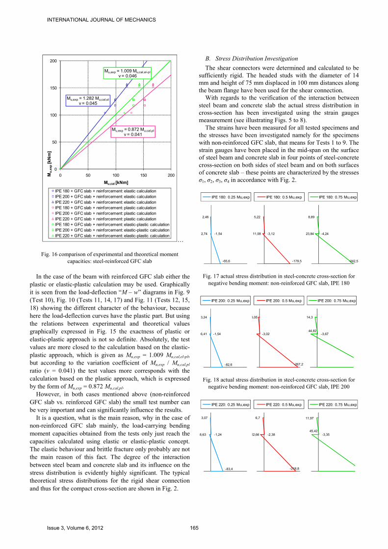
capacities: steel-reinforced GFC slab In the case of the beam with reinforced GFC slab either the plastic or elastic-plastic calculation may be used. Graphically it is seen from the load-deflection “M – w” diagrams in Fig. 9 (Test 10), Fig. 10 (Tests 11, 14, 17) and Fig. 11 (Tests 12, 15, 18) showing the different character of the behaviour, because here the load-deflection curves have the plastic part. But using the relations between experimental and theoretical values graphically expressed in Fig. 15 the exactness of plastic or elastic-plastic approach is not so definite. Absolutely, the test values are more closed to the calculation based on the elastic-plastic approach, which is given as Mu,exp = 1.009 Mu,cal,el-pl, but according to the variation coefficient of Mu,exp / Mu,cal,pl ratio (v = 0.041) the test values more corresponds with the calculation based on the plastic approach, which is expressed by the form of Mu,exp = 0.872 Mu,cal,pl. However, in both cases mentioned above (non-reinforced GFC slab vs. reinforced GFC slab) the small test number can be very important and can significantly influence the results. It is a question, what is the main reason, why in the case of non-reinforced GFC slab mainly, the load-carrying bending moment capacities obtained from the tests only just reach the capacities calculated using elastic or elastic-plastic concept. The elastic behaviour and brittle fracture only probably are not the main reason of this fact. The degree of the interaction between steel beam and concrete slab and its influence on the stress distribution is evidently highly significant. The typical theoretical stress distributions for the rigid shear connection and thus for the compact cross-section are shown in Fig. 2.
B. Stress Distribution Investigation
The shear connectors were determined and calculated to be sufficiently rigid. The headed studs with the diameter of 14 mm and height of 75 mm displaced in 100 mm distances along the beam flange have been used for the shear connection. With regards to the verification of the interaction between steel beam and concrete slab the actual stress distribution in cross-section has been investigated using the strain gauges measurement (see illustrating Figs. 5 to 8). The strains have been measured for all tested specimens and the stresses have been investigated namely for the specimens with non-reinforced GFC slab, that means for Tests 1 to 9. The strain gauges have been placed in the mid-span on the surface of steel beam and concrete slab in four points of steel-concrete cross-section on both sides of steel beam and on both surfaces of concrete slab – these points are characterized by the stresses σ1, σ2, σ3, σ4 in accordance with Fig. 2.
2,46
-1,542,74
-65,6
IPE 180: 0.25 Mu,exp
5,22
-3,1211,08
-179,5
IPE 180: 0.5 Mu,exp
8,89
-4,2423,84
-242,5
IPE 180: 0.75 Mu,exp
Fig. 17 actual stress distribution in steel-concrete cross-section for negative bending moment: non-reinforced GFC slab, IPE 180
3,24
-1,546,41
-82,6
IPE 200: 0.25 Mu,exp
8,05
-3,02
-267,2
IPE 200: 0.5 Mu,exp
14,3
-3,6744,82
IPE 200: 0.75 Mu,exp
Fig. 18 actual stress distribution in steel-concrete cross-section for negative bending moment: non-reinforced GFC slab, IPE 200
3,07
-1,248,63
-83,4
IPE 220: 0.25 Mu,exp
6,7
-2,3822,66
-218,8
IPE 220: 0.5 Mu,exp
11,97
-3,3545,42
IPE 220: 0.75 Mu,exp
INTERNATIONAL JOURNAL OF MECHANICS
Issue 3, Volume 6, 2012 165

Fig. 19 actual stress distribution in steel-concrete cross-section for negative bending moment: non-reinforced GFC slab, IPE 220
Some examples of the stress distribution in the beams of IPE 180, IPE 200 and IPE 220 with non-reinforced GFC slab are shown in Figs. 17, 18, 19. Here the stresses for bending moments of 0.25 Mu,exp, 0.5 Mu,exp and 0.75 Mu,exp are drawn. From the illustrated stress distributions it is evident, that the slip between steel beam and concrete slab occur, so that the shear connection cannot be considered like as rigid and does not ensure the perfect interaction. On that account the cross-section cannot be taken quite as compact and the substitute cross-section cannot be sufficiently used for the calculation of the capacity. However, surprisingly the values of the extreme actual and theoretical stresses in the beam and slab edges are not very different. Arising from the actual stress distribution and stress values compared to the theoretical stress values calculated using the substitute cross-section, the following relation between the actual second moments of area Iexp derived based on the test results evaluation and the theoretical second moments of area Isub calculated for the substitute cross-section can be observed:
subII ⋅= 753.0exp
. (3)
From the derivation mentioned above it can be deduced, in the case of non-reinforced slab the elastic approach is the most suitable for the determination of the negative bending moment capacity. It is possible to use the conception based on the rigid shear connection assumption and leading to the substitute cross-section with the second moment of area reduced to 75 % approximately.
V. CONCLUSIONS
Based on the experimental results and verification of the theoretical approaches realized in this part of the research some particular concluding remarks can be formulated:
• The negative bending moment capacity of the beam with non-reinforced GFC slab is almost comparable with the capacity of the beam with steel-reinforced concrete slab; however, the beams with GFC (only) do not give the plastic reserve because of GFC brittle behaviour.
• The negative bending moment capacity of the beam with steel-reinforced GFC slab with reduced amount of steel reinforcement is practically the same as the capacity of the beam with normal steel-reinforced slab with 5 times larger amount of steel reinforcement; in this case the beam gives the plastic reserve.
• In the case of the beam with non-reinforced GFC slab the elastic calculation is apposite; it is seen from the relation Mu,exp = 1.066 Mu,cal,el in Fig. 15 and it is confirmed by the variation coefficient (v = 0.172) of the Mu,exp / Mu,cal,el
ratio.
• In the case of the beam with steel-reinforced GFC slab either the plastic or elastic-plastic calculation may be used; however, in both cases the small test number can be
very important and can significantly influence the results.
• In the case of steel-concrete beam with non-reinforced GFC slab the elastic approach is the most suitable for the determination of the negative bending moment capacity; the assumption of the rigid shear connection may be used, but the second moment of area of the substitute cross-section must be reduced to about 75 %.
On the authors workplace the attention is intensively paid to the topics related to the problem presented here and particular results of the experimental and theoretical analysis have been published (see e.g. [3], [4], [9], [10], [11], [12], [13], [14]), some of them also with regard to the probabilistic analysis (especially the sensitivity analysis – see e.g. [5], [15], [16], [17]) aimed to the reliable and efficient structural design.
ACKNOWLEDGMENT
The paper has been elaborated within the framework of the following research projects solutions: Research Project No. MSM0021630519, Project of the Specific Research FAST S-11-32/1252 (both by the Czech Ministry of Education, Youth and Sport) and Grant Project No. 103/09/H085 (by the Czech Science Foundation).
REFERENCES
[1] M. Karmazínová, P. Bukovská, Theoretical and experimental analysis of load-carrying capacity of steel-concrete composite beams with glass-fibre-concrete slab, In Proceedings of the 5th International Conference
on Engineering Mechanics, Structures, Engineering Geology “EMESEG 12”, WSEAS Press: Cambridge, pp. 78-83. ISBN 978-1-61804-071-8.
[2] M. Karmazínová, Design assisted by testing – a powerful tool for the evaluation of material properties and design resistances from test results, International Journal of Mathematical Models and Methods in Applied
Sciences, Vol. 6, No. 1, 2012, pp. 376-385. ISSN 1998-0140. [3] M. Karmazínová, M. Štrba, V. Kvočák, Steel-concrete composite
members using high-strength materials in building constructions – structural design, actual behaviour, application, In Proceedings of the
2nd European Conference on Civil Engineering (“ECCIE´11”), North Atlantic University Union, WSEAS: Puerto de la Cruz, 2011, pp. 47-52. ISBN 978-1-61804-057-2.
[4] Z. Kala, L. Puklický, A. Omishore, M. Karmazínová, J. Melcher, Stability problems of steel-concrete members composed of high-strength materials, Journal of Civil Engineering and Management, 2010, 16(3), pp. 352-362. doi: 10.3846/jcem.2010.40.
[5] Z. Kala, M. Karmazínová, J. Melcher, L. Puklický, A. Omishore, Sensitivity analysis of steel-concrete structural members, In Proc. of the
9th International Conference on Steel-Concrete Composite and Hybrid
Structures ASCCS 2009 in Leeds, Research Publishing Services: Singapore, 2009, pp. 305-310. ISBN 978-981-08-3068-7.
[6] M. Karmazínová, J. J. Melcher, Methods of the design assisted by testing – applicable tools for the design resistance evaluation using test results, In Proceedings of the 2nd International Conference on
Mathematical Models for Engineering Science (“MMES´11”), Institute of Environment, Engineering, Economics and Applied Mathematics, WSEAS Press, Puerto de la Cruz, 2011, pp. 31-36. ISBN 978-1-61804-055-8.
[7] J. Melcher, M. Karmazínová, J. Pozdíšek, Experimental verification of behaviour of composite steel and glass-fibre-concrete beam, In Proceedings of the 9th International Conference on Steel-Concrete
Composite and Hybrid Structures „ASCCS 2009“ held in Leeds, Singapore: Research Publ. Services, 2009, pp. 390-395. ISBN 978-981-08-3068-7.
[8] M. Karmazínová, J. J. Melcher, Design assisted by testing applied to the determination of the design resistance of steel-concrete composite
INTERNATIONAL JOURNAL OF MECHANICS
Issue 3, Volume 6, 2012 166

columns, In Proceedings of the 13th WSEAS International Conference
on Mathematical and Computational Methods in Science and
Engineering MACMESE '11, WSEAS, Catania, 2011, pp. 420-425. ISBN 978-1-61804-046-6.
[9] M. Karmazínová, M. Pilgr, J. J. Melcher, Methods based on the approach of the design assisted by testing applied to the determination of material properties, In Proceedings of the 2nd International
Conference on Mathematical Models for Engineering Science
(“MMES´11”) “Mathematical Models and Methods in Modern Science”, Institute of Environment, Engineering, Economics and Applied Mathematics, WSEAS Press, Puerto de la Cruz, 2011, pp. 25-30. ISBN 978-1-61804-055-8.
[10] M. Karmazínová, J. Melcher, Z. Kala, Design of expansion anchors to concrete based on the results of experimental verification, Advanced
Steel Construction, an International Journal, Vol. 5, No. 4, Hong Kong Institute of Steel Construction, December 2009, pp. 390-405. ISSN 1816-112X.
[11] M. Karmazínová, J. Melcher, Z. Kala, Load-carrying capacity of post-installed steel anchors to concrete subjected to shear, In Proceedings of
the 3rd International Conference on Steel and Composite Structures
“ICSCS ´07“ held in Manchester, University of Manchester, 2007, pp. 449-454. ISBN 0415451418.
[12] M. Karmazínová, J. Melcher, Z. Kala, Actual Behaviour and Load-carrying Capacity of Steel Expansion Anchors to Concrete, In Proceedings of the 5th International Conference on Advances in Steel
Structures, Research Publishing Services: Singapore, 2007, Vol. III, p. 671-676. ISBN 978-981-05-9366-7.
[13] M. Karmazínová, J. J. Melcher, V. Röder Load-carrying capacity of steel-concrete compression members composed of high-strength materials, In Proceedings of the 9th International Conference on Steel-
Concrete Composite and Hybrid Structures „ASCCS 2009“, Leeds, Research Publishing Services: Singapore, 2009, pp. 239-244. ISBN 978-981-08-3068-7.
[14] M. Karmazínová, J. Melcher, M. Štrba, Fastening of steel structural members to concrete using post-installed mechanical fasteners, In Proceedings of 9th International Conference on Steel-Concrete
Composite and Hybrid Structures „ASCCS 2009“, Leeds, Research Publishing Services: Singapore 2009, pp. 549-554. ISBN 78-981-08-3068-7.
[15] J. Melcher, M. Škaloud, Z. Kala, M. Karmazínová, Sensitivity and statistical analysis within the elaboration of steel plated girder resistance, Advanced Steel Construction, an International Journal, Vol. 5, No. 2, Hong Kong Institute of Steel Construction, June 2009, pp. 120-126. ISSN 1816-112X.
[16] A. Omishore, Uncertainty Analysis of the Cross-sectional Area of a Structural Member, In Proceedings of the 4th WSEAS International
Conference on Engineering Mechanics, Structures, Engineering
Geology (EMESEG 11), WSEAS Press, Corfu Island, 2011, pp. 284-288. ISBN 978-1-61804-022-0.
[17] A. Omishore, Sensitivity Analysis of Structures, Problems and Applications, In Proceedings of the 6th WSEAS International
Conference on Applied and Theoretical Mechanics (MECHANICS 10), WSEAS Press, Athens, 2010, pp. 120-125. ISBN 978-960-474-264-6, ISSN 1792-5460.
[18] M. Karmazínová, J. J. Melcher, Analysis of the resistance of steel-concrete composite members composed of high-strength materials, In Proceedings of 10th International Conference on Steel, space and
composite structures “SS 11”, Famagusta, CI-premier: Singapore 2011. [19] M. Štrba, M. Karmazínová and J. Melcher, Reliable and effective design
of composite members – Steel-concrete composite members using high-strength materials, In Proceedings of the 6th European Conference on
Steel and Composite Structures “EUROSTEEL 2011”, Budapest, ECCS 2011, pp. 556-561. ISBN 978-92-9147-103-4.
[20] M. Karmazínová, J. J. Melcher, Possibilities of application of glass-fibre-concrete in composite steel-concrete beams, In Proceedings of the
9th International Symposium on Fiber-Reinforced Polymer
Reinforcement for Concrete Structures “FRPRCS-9” held in Sydney, University of Adelaide, 2009, p. 51 (book) + DVD (full version – 4 pages). ISBN 978 0 9806755 0 4.
[21] EN 1994-1-1 Design of Composite Steel and Concrete Structures – Part 1-1: General Rules and Rules for Buildings, CEN Brussels, 2006.
[22] EN 1992-1-1 Design of Concrete Structures – Part 1-1: General Rules and Rules for Buildings, CEN Brussels, 2006.
[23] EN 1993-1-1 Design of Steel Structures – Part 1-1: General Rules and Rules for Buildings, CEN Brussels, 2006.
INTERNATIONAL JOURNAL OF MECHANICS
Issue 3, Volume 6, 2012 167