analysis of the control structure of wind energy generation systems based on a permanent magnet...
DESCRIPTION
This paper presents the analysis of the two usual control structures for variable speed and fixed pitchwind energy generation systems, namely speed and torque control, to determine the most appropriatestructure to improve both robustness and reliability of this kind of distributed generators. The study considersall the elements of a typical wind power generation system and it has been carried out in a generalway, so that conclusions are independent of the kind of the AC/DC converter that it is used to process theenergy at the output of the generator. Particular emphasis was placed on developing a model of the turbinewhere the mechanical torque is considered as a system variable and not an exogenous disturbancefor the system, as in other previous studies. After showing that speed control presents several advantagesin terms of stability and reliability, an experimental study of this technique was carried out by using agrid connected wind generation system, which is composed by a three-phase boost rectifier feedingthe grid connected inverter. Other practical issues for the design of high efficient wind generation systems,like the use of a Kalman speed estimator to avoid the need of mechanical sensors, are also implementedin the prototype and discussed in the paper.TRANSCRIPT

Applied Energy 103 (2013) 522–538
Contents lists available at SciVerse ScienceDirect
Applied Energy
journal homepage: www.elsevier .com/ locate/apenergy
Analysis of the control structure of wind energy generation systems basedon a permanent magnet synchronous generator
O. Carranza a,⇑, E. Figueres b, G. Garcerá b, R. Gonzalez-Medina b
a Escuela Superior de Cómputo, Instituto Politécnico Nacional, Av. Juan de Dios Batiz S/N, Col. Lindavista, Del. Gustavo A. Madero, México 07738, DF, Mexicob Grupo de Sistemas Electrónicos Industriales, Departamento de Ingeniería Electrónica, Universidad Politécnica de Valencia, Camino de Vera S/N, 7F, 46020 Valencia, Spain1
h i g h l i g h t s
" We have presented the analysis of two control structures for WEGS." The analysis of both control structures include all the elements of a WEGS." The analysis of both control structure are independent of the converter topologies." The speed control scheme is best suited for implementation." The speed control scheme for WEGS has been evaluated experimentally.
a r t i c l e i n f o
Article history:Received 18 June 2012Received in revised form 3 October 2012Accepted 4 October 2012Available online 3 November 2012
Keywords:WGSPMSGTorque controlSpeed control
0306-2619/$ - see front matter � 2012 Elsevier Ltd. Ahttp://dx.doi.org/10.1016/j.apenergy.2012.10.015
⇑ Corresponding author.E-mail addresses: [email protected] (O. Ca
(E. Figueres), [email protected] (G. Garcerá).1 http://www.gsei.upv.es
a b s t r a c t
This paper presents the analysis of the two usual control structures for variable speed and fixed pitchwind energy generation systems, namely speed and torque control, to determine the most appropriatestructure to improve both robustness and reliability of this kind of distributed generators. The study con-siders all the elements of a typical wind power generation system and it has been carried out in a generalway, so that conclusions are independent of the kind of the AC/DC converter that it is used to process theenergy at the output of the generator. Particular emphasis was placed on developing a model of the tur-bine where the mechanical torque is considered as a system variable and not an exogenous disturbancefor the system, as in other previous studies. After showing that speed control presents several advantagesin terms of stability and reliability, an experimental study of this technique was carried out by using agrid connected wind generation system, which is composed by a three-phase boost rectifier feedingthe grid connected inverter. Other practical issues for the design of high efficient wind generation sys-tems, like the use of a Kalman speed estimator to avoid the need of mechanical sensors, are also imple-mented in the prototype and discussed in the paper.
� 2012 Elsevier Ltd. All rights reserved.
1. Introduction area [2]. Largely on the world there are several projects as wind
Due to the high cost of fossil fuels used in conventional gener-ation system and the high pollution generated by these systems.Currently, develop power generation systems employing alterna-tive energy sources are an interesting solution. Generation systemsbased on renewable energy are having a boom around the world,one of these systems are wind generation systems (WGSs) [1]. Inthe case of wind energy systems is necessary for statistical studiesto determine the appropriate place to take full advantage of thisenergy, these studies estimate the average wind speed, the windpower density and its capacity factor for a specific geographical
ll rights reserved.
rranza), [email protected]
farms, which seek to increase the amount of electrical energy fromwind, getting with this increase the amount of clean electricalenergy [3]. An important issue in the implementation of windenergy systems is to establish the viability and relative generationcapacity to conventional generation systems. It also seeks toreduce the cost of the power generation with the implementationof wind energy systems [4]. Due to the versatility of wind genera-tion systems, these can be implemented in different applicationsand environments, such as a primary energy source in remote loca-tions, with the support of storage systems to provide energy at alltimes [5], as well as, these can be used in distributed generationsystems in context the microgrids working both island mode andgrid connected mode [6,7].
In low power WGS, there are used two types of generators,these are induction generators (IGs) and permanent magnetsynchronous generators (PMSGs) [8–10]. The IGs need external

O. Carranza et al. / Applied Energy 103 (2013) 522–538 523
magnetization and use a gearbox, whether directly to the grid orindirectly to the grid by using of a back-to-back converter. In thecase of directly connecting to the grid, the generator is limited toa fixed speed, so that does not work in a wide range of wind speed;consequently the power that is extracted is reduced [8]. In the caseof indirectly connexion to the grid, the generator operates at vari-able speed, due to employment of the converter, which ensuresgreater amount of power extracted, however, this topology is verycomplex and expensive to be used in WGS low cost. Furthermore,the PMSGs do not require external magnetization, so that may beemployed in isolated grid. Because they are constructed of severalpairs of poles, it is not necessary to use gearbox. PMSG work in awide range of wind speed, which is extracted as much energy fromthe wind [10,11]. Accordingly in WGS low power, PMSGs are pre-ferred to IG.
PMSG cannot connect directly to the mains; because both theoutput voltages and frequency depend on wind speed, then isnecessary a power conversion system for coupling the energyextracted from the generator and the energy which is injected intothe grid. This system should consist of an AC/DC converter (recti-fier), which has the function of converting the AC signal from thegenerator to DC signals, so that through a DC/AC converter (inver-ter) is injected into the grid. For AC/DC converter, there are basi-cally two topologies used in WGS. The first type is a rectifier anda DC/DC converter and the second type is a controlled rectifier,which together with inverter is commonly known as a converterback-to-back. Inverter is responsible for controlling both the activeand reactive power is injected to the grid, also inverter usually con-trols the voltage of the DC-Link.
One of the most important issues in wind power generationsystems is to extract as much energy as possible from the wind,seeking to achieve high levels of efficiency and quality of the en-ergy that it is injected into the grid. To achieve that, it is mandatoryto implement the proper control strategies [12,13]. For the caseunder study, the system operates at variable speed and fixed pitch,so that the usual control structures are torque control and speedcontrol. Note that in both cases there is a torque loop that regulatesthe generator output current, but in the case of speed control thetorque loop receives a reference signal from the speed regulator,where the regulated variable is the PMSG speed [14]. Figs. 1 and2 show the scheme of torque and speed control, respectively. TheMPPT block represents the algorithm of the maximum power point
Fig. 1. Block diagram of the torqu
tracking (MPPT) that provides the reference current (Iref) for thetorque control scheme, providing the speed reference (xref) forthe speed control loop if this technique is used. The study of MPPTis outside the scope of this paper.
This paper is focused on the analysis of both speed and torquecontrol structures. It is worth to point out that the dynamics ofthe wind turbine have been taken into account in the analysis, sothat the mechanical torque is considered as an internal variableof the system and not simply as a disturbance, simplification thatis usual in the study of motor control applications [14]. After show-ing in a general way that the speed control approach offers advan-tages in terms of stability and easier design, a detailed descriptionof that control technique applied to WGS is presented and experi-mentally tested. The experimental prototype is a three-phase boostrectifier working in Discontinuous Conduction Mode (DCM), whichfeeds a grid connection inverter. This topology was presented in[15], showing that it presents some advantages with regard toother low cost topologies, like reduced value of the total harmonicdistortion at the generators output current and high power factorin the whole speed range of the PMSG. As a result, the system effi-ciency is increased and the mechanical stress of the generator isdecreased.
Table 1 shows the values of the parameters of the WGS understudy.
2. Fundamentals of wind turbines based on PMSG
The mechanical behavior of the wind turbine follows (1)
Jdxm
dtþ Bxm ¼ Tm � Te ð1Þ
where J is inertia coefficient, B is the friction coefficient, xm is theturbine rotational speed, Tm is the turbine mechanical torque andTe is the electrical torque applied to the PMSG rotor.
The mechanical power generated by the wind turbine (Pm) andthe applied torque Tm are expressed by Eqs. (2) and (3),respectively.
Pm ¼12qpr2CpðkÞV3
x ð2Þ
Tm ¼12qpr3CtðkÞV2
x ð3Þ
e control structure for WGS.
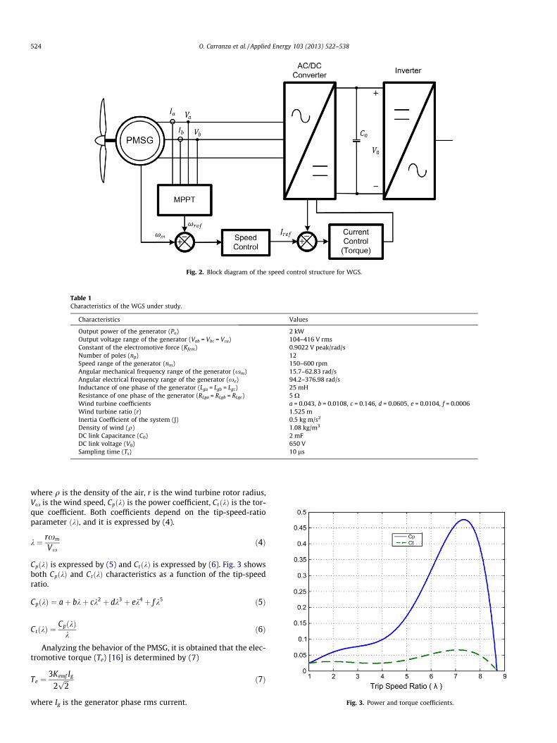
Fig. 2. Block diagram of the speed control structure for WGS.
Table 1Characteristics of the WGS under study.
Characteristics Values
Output power of the generator (Po) 2 kWOutput voltage range of the generator (Vab = Vbc = Vca) 104–416 V rmsConstant of the electromotive force (Kfem) 0.9022 V peak/rad/sNumber of poles (np) 12Speed range of the generator (nm) 150–600 rpmAngular mechanical frequency range of the generator (xm) 15.7–62.83 rad/sAngular electrical frequency range of the generator (xe) 94.2–376.98 rad/sInductance of one phase of the generator (Lga = Lgb = Lgc) 25 mHResistance of one phase of the generator (RLga = RLgb = RLgc) 5 XWind turbine coefficients a = 0.043, b = 0.0108, c = 0.146, d = 0.0605, e = 0.0104, f = 0.0006Wind turbine ratio (r) 1.525 mInertia Coefficient of the system (J) 0.5 kg m/s2
Density of wind (q) 1.08 kg/m3
DC link Capacitance (C0) 2 mFDC link voltage (V0) 650 VSampling time (Ts) 10 ls
524 O. Carranza et al. / Applied Energy 103 (2013) 522–538
where q is the density of the air, r is the wind turbine rotor radius,Vx is the wind speed, CpðkÞ is the power coefficient, CtðkÞ is the tor-que coefficient. Both coefficients depend on the tip-speed-ratioparameter ðkÞ, and it is expressed by (4).
k ¼ rxm
Vxð4Þ
CpðkÞ is expressed by (5) and CtðkÞ is expressed by (6). Fig. 3 showsboth CpðkÞ and CtðkÞ characteristics as a function of the tip-speedratio.
CpðkÞ ¼ aþ bkþ ck2 þ dk3 þ ek4 þ f k5 ð5Þ
Fig. 3. Power and torque coefficients.
CtðkÞ ¼CpðkÞ
kð6Þ
Analyzing the behavior of the PMSG, it is obtained that the elec-tromotive torque (Te) [16] is determined by (7)
Te ¼3Kemf Ig
2ffiffiffi2p ð7Þ
where Ig is the generator phase rms current.

Fig. 4. Dependence of the generator output power ðbPoutÞ.
O. Carranza et al. / Applied Energy 103 (2013) 522–538 525
3. Modeling of the wind generation system
The main goal in wind power generation systems is to extractthe greatest amount of wind energy and convert it to electricenergy. This is achieved with an adequate control structure that al-lows the system to be stable in the range of operation and anappropriate algorithm of maximum power point tracking. The goalof the MPPT is to extract as much energy, for which, the MPPTadjusts the operating point of the system to be controlled in orderto achieve maximum power available from the wind [17–19].
Considering the electrical losses of the generator and assumingthat the torque induced in the turbine is equal to the electricaltorque in the generator, the generator output power may beexpressed by
Pout ¼ Texm � RLgaI2g ð8Þ
Fig. 5. The basic block diagram of torque control structure in the wind generatorsystem.
Fig. 6. The basic block diagram of speed contro
Applying (7) in (8), it is obtained:
Pout ¼3Kfemffiffiffi
2p Igxm � RLgaI2
g ð9Þ
Although the power function is not linear, a linear model of Pout maybe obtained by applying a first order Taylor series around the oper-ation point. This linear model allows a small-signal analysis todetermine which is the most suitable control. The small signal mod-el represents variations or disturbances in the system operatingpoint [20]. The following nomenclature is adopted: any dynamicvariable x is represented as: ¼ X þ x, where X is the operation pointvalue and x is the small-signal term.
bPout ¼ xm@½Poutðxm; igÞ�
@xm
����xm ¼Wm
ig ¼ Ig
þ ig@½Poutðxm; igÞ�
@ig
����xm ¼Wm
ig ¼ Ig
ð10Þ
Applying (9) in (10), it is obtained
bPout ¼ xm
@3Kfemffiffi
2p igxm�RLgai2
g
h i@xm
������xm ¼Wm
ig ¼ Ig
þ ig
@3Kfemffiffi
2p igxm�RLgai2
g
h i@ig
������xm ¼Wm
ig ¼ Ig
ð11Þ
Developing the partial derivatives, it is obtained
bPout ¼ xm3Kfemffiffiffi
2p ig
����xm ¼Wm
ig ¼ Ig
þ ig3Kfemffiffiffi
2p xm � 2RLgaig
����xm ¼Wm
ig ¼ Ig
ð12Þ
Evaluating, it is obtained
bPout ¼ xm3Kfemffiffiffi
2p Ig þ ig
3Kfemffiffiffi2p Wm � 2RLgaIg
� �ð13Þ
From (13), the analysis can be performed to know which of the twoconsidered control structures is most appropriate for WGS. Notethat the generator output power depends on both the generatorcurrent and the generator speed, as Fig. 4 shows.
Figs. 5 and 6 show the basic block diagrams of torque controland speed control, respectively. In the first case, the dependenceof the generated power with the torque ðbPout=bT eÞ should be ob-tained, but it is preferred to calculate ðbPout=bT gÞ because the gener-ator current is the true regulated variable. Note that the generatortorque has a direct relationship with the current generator as (9)shows, so that the torque is indirectly regulated by closing the cur-rent control loop.
l structure in the wind generator system.

Fig. 7. Block diagram of the mechanical behavior of the wind generation system.
526 O. Carranza et al. / Applied Energy 103 (2013) 522–538
Starting from Eq. (13), it is obtained (14). In (14) it is observedthat €Pout =ig depends on the relationship between the generatorspeed and the generator current ðxm=igÞ.bPout
ig
¼ xm
ig
3Kfemffiffiffi2p Ig þ
3Kfemffiffiffi2p Wm � 2RLgaIg ð14Þ
To analyze the speed control structure, the expression ðbPout=xmÞis needed. Starting from Eq. (13), it is obtained (15). In (15) it isobserved that €Pout =ig depends on the relationship between thegenerator current and the generator speed ðig=xmÞ.
Fig. 8. Block diagram of the mechanical behavior model of WG
Fig. 9. Bode diagrams of the relationship between the PMSG
bPout
xm¼ 3Kfemffiffiffi
2p Ig þ
ig
xm
3Kfemffiffiffi2p Wm � 2RLgaIg
� �ð15Þ
In both control structures it is necessary to know the relation-ship between the generator speed and the generator current. Start-ing from Eq. (1), it is obtained (16).
xm ¼1JsðTm � TeÞ ð16Þ
Fig. 7 shows the block diagram of the mechanical behavior of thewind generation system. Tm is normally considered as an externaldisturbance for the system. However, Tm strongly depends on boththe speed of the PMSG, xm, and on the wind speed, mx, as it isshown in (3)–(6). Te depends on Ig as (7) shows.
Applying (4)–(6) in (3), it is obtained:
Tm ¼12qpr3 avx
rxmþ bþ crxm
vxþ dr2x2
m
v2xþ e
r3x3m
v3xþ f
r4x3m
v4x
!v2
x
ð17Þ
Although Tm is a not linear function, a linear model of Tm may beobtained by applying a first order Taylor series around an operationpoint. Note that one of the inputs of the resulting linear model is the
S, considering the wind speed as an external disturbance.
speed and generator current ðxm =igÞ for Vx = 10 m/s.
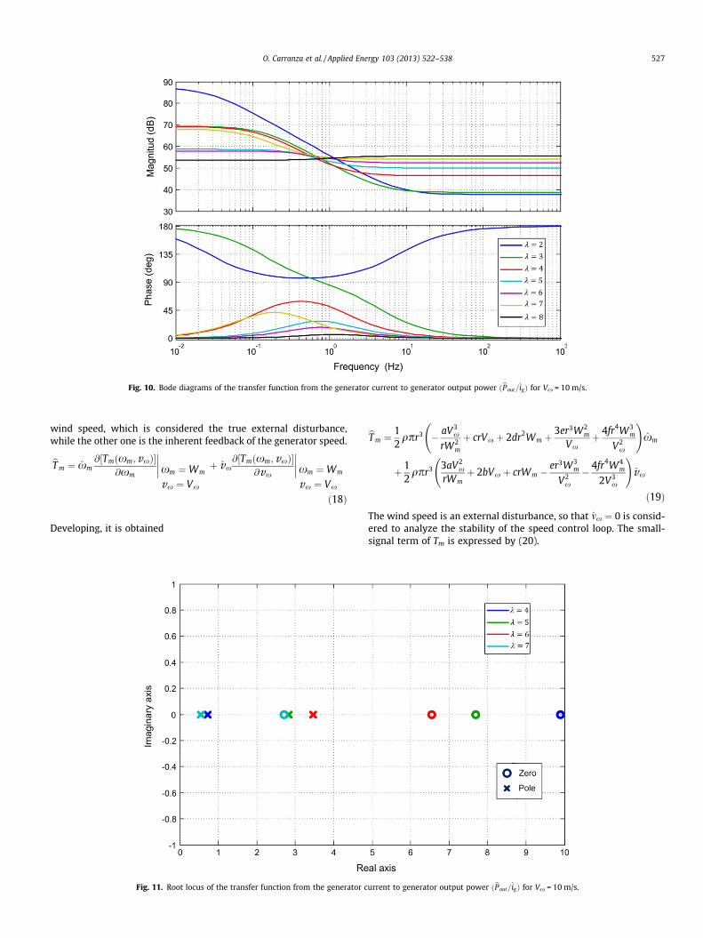
Fig. 10. Bode diagrams of the transfer function from the generator current to generator output power ðbPout =igÞ for Vx = 10 m/s.
O. Carranza et al. / Applied Energy 103 (2013) 522–538 527
wind speed, which is considered the true external disturbance,while the other one is the inherent feedback of the generator speed.
bT m ¼ xm@½Tmðxm;vxÞ�
@xm
����xm ¼Wm
vx ¼ Vx
þ vx@½Tmðxm; vxÞ�
@vx
����xm ¼Wm
vx ¼ Vx
ð18Þ
Developing, it is obtained
Fig. 11. Root locus of the transfer function from the generator c
bT m ¼12qpr3 � aV3
x
rW2m
þ crVx þ 2dr2Wm þ3er3W2
m
Vxþ 4fr4W3
m
V2x
!xm
þ 12qpr3 3aV2
x
rWmþ 2bVx þ crWm �
er3W3m
V2x
� 4fr4W4m
2V3x
!vx
ð19Þ
The wind speed is an external disturbance, so that mx ¼ 0 is consid-ered to analyze the stability of the speed control loop. The small-signal term of Tm is expressed by (20).
urrent to generator output power ðbPout =igÞ for Vx = 10 m/s.

Fig. 12. Bode diagrams of the transfer function from the generator speed to generator output power ðPout=xmÞ for Vx = 10 m/s.
528 O. Carranza et al. / Applied Energy 103 (2013) 522–538
bT m
���vx¼0¼1
2qpr3 � aV3
x
rW2m
þcrVxþ2dr2Wmþ3er3W2
m
Vxþ4fr4W3
m
V2x
!xm
ð20Þ
The small-signal expression of the electrical torque may beobtained from (7), resulting in (21).
bT e ¼3Kfemigffiffiffi
2p ð21Þ
Considering that there are not variations in the wind speed,mx ¼ 0, the PMSG speed is expressed by (22). Fig. 8 shows the blockdiagram of the mechanical behavior of wind generation systems,considering the wind speed as the true disturbance for the system.
xm ¼1Js
bT m
���vx¼0
� bT eðigÞ� �
ð22Þ
Fig. 13. Scheme of three-phase boost re
From (20)–(22), it is obtained
xm ¼1Js
12qpr3 � aV3
x
rW2m
þcrVxþ2dr2Wmþ3er3W2
m
Vxþ4fr4W3
m
V2x
!xm�
3Kfemigffiffiffi2p
" #ð23Þ
From Eq. (23), it is possible to deduce the relationship between thePMSG speed and the generator current, following (24).
GxgðsÞ¼ xm
ig¼� 3Kfemffiffi
2p
Js�12qpr3c1½ �
c1¼ � aV3x
rW2mþcrVxþ2dr2Wmþ 3er3W2
mVxþ 4fr4W3
m
V2x
� � ð24Þ
Fig. 9 shows the Bode diagrams of the relationship between thePMSG speed and the generator current ðxm=igÞ as a function of k,for Vx ¼ 10 m=s.
ctifier operating in DCM with PCC.

Fig. 14. Peak current-mode control loop.
O. Carranza et al. / Applied Energy 103 (2013) 522–538 529
4. Torque control vs speed control
In this section a comparative study of both torque and speedcontrol schemes is presented to determine which control structureis the most suitable for use in the proposed wind generationsystem.
Starting from (14) and (24), the transfer function from thegenerator current to generator output power can be obtained,following (25).
bPout
xm¼ 3Kfemffiffiffi
2p Ig � Wm �
2ffiffiffi2p
RLgaIg
3Kfem
!Js� 1
2qpr3c1
�
c1 ¼ � aV3x
rW2m
þ crVx þ 2dr2Wm þ3er3W2
m
Vxþ 4fr4W3
m
V2x
! ð25Þ
Fig. 10 shows the Bode diagrams of the transfer function from thegenerator current to generator output power ðbPout =igÞ as a functionof k, for Vx ¼ 10 m=s.
Fig. 15. Bode diagram of the transfer function from the dut
Fig. 10 shows that €Pout =ig is unstable for k values greater than 3.This is corroborated in Fig. 11, which shows the location of theroots of €Pout =ig , for k values between 4 and 7. Note that the polesand zeros are in the right half plane at very low frequency and veryclose one to each other for different operating points. Therefore,the torque control scheme is very complicated to implement byusing classical control theory.
Starting from (15) and (24) the transfer function from thegenerator speed to the generator output power can be obtained,following (26).
bPout
xm¼ 3Kfemffiffiffi
2p Ig � Wm �
2ffiffiffi2p
RLgaIg
3Kfem
!Js� 1
2qpr3c1
�
c1 ¼ � aV3x
rW2m
þ crVx þ 2dr2Wm þ3er3W2
m
Vxþ 4fr4W3
m
V2x
! ð26Þ
Fig. 12 shows the Bode diagrams of the transfer function from thegenerator speed to generator output power ðbPout=xmÞ as a functionof k, for Vx ¼ 10 m=s.
Fig. 12 shows that bPout=xm is a non-minimum phase transferfunction for several values of k, due it contains zeroes in the righthalf plane, which causes the phase angle not follow the samebehavior as the magnitude. It is slow in responding because of itsbehavior at the star of a response [21]. Therefore, the speed controlstructure can be easily designed and implemented by using classi-cal control techniques.
5. Sample design and implementation of speed control
5.1. AC/DC converter and current control loop
The chosen AC/DC converter is a three-phase boost rectifieroperating in DCM, which is shown by Fig. 13. A Peak Current ModeControl (PCC) has been chosen to regulate the generator currents.PCC is the most used in switching power supplies, as it gives astrict adherence to the current in the inductor, which is highly
y cycle to the equivalent boost inductor current Gid(s).

Fig. 16. Bode diagram of the current loop gain Ti(s).
530 O. Carranza et al. / Applied Energy 103 (2013) 522–538
recommended when working in DCM. Furthermore, PCC is con-trolled by the peak current in the inductor or power active switch(power transistor), so that there is an inherent overcurrent protec-tion control [20,22,23]. Such a control scheme was presented andanalyzed in detail in [15].
Fig. 14 shows the block diagram of the current loop with PCC[23]. The reference for the current loop, Iref, is provided by the con-troller of the speed control loop.
The current loop gain, Ti(s), is determined by (27) and the closedloop gain of the current loop, Gic(s), is given by (28).
Fig. 17. Bode diagram of the closed lo
TiðsÞ ¼ GidðsÞHeðsÞRiFM ð27Þ
GicðsÞ ¼iLðsÞ
iref ðsÞ¼ GidðsÞFM
1þ TiðsÞð28Þ
where Gid(s), He(s) and FM are the transfer function from the dutycycle to the equivalent boost inductor current, sampling gain andPWM modulator gain, respectively, which are detail in [15]. Figs.15–17 show the Bode plot of Gid(s), Ti(s) and Gic(s), respectively,for various values of the generator speed.
op gain of the current loop Gic(s).
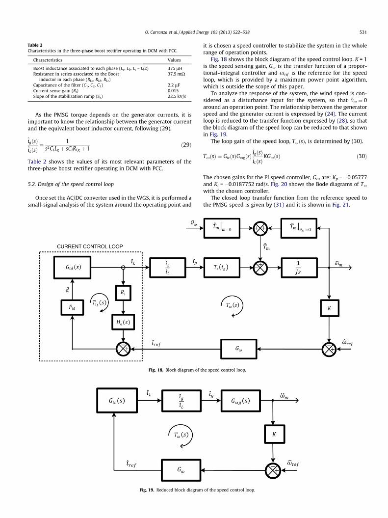
Table 2Characteristics in the three-phase boost rectifier operating in DCM with PCC.
Characteristics Values
Boost inductance associated to each phase (La, Lb, Lc = L/2) 375 lHResistance in series associated to the Boost
inductor in each phase (RLa, RLb, RLc)37.5 mX
Capacitance of the filter (C1, C2, C3) 2.2 lFCurrent sense gain (Ri) 0.015Slope of the stabilization ramp (Se) 22.5 kV/s
O. Carranza et al. / Applied Energy 103 (2013) 522–538 531
As the PMSG torque depends on the generator currents, it isimportant to know the relationship between the generator currentand the equivalent boost inductor current, following (29).
igðsÞiLðsÞ
¼ 1s2CiLg þ sCiRLg þ 1
ð29Þ
Table 2 shows the values of its most relevant parameters of thethree-phase boost rectifier operating in DCM with PCC.
5.2. Design of the speed control loop
Once set the AC/DC converter used in the WGS, it is performed asmall-signal analysis of the system around the operating point and
Fig. 18. Block diagram of t
Fig. 19. Reduced block diagram
it is chosen a speed controller to stabilize the system in the wholerange of operation points.
Fig. 18 shows the block diagram of the speed control loop. K = 1is the speed sensing gain, Gx is the transfer function of a propor-tional–integral controller and xref is the reference for the speedloop, which is provided by a maximum power point algorithm,which is outside the scope of this paper.
To analyze the response of the system, the wind speed is con-sidered as a disturbance input for the system, so that mx ¼ 0around an operation point. The relationship between the generatorspeed and the generator current is expressed by (24). The currentloop is reduced to the transfer function expressed by (28), so thatthe block diagram of the speed loop can be reduced to that shownin Fig. 19.
The loop gain of the speed loop, TxðsÞ, is determined by (30).
TxðsÞ ¼ GicðsÞGxgðsÞigðsÞiLðsÞ
KGxðsÞ ð30Þ
The chosen gains for the PI speed controller, Gx are: Kp = �0.05777and Ki = �0.0187752 rad/s. Fig. 20 shows the Bode diagrams of Tx
with the chosen controller.The closed loop transfer function from the reference speed to
the PMSG speed is given by (31) and it is shown in Fig. 21.
he speed control loop.
of the speed control loop.

Fig. 20. Bode diagram of the speed loop gain Tx(s), at a wind speed of 6 m/s.
532 O. Carranza et al. / Applied Energy 103 (2013) 522–538
Gxr ¼xm
xref¼
GicðsÞGxgðsÞ ig ðsÞiLðsÞ
GxðsÞ1þ Tx
ð31Þ
5.3. Speed estimator
Due to both the voltages and frequency of the generator dependon its speed, the PMSG speed can be estimated starting from themeasurement of the electrical quantities, eliminating the needfor mechanical sensors. The problem is that the measured signalscontain low frequency harmonics of the fundamental frequencyof the generator, as well as switching frequency components due
Fig. 21. Bode diagram of transfer function of the speed c
to the boost rectifier. Furthermore, the fundamental and its lowfrequency harmonics have different values depending on the gen-erator speed. These issues have been studied in detail in [24], con-cluding that the use of a Linear Kalman Filter (LKF) is a goodcompromise among dynamical response, static performance andcomplexity of implementation. In this case sensors are used tomeasure the generator output voltages in order to apply the LKFspeed estimation. The main equations of the LKF used in this workare expressed by (32). The meaning of each variable of (32) isexplained in [24]. The chosen values of the LKF parameters are:d = 5 � 106, Ks1 = 0.0032896, Ks2 = 0.54221 and Ks3 = 0.00044647.
ontrol loop closed, Gxr(s), at a wind speed of 6 m/s.

Fig. 22. Scheme of the proposed WGS.
O. Carranza et al. / Applied Energy 103 (2013) 522–538 533
eðkÞ ¼ VbðkÞ cos hðkÞ � VaðkÞ sin h
hðkþ 1Þ ¼ hðkÞ þ TsxeðkÞ þ Ks1eðkÞxeðkþ 1Þ ¼ xeðkÞ þ qðkÞ þ Ks2eðkÞqðkþ 1Þ ¼ qðkÞ þ Ks3eðkÞ
ð32Þ
6. Simulation results
The performance of the proposed WECS has been evaluated bymeans of PSIM 7.0.5 software [25]. Fig. 22 shows the scheme of theproposed WECS. The system includes boost rectifier in DCM withinput filter and PCC control, the wind turbine model, the speedestimator and the speed loop with the designed controller.
In order to evaluate the dynamic performance of the speed con-trol structure, steps are applied in the reference speed to observe
Fig. 23. Response of the speed loop to speed reference steps at a wind speed of 6 m/s.electric torque.
the behavior of the WGS, assuming a constant wind speed. Thesteps ðDxref Þ are 20 rpm, the update time ðDtÞ of the reference is10 s and the considered wind speeds are 6 m/s and 10 m/s. The ref-erence speed starts at 150 rpm, however, the WGS is limited to amaximum reference speed, according to the behavior of the tur-bine, so for the case of 6 m/s, the maximum speed is 310 rpmand for 10 m/s, it is 530 rpm.
Figs. 23 and 24 show the behavior of the speed loop to stepsin the speed reference at a constant wind speed of 6 m/s and10 m/s, respectively. It is observed that the speed loop properlyfollows the reference value. These figures also show the behaviorof the electric torque and the PMSG output power. It is observedthat the speed loop properly follows the reference value in allcases.
Top: generator speed and its reference. Middle: generator output power. Bottom:

Fig. 24. Response of the speed loop to speed reference steps at a wind speed of 10 m/s. Top: generator speed and its reference. Middle: generator output power. Bottom:electric torque.
534 O. Carranza et al. / Applied Energy 103 (2013) 522–538
Figs. 25 and 26 show in detail the speed loop response to stepsin the reference speed. It may be observed that the speed loop al-ways follows the setpoint established by the reference speed,regardless of the wind speed value and whether the referencespeed increase or decrease, thereby demonstrating the good per-formance of the speed control structure.
7. Experimental results
The following tests were carried out to experimentally validatethe performance of the designed speed loop. Fig. 27 shows the
Fig. 25. Detail of the speed loop response to steps at
scheme used for carrying out the experimental tests to evaluatethe speed loop in the proposed wind power generation system.In these tests the sensorless technique described in Section 5.3has been implemented to calculate the PMSG speed.
To emulate the wind turbine characteristics, the 2 kW PMSG isconnected to a commercial AC motor drive Siemens Micromaster440 that feeds a 5.5 kW induction motor 1LE1002CC322AA4Z fromSiemens. With the AC motor drive, different wind speeds can beemulated by properly adjusting its speed reference, following aprogrammed wind turbine model. The PCC circuit for the boostconverter has been implemented around an UC3823 integrated
the reference speed, for a wind speed of 6 m/s.

Fig. 26. Detail of the speed loop response to steps at the reference speed, for a wind speed of 10 m/s.
O. Carranza et al. / Applied Energy 103 (2013) 522–538 535
circuit. The wind speed emulation, speed control loop and genera-tor speed estimation have been implemented by means of a DSPTMS320F28335. Table 1 shows the most relevant values of theexperimental WES.
Some of the oscilloscope waveforms shown in the following areinternal variables that are processed inside the DSP. Those vari-ables are displayed by using the DSP PWM outputs and an analoglow pass filter with a cutoff frequency of 300 Hz. This is a simpleway to display some slow variables inside a DSP without the need
Fig. 27. Scheme of the exp
of a digital to analog converter. The displayed internal DSP vari-ables are: the estimated speed with a scale factor of 133.69 rpm/V, the speed reference with a scale factor of 133.69 rpm/V, the gen-erated power with a scale factor of 500 W/V, the electric torquewith a scale factor of 14 Nm/V, the power coefficient with a scalefactor of 0.12/V, and the wind speed with a scale factor of 2.4 m/s/V.
Figs. 28 and 29 depict the response of the speed loop to astepped speed reference at a wind speed of 6 m/s and 10 m/s,
erimental prototype.

Fig. 28. Response of the speed loop to a stepped speed reference at a wind speed of 6 m/s. Reference speed (133,69 rpm/V, 500 mV/div). Estimated speed by means of the LKFestimator (133,69 rpm/V, 500 mV/div). Electric torque (14 Nm/V, 500 mV/div). PMSG power output (500 W/V, 500 mV/div): (a) time scale: 20 s/div and (b) time scale: 10 s/div.
Fig. 29. Response of the speed loop to a stepped speed reference at a wind speed of 10 m/s. Reference speed (133,69 rpm/V, 500 mV/div). Estimated speed by means of theLKF estimator (133,69 rpm/V, 500 mV/div). Electric torque (14 Nm/V, 500 mV/div). PMSG power output (500 W/V, 500 mV/div): (a) time scale: 50 s/div and (b) time scale:20 s/div.
536 O. Carranza et al. / Applied Energy 103 (2013) 522–538
respectively. It is observed that the speed loop properly follows thespeed reference. These figures also show the behavior of electrictorque and the PMSG output power. A great agreement can be ob-served between these experimental results and the simulated onesof Figs. 23 and 24.
The tests were performed by applying a series of ascending anddescending speed steps for a given and constant wind speed. Thespeed steps have an amplitude of 20 rpm every 10 s, all tests beginto 150 rpm but are limited to a maximum step, according to thebehavior of the turbine, so that in the case of 6 m/s reaches310 rpm and in the case of 10 m/s to 530 rpm.
The speed loop responds to all wind speeds with appropriatemonitoring of the reference speed set, both upward and downwardsteps. It is also observed behavior of electric torque and power out-put GSIP as expected.
Figs. 30 and 31 show in detail the response to both ascendingand descending speed steps for a wind speed of 6 m/s and 10 m/
s, respectively. The graphs in yellow represent the reference speedand the green plots represent the speed estimated by the LKF. Agood performance of the speed control loop is observed in all cases.
8. Conclusions
This paper has presented the analysis of two control structuresfor wind power generation systems. The analysis of both controlstructures has taken into account all the elements of a wind powergeneration system, taking great care of the turbine model, whichconsiders the mechanical torque as a system variable and not a dis-turbance as in other studies. Furthermore, the analysis of the con-trol structure is developed to be independent of the chosen powerconverter topologies.
The study has concluded that the speed control scheme is bestsuited for implementation because it is designed to stabilize a non-minimum phase system, so that a classical and easy to implement

Fig. 30. Detail of the speed loop experimental response to steps at the reference speed, for a wind speed of 6 m/s. Reference speed (133,69 rpm/V, 100 mV/div). Estimatedspeed by means of the LKF estimator (133,69 rpm/V, 100 mV/div). Time scale: 5 s/div.
Fig. 31. Detail of the speed loop experimental response to steps at the reference speed, for a wind speed of 10 m/s. Reference speed (133,69 rpm/V, 100 mV/div). Estimatedspeed by means of the LKF estimator (133,69 rpm/V, 100 mV/div). Time scale: 5 s/div.
O. Carranza et al. / Applied Energy 103 (2013) 522–538 537
PI controller may be used. On the contrary, the torque controlscheme is applied to a system that has a pole and a zero in the righthalf plane, at a very low frequency and very close to each other, soit is very difficult to stabilize the system, at least by using the clas-sical control theory.
Finally, a sample design of the speed control scheme for WEShas been presented and experimentally evaluated, showing thatthis approach offers an excellent performance to place the PMSGat the desired speed operation point to extract as much energyas possible from the wind, following a consigned for the speed loopthat would be calculated by a maximum power point algorithm.
Acknowledgements
The first author thanks the support of the Instituto PolitécnicoNacional (IPN) and of the Comisión de Operación y Fomento deActividades Académicas (COFAA). This work was supported bythe Spanish Ministry of Science and Innovation under GrantENE2009-13998-C02-02.
References
[1] Li H, Chen Z. Overview of different wind generator systems and theircomparisons. IET Renew Power Gener 2008;2(2):123–38.
[2] Jowder Fawzi AL. Wind power analysis and site matching of wind turbinegenerators in Kingdom of Bahrain. Appl Energy 2009;86(4):538–45.
[3] Snyder B, Kaiser MJ. A comparison of offshore wind power development inEurope and the US: patterns and drivers of development. Appl Energy2009;86(10):1845–56.
[4] Weigt H. Germany’s wind energy: the potential for fossil capacity replacementand cost saving. Appl Energy 2009;86(10):1857–63.
[5] Luickx PJ, Delarue ED, D’haeseleer WD. Considerations on the backup of windpower: operational backup. Appl Energy 2008;85(9):787–99.
[6] Trujillo CL, Velasco D, Figueres E, Garcerá G. Analysis of active islandingdetection methods for grid-connected microinverters for renewable energyprocessing. Appl Energy 2010;87(11):3591–605. 538–45.
[7] Kaneko T, Uehara A, Senjyu T, Yona A, Urasaki N. An integrated control methodfor a wind farm to reduce frequency deviations in a small power system. ApplEnergy 2011;88(4):1049–58.
[8] Ahshan R, Iqbal MT, Mann GKI. Controller for a small induction-generatorbased wind-turbine. Appl Energy 2008;85(4):218–27.
[9] Ackermann T. Wind power in power systems. England: Wiley; 2005.[10] Baroudi JA, Dinavahi V, Knight AM. A review of power converter topologies for
wind generators. Renew Energy 2007;32:2369–85.

538 O. Carranza et al. / Applied Energy 103 (2013) 522–538
[11] Arifujjaman M, Iqbal MT, Quaicoe JE. Energy capture by a small wind-energyconversion system. Appl Energy 2008;85(1):41–51.
[12] Bossanyi E. The design of closed loop controllers for wind turbines. WindEnergy 2000;3(3):149–63.
[13] Bianchi FD, Battista H, Mantz RJ. Wind turbine controlsystems. Germany: Springer; 2007.
[14] Mirecki A, Roboam X, Richardeau F. Architecture complexity and energyefficiency of small wind turbines. IEEE Trans Ind Electron 2007;54(1):660–70.
[15] Carranza O, Garcerá G, Figueres E, González LG. Peak current mode control ofthree-phase boost rectifiers in discontinuous conduction mode for small windpower generators. Appl Energy 2010;87(8):2728–36.
[16] Ming Y, Gengyin L, Ming Z, Chengyong Z. Modeling of the wind turbine with apermanent magnet synchronous generator for integration. IEEE Power Eng SocGen Meet 2007:1–6.
[17] Munteanu I, Bratcu AI, Ceanga E. Wind turbulence used as searching signal forMPPT in variable-speed wind energy conversion systems. Renew Energy2009;34(1):322–32.
[18] Wang Q, Chang L. An intelligent maximum power extraction algorithm forminverter-based variable speed wind turbine systems. IEEE Trans PowerElectron 2004;19(5):1242–9.
[19] Koutroulis E, Kalaitzakis K. Design of a maximum power tracking system forwind-energy-conversion applications. IEEE Trans Ind Electron2006;53(2):486–94.
[20] Erickson RW, Maksimovic D. Fundamentals of power electronics. USA: KluwerAcademic Publishers; 2001.
[21] Ogata K. Modern control engineering. United States of America: Prentice Hall;2002.
[22] Mohan R, Undeland R, Robbins R. Power electronics, converters, applicationsand design. USA: John Wiley & Sons, Inc.; 2003.
[23] Ridley RB. A new, continuous-time model for current-mode control (powerconvertors). IEEE Trans Power Electron 1991;6(2):271–80.
[24] Carranza O, Figueres E, Garcerá G, González LG. Comparative study of speedestimators with highly noisy measurement signals for wind energy generationsystems. Appl Energy 2011;88(3):805–13.
[25] PSIM 7.0 Users Guide. Powersim Inc.; 2006.