analysis of the effect of provisional ties...
TRANSCRIPT

- 1 -
ANALYSIS OF THE EFFECT OF PROVISIONAL TIES ON THE CONSTRUCTION AND CURRENT DEFORMATION
OF MALLORCA CATHEDRAL
Luca Pelagrave a Julien Bourgeois a Pere Roca a Miguel Cervera a Michele
Chiumenti a
a Technical University of Catalonia (UPC) Campus Norte Jordi Girona 1-3 08034 Barcelona Spain
Abstract ndash This paper presents the analysis of the structure of Mallorca Cathedral
taking into account the influence on structural behaviour of auxiliary iron ties used
during the construction process Recent studies (Roca et al 2012 2013) have presented
some hypotheses about the construction process of the cathedral The present study
complements the previous results by considering the use of auxiliary ties as temporary
stabilizing device during the construction Evidence of the use of ties during the
construction has been recognized after a comprehensive survey The study of the role of
such ties and the effect of their later removal are studied by a FE analysis carried out on
a representative bay of the structure The study includes a time-dependent FE analysis
after the removal of the ties to assess the long-term structural behaviour The results of
the numerical analysis are compared with the deformation trends identified by means of
a recent monitoring campaign
Running Head Use of ties in Mallorca Cathedral construction
Keywords Masonry Wrought iron Creep Damage Long-term deformation
Geometric nonlinearity Historical construction Gothic Construction process
Temporary tie rods
Corresponding author
E-mail addresses julienbourgeois5gmailcom (Julien Bourgeois) lucapelaupcedu (Luca Pelagrave)
pererocafabregatupcedu (Pere Roca) miguelcerveraupcedu (Miguel Cervera)
michelecimneupcedu (Michele Chiumenti)
- 2 -
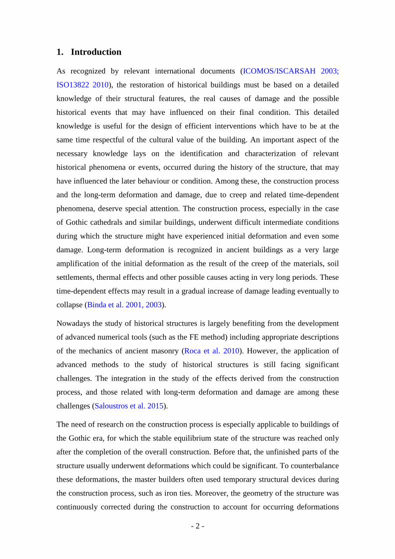
1 Introduction
As recognized by relevant international documents (ICOMOSISCARSAH 2003
ISO13822 2010) the restoration of historical buildings must be based on a detailed
knowledge of their structural features the real causes of damage and the possible
historical events that may have influenced on their final condition This detailed
knowledge is useful for the design of efficient interventions which have to be at the
same time respectful of the cultural value of the building An important aspect of the
necessary knowledge lays on the identification and characterization of relevant
historical phenomena or events occurred during the history of the structure that may
have influenced the later behaviour or condition Among these the construction process
and the long-term deformation and damage due to creep and related time-dependent
phenomena deserve special attention The construction process especially in the case
of Gothic cathedrals and similar buildings underwent difficult intermediate conditions
during which the structure might have experienced initial deformation and even some
damage Long-term deformation is recognized in ancient buildings as a very large
amplification of the initial deformation as the result of the creep of the materials soil
settlements thermal effects and other possible causes acting in very long periods These
time-dependent effects may result in a gradual increase of damage leading eventually to
collapse (Binda et al 2001 2003)
Nowadays the study of historical structures is largely benefiting from the development
of advanced numerical tools (such as the FE method) including appropriate descriptions
of the mechanics of ancient masonry (Roca et al 2010) However the application of
advanced methods to the study of historical structures is still facing significant
challenges The integration in the study of the effects derived from the construction
process and those related with long-term deformation and damage are among these
challenges (Saloustros et al 2015)
The need of research on the construction process is especially applicable to buildings of
the Gothic era for which the stable equilibrium state of the structure was reached only
after the completion of the overall construction Before that the unfinished parts of the
structure usually underwent deformations which could be significant To counterbalance
these deformations the master builders often used temporary structural devices during
the construction process such as iron ties Moreover the geometry of the structure was
continuously corrected during the construction to account for occurring deformations
- 3 -
such as those due to mortar or soil settlements The unbalanced horizontal thrusts
transmitted by the arches and vaults during intermediate construction stages when the
structure was still incomplete might cause difficult equilibrium conditions and large
deformation Therefore temporary devices such as iron ties were extensively used in
Europe to withstand the unbalanced thrusts of the vaults in the lateral naves before the
completion of the central one (Fitchen 1961)
Mallorca Cathedral one of the most impressive Gothic monuments of the
Mediterranean area is a perfect example of the combined consequences of both the
construction process and the time-dependent phenomena in the materials like the long-
term creep behaviour of masonry Numerous structural studies of the cathedral have
been carried out since the beginning of 20th century and until recently (Rubiacuteo 1912
Mark 1982 Roca 2001) An advanced computational model has been utilized lately to
analyse the structure including the effect of the construction process (Clemente 2006
Roca et al 2012 2013) This first attempt to model the construction process
investigated the possibility of erecting the structure without the use of auxiliary
members such as iron ties The analysis showed that without the use of temporary ties
or other auxiliary devices the structure would experience significant damage and large
deformation during the construction
More recently a comprehensive on-site investigation of the building has allowed the
identification of the remains of iron ties used during construction (Bourgeois 2013)
These remains consist of tie ends clamped into the masonry and left there after having
cut and removed the rest of the tie In fact there are two intact ties still visible in the
building which were previously regarded as a latter strengthening but might be the
only left uncut during the construction The use of ties during the construction
however is not known to be mentioned in any available historical document on
Mallorca cathedral
This work focuses on the effect of the use of auxiliary iron ties on the construction
process and current deformation of one typical bay of the cathedral The analysis of this
single macroelement is rather representative since the construction process of the whole
cathedral was characterized by a sequential building of the bays from the presbytery to
the faccedilade (Gonzaacutelez et al 2008)
It is worth noting that the present research is a further stage of a broader long term
study All the conducted studies have contributed to deepen the knowledge of the
- 4 -
present condition and behaviour of a complex and unique building The huge
dimensions the three-nave system with high-rise aisles the spaciousness of the interior
the extreme slenderness of piers and structural members are some of the peculiar
features that make Mallorca Cathedral one of the most ambitious and sophisticated
examples of Gothic architecture
The outline of the paper is as follows Firstly a general overview of wrought iron
members used during the Gothic era is given in order to provide useful information and
to better contextualize the research Secondly a brief description of Mallorca Cathedral
and a summary of principal outcomes from previous studies are presented The
emphasis in this paper is on the historical data available about the construction process
of a single bay together with some possible hypotheses about the building technology
adopted The bay selected for the analysis is the fourth one counted from the presbytery
located close to the false transept Then the results of on-site investigation are detailed
including the survey and mapping of the tie remains within the cathedral The locations
of the ties as well as their dimensions and mechanical properties are defined according
to the results of a photogrammetric survey This information is used to update the FE
model developed by Roca et al (2012 2013) with the aim of modelling the use of
temporary ties during the construction process A sequential FE analysis of the fourth
bay is carried out to understand the structural role of ties in the intermediate stages of
the construction A time-dependent analysis is also carried out to investigate the long-
term effects due to the removal of ties and the creep behaviour of masonry after the
completion of the bay The conclusions of the research are aimed to provide a better
understanding of the complex construction process of a Gothic cathedral and its
influence on the current deformed state of the structure
2 Structural iron elements in Gothic construction
The recognition that iron was largely used in Gothic construction is relatively new
Indeed many authors architects and engineers of the 18th 19th and 20th centuries and
even before (Delorme 1567 Gau 1841 Ruskin 1849) decried the use of iron in the
construction of Gothic monuments for numerous reasons Among them they mentioned
its durability problems causing rusting and stone damage its subjective non-aesthetic
its poor value as a construction material compared to the nobility of stone and its
supposed incompatibility with traditional ways of construction Iron was also
- 5 -
considered by some authors as an ldquoeasyrdquo way to build a trick that should not have been
used for the construction of the great Gothic monuments (Delorme 1567)
The careful studies of Gothic architecture by Viollet-le-Duc (1854) changed
significantly the understanding of the use of iron in Gothic construction Iron was no
more seen as a dangerous material but on the contrary as a useful one that served
completely the goals of this type of construction With the support of well-documented
plans and drawings (Figure 1a) he showed the importance of iron elements as structural
and non-structural devices However and in spite of it he considered Gothic
architecture as essentially lithic stone was the principal structural material while iron
had only a minor role Even if some 20th century authors recognized the use of iron in
Gothic constructions (Acland 1972) it is only at the beginning of the nineties that the
research on Beauvais Cathedral carried out by Taupin (1996) plainly proved the
importance of the presence of iron elements in Gothic construction and their essential
structural roles Successive researches on this subject (LrsquoHeacuteritier et al 2005 2007
Bernardi and Dillmann 2005 Timbert and Dillmann 2010) showed the huge quantity
of structural and non-structural iron elements in several French Gothic buildings
Interdisciplinary studies were carried out based on archaeologic and archaeometric
analyses on-site study to locate all metal elements on the monument documentary
study to assemble all the mentions of metal in the construction accounts and
metallographic analyses to determine the type of material employed and the way it was
worked Integrated methodologies based on slag inclusion analyses were used to
distinguish ironmaking processes (bloomery or indirect) and to determine if artefacts
have the same origin in terms of iron ore reduction system (Dillmann and LrsquoHeacuteritier
2007)
From the aforementioned researches it was proved that iron was used both as a
temporary and a as a long-lasting device and for structural and non-structural purposes
In fact due to its advantageous mechanical properties it was thanks to the use of iron
that Gothic architects and builders could realize their dream of space lightness and
height
Together with other structural elements made of iron (bars in glass stained windows
clamps studs dowels hooks chaining systems) temporary and permanent ties were of
primary importance for numerous Gothic structures (LrsquoHeacuteritier et al 2012) A tie can be
defined as ldquoa piece of metal or wood that maintains the spacing of the truss beams of a
- 6 -
wooden frame or the tilting of two parallel walls or the thrust of an archrdquo (Viollet-le-
Duc 1854) These elements can be divided into two different categories
On the one hand temporary ties that were employed to withstand the horizontal
thrust of the vaulting systems during the construction phases of a monument In effect a
Gothic monument is supposed to be stable at the end of its construction when the
complex system of horizontal and vertical thrusts is properly balanced Therefore
temporary devices had to be designed in order to bear the unbalanced thrusts during the
intermediate stages of the construction Together with the use of centerings that were
expensive and difficult to uninstall Gothic builders developed other temporary tools
like wooden and iron ties (Brunet 1928) The former were embedded inside the
masonry and then cut after the structure had reached a sufficient stability like in
Chartres Amiens and Soissons cathedrals For iron ties hooks and rings allowing the
ties to be removed after the construction process were often used Temporary ties were
also used to prevent disorders after decentering during the settlement of the mortar in
masonry Nevertheless once the construction was finished and the settlement problems
in the masonry seemed to have been stabilized these ties apparently did not present any
advantage for the structure The flows of thrusts could be transmitted by the complex
structural system made of flying arches buttresses and additional weights such as
pinnacles (Viollet-le-Duc 1854 Choisy 1899) Relevant examples are tie-rods in
Amiens Beauvais Soissons and Reims cathedrals that were removed once the structure
had settled after the building process
On the other hand permanent ties were designed to be a fully active part of the structure
even after the completion of the construction Those ties were essentially made of iron
This technique was mainly developed and used in Italy and was also often applied
during consolidation works realized after the construction was completed (Guadet
1907) The use of permanent ties saves lithic material and thus significantly reduces or
even replaces the flying arches and buttresses systems Permanent ties as a way to
strengthen the structure have been also used in the exterior structure to withstand the
horizontal wind forces especially in case of slender buttresses Beauvais Cathedral in
France is an example of the use of such a technique (Dillmann 2011)
The use of ties was widespread during medieval times in Europe Not surprisingly it is
in France cradle of Gothic architecture where it is possible to observe a consequent
number of Gothic monuments with remains of temporary ties The principal nave of
- 7 -
Basilica Saint Marie-Madeleine of Vezelay rebuilt during the 12th century (Figure 1b)
(Lethaby 1906) Reims Cathedral as well as the cathedral Notre-Dame of Amiens
(Figure 1c) are representative examples of the use of temporary ties As for permanent
ties the most representative examples can be found in Italy such as the Basilica of San
Petronio in Bologna the Cathedral of Santa Maria del Fiore in Florence and Milano
Cathedral Other examples can also be found in France like the Cathedral Saint-
Gervais-et-Saint-Protais (Figure 1d)
Finally the ties have been used as later strengthening systems when the thrust of the
arches and vaults was not effectively taken by the system of flying buttresses (Brown
1845) This problem may be due to several different reasons such as under-
dimensioning of masonry elements deformation accumulation due to viscous effects
increase of loading over the arches or vaults or partial destruction of the structural
system In any case these phenomena induced some damage to the structure and ties
were added to fix the problem This is the case for example of Soissons Cathedral
where a complete strengthening system was added to the initial construction (Dillmann
2011) Strengthening ties were added in modern times in numerous French historical
monuments because of alarming deformations and settlements eg Notre-Dame of
Amiens the Great Abbey Church of Abbeville and the Choir of Saint-Julien-Le-Pauvre
in Paris Also the Cathedral of Vitoria Spain was strengthened using rod-ties because
of the insufficient containment of lateral thrusts causing heavy deformation due to
absence of flying buttresses in the original design and their inefficient late addition
(Azkarate et al 2001)
3 Mallorca cathedral collected data
The cathedral of Santa Maria in Palma de Mallorca (Figure 2) is one of the most
emblematic Gothic monuments of the Mediterranean area and especially of Spain The
cathedral was progressively constructed over a period of 300 years from 1306 to 1600
It presents typical features of the so-called Catalan Gothic Style such as high lateral
naves the presence of chapels located between massive buttresses and extremely
slender octagonal piers resulting in a spacious and diaphanous interior space The
cathedral was built with limestone from different local quarries
The cathedral has an overall length of 121 m and a width of 55 m (Figure 3) The
central nave has a length of 77 m the free span of the vaults is 178 m and the height
from the ground to the top of the interior vaults is 44 m The height of lateral naves is
- 8 -
294 m and the span of their vaults is 875 m The piers have an octagonal section with
circumscribed diameter of 16 or 17 m and a height of 227 m to the springing of the
lateral vaults There are a total of seven bays including a false transept with lateral
entrances
Mallorca cathedral was first conceived as a single nave structure of a more moderate
height The construction began in 1300 from East with the construction of the so-called
Trinity Chapel and Royal Chapel which today form the presbytery of the cathedral
According to the most widely accepted interpretation by 1330 it was decided to build
the remaining construction according to a three-nave plan and yet by the mid of 14th
century it was decided to increase the height of the vaults The construction of the main
nave developed during the rest of 14th and 15th centuries with a major interruption
from 1460 to 1570 The West faccedilade of Renaissance style was built from 1594 to
1601 when the cathedral was consecrated The West faccedilade was demolished and
replaced by a new faccedilade by mid-19th century due to a concerning out-of-plumb More
information about the history of the cathedral the existing damage and structural
alterations can be found in previous studies (Roca 2001 Gonzaacutelez et al 2008 Roca et
al 2012 2013 Bourgeois 2013)
Several NDT and MDT techniques were carried out in the past and provided
valuable information about the cathedral (Roca et al 2008) Microscopy and
diffractometry on both mortar and blocks could identify the different types of masonry
corresponding to different construction stages and confirm the hypotheses about the
construction process derived from the historical research (see Section 31) Seismic
tomography and pulse radar were carried out in order to identify the internal
morphology of the structural members and the quality of the materials An integrated
near-surface geophysical survey was carried out both inside and outside the cathedral
perimeter to investigate the subsoil (Peacuterez-Gracia et al 2009) Continuous dynamic
monitoring was considered to characterize the dynamic response of the building under
low amplitude vibrations (Martiacutenez 2007 Elyamani et al 2012)
A five-year monitoring system was installed in the Cathedral in 2003 (Roca and
Gonzaacutelez 2008) Significant deformations were measured in the piers which showed a
certain curvature and lateral displacement especially along the direction transverse to
the nave (Roca et al 2012 2013) The bays lateral deformations are very variable
without following a similar trend ie with random deformation in piers both in terms of
direction (inward or outward to the nave) and magnitude The maximum lateral
- 9 -
displacement measured in piers ranges from 002 m up to in a single case 026 m with
an average (in absolute value) of 013 m corresponding to a ratio of 1175 with respect
to the height The piers placed between the third and fourth bay (the bays are numbered
starting from the apse) showed at their top a symmetrical component of the horizontal
displacement of 0095 m with a cumulative rate of 01 mmyear
31 Construction process
Even if historical data on the construction process of Mallorca Cathedral are scarce
it has been possible to find documents on the construction of its fourth bay (Roca et al
2013) which lasted from 1391 to 1460 (Figure 4) First the perimeter structure
including the lateral chapels walls and buttresses were built Then the piers were added
followed by the construction of one of the lateral vaults the so-called Epistle vault
(located towards the South) then the second one the Gospel vault (located towards the
North) and finally the vault of the main nave The construction of each vault took
around one year Because of some interruptions in the work the period of time between
the completion of the first lateral vault and the one of the central nave was five years
meaning that the thrust of the lateral naves acted on the interior piers without the
counteracting effect of the central vaults for a long time
Several hypotheses concerning the temporary stabilization of the structure during
the construction process have been proposed (Gonzaacutelez et al 2008) First the non-
finished structure may have been able to withstand the thrust itself without any auxiliary
devices thanks to its small tensile strength Tensile strength is usually limited in
masonry structures and it is more likely to vanish in the medium or long-terms due to
environmental cyclic actions or decay Nevertheless in the early stage of construction
this small tensile strength might have been enough to overcome the lateral thrust This
possibility has been examined in depth in some previous studies (Clemente 2006 Roca
et al 2012 2013) A second hypothesis is that the centering used for the lateral vaults
may have been active during the construction process of the bay until the central nave
was finished Such solution would have led to difficult equilibrium conditions during
the final removal of centering causing randomly unbalanced inward or outward thrust
Finally other types of temporary devices such as iron or timber ties across the lateral
arches or struts across the central one may have been used to resist the thrust of the
lateral vaults The possible use of iron ties is examined in this study since their remains
can be recognized on the structure nowadays as it will be explained in Section 32
- 10 -
Such solution seems more conservative and realistic than the first or second hypotheses
mentioned The iron ties presumably installed before the construction of the aisles can
resist the thrust transmitted by the lateral vaults and limit the deformation of the pier
towards the unbuilt central nave After the completion of the central nave the iron ties
would experience a certain unloading due to the contrasting effect of the new outward
thrusts coming from the central vault For this reason it was possible to remove the ties
after the completion of the central nave In spite of the use of ties the construction
process still involved some uncertainty and risks because even after the completion of
the central vaults the ties might retain significant forces that would be suddenly
transferred to the structure when they were cut and removed
Even if it will not be addressed in this study another interesting problem is the
longitudinal stability of the structure during the construction process In effect during
the intermediate construction stages in the longitudinal direction the piers had to
withstand the unbalanced longitudinal thrusts of both the lateral and central vaults The
main body of the cathedral was constructed bay after bay over a long period of time and
this may have led to significant deformations in the longitudinal direction The
historical information available discards the possibility of a previous construction of all
the clerestory arches as elements stabilizing longitudinally the bays at intermediate
stages Therefore longitudinal temporary members like iron ties and timber struts
might have been also used as proposed by some studies about the construction of
medieval cathedrals (Viollet-le-Duc 1854 Fitchen 1961)
32 On-site evidence of the use of auxiliary ties in the construction process
As it has been observed in previous studies (Clemente 2006 Roca et al 2012
2013) the use of auxiliary ties during the construction process of Mallorca Cathedral
cannot be disregarded Darker spots have been detected on the surface of the masonry
in the lower part of the arches at two different heights These spots seem to exist on
each side of the lateral bay (Figure 5) Once the corresponding two spots of each side
are linked together with fictive lines a certain parallelism appears between the lines
The presence of two remaining ties for two of the bays (Figure 5a and Figure 5b) has
also been noticed There is no information on whether these remaining ties were placed
during the construction or were installed later as a strengthening device From these
preliminary observations a thorough on-site inspection has been carried out to detect
- 11 -
evidences on the past use of ties in the Cathedral The considered approach includes on-
site inspection (Figures 5 6 and 7) and photogrammetry (Figure 8)
Firstly dark spots corresponding of cut tie ends have been identified in all the bays of
the cathedral (Figure 6 and Figure 7) They are present in the northern lateral nave
where the remaining ties are but also in the southern nave Therefore they appear to be
a characteristic feature of the bays of the cathedral For most of the bays two separate
spots have been detected at the base of the arches Uncertainties still remain for the bays
1-2 and 2-3 (Figure 6 and Figure 7) and thus a more accurate investigation should be
carried out at these locations to understand if the existing spots correspond to one or two
ties One can notice the consistency of the spotsrsquo height since they always appear at
similar locations Concerning the upper spots they are located at the same level of the
two remaining ties The photogrammetric study of the south lateral nave (Figure 8)
leads to the same conclusions and thus corroborates the temporary ties hypothesis By
zooming on the spots it is possible to observe their real shape concerning the upper
ones some of the pictures reveal that they are in fact remaining metallic hooks (Figure
5c and Figure 5d) iron devices extensively used during medieval times The lower spots
seem to be sawn rectangular metallic elements (Figure 5e and Figure 5a) Some damage
around these spots has been also observed (Figure 5f) It seems that the stone at these
locations was pulled off which may be explained by the presence of ties working in
tension leading to a concentration of tensile stresses at the location of their anchorages
with the masonry Another explanation may be that the material was damaged at such
locations during the removal of the iron ties A further explanation can be damage due
to the corrosion of the remaining iron
These features seem to be a proof of the possible use of structural iron ties during the
lifetime of the cathedral Moreover the similarities between these elements and the ones
previously observed in Amiens Cathedral in France cannot be disregarded and should
be considered to reinforce the hypothesis of the use of temporary ties during the
construction process of Mallorca Cathedral
The on-site combined study provides a good approximation of the height of the ties
remains and a rough estimation of the section of the missing ties In particular it has
been possible to evaluate the height of the ties of the fourth bay whose structural
analysis is reported in Section 4 Accordingly the connection of the first set of ties with
the masonry has been considered to be located at 040 m from the top of the capital of
the pier to the centre of the lower tie section (ie at 78 of the total height of the aisle
- 12 -
the latter considered equal to 294 meters) whereas the connection of the second set of
ties with the masonry has been considered to be located at 206 m from the top of the
capital of the pier to the centre of the upper tie section (ie at 84 of the total height of
the aisle) Those heights have been assumed in the structural analysis for both sides of
the bay and the ties are assumed perfectly horizontal In addition their total cross-
section is assumed to be equal to 25 cmsup2 which is in good accordance with the average
value of the cross-section measured (27 cmsup2) after the photogrammetric study It is
worth mentioning that such calculated cross section is comparable to those of existing in
other Gothic churches For instance the cross sections of the ties of Milano Cathedral
range between 35 cmsup2 and 55 cmsup2 (Vasic 2013)
4 Structural analysis
Some structural analyses were previously carried out for the 4th bay of Mallorca
Cathedral The initial studies (Roca 2001) did not take into account the construction
process the geometric nonlinearity and the long-term creep behaviour of masonry
leading to qualitative results concerning the displacements and the deformation endured
by the structure In particular the deformations obtained by FE analysis were too small
if compared with the real ones measured during the geometrical survey of the cathedral
Later studies (Clemente 2006 Roca et al 2012 2013) considered a sequential FE
analysis of the construction process of the bay The analysis was divided into three
stages a first stage involving the construction of the lower part of the bay (lower part of
the buttresses lower part of the piers and the lateral vaults) a second stage involving
the completion of the bay (upper-part of the buttresses and piers together with the vault
of the central nave) and a third stage taking into account the long-term creep behaviour
of the masonry The deformations obtained in these studies were closer to the real ones
These analyses were carried out with no auxiliary device for the stability utilized during
the first stage of the construction and investigated if the structure would have been able
to overcome the instability during the construction phases thanks to the contribution of
the tensile strength of the masonry Nevertheless the authors of these previous works
mentioned that the use of provisional devices during the construction process of the bay
could not be disregarded even if they did not study in depth such a scenario
In this paper a new structural analysis is presented based on the consideration of the
use of temporary iron ties during the construction of the 4th bay The FE model already
developed by Roca et al (2012 2013) has been improved to assess the consequences of
- 13 -
the use of auxiliary devices on the construction process stages as well as their influence
on the deformation of the structure taking into account the long-term creep behaviour
of the masonry The pre-post processor GID (CIMNE 2002) and the FE software
COMET (Cervera et al 2002) both developed at the CIMNE have been utilized for
this study These softwares have been also applied to recent studies of masonry
structures (Pelagrave 2009 Pelagrave et al 2013)
41 Model description
The FE model of the 4th bay developed by Roca et al (2012 2013) has been modified in
this work to include the iron ties in the structure discretization The updated model is
composed by 14689 nodes and 49979 elements including tetrahedral elements to
represent the solid masonry members and linear two node truss elements to represent
the ties Due to the assumed geometrical symmetry only a quarter of the bay is
modelled Appropriate boundary conditions have been considered to take into account
the effect of the rest of the bay as well as the longitudinal confinement exerted by the
adjacent bays
The total cross-section of the ties based on the photogrammetric survey is assumed to
be equal to 25 cmsup2 leading to a section to implement of 125 cmsup2 (only half of each tie
is modelled in a quarter of the bay) The ties are considered elastic since they are made
of relatively resistant and ductile iron compared to the masonry The solid elements
surrounding the nodes connecting the ends of the 2D ties are defined as elastic in order
to avoid damage due to excessive concentrations of stresses and unrealistic local
failures In the real building these ends are probably linked to timber or iron anchor
devices embedded in the structural members and able to distribute the forces over
sufficiently large volumes of masonry In any case a detailed inspection of the
anchoring detail would be certainly convenient
Additional weights like pinnacles infill and stone pyramids over the lateral vaults have
not been modelled but their weight has been considered in calculations
A small strainslarge displacements formulation is considered in the FE model to take
into account the geometrical non-linearity effects The viscoelasticity model coupled
with a damage model firstly proposed by Cervera et al (1995 2003) and Faria et al
(1998) and adapted to masonry material by Roca et al (2012 2013) has been also
utilized for the present calculations The constitutive equation can be written as follows
- 14 -
( )( ) ( )( )1 1e v e vd d+ + + minus minus minus= minus + + minus +σ σ σ σ σ (1)
where σ is the stress tensor and σ is the effective stress tensor related to strains ε
under elastic regimen The damage level experienced by the material can be described
by means of two scalar parameters one for cracking in tension (d-) and another for
crushing in compression (d+) The value of the damage indexes varies between 0 for
intact material and 1 for completely damaged material The tensor vσ denotes the part
of the effective (undamaged) stress tensor that is related to viscosity A split of the
effective stress tensor is carried out according to Cervera et al (1995 2003) and Faria et
al (1998) in order to distinguish tensile and compressive components +σ and minusσ
leading to
( ) ( )e v e v+ minus + + minus minus= + = + + +σ σ σ σ σ σ σ (2)
The time-dependent deformation accumulation due to creep is described by a
rheological model based on the definition of two input parameters the participation
ratio ξ and the retardation time θ The viscous model can be expressed by the following
equation
vvξ
ϑ= +
σC ε σ (3)
in which C is the isotropic linear-elastic constitutive tensor Introducing the viscous
strain vε it can be written
( )v vξ= minusσ C ε ε (4)
Substituting (4) into (3) the evolution law for the viscous strain is
( )1v vϑ= minusε ε ε (5)
The specific role of the participation ratio ξ and the retardation time θ will be discussed
in Section 422 More information about the constitutive model the input parameters
and the integration of the internal variables can be found in Roca et al (2012 2013)
The material parameters that have been used in the FE summarized in Table 1 are the
same already utilized for the analyses presented in Roca et al (2012 2013) Note that
the tensile strength of the masonry has been taken equal to 5 of the compressive
- 15 -
strength The Youngrsquos moduli adopted for the different masonry elements have been
taken from a previous study by Martiacutenez (2007)
The properties of wrought iron have been decided using available literature for
historical iron construction (Leutwiler 1917 Whitey and Aston 1926 DB Netz AG
2002 Schweizerische Bundesbahnen 2002 Network Rail 2001 Juhin 2005
Mechanical Engineering 2009) Reference values for Youngrsquos modulus range between
200 GPa and 243 GPa whereas for tensile strength range between 250 MPa and 390
MPa Recent studies aimed at characterizing the material of the ties of Milan Cathedral
showed that wrought iron was employed for the construction Tensile tests on 9 samples
provided a Youngrsquos modulus of 205 GPa and a tensile strength of 300 MPa (Vasic
2013 Guidobaldi et al 2014)
42 Sequential analysis of the construction process
On the basis of the on-site survey described in Section 32 two potential locations
for the ties are assumed an upper one located at 206 m from the top of the piers capital
and a lower one located at 040 m from this reference height Nevertheless even if
visual evidences on the existence of tie remains have been found for each bay only
suppositions can be done about their real utilization and the duration of their action on
the structure In this study four different tie configurations are considered during the
sequential analysis of the construction process utilization of the upper tie only
utilization of the lower tie only utilization of both the ties (upper and lower) no
utilization of ties
A sequential FE analysis similar to the one proposed by Roca et al (2012 2013) is
considered to simulate the construction process of the 4th bay The main difference is
that the analysis is divided in this work into 4 different stages The first stage
corresponds to the beginning of the construction During this stage only the members
corresponding to the lower part of the bay are activated in the analysis the lower part of
the buttress the pier the lateral vault the lower part of the clerestory wall and the ties
(Figure 9a) The inclusion of one or two ties in the FE model according to the
configuration of the auxiliary system assumed leads to a reduction of the outwards
deformation of the pier compared to the case without ties After this stage the FE mesh
of the upper-part of the structure is corrected before its activation Because the lower
part of the structure has undergone deformations during the first stage of the analysis
the coordinates of the nodes of the upper part of the FE mesh (deactivated) have to be
- 16 -
corrected in order to represent realistically the carrying on of the construction over the
already deformed lower part This method already used by Roca et al (2013) is based
on the two following assumptions maintenance of the direction of the vertical and
horizontal lines and negligible total elongation of the line at the boundary between parts
corresponding to different construction phases The correction to be applied to the nodes
of the upper part of the FE model is given by the average displacement vector of the
nodes in the boundary of the two phases after the first construction stage After this
correction has been made the second stage corresponding to the construction of the rest
of the bay is analysed During this stage the bay is completed In addition to the sets of
elements previously activated the following ones are added to the analysis the upper
buttress the upper clerestory the flying arches the diaphragmatic transverse arch with
its overload the vault of the main nave and its filling (Figure 9b) Then the removal of
the ties is simulated (third stage) by deactivating them and excluding them from the FE
model (Figure 9c) This sudden removal reproducing a possible cut of the ties after the
completion of the bay leads to an increase of deformations at the top of the pier
Finally the long-term creep behaviour of the structure is considered (fourth stage)
After the deactivation of the ties time starts elapsing and the accumulation of
deformation and damage under constant loading is evaluated according to the viscous
and damage model assumed for masonry The time-dependent analysis has been carried
out on the case including a single tie
421 Construction process and ties removal
After the first construction stage in which only the aisle is built the pier receives at
its top the thrust transmitted by the vault Since the central nave is not yet built such
thrust is not balanced by the thrust coming from the central vault The magnitude of the
horizontal displacement at the top of the pier reaches a maximum if no ties are present
in the aisles As expected the presence of one or two provisional ties reduces this
deformation
As mentioned three different FE analyses have been carried out in this work
considering respectively the presence of the upper tie the lower tie or both ties
(Bourgeois 2013) Table 2 summarizes the values of the horizontal displacements
found at the top of the pier after each stage for different ties configurations The results
are compared with those obtained by Roca et al (2012 2013) for the case without ties
- 17 -
From the comparison of different results it is possible to make several observations
concerning the influence of the use of temporary ties during the construction process
During the first two steps the presence of the ties reduces the horizontal displacement u
of the pier the insertion of the ties within the model limits the deformations caused by
the horizontal thrust of the lateral vault Figure 10 gives the ratio (u0-u)u0 denoting the
efficiency of the restraining effect for each configuration of ties being u0 the horizontal
displacement for the analysis with no ties The reported values are percentages of
decrease of the displacement at the pier top for each system and constructions stage
with reference to the case without ties As expected the displacement decrease is
maximum (766) for the case with two ties and after the second stage Once the
construction of the bay is completed the sudden removal of the ties causes a significant
increase of the horizontal displacement Nevertheless at the end of the third stage the
horizontal displacements of the pier are still less than the ones found in the
configuration with no ties with a reduction ranging from 211 for the upper tie case to
285 for the two ties case The evolution of the horizontal displacement at the top of
the pier follows the same tendency for the three different tie configurations
During the first stage the ties contribute significantly to restrain the lateral drift of the
pier (Table 2) However and as should be expected from its more adequate location the
lower tie is more efficient than the upper one As a result the lateral displacements
experienced by the pier in the cases with two ties or with only the lower one are very
similar especially after the second stage (4 mm and 5 mm) The displacement is
significantly larger when only the upper tie is considered (8 mm) After the removal of
the ties (third stage) the lateral displacement of the pier is very similar in the three cases
(between 12 mm and 14 mm) and only slightly smaller than the displacement
experienced in the case with no ties (17 mm) Therefore the ties are helpful in limiting
the difficulties and deformation experienced during the first stage of the construction
but do not have a very significant influence after their removal on the final
deformation of the structure
According to the analysis the tie experiences meaningful tensile stresses due to the
horizontal thrust of the lateral vault Table 3 summarizes the values of the tensile forces
and stresses for different construction stages and ties configurations The maximum
tensile stress of 972 MPa appears at the first stage in the case with only lower tie This
- 18 -
stress is far smaller than the tensile strength found for iron in the literature (see Section
41) meaning that the ties are not likely to reach the elastic threshold of the material
Figure 11 shows the tensile damage patterns obtained at each construction stage for the
three different configurations of ties The distribution of damage is rather similar in the
three cases during the sequential analysis The damage at the top outer part of the pier is
properly prevented by the action of ties especially in the two ties configuration On the
other hand the upper-tie configuration leads to the minimum extent of damage within
the extrados of the aisle vault
Figure 12 and Figure 13 show a direct comparison between the tensile damage
distributions respectively after the first and third stages in the configuration without
ties and with the sole lower tie In the case without ties most of the damage is
concentrated at the top outer part of the pier due to the unbalanced thrust transmitted by
the vault of the aisle after the first stage (Figure 13a) After the first stage damage can
be found also at the key of the vault of the aisle and under the false window The
aforementioned damage does not spread further during the construction stage After the
completion of the third stage some damage appears in the upper flying arch and in a
lower extent also in the vault of the central nave (Figure 13b)
The tensile damage at the top outer part of the pier is minor thanks to the structural
action of the ties On the other hand the damage within the vault of the aisle is more
distributed than in the case without ties Also it is not symmetric and appears mainly
concentrated in two zones (Figure 12b and Figure 13b) The damage in the aisle does
not spread further after the second and third construction stages due to the combined
effect of the ties and the construction of the central nave
422 Long-term creep behaviour after the removal of the ties
As a further step towards the study of the deformational response of the structure a
time-dependent analysis has been carried out involving the simulation of the effect of
long-term creep on the structure This analysis has been carried out on the case with a
single tie used per bay in the lower position during the construction
The creep behaviour of masonry has been modelled by the viscoelastic model
coupled with a damage model proposed by Roca et al (2012 2013) and briefly
summarized in Section 41 Two parameters inherent to this model must be defined the
participation ratio ξ and the retardation time θ The former sets the amount of material
- 19 -
stiffness susceptible to creep (Equations 34) The latter parameter sets the rate of
viscous strains (Equation 5) and influences the time scale of the analysis The values
assumed for ξ and θ set the curves obtained in terms of horizontal displacement at the
top of the pier versus time Both parameters have been adjusted by comparison with the
displacements measured during the monitoring programme mentioned in Section 3 that
took place from September 2003 to September 2008 (Roca and Gonzaacutelez 2008) These
dates correspond respectively to the years 543 and 548 after the completion of the bay
The monitoring system measured a symmetrical component of the horizontal
displacement at the top of the pier equal to 0095 m and a deformation rate equal to 01
mmyear at this location for the same period of time (Roca et al 2012)
The main purpose of the numerical analysis was to find an absolute displacement at the
top of the pier close to the one measured in reality for the same period of time In
addition a direct comparison was carried out between the deformation rate measured on
site and that calculated by the model For this purpose a parametric analysis was
necessary to set in the model the correct values of the parameters ξ and θ In fact
among all the possible combinations only one couple of values provides both the
displacement and the deformation rate matching the values recorded during the
monitoring period
The numerical curves presenting the horizontal displacements at the top of the pier in
function of time are given on Figure 14a for both the case with lower tie and without
tie The structure seems to be stable after a smaller period of time for the participation
ratios of 0925 and 0875 and becomes unstable after a longer period of time in the case
of a participation ratio equal to 0975 Comparing the results obtained it is observed
that the bay with the lower tie undergoes less deformation during the elapsing period
than the one without tie thanks to the initial utilization of temporary tensile resistant
members This observation is true for every participation ratio considered The
percentage of reduction of displacement due to tie effect computed for the 543 ndash 548
years is 64 for ξ = 0975 84 for ξ = 0925 and 203 for ξ = 0875 Therefore the
use of ties has also a lasting effect and influence on the long-term deformational
response of the structure However this effect does not change substantially the
observed deformation trends and their influence on the stability of the structure
As shown in Figure 14b the numerical results of the FE model with lower tie match the
experimental data both in terms of horizontal displacement and deformation rate if a
- 20 -
participation ratio of 0925 and a retardation time of θ = 30 years are assumed Only a
really high participation ratio presently equal to 0975 leads to structure instability In
the lower tie configuration this failure should occur around 1240 years after the
completion of the structure Nevertheless such a high participation ratio leads for the
543 ndash 548 years to a horizontal displacement of 0157 m and to a deformation rate of
035 mmyear which are in complete disagreement with the data collected on-site
Therefore this scenario should be disregarded As for a lower participation ratio of
0875 even if the structure is found stable after 1000 years (the horizontal displacement
is constant and equal to 008 m from this year) the computed horizontal displacement
for the 543 ndash 548 years is 0064 m and the deformation rate is 005 mmyear which are
too low compared to the ones obtained from the monitoring On the other hand an
almost perfect matching between the monitored data and the numerical analysis results
is obtained for a participation ratio of 0925 In that case the horizontal displacement at
the top of the pier tends to be stabilized after a rather long period of time In effect it
still increases 1500 years after the completion of the bay for which it reaches the value
of about 0175 m
It is worth noting that the parameters of the model describing the time dependent
behaviour ie the participation ratio ξ and the retardation time θ are of great
importance for FE numerical simulations and must be carefully implemented The
viscous model adopted is sufficiently simple since it requires the calibration of only two
parameters to fully describe the creep behaviour of the material This feature of the
model makes it suitable especially for practical applications In this study as well as in
the previous studies by Roca et al (2012 2013) the participation ratio and the
retardation time were estimated on the basis of the available five year-monitoring data
However a long-term monitoring activity of the cathedral may provide more accurate
data to further improve the description of the time-dependent response
Finally Figure 15 shows the deformed shape and the tensile damage contour at the end
of the time-dependent analysis with geometric nonlinearity for a participation factor of
0925 The tie is not visible in the figure since it has been deactivated after the third
stage of the sequential analysis The damage is mainly concentrated in the aisle vault
under the false window at the anchorages of the already removed ties in the flying arch
and diaphragmatic arch It can be noticed the negligible amount of damage at the top of
the pier Compared to the condition experienced after construction additional damage
appears mainly in the lateral vault
- 21 -
5 Conclusions
The present work has investigated the role of iron ties used as auxiliary devices during
the construction of Gothic cathedrals The study has been carried out by analysing the
structural effect of ties used in the construction of Mallorca cathedral and their possible
long-term influence on the deformational response of the building
A recent inspection in Mallorca cathedral has allowed the identification of the remains
of iron ties utilized during the construction and later removed from the structure The
remains consist of tie ends embedded within the masonry and left there after the cutting
and removal of the ties The ties were used to overcome the difficult equilibrium
condition experienced during an intermediate construction of each bay when the lateral
vaults were already built but not yet the central one
A FE sequential analysis has been carried out to simulate the construction process
taking into account the use and later removal of the ties The analysis has been
performed by means of a numerical model combining material non-linearity though a
continuum damage model with geometrical nonlinearity The analysis has allowed the
quantification of the effect of the ties which are effective in balancing the thrust of the
lateral vault and restraining the lateral drift experienced by the pillars However the
lateral drift of the piers is still appreciable due to the elongation experienced by the ties
The use of ties modifies in a significant way the distribution of initial damage in the
structure
A time-dependent analysis based on a viscoelasticity model coupled with damage has
been carried out to study the increase of the deformation in the long-term The
parameters of the viscoelasticity model have been adjusted based on the results of a
recent monitoring programme It has been observed that the use of temporary ties
during the construction has a lasting effect as a measurable reduction of the long-term
lateral displacements experienced by the piers The use of ties during the construction
process also allows a significant modification of the crack pattern in the piers and
vaults Due to the tie cracking almost disappeared in the pier but increased significantly
in the arches and vaults
6 Acknowledgments
This research has received the financial support from the Ministerio de Educacioacuten y
Ciencia of the Spanish Government and the ERDF (European Regional Development
- 22 -
Fund) through the research project MICROPAR (Identification of mechanical and
strength parameters of structural masonry by experimental methods and numerical
micro-modelling ref num BIA2012-32234)
7 References
Acland James H 1972 Medieval structure the gothic vault Toronto University of Toronto
Press
Azkarate A Caacutemara L Lasagabaster J I Latorre P 2001 El Plan Director para la
restauracioacuten de la Catedral de Santa Mariacutea de Vitoria-Gasteiz (in Spanish) In I Congreso
Europeo de Restauracioacuten de Catedrales Goacuteticas 561-596 Diputacioacuten Foral de Aacutelava
Vitoria-Gasteiz Spain
Bernardi P and P Dillmann 2005 Stone skeleton or iron skeleton The provision and use of
metal in the construction of the Papal Palace at Avignon in the 14th century De Re Metallica
The uses of metal in the Middle Ages London Ashgate 297-315
Bourgeois J 2013 Simulation of the effect of auxiliary ties used in the construction of
Mallorca Cathedral SAHC master thesis Technical University of Catalonia Barcelona
Spain
Binda L Saisi A Messina S and Tringali S 2001 Mechanical Damage Due to Long Term
Behaviour of Multiple Leaf Pillars in Sicilian Churches In Proceedings of III Int Seminar
Historical Constructions 2001 Possibilities of Numerical and Experimental Techniques eds
Lourenccedilo P Roca P 707-718 Guimaratildees Portugal
Binda L Anzani A and Saisi A 2003 Failure Due to Long Term Behaviour of Heavy
Structures the Pavia Civic Tower and the Noto Cathedral In Proocedings of 8th Int Conf on
STREMAH 2003 Struct Studies Repairs and Maintenance of Heritage Architecture 99-108
Halkidiki Greece
Brown Richard 1845 Sacred architecture its rise progress and present state London
Fisher Son amp Co
Brunet E 1928 La restauration de la catheacutedrale de Soissons Bulletin monumental 5765-99
Cervera M Oliver J and Faria R 1995 Seismic evaluation of concrete dams via continuum
damage models Earthquake Eng Struct D 24 91225-45
Cervera M 2003 Viscoelasticity and rate-dependent continuum damage models Monography
79 Barcelona CIMNE Technical University of Catalonia Barcelona Spain
- 23 -
Cervera M Agelet de Saracibar C and Chiumenti M 2002 COMET COupled MEchanical
and thermal analysis ndash data input manual version 50 Technical report IT-308 CIMNE
Technical University of Catalonia Barcelona Spain
Choisy A 1899 Histoire de lrsquoarchitecture Paris Gauthier-Villars Imprimeur-Libraire 2 316-
337
Clemente R 2006 Anaacutelisis estructural de edificios histoacutericos mediante modelos localizados de
fisuracioacuten PhD thesis Technical University of Catalonia Barcelona Spain
DB Netz AG 2002 Ril 805 Tragsicherheit bestehender Bruumlckenbauwerke Germany
Dillmann P and LrsquoHeacuteritier M 2007 Slag Inclusion Analyses for Studying Ferrous Alloys
Employed in French Medieval Buildings Supply of Materials and Diffusion of Smelting
Processes Journal of Archaeological Science 341810-23
Dillmann P 2011 From Soissons to Beauvais the use of iron in some French cathedrals In
The Archaeometallurgy of Iron e Recent Developments in Archaeological and Scientific
Research eds Hosek J Cleere Henry Mihok L 173-196 Prague Czech Republic
Delorme P 1567 Premier tome de lrsquoarchitecture Paris F Morel
Elyamani A Caselles JO Clapes J and Roca P 2012 Assessment of Dynamic Behavior of
Mallorca Cathedral In Structural Analysis of Historical Constructions Proceedings of the
International Conference on Structural Analysis of Historical Constructions SAHC 2012 ed
Jasieńko J 2376-2384 Wroclaw Poland
Faria R Oliver J and Cervera M 1998 A strain-based plastic viscous-damage model for
massive concrete structures Int J Solids Struct 351533-58
Fitchen John 1961 The construction of Gothic cathedrals a study of medieval vault erection
Oxford Clarendon Press
Gau M 1841 De lemploi du fer comme moyen de consolidation dans les monuments
historiques In Revue geacuteneacuterale de larchitecture et des travaux publiques 221
GID the personal pre and post-processor 2002 CIMNE Technical University of Catalonia
Barcelona Spain
Gonzaacutelez R Caballeacute F Domengue J Vendrell M Giraacuteldez P Roca P and Gonzaacutelez JL
2008 Construction process damage and structural analysis ndash Two case studies In Structural
Analysis of Historic Construction Preserving Safety and Significance Proceedings of the VI
International Conference on Structural Analysis of Historic Construction SAHC08 eds
DrsquoAyala D Fodde E 643ndash651 Bath United Kingdom
- 24 -
Guadet J 1909 Les eacuteleacutements de la composition dans les eacutedifices dusage public In Eleacutements et
theacuteories de larchitecture Paris Librairie de la construction moderne
Guidobaldi M Vasic M Gentile C and Poggi C 2014 Frequency splitting in the tie-rods of
the Cathedral of Milan In Proceedings of the 9th International Conference on Structural
Dynamics EURODYN 2014 eds Cunha A Caetano E Ribiero P Muumlller G 1477-1483
Porto Portugal
ISCARSAH Committee ICOMOS 2003 Recommendations for the Analysis Conservation and
Structural Restoration of Architectural Heritage
ISOTC98 ISOFDIS 13822 2010 Bases for design of structures ndash assessment of existing
structures Genegraveve
Juhin A 2005 Structure meacutetallographique et comportement meacutecanique des tirants de fer du
donjon du chacircteau de Vincennes Master thesis Universities of Paris 6 Pierre et Marie Curie
and Paris-Sud 11 Paris France
LrsquoHeacuteritier M Juhin A Dillmann P Aranda R and Benoit P 2005 Utilisation des alliages
ferreux dans la construction monumentale du Moyen Age Etat des lieux de lrsquoavanceacutee des
eacutetudes meacutetallographiques et archeacuteomeacutetriques ArcheacuteoSciences 29117-132
LHeritier M 2007a Lutilisation du fer dans larchitecture gothique les cas de Troyes et de
Rouen PhD thesis Universiteacute Pantheacuteon-Sorbonne - Paris I Paris France
LrsquoHeritier M Dillmann P Timbert A and Bernardi P 2012 The Role of Iron Armatures in
Gothic Constructions Reinforcement Consolidation or Commissionerrsquos Choice In
Proceedings of the 4th International Congress on Construction History 557-564 Paris
France
Lethaby W R 1906 Westminster Abbey amp the Kings Craftsmen a study of mediaeligval
building London Duckworth amp Co
Leutwiler O A 1917 Elements of machine design New York McGraw-Hill Book Company
inc
Mark R 1984 Experiments in Gothic Cathedrals Cambridge MIT Press
Martiacutenez G 2007 Vulnerabilidad sismica para edificios histoacutericos de obra de faacutebrica de
mediana y gran luz PhD thesis Technical University of Catalonia Barcelona Spain
Mechanical Engineering 2009 LAXMI Publications (P) LTD
Network Rail 2001 RTCEC025 Railtrack Line Code of Practice The Structural Assessment
of Underbridges United Kingdom Railtrack
- 25 -
Pelagrave L 2009 Continuum Damage Model for Nonlinear Analysis of Masonry Structures PhD
thesis Technical University of Catalonia Spain University of Ferrara Italy
Pelagrave L Cervera M and Roca P 2013 An orthotropic damage model for the analysis of
masonry structures Constr Build Mater 41957-967
Peacuterez-Gracia V Caselles JO Clapeacutes J Osorio R Martiacutenez G and Canas JA 2009
Integrated near-surface geophysical survey of the Cathedral of Mallorca Journal of
Archaeological Science 361289ndash1299
Roca P 2001 Studies on the structure of Gothic Cathedrals In Historical Constructions 2001
Possibilities of numerical and experimental techniques Proceedings of the 3rd International
Seminar eds Lourenccedilo PB Roca P 71-90 Guimaratildees Portugal
Roca P and Gonzaacutelez JL 2008 Estudio diagnoacutestico y peritacioacuten y en su caso planteamiento
de actuaciones sobre el comportamiento constructivo-estructural de la catedral de Santa
Mariacutea en la ciudad de Palma isla de Mallorca (Baleares) Fase segunda (in Spanish)
Barcelona Technical University of Catalonia
Roca P Clapeacutes J Caselles O Vendrell M Giraacuteldez P and Saacutenchez-Beitia S 2008
Contribution of inspection techniques to the assessment of historical structures In
Proceedings of the International RILEM SACoMaTiS Conference Varenna Italy
Roca P Cervera M Gariup G and Pelagrave L 2010 Structural Analysis of Masonry Historical
Constructions Classical and Advanced Approaches Arch Comput Method Eng 17299ndash325
Roca P Cervera M Pelagrave L Clemente R and Chiumenti M 2012 Viscoelasticity and
Damage Model for Creep Behavior of Historical Masonry Structures The Open Civil
Engineering Journal 6 (Suppl 1-M7)188-199
Roca P Cervera M Pelagrave L Clemente R and Chiumenti M 2013 Continuum FE models
for the analysis of Mallorca Cathedral Engineering Structures 46653-670
Rubioacute J 1912 Conferencia acerca de los conceptos orgaacutenicos mecaacutenicos y constructivos de la
catedral de Mallorca Barcelona Anuario de la Asociacioacuten de Arquitectos de Cataluntildea
Ruskin J 1849 The seven lamps of architecture London The Waverley Book Company
Saloustros S Pelagrave L Roca P and Portal J 2015 Numerical analysis of structural damage in
the church of the Poblet monastery Engineering Failure Analysis doi
101016jengfailanal201410015
Schweizerische Bundesbahnen 2002 SBB Weisung I-AM 0802 Bern Baudirektion
Taupin J-L 1996 Le fer dans les catheacutedrales Monumental 1318-27
- 26 -
Timbert A and Dillmann P 2010 Le squelette de fer des catheacutedrales gothiques Paris Citeacute
des Sciences
Vasic M Coronelli D and Poggi C 2013 A Multidisciplinary approach for the assessment
of great historical structures ties of Duomo di Milano In Proceedings of International
Conference Built Heritage 2013 Milan Italy
Viollet-Le-Duc E 1854 Dictionnaire Raisonneacute de lrsquoArchitecture Franccedilaise du XIe au XVIe
siegravecle Paris B Rance Editeur
Whitey MO and Aston J 1926 Johnsonrsquos Materials of Construction Hoboken John Wiley
amp Sons
8 Tables Captions
Table 1 Materials properties implemented in the FE model
Table 2 Horizontal displacements at the top of the pier after each stage of the FE
simulation of the construction process for different ties configurations
Table 3 Tensile forces and stresses after each stage of the FE simulation of the
construction process for different ties configurations
9 Figures Captions
Figure 1 Examples of ties used during the construction process of numerous medieval
monuments Connection of a typical iron hook with the rest of the structure (a) Basilica
Sainte Marie-Madeleine of Vezelay (b) Cathedral Notre-Dame of Amiens (c)
Cathedral Saint-Gervais-et-Saint-Protais of Soissons (d) Sources (a) Viollet-le-Duc
(1854) (b) Timbert and Dillmann (2010) (c) commonswikimediaorg and (d) Timbert
and Dillmann (2010)
Figure 2 Mallorca Cathedral external view (a) and view from the interior (b)
Figure 3 Transversal (a) and longitudinal (b) sections of Mallorca Cathedral
Figure 4 Construction stages of the fourth bay (Roca et al 2013)
Figure 5 Visual evidences of the remains of temporary iron ties for different locations
northern aisle bay 6-7 exterior side (a) the two remaining ties in the bays 5-6 and 6-7
of the northern aisle (b) iron hook southern aisle bay 4-5 exterior side (c and d)
northern aisle bay 7-8 exterior side (e) northern aisle bay 4-5 exterior side (f)
Figure 6 Mapping of the ties remains in the aisles exterior side
Figure 7 Mapping of the ties remains in the aisles interior side
Figure 8 AutoCAD section of the south nave based on the photogrammetric survey
- 27 -
Figure 9 FE analysis of the construction process a) first stage (construction of the
aisle) b) second stage (completion of the bay) and c) third stage (removal of ties)
Figure 10 FE simulation of the construction process ratio (u0-u)u0 expressing the
restrain effectiveness at each stage for different ties configurations
Figure 11 FE simulation of the construction process tensile damage contour at each
stage for the three different ties configurations
Figure 12 FE simulation of the construction process comparison of the tensile damage
contour and the deformed shape (x100) at the end of the first stage for the configuration
without tie (a) and for the lower-tie configuration (b)
Figure 13 FE simulation of the construction process comparison of the tensile damage
contour at the end of the third stage for the configuration without tie (a) and for the
lower-tie configuration (b)
Figure 14 FE simulation of long-term deformation horizontal displacements increase at
the top of the pier due to creep for a lower tie configuration and a configuration without
tie (a) zoom of the curves on the neighbourhood of the monitoring period for the lower
tie configuration (b)
Figure 15 ndash FE simulation of long-term deformation in the 4th bay with a lower tie
deformed shape (x20) with horizontal displacement contour (left) and tensile damage
(right) for ξ=0925
Figure 1 ndash Examples of ties used during the construction process of numerous medieval monuments Connection of a typical iron hook with the rest of the structure (a) Basilica Sainte Marie-Madeleine of Vezelay (b) Cathedral Notre-Dame of Amiens (c) Cathedral
Saint-Gervais-et-Saint-Protais of Soissons (d) Sources (a) Viollet-le-Duc (1854) (b) Timbert and Dillmann (2010) (c) commonswikimediaorg and (d) Timbert and Dillmann (2010)
Figure 2 ndash Mallorca Cathedral external view (a) and view from the interior (b)
Figure 3 ndash Transversal (a) and longitudinal (b) sections of Mallorca Cathedral
Figure 4 ndash Construction stages of the fourth bay (Roca et al 2013)
Figure 5 ndash Visual evidences of the remains of temporary iron ties for different locations northern aisle bay 6-7 exterior side (a) the two remaining ties in the bays 5-6 and 6-7 of the northern aisle (b) iron hook southern aisle bay 4-5 exterior side (c and d) northern aisle bay 7-8 exterior side (e) northern aisle bay 4-5 exterior side (f)
Figure 6 ndash Mapping of the ties remains in the aisles exterior side
Figure 7 ndash Mapping of the ties remains in the aisles interior side
Figure 8 ndash AutoCAD section of the south nave based on the photogrammetric survey
Figure 9 - FE analysis of the construction process a) first stage (construction of the aisle) b) second stage (completion of the bay) and c) third stage (removal of ties)
Figure 10 ndash FE simulation of the construction process ratio (u0-u)u0 expressing the restrain effectiveness at each stage for different ties configurations
Stage Upper tie Lower tie 2 Ties
1
2
3
Figure 11 ndash FE simulation of the construction process tensile damage contour at each stage for the three different ties configurations
Figure 12 ndash FE simulation of the construction process comparison of the tensile damage contour and the deformed shape (x100) at the end of the first stage for the configuration
without tie (a) and for the lower-tie configuration (b)
Figure 13 ndash FE simulation of the construction process comparison of the tensile damage
contour at the end of the third stage for the configuration without tie (a) and for the lower-tie configuration (b)
Figure 14 ndash FE simulation of long-term deformation horizontal displacements increase at the top of the pier due to creep for a lower tie configuration and a configuration without tie (a) zoom of the curves on the neighbourhood of the monitoring period for the lower tie configuration (b)
Figure 15 ndash FE simulation of long-term deformation in the 4th bay with a lower tie deformed shape (x20) with horizontal displacement contour (left) and tensile damage (right) for
=0925 Table 1 ndash Materials properties implemented in the FE model
Model Structural Element γ
(kgm3) E
(MPa) ν (‐)
ft (MPa)
fc (MPa)
Tension compression damage
Flying arches piers 2400 8000 02 040 800
Clerestory buttresses vaults ribs
2100 2000 02 010 200
Central vault backing 2000 1000 02 005 100
Elastic Iron ties 7874 2105 0278 - -
Table 2 ndash Horizontal displacements at the top of the pier after each stage of the FE simulation of the construction process for different ties configurations
Stage No tie Upper tie Lower tie 2 ties 1 0030 m 0016 m 0014 m 0012 m
2 0017 m 0008 m 0005 m 0004 m
3 0017 m 0014 m 0013 m 0012 m
Table 3 ndash Tensile forces and stresses after each stage of the FE simulation of the construction process for different ties configurations
Stage Configuration Ft (kN) t (MPa)
1
Upper tie 1193 954
Lower tie 1215 972
Two ties (upperlower)
704 833 563 667
2
Upper tie 963 771
Lower tie 986 789
Two ties (upperlower)
507 709 406 567
- Paper
-
- ANALYSIS OF THE EFFECT OF PROVISIONAL TIES ON THE CONSTRUCTION AND CURRENT DEFORMATION OF MALLORCA CATHEDRAL
- 1 Introduction
- 2 Structural iron elements in Gothic construction
- 3 Mallorca cathedral collected data
-
- 31 Construction process
- 32 On-site evidence of the use of auxiliary ties in the construction process
-
- 4 Structural analysis
-
- 41 Model description
- 42 Sequential analysis of the construction process
- 421 Construction process and ties removal
- 422 Long-term creep behaviour after the removal of the ties
-
- 5 Conclusions
- 6 Acknowledgments
- 7 References
- 8 Tables Captions
- 9 Figures Captions
-
- Figures
-
- 2 -
1 Introduction
As recognized by relevant international documents (ICOMOSISCARSAH 2003
ISO13822 2010) the restoration of historical buildings must be based on a detailed
knowledge of their structural features the real causes of damage and the possible
historical events that may have influenced on their final condition This detailed
knowledge is useful for the design of efficient interventions which have to be at the
same time respectful of the cultural value of the building An important aspect of the
necessary knowledge lays on the identification and characterization of relevant
historical phenomena or events occurred during the history of the structure that may
have influenced the later behaviour or condition Among these the construction process
and the long-term deformation and damage due to creep and related time-dependent
phenomena deserve special attention The construction process especially in the case
of Gothic cathedrals and similar buildings underwent difficult intermediate conditions
during which the structure might have experienced initial deformation and even some
damage Long-term deformation is recognized in ancient buildings as a very large
amplification of the initial deformation as the result of the creep of the materials soil
settlements thermal effects and other possible causes acting in very long periods These
time-dependent effects may result in a gradual increase of damage leading eventually to
collapse (Binda et al 2001 2003)
Nowadays the study of historical structures is largely benefiting from the development
of advanced numerical tools (such as the FE method) including appropriate descriptions
of the mechanics of ancient masonry (Roca et al 2010) However the application of
advanced methods to the study of historical structures is still facing significant
challenges The integration in the study of the effects derived from the construction
process and those related with long-term deformation and damage are among these
challenges (Saloustros et al 2015)
The need of research on the construction process is especially applicable to buildings of
the Gothic era for which the stable equilibrium state of the structure was reached only
after the completion of the overall construction Before that the unfinished parts of the
structure usually underwent deformations which could be significant To counterbalance
these deformations the master builders often used temporary structural devices during
the construction process such as iron ties Moreover the geometry of the structure was
continuously corrected during the construction to account for occurring deformations
- 3 -
such as those due to mortar or soil settlements The unbalanced horizontal thrusts
transmitted by the arches and vaults during intermediate construction stages when the
structure was still incomplete might cause difficult equilibrium conditions and large
deformation Therefore temporary devices such as iron ties were extensively used in
Europe to withstand the unbalanced thrusts of the vaults in the lateral naves before the
completion of the central one (Fitchen 1961)
Mallorca Cathedral one of the most impressive Gothic monuments of the
Mediterranean area is a perfect example of the combined consequences of both the
construction process and the time-dependent phenomena in the materials like the long-
term creep behaviour of masonry Numerous structural studies of the cathedral have
been carried out since the beginning of 20th century and until recently (Rubiacuteo 1912
Mark 1982 Roca 2001) An advanced computational model has been utilized lately to
analyse the structure including the effect of the construction process (Clemente 2006
Roca et al 2012 2013) This first attempt to model the construction process
investigated the possibility of erecting the structure without the use of auxiliary
members such as iron ties The analysis showed that without the use of temporary ties
or other auxiliary devices the structure would experience significant damage and large
deformation during the construction
More recently a comprehensive on-site investigation of the building has allowed the
identification of the remains of iron ties used during construction (Bourgeois 2013)
These remains consist of tie ends clamped into the masonry and left there after having
cut and removed the rest of the tie In fact there are two intact ties still visible in the
building which were previously regarded as a latter strengthening but might be the
only left uncut during the construction The use of ties during the construction
however is not known to be mentioned in any available historical document on
Mallorca cathedral
This work focuses on the effect of the use of auxiliary iron ties on the construction
process and current deformation of one typical bay of the cathedral The analysis of this
single macroelement is rather representative since the construction process of the whole
cathedral was characterized by a sequential building of the bays from the presbytery to
the faccedilade (Gonzaacutelez et al 2008)
It is worth noting that the present research is a further stage of a broader long term
study All the conducted studies have contributed to deepen the knowledge of the
- 4 -
present condition and behaviour of a complex and unique building The huge
dimensions the three-nave system with high-rise aisles the spaciousness of the interior
the extreme slenderness of piers and structural members are some of the peculiar
features that make Mallorca Cathedral one of the most ambitious and sophisticated
examples of Gothic architecture
The outline of the paper is as follows Firstly a general overview of wrought iron
members used during the Gothic era is given in order to provide useful information and
to better contextualize the research Secondly a brief description of Mallorca Cathedral
and a summary of principal outcomes from previous studies are presented The
emphasis in this paper is on the historical data available about the construction process
of a single bay together with some possible hypotheses about the building technology
adopted The bay selected for the analysis is the fourth one counted from the presbytery
located close to the false transept Then the results of on-site investigation are detailed
including the survey and mapping of the tie remains within the cathedral The locations
of the ties as well as their dimensions and mechanical properties are defined according
to the results of a photogrammetric survey This information is used to update the FE
model developed by Roca et al (2012 2013) with the aim of modelling the use of
temporary ties during the construction process A sequential FE analysis of the fourth
bay is carried out to understand the structural role of ties in the intermediate stages of
the construction A time-dependent analysis is also carried out to investigate the long-
term effects due to the removal of ties and the creep behaviour of masonry after the
completion of the bay The conclusions of the research are aimed to provide a better
understanding of the complex construction process of a Gothic cathedral and its
influence on the current deformed state of the structure
2 Structural iron elements in Gothic construction
The recognition that iron was largely used in Gothic construction is relatively new
Indeed many authors architects and engineers of the 18th 19th and 20th centuries and
even before (Delorme 1567 Gau 1841 Ruskin 1849) decried the use of iron in the
construction of Gothic monuments for numerous reasons Among them they mentioned
its durability problems causing rusting and stone damage its subjective non-aesthetic
its poor value as a construction material compared to the nobility of stone and its
supposed incompatibility with traditional ways of construction Iron was also
- 5 -
considered by some authors as an ldquoeasyrdquo way to build a trick that should not have been
used for the construction of the great Gothic monuments (Delorme 1567)
The careful studies of Gothic architecture by Viollet-le-Duc (1854) changed
significantly the understanding of the use of iron in Gothic construction Iron was no
more seen as a dangerous material but on the contrary as a useful one that served
completely the goals of this type of construction With the support of well-documented
plans and drawings (Figure 1a) he showed the importance of iron elements as structural
and non-structural devices However and in spite of it he considered Gothic
architecture as essentially lithic stone was the principal structural material while iron
had only a minor role Even if some 20th century authors recognized the use of iron in
Gothic constructions (Acland 1972) it is only at the beginning of the nineties that the
research on Beauvais Cathedral carried out by Taupin (1996) plainly proved the
importance of the presence of iron elements in Gothic construction and their essential
structural roles Successive researches on this subject (LrsquoHeacuteritier et al 2005 2007
Bernardi and Dillmann 2005 Timbert and Dillmann 2010) showed the huge quantity
of structural and non-structural iron elements in several French Gothic buildings
Interdisciplinary studies were carried out based on archaeologic and archaeometric
analyses on-site study to locate all metal elements on the monument documentary
study to assemble all the mentions of metal in the construction accounts and
metallographic analyses to determine the type of material employed and the way it was
worked Integrated methodologies based on slag inclusion analyses were used to
distinguish ironmaking processes (bloomery or indirect) and to determine if artefacts
have the same origin in terms of iron ore reduction system (Dillmann and LrsquoHeacuteritier
2007)
From the aforementioned researches it was proved that iron was used both as a
temporary and a as a long-lasting device and for structural and non-structural purposes
In fact due to its advantageous mechanical properties it was thanks to the use of iron
that Gothic architects and builders could realize their dream of space lightness and
height
Together with other structural elements made of iron (bars in glass stained windows
clamps studs dowels hooks chaining systems) temporary and permanent ties were of
primary importance for numerous Gothic structures (LrsquoHeacuteritier et al 2012) A tie can be
defined as ldquoa piece of metal or wood that maintains the spacing of the truss beams of a
- 6 -
wooden frame or the tilting of two parallel walls or the thrust of an archrdquo (Viollet-le-
Duc 1854) These elements can be divided into two different categories
On the one hand temporary ties that were employed to withstand the horizontal
thrust of the vaulting systems during the construction phases of a monument In effect a
Gothic monument is supposed to be stable at the end of its construction when the
complex system of horizontal and vertical thrusts is properly balanced Therefore
temporary devices had to be designed in order to bear the unbalanced thrusts during the
intermediate stages of the construction Together with the use of centerings that were
expensive and difficult to uninstall Gothic builders developed other temporary tools
like wooden and iron ties (Brunet 1928) The former were embedded inside the
masonry and then cut after the structure had reached a sufficient stability like in
Chartres Amiens and Soissons cathedrals For iron ties hooks and rings allowing the
ties to be removed after the construction process were often used Temporary ties were
also used to prevent disorders after decentering during the settlement of the mortar in
masonry Nevertheless once the construction was finished and the settlement problems
in the masonry seemed to have been stabilized these ties apparently did not present any
advantage for the structure The flows of thrusts could be transmitted by the complex
structural system made of flying arches buttresses and additional weights such as
pinnacles (Viollet-le-Duc 1854 Choisy 1899) Relevant examples are tie-rods in
Amiens Beauvais Soissons and Reims cathedrals that were removed once the structure
had settled after the building process
On the other hand permanent ties were designed to be a fully active part of the structure
even after the completion of the construction Those ties were essentially made of iron
This technique was mainly developed and used in Italy and was also often applied
during consolidation works realized after the construction was completed (Guadet
1907) The use of permanent ties saves lithic material and thus significantly reduces or
even replaces the flying arches and buttresses systems Permanent ties as a way to
strengthen the structure have been also used in the exterior structure to withstand the
horizontal wind forces especially in case of slender buttresses Beauvais Cathedral in
France is an example of the use of such a technique (Dillmann 2011)
The use of ties was widespread during medieval times in Europe Not surprisingly it is
in France cradle of Gothic architecture where it is possible to observe a consequent
number of Gothic monuments with remains of temporary ties The principal nave of
- 7 -
Basilica Saint Marie-Madeleine of Vezelay rebuilt during the 12th century (Figure 1b)
(Lethaby 1906) Reims Cathedral as well as the cathedral Notre-Dame of Amiens
(Figure 1c) are representative examples of the use of temporary ties As for permanent
ties the most representative examples can be found in Italy such as the Basilica of San
Petronio in Bologna the Cathedral of Santa Maria del Fiore in Florence and Milano
Cathedral Other examples can also be found in France like the Cathedral Saint-
Gervais-et-Saint-Protais (Figure 1d)
Finally the ties have been used as later strengthening systems when the thrust of the
arches and vaults was not effectively taken by the system of flying buttresses (Brown
1845) This problem may be due to several different reasons such as under-
dimensioning of masonry elements deformation accumulation due to viscous effects
increase of loading over the arches or vaults or partial destruction of the structural
system In any case these phenomena induced some damage to the structure and ties
were added to fix the problem This is the case for example of Soissons Cathedral
where a complete strengthening system was added to the initial construction (Dillmann
2011) Strengthening ties were added in modern times in numerous French historical
monuments because of alarming deformations and settlements eg Notre-Dame of
Amiens the Great Abbey Church of Abbeville and the Choir of Saint-Julien-Le-Pauvre
in Paris Also the Cathedral of Vitoria Spain was strengthened using rod-ties because
of the insufficient containment of lateral thrusts causing heavy deformation due to
absence of flying buttresses in the original design and their inefficient late addition
(Azkarate et al 2001)
3 Mallorca cathedral collected data
The cathedral of Santa Maria in Palma de Mallorca (Figure 2) is one of the most
emblematic Gothic monuments of the Mediterranean area and especially of Spain The
cathedral was progressively constructed over a period of 300 years from 1306 to 1600
It presents typical features of the so-called Catalan Gothic Style such as high lateral
naves the presence of chapels located between massive buttresses and extremely
slender octagonal piers resulting in a spacious and diaphanous interior space The
cathedral was built with limestone from different local quarries
The cathedral has an overall length of 121 m and a width of 55 m (Figure 3) The
central nave has a length of 77 m the free span of the vaults is 178 m and the height
from the ground to the top of the interior vaults is 44 m The height of lateral naves is
- 8 -
294 m and the span of their vaults is 875 m The piers have an octagonal section with
circumscribed diameter of 16 or 17 m and a height of 227 m to the springing of the
lateral vaults There are a total of seven bays including a false transept with lateral
entrances
Mallorca cathedral was first conceived as a single nave structure of a more moderate
height The construction began in 1300 from East with the construction of the so-called
Trinity Chapel and Royal Chapel which today form the presbytery of the cathedral
According to the most widely accepted interpretation by 1330 it was decided to build
the remaining construction according to a three-nave plan and yet by the mid of 14th
century it was decided to increase the height of the vaults The construction of the main
nave developed during the rest of 14th and 15th centuries with a major interruption
from 1460 to 1570 The West faccedilade of Renaissance style was built from 1594 to
1601 when the cathedral was consecrated The West faccedilade was demolished and
replaced by a new faccedilade by mid-19th century due to a concerning out-of-plumb More
information about the history of the cathedral the existing damage and structural
alterations can be found in previous studies (Roca 2001 Gonzaacutelez et al 2008 Roca et
al 2012 2013 Bourgeois 2013)
Several NDT and MDT techniques were carried out in the past and provided
valuable information about the cathedral (Roca et al 2008) Microscopy and
diffractometry on both mortar and blocks could identify the different types of masonry
corresponding to different construction stages and confirm the hypotheses about the
construction process derived from the historical research (see Section 31) Seismic
tomography and pulse radar were carried out in order to identify the internal
morphology of the structural members and the quality of the materials An integrated
near-surface geophysical survey was carried out both inside and outside the cathedral
perimeter to investigate the subsoil (Peacuterez-Gracia et al 2009) Continuous dynamic
monitoring was considered to characterize the dynamic response of the building under
low amplitude vibrations (Martiacutenez 2007 Elyamani et al 2012)
A five-year monitoring system was installed in the Cathedral in 2003 (Roca and
Gonzaacutelez 2008) Significant deformations were measured in the piers which showed a
certain curvature and lateral displacement especially along the direction transverse to
the nave (Roca et al 2012 2013) The bays lateral deformations are very variable
without following a similar trend ie with random deformation in piers both in terms of
direction (inward or outward to the nave) and magnitude The maximum lateral
- 9 -
displacement measured in piers ranges from 002 m up to in a single case 026 m with
an average (in absolute value) of 013 m corresponding to a ratio of 1175 with respect
to the height The piers placed between the third and fourth bay (the bays are numbered
starting from the apse) showed at their top a symmetrical component of the horizontal
displacement of 0095 m with a cumulative rate of 01 mmyear
31 Construction process
Even if historical data on the construction process of Mallorca Cathedral are scarce
it has been possible to find documents on the construction of its fourth bay (Roca et al
2013) which lasted from 1391 to 1460 (Figure 4) First the perimeter structure
including the lateral chapels walls and buttresses were built Then the piers were added
followed by the construction of one of the lateral vaults the so-called Epistle vault
(located towards the South) then the second one the Gospel vault (located towards the
North) and finally the vault of the main nave The construction of each vault took
around one year Because of some interruptions in the work the period of time between
the completion of the first lateral vault and the one of the central nave was five years
meaning that the thrust of the lateral naves acted on the interior piers without the
counteracting effect of the central vaults for a long time
Several hypotheses concerning the temporary stabilization of the structure during
the construction process have been proposed (Gonzaacutelez et al 2008) First the non-
finished structure may have been able to withstand the thrust itself without any auxiliary
devices thanks to its small tensile strength Tensile strength is usually limited in
masonry structures and it is more likely to vanish in the medium or long-terms due to
environmental cyclic actions or decay Nevertheless in the early stage of construction
this small tensile strength might have been enough to overcome the lateral thrust This
possibility has been examined in depth in some previous studies (Clemente 2006 Roca
et al 2012 2013) A second hypothesis is that the centering used for the lateral vaults
may have been active during the construction process of the bay until the central nave
was finished Such solution would have led to difficult equilibrium conditions during
the final removal of centering causing randomly unbalanced inward or outward thrust
Finally other types of temporary devices such as iron or timber ties across the lateral
arches or struts across the central one may have been used to resist the thrust of the
lateral vaults The possible use of iron ties is examined in this study since their remains
can be recognized on the structure nowadays as it will be explained in Section 32
- 10 -
Such solution seems more conservative and realistic than the first or second hypotheses
mentioned The iron ties presumably installed before the construction of the aisles can
resist the thrust transmitted by the lateral vaults and limit the deformation of the pier
towards the unbuilt central nave After the completion of the central nave the iron ties
would experience a certain unloading due to the contrasting effect of the new outward
thrusts coming from the central vault For this reason it was possible to remove the ties
after the completion of the central nave In spite of the use of ties the construction
process still involved some uncertainty and risks because even after the completion of
the central vaults the ties might retain significant forces that would be suddenly
transferred to the structure when they were cut and removed
Even if it will not be addressed in this study another interesting problem is the
longitudinal stability of the structure during the construction process In effect during
the intermediate construction stages in the longitudinal direction the piers had to
withstand the unbalanced longitudinal thrusts of both the lateral and central vaults The
main body of the cathedral was constructed bay after bay over a long period of time and
this may have led to significant deformations in the longitudinal direction The
historical information available discards the possibility of a previous construction of all
the clerestory arches as elements stabilizing longitudinally the bays at intermediate
stages Therefore longitudinal temporary members like iron ties and timber struts
might have been also used as proposed by some studies about the construction of
medieval cathedrals (Viollet-le-Duc 1854 Fitchen 1961)
32 On-site evidence of the use of auxiliary ties in the construction process
As it has been observed in previous studies (Clemente 2006 Roca et al 2012
2013) the use of auxiliary ties during the construction process of Mallorca Cathedral
cannot be disregarded Darker spots have been detected on the surface of the masonry
in the lower part of the arches at two different heights These spots seem to exist on
each side of the lateral bay (Figure 5) Once the corresponding two spots of each side
are linked together with fictive lines a certain parallelism appears between the lines
The presence of two remaining ties for two of the bays (Figure 5a and Figure 5b) has
also been noticed There is no information on whether these remaining ties were placed
during the construction or were installed later as a strengthening device From these
preliminary observations a thorough on-site inspection has been carried out to detect
- 11 -
evidences on the past use of ties in the Cathedral The considered approach includes on-
site inspection (Figures 5 6 and 7) and photogrammetry (Figure 8)
Firstly dark spots corresponding of cut tie ends have been identified in all the bays of
the cathedral (Figure 6 and Figure 7) They are present in the northern lateral nave
where the remaining ties are but also in the southern nave Therefore they appear to be
a characteristic feature of the bays of the cathedral For most of the bays two separate
spots have been detected at the base of the arches Uncertainties still remain for the bays
1-2 and 2-3 (Figure 6 and Figure 7) and thus a more accurate investigation should be
carried out at these locations to understand if the existing spots correspond to one or two
ties One can notice the consistency of the spotsrsquo height since they always appear at
similar locations Concerning the upper spots they are located at the same level of the
two remaining ties The photogrammetric study of the south lateral nave (Figure 8)
leads to the same conclusions and thus corroborates the temporary ties hypothesis By
zooming on the spots it is possible to observe their real shape concerning the upper
ones some of the pictures reveal that they are in fact remaining metallic hooks (Figure
5c and Figure 5d) iron devices extensively used during medieval times The lower spots
seem to be sawn rectangular metallic elements (Figure 5e and Figure 5a) Some damage
around these spots has been also observed (Figure 5f) It seems that the stone at these
locations was pulled off which may be explained by the presence of ties working in
tension leading to a concentration of tensile stresses at the location of their anchorages
with the masonry Another explanation may be that the material was damaged at such
locations during the removal of the iron ties A further explanation can be damage due
to the corrosion of the remaining iron
These features seem to be a proof of the possible use of structural iron ties during the
lifetime of the cathedral Moreover the similarities between these elements and the ones
previously observed in Amiens Cathedral in France cannot be disregarded and should
be considered to reinforce the hypothesis of the use of temporary ties during the
construction process of Mallorca Cathedral
The on-site combined study provides a good approximation of the height of the ties
remains and a rough estimation of the section of the missing ties In particular it has
been possible to evaluate the height of the ties of the fourth bay whose structural
analysis is reported in Section 4 Accordingly the connection of the first set of ties with
the masonry has been considered to be located at 040 m from the top of the capital of
the pier to the centre of the lower tie section (ie at 78 of the total height of the aisle
- 12 -
the latter considered equal to 294 meters) whereas the connection of the second set of
ties with the masonry has been considered to be located at 206 m from the top of the
capital of the pier to the centre of the upper tie section (ie at 84 of the total height of
the aisle) Those heights have been assumed in the structural analysis for both sides of
the bay and the ties are assumed perfectly horizontal In addition their total cross-
section is assumed to be equal to 25 cmsup2 which is in good accordance with the average
value of the cross-section measured (27 cmsup2) after the photogrammetric study It is
worth mentioning that such calculated cross section is comparable to those of existing in
other Gothic churches For instance the cross sections of the ties of Milano Cathedral
range between 35 cmsup2 and 55 cmsup2 (Vasic 2013)
4 Structural analysis
Some structural analyses were previously carried out for the 4th bay of Mallorca
Cathedral The initial studies (Roca 2001) did not take into account the construction
process the geometric nonlinearity and the long-term creep behaviour of masonry
leading to qualitative results concerning the displacements and the deformation endured
by the structure In particular the deformations obtained by FE analysis were too small
if compared with the real ones measured during the geometrical survey of the cathedral
Later studies (Clemente 2006 Roca et al 2012 2013) considered a sequential FE
analysis of the construction process of the bay The analysis was divided into three
stages a first stage involving the construction of the lower part of the bay (lower part of
the buttresses lower part of the piers and the lateral vaults) a second stage involving
the completion of the bay (upper-part of the buttresses and piers together with the vault
of the central nave) and a third stage taking into account the long-term creep behaviour
of the masonry The deformations obtained in these studies were closer to the real ones
These analyses were carried out with no auxiliary device for the stability utilized during
the first stage of the construction and investigated if the structure would have been able
to overcome the instability during the construction phases thanks to the contribution of
the tensile strength of the masonry Nevertheless the authors of these previous works
mentioned that the use of provisional devices during the construction process of the bay
could not be disregarded even if they did not study in depth such a scenario
In this paper a new structural analysis is presented based on the consideration of the
use of temporary iron ties during the construction of the 4th bay The FE model already
developed by Roca et al (2012 2013) has been improved to assess the consequences of
- 13 -
the use of auxiliary devices on the construction process stages as well as their influence
on the deformation of the structure taking into account the long-term creep behaviour
of the masonry The pre-post processor GID (CIMNE 2002) and the FE software
COMET (Cervera et al 2002) both developed at the CIMNE have been utilized for
this study These softwares have been also applied to recent studies of masonry
structures (Pelagrave 2009 Pelagrave et al 2013)
41 Model description
The FE model of the 4th bay developed by Roca et al (2012 2013) has been modified in
this work to include the iron ties in the structure discretization The updated model is
composed by 14689 nodes and 49979 elements including tetrahedral elements to
represent the solid masonry members and linear two node truss elements to represent
the ties Due to the assumed geometrical symmetry only a quarter of the bay is
modelled Appropriate boundary conditions have been considered to take into account
the effect of the rest of the bay as well as the longitudinal confinement exerted by the
adjacent bays
The total cross-section of the ties based on the photogrammetric survey is assumed to
be equal to 25 cmsup2 leading to a section to implement of 125 cmsup2 (only half of each tie
is modelled in a quarter of the bay) The ties are considered elastic since they are made
of relatively resistant and ductile iron compared to the masonry The solid elements
surrounding the nodes connecting the ends of the 2D ties are defined as elastic in order
to avoid damage due to excessive concentrations of stresses and unrealistic local
failures In the real building these ends are probably linked to timber or iron anchor
devices embedded in the structural members and able to distribute the forces over
sufficiently large volumes of masonry In any case a detailed inspection of the
anchoring detail would be certainly convenient
Additional weights like pinnacles infill and stone pyramids over the lateral vaults have
not been modelled but their weight has been considered in calculations
A small strainslarge displacements formulation is considered in the FE model to take
into account the geometrical non-linearity effects The viscoelasticity model coupled
with a damage model firstly proposed by Cervera et al (1995 2003) and Faria et al
(1998) and adapted to masonry material by Roca et al (2012 2013) has been also
utilized for the present calculations The constitutive equation can be written as follows
- 14 -
( )( ) ( )( )1 1e v e vd d+ + + minus minus minus= minus + + minus +σ σ σ σ σ (1)
where σ is the stress tensor and σ is the effective stress tensor related to strains ε
under elastic regimen The damage level experienced by the material can be described
by means of two scalar parameters one for cracking in tension (d-) and another for
crushing in compression (d+) The value of the damage indexes varies between 0 for
intact material and 1 for completely damaged material The tensor vσ denotes the part
of the effective (undamaged) stress tensor that is related to viscosity A split of the
effective stress tensor is carried out according to Cervera et al (1995 2003) and Faria et
al (1998) in order to distinguish tensile and compressive components +σ and minusσ
leading to
( ) ( )e v e v+ minus + + minus minus= + = + + +σ σ σ σ σ σ σ (2)
The time-dependent deformation accumulation due to creep is described by a
rheological model based on the definition of two input parameters the participation
ratio ξ and the retardation time θ The viscous model can be expressed by the following
equation
vvξ
ϑ= +
σC ε σ (3)
in which C is the isotropic linear-elastic constitutive tensor Introducing the viscous
strain vε it can be written
( )v vξ= minusσ C ε ε (4)
Substituting (4) into (3) the evolution law for the viscous strain is
( )1v vϑ= minusε ε ε (5)
The specific role of the participation ratio ξ and the retardation time θ will be discussed
in Section 422 More information about the constitutive model the input parameters
and the integration of the internal variables can be found in Roca et al (2012 2013)
The material parameters that have been used in the FE summarized in Table 1 are the
same already utilized for the analyses presented in Roca et al (2012 2013) Note that
the tensile strength of the masonry has been taken equal to 5 of the compressive
- 15 -
strength The Youngrsquos moduli adopted for the different masonry elements have been
taken from a previous study by Martiacutenez (2007)
The properties of wrought iron have been decided using available literature for
historical iron construction (Leutwiler 1917 Whitey and Aston 1926 DB Netz AG
2002 Schweizerische Bundesbahnen 2002 Network Rail 2001 Juhin 2005
Mechanical Engineering 2009) Reference values for Youngrsquos modulus range between
200 GPa and 243 GPa whereas for tensile strength range between 250 MPa and 390
MPa Recent studies aimed at characterizing the material of the ties of Milan Cathedral
showed that wrought iron was employed for the construction Tensile tests on 9 samples
provided a Youngrsquos modulus of 205 GPa and a tensile strength of 300 MPa (Vasic
2013 Guidobaldi et al 2014)
42 Sequential analysis of the construction process
On the basis of the on-site survey described in Section 32 two potential locations
for the ties are assumed an upper one located at 206 m from the top of the piers capital
and a lower one located at 040 m from this reference height Nevertheless even if
visual evidences on the existence of tie remains have been found for each bay only
suppositions can be done about their real utilization and the duration of their action on
the structure In this study four different tie configurations are considered during the
sequential analysis of the construction process utilization of the upper tie only
utilization of the lower tie only utilization of both the ties (upper and lower) no
utilization of ties
A sequential FE analysis similar to the one proposed by Roca et al (2012 2013) is
considered to simulate the construction process of the 4th bay The main difference is
that the analysis is divided in this work into 4 different stages The first stage
corresponds to the beginning of the construction During this stage only the members
corresponding to the lower part of the bay are activated in the analysis the lower part of
the buttress the pier the lateral vault the lower part of the clerestory wall and the ties
(Figure 9a) The inclusion of one or two ties in the FE model according to the
configuration of the auxiliary system assumed leads to a reduction of the outwards
deformation of the pier compared to the case without ties After this stage the FE mesh
of the upper-part of the structure is corrected before its activation Because the lower
part of the structure has undergone deformations during the first stage of the analysis
the coordinates of the nodes of the upper part of the FE mesh (deactivated) have to be
- 16 -
corrected in order to represent realistically the carrying on of the construction over the
already deformed lower part This method already used by Roca et al (2013) is based
on the two following assumptions maintenance of the direction of the vertical and
horizontal lines and negligible total elongation of the line at the boundary between parts
corresponding to different construction phases The correction to be applied to the nodes
of the upper part of the FE model is given by the average displacement vector of the
nodes in the boundary of the two phases after the first construction stage After this
correction has been made the second stage corresponding to the construction of the rest
of the bay is analysed During this stage the bay is completed In addition to the sets of
elements previously activated the following ones are added to the analysis the upper
buttress the upper clerestory the flying arches the diaphragmatic transverse arch with
its overload the vault of the main nave and its filling (Figure 9b) Then the removal of
the ties is simulated (third stage) by deactivating them and excluding them from the FE
model (Figure 9c) This sudden removal reproducing a possible cut of the ties after the
completion of the bay leads to an increase of deformations at the top of the pier
Finally the long-term creep behaviour of the structure is considered (fourth stage)
After the deactivation of the ties time starts elapsing and the accumulation of
deformation and damage under constant loading is evaluated according to the viscous
and damage model assumed for masonry The time-dependent analysis has been carried
out on the case including a single tie
421 Construction process and ties removal
After the first construction stage in which only the aisle is built the pier receives at
its top the thrust transmitted by the vault Since the central nave is not yet built such
thrust is not balanced by the thrust coming from the central vault The magnitude of the
horizontal displacement at the top of the pier reaches a maximum if no ties are present
in the aisles As expected the presence of one or two provisional ties reduces this
deformation
As mentioned three different FE analyses have been carried out in this work
considering respectively the presence of the upper tie the lower tie or both ties
(Bourgeois 2013) Table 2 summarizes the values of the horizontal displacements
found at the top of the pier after each stage for different ties configurations The results
are compared with those obtained by Roca et al (2012 2013) for the case without ties
- 17 -
From the comparison of different results it is possible to make several observations
concerning the influence of the use of temporary ties during the construction process
During the first two steps the presence of the ties reduces the horizontal displacement u
of the pier the insertion of the ties within the model limits the deformations caused by
the horizontal thrust of the lateral vault Figure 10 gives the ratio (u0-u)u0 denoting the
efficiency of the restraining effect for each configuration of ties being u0 the horizontal
displacement for the analysis with no ties The reported values are percentages of
decrease of the displacement at the pier top for each system and constructions stage
with reference to the case without ties As expected the displacement decrease is
maximum (766) for the case with two ties and after the second stage Once the
construction of the bay is completed the sudden removal of the ties causes a significant
increase of the horizontal displacement Nevertheless at the end of the third stage the
horizontal displacements of the pier are still less than the ones found in the
configuration with no ties with a reduction ranging from 211 for the upper tie case to
285 for the two ties case The evolution of the horizontal displacement at the top of
the pier follows the same tendency for the three different tie configurations
During the first stage the ties contribute significantly to restrain the lateral drift of the
pier (Table 2) However and as should be expected from its more adequate location the
lower tie is more efficient than the upper one As a result the lateral displacements
experienced by the pier in the cases with two ties or with only the lower one are very
similar especially after the second stage (4 mm and 5 mm) The displacement is
significantly larger when only the upper tie is considered (8 mm) After the removal of
the ties (third stage) the lateral displacement of the pier is very similar in the three cases
(between 12 mm and 14 mm) and only slightly smaller than the displacement
experienced in the case with no ties (17 mm) Therefore the ties are helpful in limiting
the difficulties and deformation experienced during the first stage of the construction
but do not have a very significant influence after their removal on the final
deformation of the structure
According to the analysis the tie experiences meaningful tensile stresses due to the
horizontal thrust of the lateral vault Table 3 summarizes the values of the tensile forces
and stresses for different construction stages and ties configurations The maximum
tensile stress of 972 MPa appears at the first stage in the case with only lower tie This
- 18 -
stress is far smaller than the tensile strength found for iron in the literature (see Section
41) meaning that the ties are not likely to reach the elastic threshold of the material
Figure 11 shows the tensile damage patterns obtained at each construction stage for the
three different configurations of ties The distribution of damage is rather similar in the
three cases during the sequential analysis The damage at the top outer part of the pier is
properly prevented by the action of ties especially in the two ties configuration On the
other hand the upper-tie configuration leads to the minimum extent of damage within
the extrados of the aisle vault
Figure 12 and Figure 13 show a direct comparison between the tensile damage
distributions respectively after the first and third stages in the configuration without
ties and with the sole lower tie In the case without ties most of the damage is
concentrated at the top outer part of the pier due to the unbalanced thrust transmitted by
the vault of the aisle after the first stage (Figure 13a) After the first stage damage can
be found also at the key of the vault of the aisle and under the false window The
aforementioned damage does not spread further during the construction stage After the
completion of the third stage some damage appears in the upper flying arch and in a
lower extent also in the vault of the central nave (Figure 13b)
The tensile damage at the top outer part of the pier is minor thanks to the structural
action of the ties On the other hand the damage within the vault of the aisle is more
distributed than in the case without ties Also it is not symmetric and appears mainly
concentrated in two zones (Figure 12b and Figure 13b) The damage in the aisle does
not spread further after the second and third construction stages due to the combined
effect of the ties and the construction of the central nave
422 Long-term creep behaviour after the removal of the ties
As a further step towards the study of the deformational response of the structure a
time-dependent analysis has been carried out involving the simulation of the effect of
long-term creep on the structure This analysis has been carried out on the case with a
single tie used per bay in the lower position during the construction
The creep behaviour of masonry has been modelled by the viscoelastic model
coupled with a damage model proposed by Roca et al (2012 2013) and briefly
summarized in Section 41 Two parameters inherent to this model must be defined the
participation ratio ξ and the retardation time θ The former sets the amount of material
- 19 -
stiffness susceptible to creep (Equations 34) The latter parameter sets the rate of
viscous strains (Equation 5) and influences the time scale of the analysis The values
assumed for ξ and θ set the curves obtained in terms of horizontal displacement at the
top of the pier versus time Both parameters have been adjusted by comparison with the
displacements measured during the monitoring programme mentioned in Section 3 that
took place from September 2003 to September 2008 (Roca and Gonzaacutelez 2008) These
dates correspond respectively to the years 543 and 548 after the completion of the bay
The monitoring system measured a symmetrical component of the horizontal
displacement at the top of the pier equal to 0095 m and a deformation rate equal to 01
mmyear at this location for the same period of time (Roca et al 2012)
The main purpose of the numerical analysis was to find an absolute displacement at the
top of the pier close to the one measured in reality for the same period of time In
addition a direct comparison was carried out between the deformation rate measured on
site and that calculated by the model For this purpose a parametric analysis was
necessary to set in the model the correct values of the parameters ξ and θ In fact
among all the possible combinations only one couple of values provides both the
displacement and the deformation rate matching the values recorded during the
monitoring period
The numerical curves presenting the horizontal displacements at the top of the pier in
function of time are given on Figure 14a for both the case with lower tie and without
tie The structure seems to be stable after a smaller period of time for the participation
ratios of 0925 and 0875 and becomes unstable after a longer period of time in the case
of a participation ratio equal to 0975 Comparing the results obtained it is observed
that the bay with the lower tie undergoes less deformation during the elapsing period
than the one without tie thanks to the initial utilization of temporary tensile resistant
members This observation is true for every participation ratio considered The
percentage of reduction of displacement due to tie effect computed for the 543 ndash 548
years is 64 for ξ = 0975 84 for ξ = 0925 and 203 for ξ = 0875 Therefore the
use of ties has also a lasting effect and influence on the long-term deformational
response of the structure However this effect does not change substantially the
observed deformation trends and their influence on the stability of the structure
As shown in Figure 14b the numerical results of the FE model with lower tie match the
experimental data both in terms of horizontal displacement and deformation rate if a
- 20 -
participation ratio of 0925 and a retardation time of θ = 30 years are assumed Only a
really high participation ratio presently equal to 0975 leads to structure instability In
the lower tie configuration this failure should occur around 1240 years after the
completion of the structure Nevertheless such a high participation ratio leads for the
543 ndash 548 years to a horizontal displacement of 0157 m and to a deformation rate of
035 mmyear which are in complete disagreement with the data collected on-site
Therefore this scenario should be disregarded As for a lower participation ratio of
0875 even if the structure is found stable after 1000 years (the horizontal displacement
is constant and equal to 008 m from this year) the computed horizontal displacement
for the 543 ndash 548 years is 0064 m and the deformation rate is 005 mmyear which are
too low compared to the ones obtained from the monitoring On the other hand an
almost perfect matching between the monitored data and the numerical analysis results
is obtained for a participation ratio of 0925 In that case the horizontal displacement at
the top of the pier tends to be stabilized after a rather long period of time In effect it
still increases 1500 years after the completion of the bay for which it reaches the value
of about 0175 m
It is worth noting that the parameters of the model describing the time dependent
behaviour ie the participation ratio ξ and the retardation time θ are of great
importance for FE numerical simulations and must be carefully implemented The
viscous model adopted is sufficiently simple since it requires the calibration of only two
parameters to fully describe the creep behaviour of the material This feature of the
model makes it suitable especially for practical applications In this study as well as in
the previous studies by Roca et al (2012 2013) the participation ratio and the
retardation time were estimated on the basis of the available five year-monitoring data
However a long-term monitoring activity of the cathedral may provide more accurate
data to further improve the description of the time-dependent response
Finally Figure 15 shows the deformed shape and the tensile damage contour at the end
of the time-dependent analysis with geometric nonlinearity for a participation factor of
0925 The tie is not visible in the figure since it has been deactivated after the third
stage of the sequential analysis The damage is mainly concentrated in the aisle vault
under the false window at the anchorages of the already removed ties in the flying arch
and diaphragmatic arch It can be noticed the negligible amount of damage at the top of
the pier Compared to the condition experienced after construction additional damage
appears mainly in the lateral vault
- 21 -
5 Conclusions
The present work has investigated the role of iron ties used as auxiliary devices during
the construction of Gothic cathedrals The study has been carried out by analysing the
structural effect of ties used in the construction of Mallorca cathedral and their possible
long-term influence on the deformational response of the building
A recent inspection in Mallorca cathedral has allowed the identification of the remains
of iron ties utilized during the construction and later removed from the structure The
remains consist of tie ends embedded within the masonry and left there after the cutting
and removal of the ties The ties were used to overcome the difficult equilibrium
condition experienced during an intermediate construction of each bay when the lateral
vaults were already built but not yet the central one
A FE sequential analysis has been carried out to simulate the construction process
taking into account the use and later removal of the ties The analysis has been
performed by means of a numerical model combining material non-linearity though a
continuum damage model with geometrical nonlinearity The analysis has allowed the
quantification of the effect of the ties which are effective in balancing the thrust of the
lateral vault and restraining the lateral drift experienced by the pillars However the
lateral drift of the piers is still appreciable due to the elongation experienced by the ties
The use of ties modifies in a significant way the distribution of initial damage in the
structure
A time-dependent analysis based on a viscoelasticity model coupled with damage has
been carried out to study the increase of the deformation in the long-term The
parameters of the viscoelasticity model have been adjusted based on the results of a
recent monitoring programme It has been observed that the use of temporary ties
during the construction has a lasting effect as a measurable reduction of the long-term
lateral displacements experienced by the piers The use of ties during the construction
process also allows a significant modification of the crack pattern in the piers and
vaults Due to the tie cracking almost disappeared in the pier but increased significantly
in the arches and vaults
6 Acknowledgments
This research has received the financial support from the Ministerio de Educacioacuten y
Ciencia of the Spanish Government and the ERDF (European Regional Development
- 22 -
Fund) through the research project MICROPAR (Identification of mechanical and
strength parameters of structural masonry by experimental methods and numerical
micro-modelling ref num BIA2012-32234)
7 References
Acland James H 1972 Medieval structure the gothic vault Toronto University of Toronto
Press
Azkarate A Caacutemara L Lasagabaster J I Latorre P 2001 El Plan Director para la
restauracioacuten de la Catedral de Santa Mariacutea de Vitoria-Gasteiz (in Spanish) In I Congreso
Europeo de Restauracioacuten de Catedrales Goacuteticas 561-596 Diputacioacuten Foral de Aacutelava
Vitoria-Gasteiz Spain
Bernardi P and P Dillmann 2005 Stone skeleton or iron skeleton The provision and use of
metal in the construction of the Papal Palace at Avignon in the 14th century De Re Metallica
The uses of metal in the Middle Ages London Ashgate 297-315
Bourgeois J 2013 Simulation of the effect of auxiliary ties used in the construction of
Mallorca Cathedral SAHC master thesis Technical University of Catalonia Barcelona
Spain
Binda L Saisi A Messina S and Tringali S 2001 Mechanical Damage Due to Long Term
Behaviour of Multiple Leaf Pillars in Sicilian Churches In Proceedings of III Int Seminar
Historical Constructions 2001 Possibilities of Numerical and Experimental Techniques eds
Lourenccedilo P Roca P 707-718 Guimaratildees Portugal
Binda L Anzani A and Saisi A 2003 Failure Due to Long Term Behaviour of Heavy
Structures the Pavia Civic Tower and the Noto Cathedral In Proocedings of 8th Int Conf on
STREMAH 2003 Struct Studies Repairs and Maintenance of Heritage Architecture 99-108
Halkidiki Greece
Brown Richard 1845 Sacred architecture its rise progress and present state London
Fisher Son amp Co
Brunet E 1928 La restauration de la catheacutedrale de Soissons Bulletin monumental 5765-99
Cervera M Oliver J and Faria R 1995 Seismic evaluation of concrete dams via continuum
damage models Earthquake Eng Struct D 24 91225-45
Cervera M 2003 Viscoelasticity and rate-dependent continuum damage models Monography
79 Barcelona CIMNE Technical University of Catalonia Barcelona Spain
- 23 -
Cervera M Agelet de Saracibar C and Chiumenti M 2002 COMET COupled MEchanical
and thermal analysis ndash data input manual version 50 Technical report IT-308 CIMNE
Technical University of Catalonia Barcelona Spain
Choisy A 1899 Histoire de lrsquoarchitecture Paris Gauthier-Villars Imprimeur-Libraire 2 316-
337
Clemente R 2006 Anaacutelisis estructural de edificios histoacutericos mediante modelos localizados de
fisuracioacuten PhD thesis Technical University of Catalonia Barcelona Spain
DB Netz AG 2002 Ril 805 Tragsicherheit bestehender Bruumlckenbauwerke Germany
Dillmann P and LrsquoHeacuteritier M 2007 Slag Inclusion Analyses for Studying Ferrous Alloys
Employed in French Medieval Buildings Supply of Materials and Diffusion of Smelting
Processes Journal of Archaeological Science 341810-23
Dillmann P 2011 From Soissons to Beauvais the use of iron in some French cathedrals In
The Archaeometallurgy of Iron e Recent Developments in Archaeological and Scientific
Research eds Hosek J Cleere Henry Mihok L 173-196 Prague Czech Republic
Delorme P 1567 Premier tome de lrsquoarchitecture Paris F Morel
Elyamani A Caselles JO Clapes J and Roca P 2012 Assessment of Dynamic Behavior of
Mallorca Cathedral In Structural Analysis of Historical Constructions Proceedings of the
International Conference on Structural Analysis of Historical Constructions SAHC 2012 ed
Jasieńko J 2376-2384 Wroclaw Poland
Faria R Oliver J and Cervera M 1998 A strain-based plastic viscous-damage model for
massive concrete structures Int J Solids Struct 351533-58
Fitchen John 1961 The construction of Gothic cathedrals a study of medieval vault erection
Oxford Clarendon Press
Gau M 1841 De lemploi du fer comme moyen de consolidation dans les monuments
historiques In Revue geacuteneacuterale de larchitecture et des travaux publiques 221
GID the personal pre and post-processor 2002 CIMNE Technical University of Catalonia
Barcelona Spain
Gonzaacutelez R Caballeacute F Domengue J Vendrell M Giraacuteldez P Roca P and Gonzaacutelez JL
2008 Construction process damage and structural analysis ndash Two case studies In Structural
Analysis of Historic Construction Preserving Safety and Significance Proceedings of the VI
International Conference on Structural Analysis of Historic Construction SAHC08 eds
DrsquoAyala D Fodde E 643ndash651 Bath United Kingdom
- 24 -
Guadet J 1909 Les eacuteleacutements de la composition dans les eacutedifices dusage public In Eleacutements et
theacuteories de larchitecture Paris Librairie de la construction moderne
Guidobaldi M Vasic M Gentile C and Poggi C 2014 Frequency splitting in the tie-rods of
the Cathedral of Milan In Proceedings of the 9th International Conference on Structural
Dynamics EURODYN 2014 eds Cunha A Caetano E Ribiero P Muumlller G 1477-1483
Porto Portugal
ISCARSAH Committee ICOMOS 2003 Recommendations for the Analysis Conservation and
Structural Restoration of Architectural Heritage
ISOTC98 ISOFDIS 13822 2010 Bases for design of structures ndash assessment of existing
structures Genegraveve
Juhin A 2005 Structure meacutetallographique et comportement meacutecanique des tirants de fer du
donjon du chacircteau de Vincennes Master thesis Universities of Paris 6 Pierre et Marie Curie
and Paris-Sud 11 Paris France
LrsquoHeacuteritier M Juhin A Dillmann P Aranda R and Benoit P 2005 Utilisation des alliages
ferreux dans la construction monumentale du Moyen Age Etat des lieux de lrsquoavanceacutee des
eacutetudes meacutetallographiques et archeacuteomeacutetriques ArcheacuteoSciences 29117-132
LHeritier M 2007a Lutilisation du fer dans larchitecture gothique les cas de Troyes et de
Rouen PhD thesis Universiteacute Pantheacuteon-Sorbonne - Paris I Paris France
LrsquoHeritier M Dillmann P Timbert A and Bernardi P 2012 The Role of Iron Armatures in
Gothic Constructions Reinforcement Consolidation or Commissionerrsquos Choice In
Proceedings of the 4th International Congress on Construction History 557-564 Paris
France
Lethaby W R 1906 Westminster Abbey amp the Kings Craftsmen a study of mediaeligval
building London Duckworth amp Co
Leutwiler O A 1917 Elements of machine design New York McGraw-Hill Book Company
inc
Mark R 1984 Experiments in Gothic Cathedrals Cambridge MIT Press
Martiacutenez G 2007 Vulnerabilidad sismica para edificios histoacutericos de obra de faacutebrica de
mediana y gran luz PhD thesis Technical University of Catalonia Barcelona Spain
Mechanical Engineering 2009 LAXMI Publications (P) LTD
Network Rail 2001 RTCEC025 Railtrack Line Code of Practice The Structural Assessment
of Underbridges United Kingdom Railtrack
- 25 -
Pelagrave L 2009 Continuum Damage Model for Nonlinear Analysis of Masonry Structures PhD
thesis Technical University of Catalonia Spain University of Ferrara Italy
Pelagrave L Cervera M and Roca P 2013 An orthotropic damage model for the analysis of
masonry structures Constr Build Mater 41957-967
Peacuterez-Gracia V Caselles JO Clapeacutes J Osorio R Martiacutenez G and Canas JA 2009
Integrated near-surface geophysical survey of the Cathedral of Mallorca Journal of
Archaeological Science 361289ndash1299
Roca P 2001 Studies on the structure of Gothic Cathedrals In Historical Constructions 2001
Possibilities of numerical and experimental techniques Proceedings of the 3rd International
Seminar eds Lourenccedilo PB Roca P 71-90 Guimaratildees Portugal
Roca P and Gonzaacutelez JL 2008 Estudio diagnoacutestico y peritacioacuten y en su caso planteamiento
de actuaciones sobre el comportamiento constructivo-estructural de la catedral de Santa
Mariacutea en la ciudad de Palma isla de Mallorca (Baleares) Fase segunda (in Spanish)
Barcelona Technical University of Catalonia
Roca P Clapeacutes J Caselles O Vendrell M Giraacuteldez P and Saacutenchez-Beitia S 2008
Contribution of inspection techniques to the assessment of historical structures In
Proceedings of the International RILEM SACoMaTiS Conference Varenna Italy
Roca P Cervera M Gariup G and Pelagrave L 2010 Structural Analysis of Masonry Historical
Constructions Classical and Advanced Approaches Arch Comput Method Eng 17299ndash325
Roca P Cervera M Pelagrave L Clemente R and Chiumenti M 2012 Viscoelasticity and
Damage Model for Creep Behavior of Historical Masonry Structures The Open Civil
Engineering Journal 6 (Suppl 1-M7)188-199
Roca P Cervera M Pelagrave L Clemente R and Chiumenti M 2013 Continuum FE models
for the analysis of Mallorca Cathedral Engineering Structures 46653-670
Rubioacute J 1912 Conferencia acerca de los conceptos orgaacutenicos mecaacutenicos y constructivos de la
catedral de Mallorca Barcelona Anuario de la Asociacioacuten de Arquitectos de Cataluntildea
Ruskin J 1849 The seven lamps of architecture London The Waverley Book Company
Saloustros S Pelagrave L Roca P and Portal J 2015 Numerical analysis of structural damage in
the church of the Poblet monastery Engineering Failure Analysis doi
101016jengfailanal201410015
Schweizerische Bundesbahnen 2002 SBB Weisung I-AM 0802 Bern Baudirektion
Taupin J-L 1996 Le fer dans les catheacutedrales Monumental 1318-27
- 26 -
Timbert A and Dillmann P 2010 Le squelette de fer des catheacutedrales gothiques Paris Citeacute
des Sciences
Vasic M Coronelli D and Poggi C 2013 A Multidisciplinary approach for the assessment
of great historical structures ties of Duomo di Milano In Proceedings of International
Conference Built Heritage 2013 Milan Italy
Viollet-Le-Duc E 1854 Dictionnaire Raisonneacute de lrsquoArchitecture Franccedilaise du XIe au XVIe
siegravecle Paris B Rance Editeur
Whitey MO and Aston J 1926 Johnsonrsquos Materials of Construction Hoboken John Wiley
amp Sons
8 Tables Captions
Table 1 Materials properties implemented in the FE model
Table 2 Horizontal displacements at the top of the pier after each stage of the FE
simulation of the construction process for different ties configurations
Table 3 Tensile forces and stresses after each stage of the FE simulation of the
construction process for different ties configurations
9 Figures Captions
Figure 1 Examples of ties used during the construction process of numerous medieval
monuments Connection of a typical iron hook with the rest of the structure (a) Basilica
Sainte Marie-Madeleine of Vezelay (b) Cathedral Notre-Dame of Amiens (c)
Cathedral Saint-Gervais-et-Saint-Protais of Soissons (d) Sources (a) Viollet-le-Duc
(1854) (b) Timbert and Dillmann (2010) (c) commonswikimediaorg and (d) Timbert
and Dillmann (2010)
Figure 2 Mallorca Cathedral external view (a) and view from the interior (b)
Figure 3 Transversal (a) and longitudinal (b) sections of Mallorca Cathedral
Figure 4 Construction stages of the fourth bay (Roca et al 2013)
Figure 5 Visual evidences of the remains of temporary iron ties for different locations
northern aisle bay 6-7 exterior side (a) the two remaining ties in the bays 5-6 and 6-7
of the northern aisle (b) iron hook southern aisle bay 4-5 exterior side (c and d)
northern aisle bay 7-8 exterior side (e) northern aisle bay 4-5 exterior side (f)
Figure 6 Mapping of the ties remains in the aisles exterior side
Figure 7 Mapping of the ties remains in the aisles interior side
Figure 8 AutoCAD section of the south nave based on the photogrammetric survey
- 27 -
Figure 9 FE analysis of the construction process a) first stage (construction of the
aisle) b) second stage (completion of the bay) and c) third stage (removal of ties)
Figure 10 FE simulation of the construction process ratio (u0-u)u0 expressing the
restrain effectiveness at each stage for different ties configurations
Figure 11 FE simulation of the construction process tensile damage contour at each
stage for the three different ties configurations
Figure 12 FE simulation of the construction process comparison of the tensile damage
contour and the deformed shape (x100) at the end of the first stage for the configuration
without tie (a) and for the lower-tie configuration (b)
Figure 13 FE simulation of the construction process comparison of the tensile damage
contour at the end of the third stage for the configuration without tie (a) and for the
lower-tie configuration (b)
Figure 14 FE simulation of long-term deformation horizontal displacements increase at
the top of the pier due to creep for a lower tie configuration and a configuration without
tie (a) zoom of the curves on the neighbourhood of the monitoring period for the lower
tie configuration (b)
Figure 15 ndash FE simulation of long-term deformation in the 4th bay with a lower tie
deformed shape (x20) with horizontal displacement contour (left) and tensile damage
(right) for ξ=0925
Figure 1 ndash Examples of ties used during the construction process of numerous medieval monuments Connection of a typical iron hook with the rest of the structure (a) Basilica Sainte Marie-Madeleine of Vezelay (b) Cathedral Notre-Dame of Amiens (c) Cathedral
Saint-Gervais-et-Saint-Protais of Soissons (d) Sources (a) Viollet-le-Duc (1854) (b) Timbert and Dillmann (2010) (c) commonswikimediaorg and (d) Timbert and Dillmann (2010)
Figure 2 ndash Mallorca Cathedral external view (a) and view from the interior (b)
Figure 3 ndash Transversal (a) and longitudinal (b) sections of Mallorca Cathedral
Figure 4 ndash Construction stages of the fourth bay (Roca et al 2013)
Figure 5 ndash Visual evidences of the remains of temporary iron ties for different locations northern aisle bay 6-7 exterior side (a) the two remaining ties in the bays 5-6 and 6-7 of the northern aisle (b) iron hook southern aisle bay 4-5 exterior side (c and d) northern aisle bay 7-8 exterior side (e) northern aisle bay 4-5 exterior side (f)
Figure 6 ndash Mapping of the ties remains in the aisles exterior side
Figure 7 ndash Mapping of the ties remains in the aisles interior side
Figure 8 ndash AutoCAD section of the south nave based on the photogrammetric survey
Figure 9 - FE analysis of the construction process a) first stage (construction of the aisle) b) second stage (completion of the bay) and c) third stage (removal of ties)
Figure 10 ndash FE simulation of the construction process ratio (u0-u)u0 expressing the restrain effectiveness at each stage for different ties configurations
Stage Upper tie Lower tie 2 Ties
1
2
3
Figure 11 ndash FE simulation of the construction process tensile damage contour at each stage for the three different ties configurations
Figure 12 ndash FE simulation of the construction process comparison of the tensile damage contour and the deformed shape (x100) at the end of the first stage for the configuration
without tie (a) and for the lower-tie configuration (b)
Figure 13 ndash FE simulation of the construction process comparison of the tensile damage
contour at the end of the third stage for the configuration without tie (a) and for the lower-tie configuration (b)
Figure 14 ndash FE simulation of long-term deformation horizontal displacements increase at the top of the pier due to creep for a lower tie configuration and a configuration without tie (a) zoom of the curves on the neighbourhood of the monitoring period for the lower tie configuration (b)
Figure 15 ndash FE simulation of long-term deformation in the 4th bay with a lower tie deformed shape (x20) with horizontal displacement contour (left) and tensile damage (right) for
=0925 Table 1 ndash Materials properties implemented in the FE model
Model Structural Element γ
(kgm3) E
(MPa) ν (‐)
ft (MPa)
fc (MPa)
Tension compression damage
Flying arches piers 2400 8000 02 040 800
Clerestory buttresses vaults ribs
2100 2000 02 010 200
Central vault backing 2000 1000 02 005 100
Elastic Iron ties 7874 2105 0278 - -
Table 2 ndash Horizontal displacements at the top of the pier after each stage of the FE simulation of the construction process for different ties configurations
Stage No tie Upper tie Lower tie 2 ties 1 0030 m 0016 m 0014 m 0012 m
2 0017 m 0008 m 0005 m 0004 m
3 0017 m 0014 m 0013 m 0012 m
Table 3 ndash Tensile forces and stresses after each stage of the FE simulation of the construction process for different ties configurations
Stage Configuration Ft (kN) t (MPa)
1
Upper tie 1193 954
Lower tie 1215 972
Two ties (upperlower)
704 833 563 667
2
Upper tie 963 771
Lower tie 986 789
Two ties (upperlower)
507 709 406 567
- Paper
-
- ANALYSIS OF THE EFFECT OF PROVISIONAL TIES ON THE CONSTRUCTION AND CURRENT DEFORMATION OF MALLORCA CATHEDRAL
- 1 Introduction
- 2 Structural iron elements in Gothic construction
- 3 Mallorca cathedral collected data
-
- 31 Construction process
- 32 On-site evidence of the use of auxiliary ties in the construction process
-
- 4 Structural analysis
-
- 41 Model description
- 42 Sequential analysis of the construction process
- 421 Construction process and ties removal
- 422 Long-term creep behaviour after the removal of the ties
-
- 5 Conclusions
- 6 Acknowledgments
- 7 References
- 8 Tables Captions
- 9 Figures Captions
-
- Figures
-
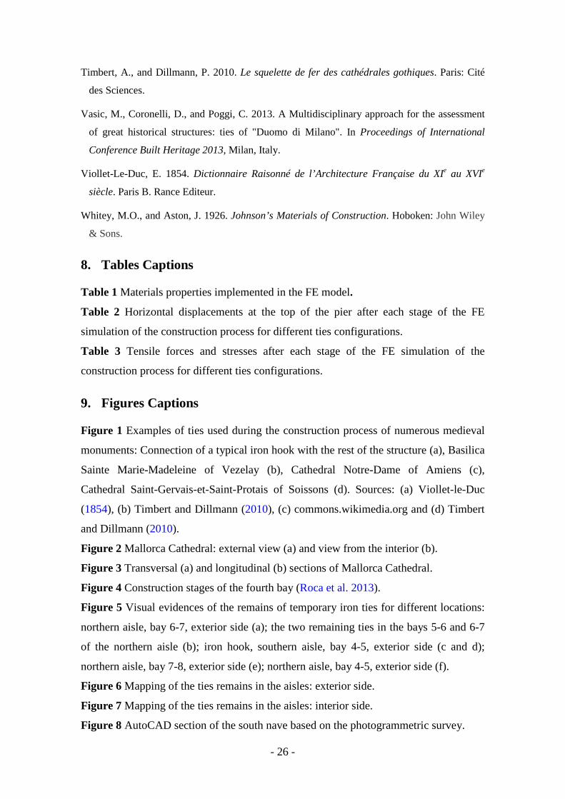
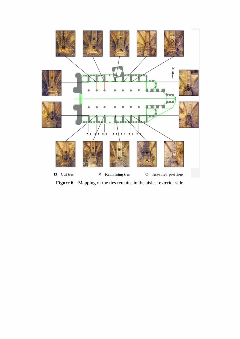
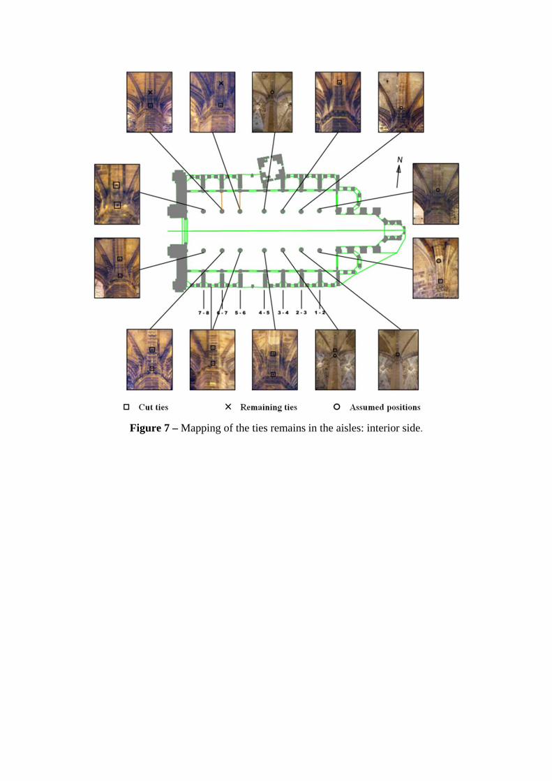
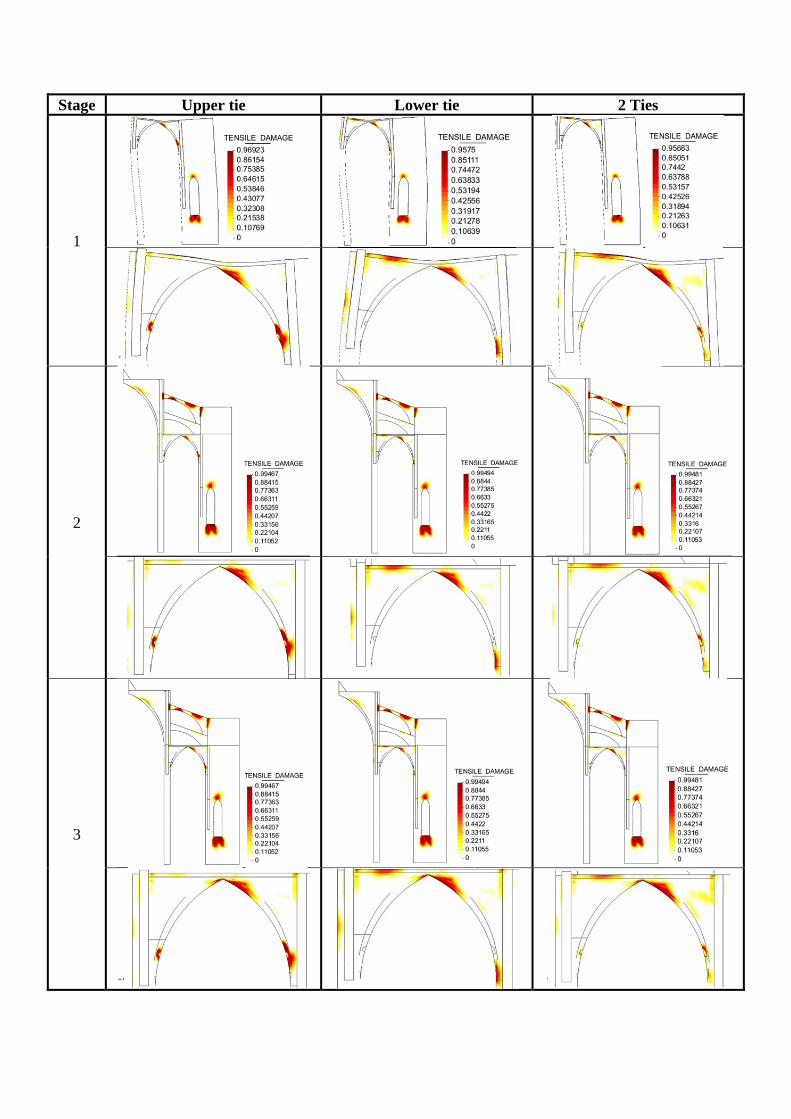
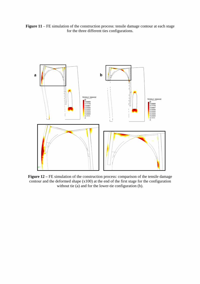
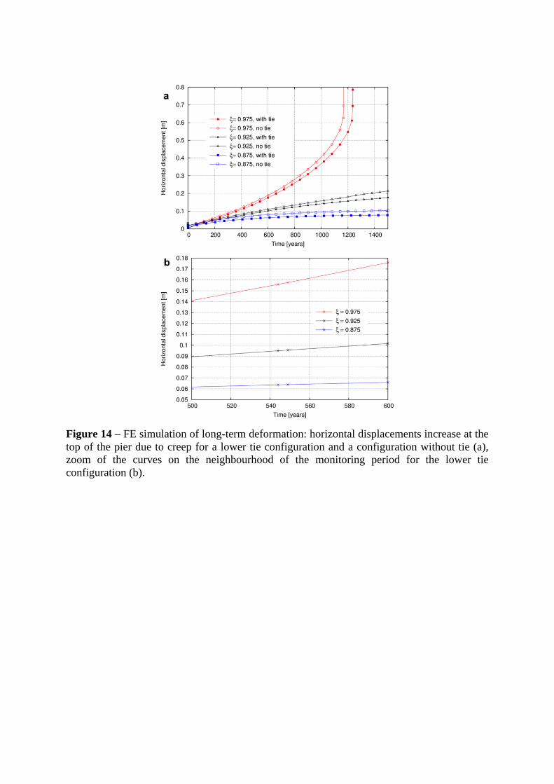