analysis of the magnetic coupling influence between ... · analysis of the magnetic coupling...
TRANSCRIPT

Analysis of the magnetic coupling influence
between different feeders on unbalanced
distribution networks
Code: 12.004
Nélio Alves do Amaral Filho, Mariana Simões Noel da Silva,
Leandro Ramos de Araujo, Débora Rosana Ribeiro Penido
Araujo
Electrical Engineering, Federal University of Juiz de Fora,
Minas Gerais - Brazil
12/11/2017 1
• Electrical distribution systems (DS) have attracted the attention of a
growing number of researchers
✓ Electric power quality
▪ Unbalances
✓ Increased demand for electricity
▪ Operation under harsher conditions
✓ Greater need to represent all DS-related characteristics and effects
✓ An efficient representation of the system components
✓ Tools able to evaluate and analyze the DS more accurately
Introduction
12/11/2017 2
• Several possible analyses can be performed in distribution systems
studies
✓ Electromagnetic coupling (mutual coupling) that occurs between
two or more feeders when physically arranged in parallel
✓ Practice done by the utilities
✓ Feeders can be found traveling along▪ the same path and sharing a common pole;
▪ the same power corridor on separate poles.
✓ The existing mutual coupling can significantly affect the system
✓ This coupling is usually neglected in most studies
Introduction
12/11/2017 3
• Analysis of the electromagnetic coupling influence between different
feeders
• Backward/Forward Sweep (BFS) Method
• Different constructive characteristics
✓ Length of the distribution feeders sections
✓ Separation distance between the conductors
✓ Phase sequences and geometry of the conductors on the poles
Objectives
12/11/2017 4

Model of the distribution feeders in parallel
12/11/2017 5
(1)1
0,07537 ln 6,74580ii c d
i
Z r r jRMG
(2)1
0,07537 ln 6,74580ij d
ij
Z r jD
' ' '
' ' '
' ' '
' ' ' ' ' ' ' ' '
aa ab ac aa ab ac
ba bb bc ba bb bc
ca cb cc ca cb cc
phase
a a a b a c a a a b a c
Z Z Z Z Z Z
Z Z Z Z Z Z
Z Z Z Z Z ZZ
Z Z Z Z Z Z
' ' ' ' ' ' ' ' '
' ' ' ' ' ' ' ' '
(3)
b a b b b c b a b b b c
c a c b c c c a c b c c
Z Z Z Z Z Z
Z Z Z Z Z Z
, 1 1 , 1 2
, 2 1 , 2 2
(4)
abc F F abc F F
phase
abc F F abc F F
Z ZZ
Z Z
A B C
B C A
n
Mutual: same feeder
Mu
tual
: di
ffe
ren
t fe
ede
r
FEEDER 1
FEEDER 20,76m
1,37m
0,6m
0,6m
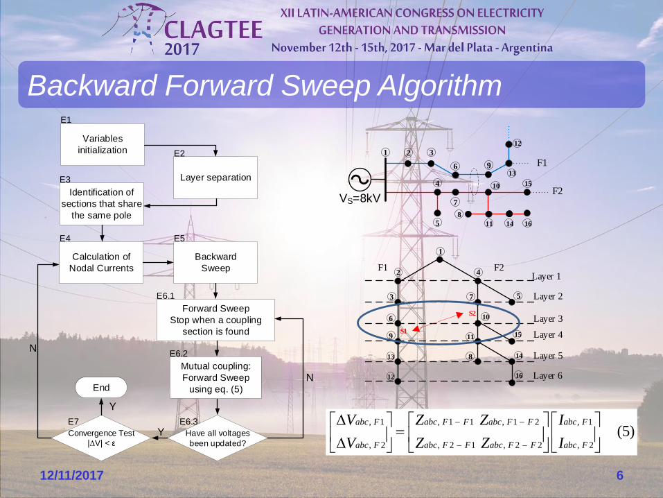
Backward Forward Sweep Algorithm
12/11/2017 6
1
VS=8kV
3
4
6
5
9
7
12
15
11 14
8
F1
F2
2
10
13
16
2 4
1
3 7 5
6
9
813
12
10
11 15
14
16
Layer 1
Layer 2
Layer 3
Layer 4
Layer 5
Layer 6
S1
S2
F1 F2
, 1 , 1 1 , 1 2 , 1
, 2 , 2 1 , 2 2 , 2
(5)
abc F abc F F abc F F abc F
abc F abc F F abc F F abc F
V Z Z I
V Z Z I
Layer separation
Calculation of
Nodal Currents
Backward
Sweep
E1
Variables
initialization
Forward Sweep
Stop when a coupling
section is found
Mutual coupling:
Forward Sweep
using eq. (5)
Convergence Test
|ΔV| < ε
Y
N
Have all voltages
been updated?
Y
N
E2
E3
E4
E6.1
E6.2
E6.3E7
Identification of
sections that share
the same pole
E5
End

.
12/11/2017 7
Simulated systems
650
651
VS=4,16 kV
632
671
675
6320
67506710
800
VS=24,9 kV
802 806
808
810
812 814 850
890
IEEE 13M IEEE 34M

• To investigate the impact of the mutual coupling, 2 cases were
analyzed✓ Case 1: ignoring the effect of the mutual impedances between different
feeders (without the mutual coupling representation)
✓ Case 2: considering the effect of these mutual impedances (mutual
coupling)
• For comparison and results presentation✓ It was calculated the difference between the absolute values obtained from
each case, for a same variable (voltage, current or electrical losses)
12/11/2017 8
Simulated systems
2 1
1
(6)k k
k
C C
kC
V VV
V

Feeders length
Experimental results
12/11/2017 9
IEEE 13M
0
2
4
6
8
10
12
14
16
18
20
0,1 0,5 1 1,5 2
Phase A
Phase B
Phase C
Factor k
Max
imum
vol
tage
dif
fere
nce
(%
)
0
2
4
6
8
10
12
14
16
18
20
0,1 0,5 1 1,5 2 2,5 3 3,5
Factor k
Max
imum
vol
tage
dif
fere
nce
(%
) Phase A
Phase B
Phase C
IEEE 34M

Distance between conductors
Experimental results
12/11/2017 10
0
0,01
0,02
0,03
0,04
0,05
0,06
0,07
0,08
0,15 0,3 0,5 0,75 1 1,25 1,5 1,75 2
Phase A
Phase B
Phase C
Distance between the center conductor and the left conductor (m)
Vo
ltag
e d
iffer
ence
in b
us 6
75 (
pu)
IEEE 13MIEEE 34M
0
0,5
1
1,5
2
2,5
0,2 0,3 0,6 1 2 4 10 50
Vertical distance between feeders on pole (m)
Vo
ltag
e d
iffer
ence
in b
us 8
90 (
%) Phase A
Phase B
Phase C
B A C
A B C
n
FEEDER 1
FEEDER 2
Dx
Dy
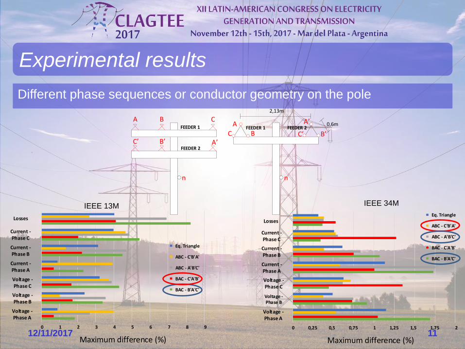
Different phase sequences or conductor geometry on the pole
Experimental results
12/11/2017 110 1 2 3 4 5 6 7 8 9
Voltage - Phase A
Voltage - Phase B
Voltage - Phase C
Current - Phase A
Current - Phase B
Current - Phase C
Losses
Eq. Triangle
ABC - C'B'A'
ABC - A'B'C'
BAC - C'A'B'
BAC - B'A'C'
Maximum difference (%)
0 0,25 0,5 0,75 1 1,25 1,5 1,75 2
Voltage - Phase A
Voltage - Phase B
Voltage - Phase C
Current - Phase A
Current - Phase B
Current - Phase C
LossesEq. Triangle
ABC - C'B'A'
ABC - A'B'C'
BAC - C'A'B'
BAC - B'A'C'
Maximum difference (%)
IEEE 34MIEEE 13M
A B C
B C A
n
FEEDER 1
FEEDER 2
C B C
A
n
FEEDER 1 FEEDER 2A
B
0,6m
2,13m

• The effect of the mutual coupling may become significant in certain
conditions
✓ System configuration;
✓ Long length of feeders sections that are in parallel;
✓ Small distances between the phase conductors, both vertically and
horizontally;
✓ Specific phase sequences.
• The mutual coupling influence can be considerable not only in the
voltage, but also in both current and electrical losses
• The mutual coupling representation in the power flow analysis
algorithms for distribution systems should not be neglected
Conclusions
12/11/2017 12

The authors thank the Pos-Graduate Program in Electrical Engineering
(PPEE) of the Federal University of Juiz de Fora, CNPq, FAPEMIG, and
CAPES for the incentive and support.
Acknowledgments
12/11/2017 13

[1] W. H. Kersting, “The modeling and analysis of parallel distribution lines,” in Rural Electric Power Conference,
2005, 2005, p. A3/1-A3/7.
[2] L. R. de Araujo, “Representation of Magnetic Coupling in Distribution System Feeders Using BW/FW,” IEEE
Trans. Power Syst., vol. 32, no. 2, pp. 1580–1581, Mar. 2017.
[3] R. Yan and T. K. Saha, “Analysis of unbalanced distribution lines with mutual coupling across different voltage
levels and the corresponding impact on network voltage,” Transm. Distrib. IET Gener., vol. 9, no. 13, pp. 1727–1737, 2015.
[4] L. M. Popovic, “A practical method for evaluation of ground fault current distribution on double circuit parallel
lines,” IEEE Trans. Power Deliv., vol. 15, no. 1, pp. 108–113, Jan. 2000.
[5] S. A. Wheeler, “Influence of mutual coupling between parallel circuits on the setting of distance protection,”
Proc. Inst. Electr. Eng., vol. 117, no. 2, pp. 439–445, Feb. 1970.
[6] D. A. Tziouvaras, H. J. Altuve, and F. Calero, “Protecting mutually coupled transmission lines: Challenges and
solutions,” in 2014 67th Annual Conference for Protective Relay Engineers, 2014, pp. 30–49.
[7] C. Pritchard, T. Hensler, J. Coronel, and D. Gachuz, “Test and analysis of protection behavior on parallel lines
with mutual coupling,” in 2016 IEEE PES Transmission Distribution Conference and Exposition-Latin America (PES T D-LA),
2016, pp. 1–5.
[8] W. H. Kersting, Distribution System Modeling and Analysis, Second Edition, 2 edition. CRC Press, 2006.
[9] C. S. Cheng and D. Shirmohammadi, “A three-phase power flow method for real-time distribution system
analysis,” IEEE Trans. Power Syst., vol. 10, no. 2, pp. 671–679, May 1995.
[10] M. H. Haque, “A general load flow method for distribution systems,” Electr. Power Syst. Res., vol. 54, no. 1, pp.
47–54, Apr. 2000.
[11] U. Eminoglu and M. H. Hocaoglu, “Distribution Systems Forward/Backward Sweep-based Power Flow
Algorithms: A Review and Comparison Study,” Electr. Power Compon. Syst., vol. 37, no. 1, pp. 91–110, Dec. 2008.
[12] “Distribution Test Feeders - Distribution Test Feeder Working Group - IEEE PES Distribution System Analysis
Subcommittee.” [Online]. Available: https://ewh.ieee.org/soc/pes/dsacom/testfeeders/. [Accessed: 23-May-2017].
References
12/11/2017 14