analysis of thermal evolution in textile fabrics using
TRANSCRIPT

ANALYSIS OF THERMAL EVOLUTION IN TEXTILEFABRICS USING ADVANCED MICROSTRUCTURE
SIMULATION TECHNIQUES
MATTHIAS ROMMELT∗, ANASTASIA AUGUST2, BRITTA NESTLER2
AND ARON KNEER1
∗,1 TinniT Technologies GmbHErbprinzenstr. 32, 76133 Karlsruhe, Germany
Email: [email protected] - Web page: http://www.tinnit.de/
2 Karlsruhe Institute of TechnologyInstitute for Applied Matererials
Haid-und-Neu-Str. 7, 76131 Karlsruhe, GermanyEmail: [email protected] - Web page: http://www.iam.kit.edu/zbs
Key words: CFD, Environmental Technologies, Numerical Methods, Textile Compos-ites, Thermal Evolution
Abstract. Nowadays, membrane structures represent a modern construction elementto be used as roof material in modern buildings or as design element in combinationwith traditional architecture. Membranes are mostly used in an outdoor environment.Therefore they are exposed to wind, radiation (solar and infrared), rain and snow. Specificmembranes are three-dimensional fabrics which can be used as energy absorber or asinsulation of membrane roofs. The applicability as energy absorber becomes important ifthe three-dimensional fabrics are designed as a porous flow channel streamed by air andconvectively heated up. The transferred energy may be stored in a latent heat storagesystem.
Due to their porous structure, textile fabrics have a large heat-exchanging surface. Ifthey are handled as homogenized porous structures, the heat transfer processes can notbe described in a correct way. Therefore a microstructure model locally resolving allfilaments of the three-dimensional fabrics has been formulated. By using an advancedmeshing tool, a simulation technique has been developed taking into account the localheat conduction properties of the different materials.
To analyse the heat transfer processes inside the three-dimensional fabrics, numericalsimulations have been performed using the phase-field solver (Pace3D) of the KarlsruheInstitute of Technology and the commercial CFD-Solver StarCCM+. For a better under-standing of the thermal behaviour of the fabrics, different thermal loads including thermalconduction in the microstructure (filaments) and convection by the surrounding air have
1
International Conference on Textile Composites and Inflatable StructuresSTRUCTURAL MEMBRANES 2011
E. Oñate, B. Kröplin and K.-U.Bletzinger (Eds)

Matthias Rommelt, Anastasia August, Britta Nestler and Aron Kneer
been computed. The results show that the advanced simulation techniques allow to anal-yse the rate of conductive and convective heat transfer in three-dimensional fabrics. Theresults of the applied computational methods are compared.
1 INTRODUCTION
As a part of the polar bear project, a textile pilot building is constructed. The textilestructure is used to generate heat and copy the fur of the polar bear [3]. The use of textilestructures as a thermal collector offers many advantages. Textile structures are flexibleand can be used as a self-supporting roof or on rooftops. Here, in addition to generatingheat, the insulation is important. In the future textile structures will be used on roofswith an area ranging from several up to 10000 m2.
roof
solarradiation
heatinsulationheatinsulation
heat radiationreflection
airflow
membranestructure
Figure 1: Design and principle of a thermal collector with membrane structures.
The operating principle is shown in Figure 1. To have a well insulating textile fabricthat can be used as a thermal heat collector, it must have the following characteristics:
1. Solar radiation should be transmitted.
2. Heat radiation from the roof and the heated structure should be reflected.
3. The textile fabric should have a low thermal conductivity.
4. Flowing through air should absorb heat from the textile fabric.
The solution is a construction of three different textile structures. Figure 2 shows thestructure. Layer 2 and 3 transmit solar radiation and reflect heat radiation. Layer 1
2

Matthias Rommelt, Anastasia August, Britta Nestler and Aron Kneer
12
mm
20
mm
10
mm
layer 1
layer 3
layer 2
Figure 2: Thermal collector composed of 3 layers of textile spacer fabrics.
absorbs solar radiation and air flows through. All three layers act as insulation. In thefollowing property 3 and 4 are considered in more detail.
To calculate the physical processes in the textile, a detailled model resolving the struc-ture is needed. The complete structure is required for the calculation of heat conduction,the surface for convective heat transfer. The textile membranes are used industrially on alarge scale. It is not possible to calculate large areas of textile structures with resolutionof the finest fibers with today’s computing capacity. Therefore, it is necessary to repro-duce small units of the textile structure with all the fibres in a representative volume.Using these models the physical processes are calculated and we obtain, for example, atemperature profile or a pressure profile within the structure. Thus it is possible to bet-ter understand the processes in the textile structure and to calculate effective materialparameters and dimensional parameters for the modeled structure unit. Effective mate-rial parameters and dimensionless parameters allow a calculation of large areas, becauseinstead of an exact resolution of the structure, effective material parameters are used.
The following sections explain the pre-processing, calculation, evaluation and determi-nation of effective material parameters for the textile structure in Figure 2.
2 PREPROCESSING
The model generation is described for layer 1 in Figure 3. In a first step, the struc-ture is analysed. The structure consists of three different textile fiber elements, whichrecur periodically within the tissue. The geometric dimensions of the structure and theindividual structural elements are required for the reconstruction.
In a second step the individual structural elements are replicated. Therefore the pro-gram Pace3D was used. Pace3D stands for Parallel Algorithm in Crystal evolution in3D. The software package was developed for materials science applications in order to
3
Matthias Rommelt, Anastasia August, Britta Nestler and Aron Kneer
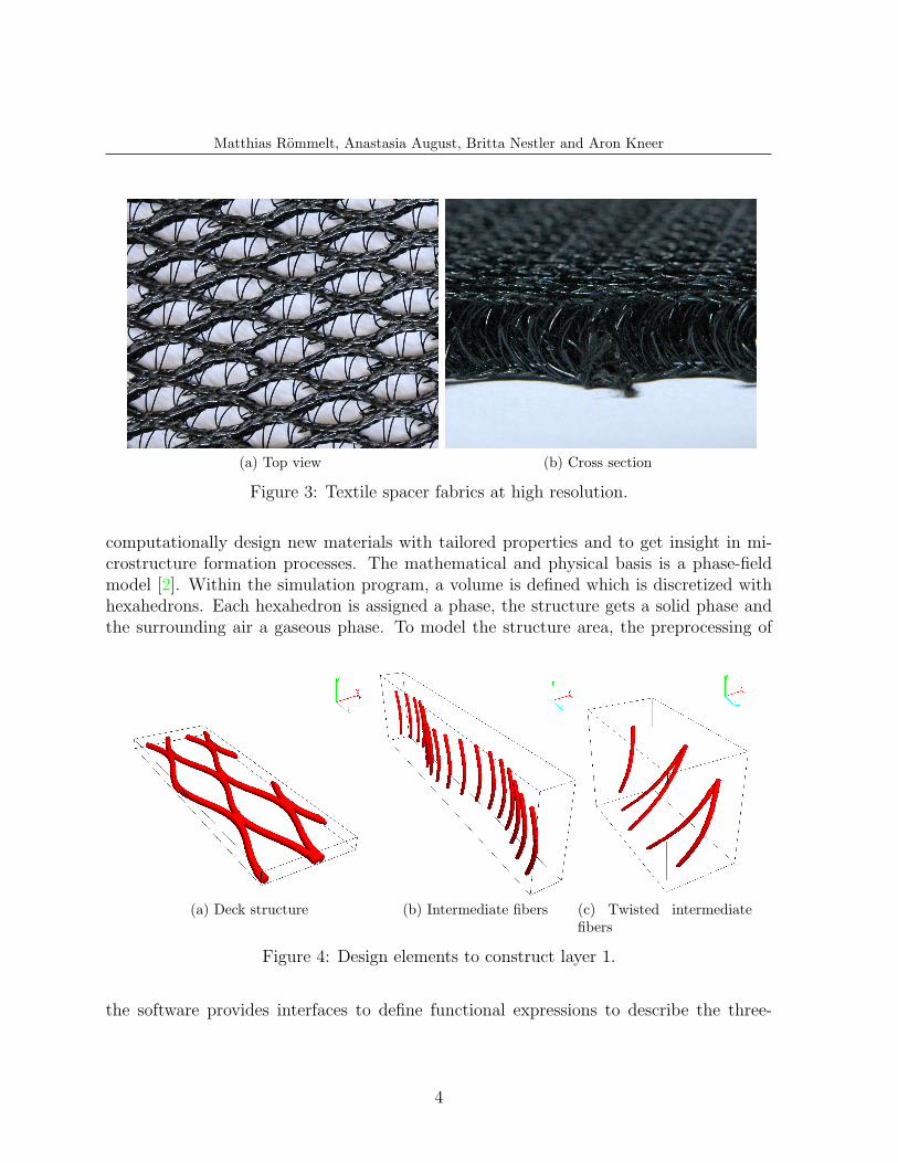
(a) Top view (b) Cross section
Figure 3: Textile spacer fabrics at high resolution.
computationally design new materials with tailored properties and to get insight in mi-crostructure formation processes. The mathematical and physical basis is a phase-fieldmodel [2]. Within the simulation program, a volume is defined which is discretized withhexahedrons. Each hexahedron is assigned a phase, the structure gets a solid phase andthe surrounding air a gaseous phase. To model the structure area, the preprocessing of
(a) Deck structure (b) Intermediate fibers (c) Twisted intermediatefibers
Figure 4: Design elements to construct layer 1.
the software provides interfaces to define functional expressions to describe the three-
4

Matthias Rommelt, Anastasia August, Britta Nestler and Aron Kneer
dimensional geometry. In the case of the deck fibre, it is a sine function
F1(z) = amp · sin(z · 2π
λ
). (1)
The parameters were taken from the geometric dimensions. The fiber was then multipliedto get the deck structure.
When creating the second structure type, the intermediate fibers, the procedure wascomparable. They were also modeled with a sine function. The duplication of the fiberis based on the sine function in equation (1). The twisted intermediate fibers form thethird type of fiber. They have the special feature keeping overlying deck fibres seperateand connecting diagonally above the other deck fiber. Therefore, two functions overlap,a linear shift in x-direction and a sine-function in z-direction. Figure 4 shows the threestructural elements.
In a third step, the structural elements are combined and superimposed. The result isthe overall structure in Figure 5a. Layer 2 and 3 were created similarly. They are shown
(a) Layer 1 (b) Layer 3 (c) Layer 2
Figure 5: Modeled layers of the thermal collector.
in Figure 5b and 5c.By formulating suitable mathematical expressions, a twisted deck fiber in Figure 6 can
be generated. It is composed of four single fibers twisted together and shaped in the formof a sine curve. In the further refinement of the structure it has to be estimated, whetherthis improves the accuracy of the calculation or just increases the computational cost andcomplexity.
3 CALCULATED LOADCASES
Based on the structural model in Figure 5a different calculations were performed. Inaddition to Pace3D, StarCCM+ was used for calculation. StarCCM+ is a commercialComputational Fluid Dynamics (CFD) code. There were three aims:
• Analysis of physical processes in the structures
5

Matthias Rommelt, Anastasia August, Britta Nestler and Aron Kneer
Figure 6: Twisted deck structure fiber.
• Comparing the results of Pace3D and StarCCM+
• Calculation of effective material parameters
For this purpose two load cases LC1 and LC2 were defined. The textile fabric is made ofpolyamide surrounded by air. The used material parameters are given in Table 1 and aretaken from the VDI-Warmeatlas [1].
Material Polyamide Air
T = 323.15 K T = 333.15 K
Density ρ [ kgm3 ] 1150.0(T=293.15 K) 1.046
Heat capacity cp [ Jkg·K ] 1680.0 1008.2
Heat conductivity λ [ Wm·K ] 330.0 · 10−3 28.8 · 10−3
Dynamic viscosity ν [m2
s] - 192.2 · 10−7
Table 1: Material values for LC1 und LC2.
3.1 Load case LC1
We calculated the steady-state heat conduction through the textile structure. For thecalculation, the smallest periodic unit (unit cell) of the textile structure was consideredand model-appropriate temperature conditions imposed. Figure 7a shows the selectedboundary conditions. For the calculation with Pace3D, also a base plate was added(Figure 7c). The base plate is made of polyamide and has the height ∆y = 1 mm. Usingthis base plate it is possible to calculate the heat flow through the structure. For thecalculation with StarCCM+ the construction of a base plate is not necessary (Figure 7b).
Due to the non-stationary solution scheme of Pace3D, the simulation has to run for along physical time until a steady-state temperature profile has formed over the structure.
6

Matthias Rommelt, Anastasia August, Britta Nestler and Aron Kneer
y
Txz,y=h =293.15K
Txz,y=0 =373.15K
Tt=0,stucture =333.15Kxz
(a) Boundary and initial condi-tions
(b) StarCCM+ without plate (c) Pace3D with plate
Figure 7: Boundary conditions and simulation environment (LC1).
This is reached after about 100 s. In addition, the initial conditions were chosen so,that they are close to a steady-state temperature profile. For the textile structure, wechose Tt=0,structure = 333.15 K and for the base plate Tt=0,plate = 373.15 K. StarCCM+calculates at steady-state conditions and implicitly, therefore the required computing timeis lower.
3.2 Load case LC2
For load case LC 2, four unit cells like in Figure 7b were joined together. This structuralunit is flown through by air in a channel and heated from below with a temperatureTyz,x=0 = 373.15 K. The structure and air are heated. The convective and conductiveheat transfer and pressure loss are considered. Figure 8 shows the geometry and boundaryconditions. The channel has a length of Lchannel = 210 mm. The structure is passedthrough in the direction of the x-axis with a speed of u = 1.0 m
s. The temperature of the
fluid at the inlet is Tinlet = 293.15 K. To estimate the Reynolds number, a channel cross-section between two intermediate fibers of d = 1.75 mm and an increased flow velocity ofumax = 2.0 m
sis assumed. It results in a Reynolds number of
Re =umax · d
ν= 182.1 . (2)
The flow has established steady-state and remains at laminar conditions.
4 RESULTS
The LC1 for the layer 1 was calculated with Pace3D and StarCCM+. The resultsillustrate the temperature layers in Figure 9a for stationary state. Figure 9b shows the
7

Matthias Rommelt, Anastasia August, Britta Nestler and Aron Kneer
Figure 8: Geometry and boundary conditions (LC2).
(a) Steady temperature distribution
0
2
4
6
8
10
12
290 300 310 320 330 340 350 360 370 380
Hei
ght y
[mm
]
Temperature [K]
ab
cStarCCM+
Pace3D
(b) TA over height y
Figure 9: Temperature distribution and profile.
temperature distribution over the height of the structure. The diagram was obtained byaveraging the temperature over the xz-plane.
The heat flow through the structure is calculated with StarCCM+ as Q = 60.2·10−3 W .For Pace3D, the heat flow can be calculated using the temperature difference over thebase plate. The temperature difference is ∆T = 0.9 K. With the corresponding geometricvalues, we get Q = 56.2 · 10−3 W using
Q =λ
∆y·∆T · A . (3)
LC2 was calculated for layer 1 with StarCCM+. Figure 10 shows the stationary tem-perature profile for the xy-plane. By the hot plate, heat is applied to the structure and the
8

Matthias Rommelt, Anastasia August, Britta Nestler and Aron Kneer
Variable StarCCM+ Pace3D
Area A = ∆x ·∆z [m2] 185.2 · 10−6 189.3 · 10−6
Height ∆ystructure [m] 9.9 · 10−3 10.2 · 10−3
Temperature difference ∆Tstructure [K] 80 79.4
Heat flow Q [W ] 60.2 · 10−3 56.2 · 10−3
Table 2: Geometric values and results of LC1.
Figure 10: Temperature distribution in the xy-layer (LC2).
air. The air is heated from Tinlet = 293.15 K to Toutlet = 300.29 K. The supplied heat en-ergy is Q = 1.762 W . The averaged temperature of the structure is Tstructure = 319.49 Kand of the air between the structure Tfluid = 302.43 K.
(a) pressure distribution (b) velocity vectors
Figure 11: Pressure distribution and velocity vectors for the xz-layer (LC2).
During flow through the structure, a stagnation point is formed in front of the fibers.Between the fibers, the flow is accelerated due to the cross-section. Figure 11a depicts
9

Matthias Rommelt, Anastasia August, Britta Nestler and Aron Kneer
the pressure distribution over the structure. The pressure loss during flow through thestructure is ∆p = 3.7 Pa. Figure 11b displays the velocity vectors in the xz-plane for apart of the structure. The velocity vectors reveal the flow around the individual fibers. Toreflect these phenomena within the structure, it is necessary to accurately reproduce thestructure. The maximum speed discovered in the computational domain is umax = 2.28 m
s.
With this value, our estimation used to calculate the Reynolds number turns out to becorrect.
5 DISCUSSION
The results of the temperature versus height y in Figure 9b and obtained by StarCCM+and Pace3D are almost identical. Position a) in the diagram shows the temperature curveabove the base plate. Position b) and c) correspond to the lower and upper deck structure.Here the proportion of polyamide is higher than in the area of the intermediate fibers.The thermal conductivity is greater in these areas, because they have a lower temperaturegradient. The proportion of polyamide and the course of the fibers have an influence onthe thermal conductivity. For technical applications, the effective thermal conductivityof the entire structure is important. This is given by
λeff =Q ·∆ystructure
∆Tstructure · A. (4)
With the values from Table 2 for the layer 1, the effective thermal conductivities of thetwo simulation applications are λeff,StarCCM+ = 40.2 · 10−3 W
K·m and λeff,Pace3D = 38.1 ·10−3 W
K·m . The deviation of the calculated values is 5.2% with respect to λeff,StarCCM+.This small difference and the similar temperature distribution in Figure 9b serve as avalidation of the results. LC1 was also used for the layers 2 and 3 with StarCCM+, and
Layer λeff [ Wm·K ] cp [ J
kg·K ] ρ [ kgm3 ]
Layer 1 40.2 · 10−3 1048.5 70.0
Layer 2 33.4 · 10−3 1026.5 32.4
Layer 3 32.8 · 10−3 1018.7 19.1
Complete structure 34.4 · 10−3 1027.8 34.6
Table 3: Calculated values for the three layers with StarCCM+ (LC1).
the effective thermal conductivity was calculated. Table 3 contains the resulting values.With the effective thermal conductivity of the three layers, it is possible to determine aneffective thermal conductivity for the whole structure of λeff,tot = 34.4 · 10−3 W
m·K , whichis 19.4% larger than the thermal conductivity of pure air. The whole structure has goodthermal insulating properties similar to air. This value can be used for technical design
10

Matthias Rommelt, Anastasia August, Britta Nestler and Aron Kneer
of large textile surfaces. In conclusion, the thermal insulation properties can be correctlyreproduced without resolution of the exact structures.
Another important feature to evaluate and interpret is the heat transfer from thestructure to the fluid. The heat transfer coefficient α specifies the transferred heat powerper surface and temperature difference. For textile membranes, there is no valid Nusseltnumber correlation. With the values of the LC2, the heat transfer coefficient for layer 1can be estimated to
α =Q
Astructure · (Tstructure − Tfluid), (5)
where Astructure = 2.26 · 10−3 m2 is the interface area between fluid and structure. Thisresults in an averaged value of α = 139.1 W
m2·K . For comparison, the heat transfer coeffi-cient for an overflown, heated plate was calculated to α = 22.0 W
m2·K by the correspondigNusselt number correlation of the VDI-Warmeatlas [1]. The heat transfer in the flow isincreased by the structure. The heat is taken away from the structure by the air flowingthrough, and can be stored for example in a latent heat storage.
Figure 12: Temperature distribution in the textile fiber.
As seen in Figure 10, the heat only penetrates into the flow region at the bottom ofthe channel. Figure 12 emphasizes this, the fiber is heated only in the lower third. Thecorresponding Biot number is the heat transfer between fluid and structure in relation toheat conduction in the structure. It can be estimated with α as
Bi =α · Lstructure
λstructure
. (6)
The characteristic length of the structure Lstructure is given by the structure height ∆y =9.85 · 10−3 m and λstructure = 330.0 · 10−3 W
m·K refers to λPolyamide. This results in the
11
Matthias Rommelt, Anastasia August, Britta Nestler and Aron Kneer
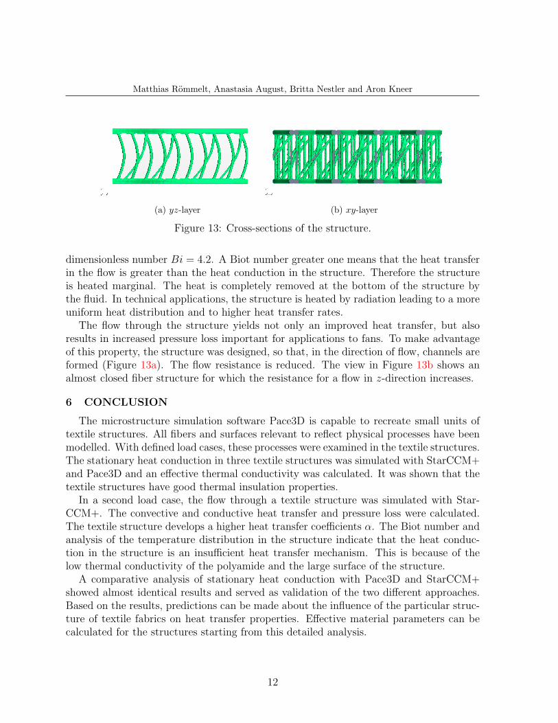
(a) yz-layer (b) xy-layer
Figure 13: Cross-sections of the structure.
dimensionless number Bi = 4.2. A Biot number greater one means that the heat transferin the flow is greater than the heat conduction in the structure. Therefore the structureis heated marginal. The heat is completely removed at the bottom of the structure bythe fluid. In technical applications, the structure is heated by radiation leading to a moreuniform heat distribution and to higher heat transfer rates.
The flow through the structure yields not only an improved heat transfer, but alsoresults in increased pressure loss important for applications to fans. To make advantageof this property, the structure was designed, so that, in the direction of flow, channels areformed (Figure 13a). The flow resistance is reduced. The view in Figure 13b shows analmost closed fiber structure for which the resistance for a flow in z-direction increases.
6 CONCLUSION
The microstructure simulation software Pace3D is capable to recreate small units oftextile structures. All fibers and surfaces relevant to reflect physical processes have beenmodelled. With defined load cases, these processes were examined in the textile structures.The stationary heat conduction in three textile structures was simulated with StarCCM+and Pace3D and an effective thermal conductivity was calculated. It was shown that thetextile structures have good thermal insulation properties.
In a second load case, the flow through a textile structure was simulated with Star-CCM+. The convective and conductive heat transfer and pressure loss were calculated.The textile structure develops a higher heat transfer coefficients α. The Biot number andanalysis of the temperature distribution in the structure indicate that the heat conduc-tion in the structure is an insufficient heat transfer mechanism. This is because of thelow thermal conductivity of the polyamide and the large surface of the structure.
A comparative analysis of stationary heat conduction with Pace3D and StarCCM+showed almost identical results and served as validation of the two different approaches.Based on the results, predictions can be made about the influence of the particular struc-ture of textile fabrics on heat transfer properties. Effective material parameters can becalculated for the structures starting from this detailed analysis.
12

Matthias Rommelt, Anastasia August, Britta Nestler and Aron Kneer
For the complete design of thermal collectors, made of textile membranes, a forthcomingresearch will adress the following issues:
• the definition of additional load cases
– to study the radiation behaviour of textile structures.
– to create a pressure correlation for calculating the pressure drop at differentoperating points and flow lengths.
• validation by experimental data.
• structural optimization considering the required heat and flow characteristics.
REFERENCES
[1] VDI-Warmeatlas. VDI Buch. Springer, Berlin, 10. edition, 2006. 3, 5
[2] B. Nestler, H. Garcke, and B. Stinner. Multicomponent alloy solidification phasefieldmodelling and simulations. Physical Review, 71, 2005. 2
[3] T Stegmaier, M. Linke, and H Planck. Bionics in textiles: flexible and translucentthermal insulations for solar thermal applications. Phil. Trans. R. Soc., (367):1749–1758, 2009. 1
13