analysis of underground storage tank system materials to ... · pdf fileornl/tm-2011/xxx...
TRANSCRIPT

ORNL/TM-2012/182
Analysis of Underground Storage Tank System Materials to Increased Leak Potential Associated with E15 Fuel
July 2012
Prepared by
M. D. Kass T. J. Theiss C. J. Janke S. J. Pawel

DOCUMENT AVAILABILITY
Reports produced after January 1, 1996, are generally available free via the U.S. Department of Energy (DOE) Information Bridge. Web site http://www.osti.gov/bridge Reports produced before January 1, 1996, may be purchased by members of the public from the following source. National Technical Information Service 5285 Port Royal Road Springfield, VA 22161 Telephone 703-605-6000 (1-800-553-6847) TDD 703-487-4639 Fax 703-605-6900 E-mail [email protected] Web site http://www.ntis.gov/support/ordernowabout.htm Reports are available to DOE employees, DOE contractors, Energy Technology Data Exchange (ETDE) representatives, and International Nuclear Information System (INIS) representatives from the following source. Office of Scientific and Technical Information P.O. Box 62 Oak Ridge, TN 37831 Telephone 865-576-8401 Fax 865-576-5728 E-mail [email protected] Web site http://www.osti.gov/contact.html
This report was prepared as an account of work sponsored by an agency of the United States Government. Neither the United States Government nor any agency thereof, nor any of their employees, makes any warranty, express or implied, or assumes any legal liability or responsibility for the accuracy, completeness, or usefulness of any information, apparatus, product, or process disclosed, or represents that its use would not infringe privately owned rights. Reference herein to any specific commercial product, process, or service by trade name, trademark, manufacturer, or otherwise, does not necessarily constitute or imply its endorsement, recommendation, or favoring by the United States Government or any agency thereof. The views and opinions of authors expressed herein do not necessarily state or reflect those of the United States Government or any agency thereof.
ORNL/TM-2011/XXX
ANALYSIS OF UNDERGROUND STORAGE TANK
SYSTEM MATERIALS TO INCREASED LEAK
POTENTIAL ASSOCIATED WITH E15 FUEL
Michael D. Kass, Timothy J. Theiss, Christopher J. Janke, and Steve Pawel
Date Published: July 2012
Prepared by
OAK RIDGE NATIONAL LABORATORY
Oak Ridge, Tennessee 37831-6283
managed by
UT-BATTELLE, LLC
for the
U.S. DEPARTMENT OF ENERGY
under contract DE-AC05-00OR22725


iii
CONTENTS
Page
LIST OF FIGURES ...................................................................................................................................... v LIST OF TABLES ...................................................................................................................................... vii ACRONYMS ............................................................................................................................................... ix FOREWARD ............................................................................................................................................... xi ACKNOWLEDGMENTS ......................................................................................................................... xiii EXECUTIVE SUMMARY ........................................................................................................................ xv 1. INTRODUCTION ................................................................................................................................ 1
1.1 HISTORY AND BACKGROUND ............................................................................................ 1 1.2 ETHANOL COMPATIBILITY AND SOLUBILITY ................................................................ 2 1.3 FUELING DISPENSER MATERIALS AND ETHANOL COMPATIBILITY STUDY .......... 5
2. UNDERGROUND TANKS & PIPING SYSTEMS ............................................................................ 6 2.1 METALLIC MATERIALS FOR TANKS, COMPONENTS, AND PIPING SYSTEMS ......... 7 2.2 POLYMER PIPING AND TANK SYSTEMS ........................................................................... 8
2.2.1 Flexible Plastic Piping ................................................................................................... 8 2.2.2 Fiber-reinforced Plastic Tanks & Piping ..................................................................... 13
3. ELASTOMERS, SEALANTS, COUPLINGS AND FITTINGS ....................................................... 19 3.1 ELASTOMERS ........................................................................................................................ 19 3.2 PIPE THREAD SEALANTS .................................................................................................... 21 3.3 COUPLINGS AND FITTINGS ................................................................................................ 22
4. CONCLUSIONS ................................................................................................................................ 24 4.1 CONCLUSION ON TANKS AND PIPING MATERIALS .................................................... 24 4.2 CONCLUSION ON ELASTOMERS, SEALANTS, COUPLINGS AND FITTINGS ............ 25
5. REFERENCES ................................................................................................................................... 25


v
LIST OF FIGURES
Figure Page
1 Electrical conductivity of gasoline as a function of ethanol concentration. .............................. 3 2 Electrical conductivity of gasoline as a function of ethanol and water content. ....................... 4 3 Total Hansen Solubility Parameter as a function of ethanol concentration............................... 5 4 Cross-section diagram of flexible piping showing an example of the layering position
and arrangement of materials used in double-walled designs. .................................................. 9 5 Volume swell results for representative barrier materials used in underground piping. ......... 10 6 Absolute hardness results for representative barrier materials used in flexible piping. .......... 11 7 Point change in hardness (from baseline) for representative barrier materials used in
flexible piping.......................................................................................................................... 11 8 Diagram of fiber-reinforced plastic piping. ............................................................................. 14 9 Volume swell results for UST resins following exposure to Fuel C and CE25a. ................... 15 10 Mass change for UST resins following exposure to Fuel C and CE25a. ................................ 15 11 Point change in hardness for the UST resin samples following exposure to Fuel C and
CE25a. ..................................................................................................................................... 17 12 Photograph showing the Batch 1 specimens before and after exposure to Fuel C,
CE50a, and CE85a. ................................................................................................................. 18 13 Photograph showing the Batch 2 specimens before and after exposure to Fuel C,
CE50a, and CE85a. ................................................................................................................. 18 14 Photograph showing the Batch 3 specimens before and after exposure to Fuel C,
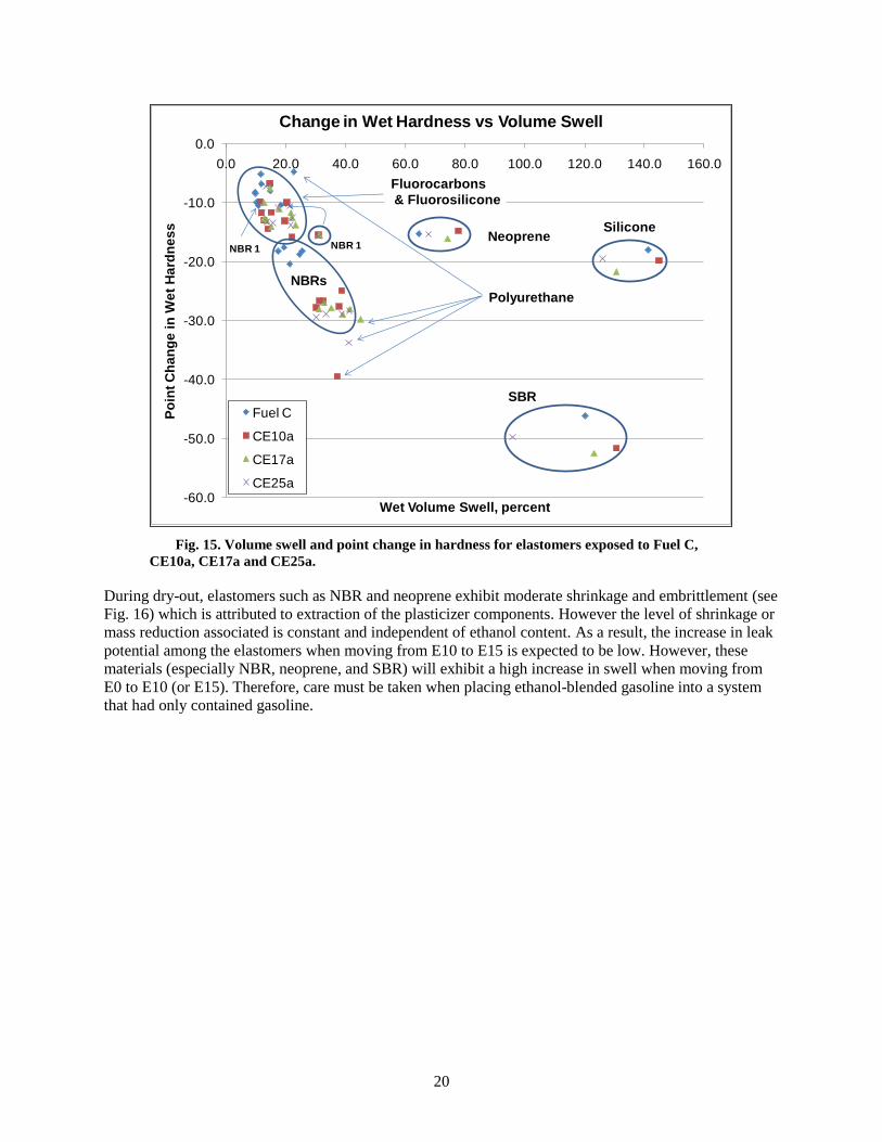
CE50a, and CE85a. ................................................................................................................. 19 15 Volume swell and point change in hardness for elastomers exposed to Fuel C, CE10a,
CE17a and CE25a. .................................................................................................................. 20 16 Percent mass change and point change in hardness for elastomers exposed to Fuel C,
CE10a, CE17a and CE25a following dry-out. ........................................................................ 21 17 Simplified schematic showing attachment of a coupling to flexible plastic piping. ............... 22 18 Schematic diagram of the butt and strap joint. ........................................................................ 23 19 Schematic showing a common arrangement of using adhesive on FRP piping. ..................... 23


vii
LIST OF TABLES
Tables Page
1 List of materials evaluated in intermediate ethanol blends compatibility study.
(Materials identified as being used in UST systems are highlighted.) ...................................... 6 2 Breakdown of piping materials.
5,19 ............................................................................................ 7
3 Flexible piping materials according to manufacturer. ............................................................... 8 4 Volume swell results for representative barrier materials used in flexible underground
piping ....................................................................................................................................... 13 5 Measured and calculated results for PVDF and Nylon 6 ........................................................ 13 6 Measured and calculated results for UST resins Vipel F774 and Vipel F085 ......................... 16


ix
ACRONYMS
ASTM American Society for Testing and Materials
DOE Department of Energy
E10 Gasoline containing 10% ethanol by volume
E15 Gasoline containing 15% ethanol by volume
E50 Gasoline containing 50% ethanol by volume
E85 Gasoline containing 85% ethanol by volume
EISA Energy Independence and Security Act
EPA U. S. Environmental Protection Agency
F-HDPE Fluorinated high density polyethylene
Fuel C A gasoline representative test fuel composed of 50%vol. toluene and 50%vol. isooctane
FRP Fiber-reinforced plastic
FFV Flex-Fuel Vehicle
HDPE High density polyethylene
HSP Hansen Solubility Parameter
ISO International Organization for Standardization
LG Leaded gasoline
MIC Microbial-induced corrosion
MTBE Methyl tertiary butyl ether
NBR Acrylonitrile (or nitrile) butadiene rubber
NREL National Renewable Energy LaboratoryOBP DOE Office of Biomass Program
ORNL Oak Ridge National Laboratory
PBT polybutylene terephthalate
PEI Petroleum Equipment Institute
PET polyethylene terephthalate
PP polypropylene
PTFE polytetrafluoroethylene
PCV polyvinyl chloride
PVDF polyvinylidene fluoride
RFS Renewable Fuel Standard
S Siemens (unit of electrical conductivity)
SAE Society of Automotive Engineers
SBR Styrene butadiene rubber
UL Underwriters Laboratories
UST Underground Storage Tank
VS Volume swell
VTP DOE Vehicle Technologies Program


xi
FOREWARD
It is not the purpose of this report to define the acceptable limits of material performance or to rate
individual materials. Rather, the purpose of this study was to assess critical property changes (volume,
hardness, mass, etc.) for representative classes of materials used in underground storage tank systems
with exposure to E15.


xiii
ACKNOWLEDGMENTS
This report and the work described were sponsored by the United States Environmental Protection
Agency Office of Underground Storage Tanks (EPA OUST). The authors gratefully acknowledge the
support and editorial guidance of Andrea Barbery, Linda Gerber, Mark Barolo, and Paul Miller from the
EPA OUST. This manuscript was greatly improved by the thorough reviews of Ed English of Fuel
Quality Services, and Ken Boyce and Tom Chapin of Underwriters Laboratories. The authors are
especially appreciative of their effort.


xv
EXECUTIVE SUMMARY
E.1 Background
The Energy Independence and Security Act (EISA) of 2007 was an omnibus energy policy law designed
to move the United States toward greater energy security and independence.1 A key provision of EISA
modified the Renewable Fuel Standard (RFS) which requires the nation to increase the volume of
renewable fuel blended into transportation fuels from 7.5 billion gallons by 2012 to 36 billion gallons by
2022. Ethanol is the most widely used renewable fuel, and increasing the ethanol content in gasoline to
15% offers a means of getting significantly closer to the 36 billion gallon goal. In March 2009, Growth
Energy (a coalition of ethanol producers and supporters) requested a waiver from the United States
Environmental Protection Agency (EPA) to allow the use of 15% ethanol in gasoline.2 In response the US
EPA granted two partial waivers that allow (but do not require) E15 in 2001 and newer light-duty
vehicles. Prior to the waiver being granted, uncertainties arose as to whether the additional fuel ethanol
(from 10% to 15%), would cause an increase in leaking of underground storage tank (UST) systems,
which include not only the tank but also the piping and connecting hardware.
The USEPA Office of Underground Storage Tanks was interested in determining how many (of the
nearly 600 thousand) federally regulated underground storage tank (UST) systems across the U.S. could
have releases or other failures if the ethanol content in gasoline increases from 10 volume percent to 15
volume percent. To better assess the leak potential, the EPA commissioned a study at Oak Ridge National
Laboratory to develop a means to determine the potential of changes in releases and other failures if E15
fuel is stored in UST systems. Part of this effort was to develop an approach to estimate likelihood of
failures and approaches for mitigating consequences associated with these failures. Currently, the lack of
availability of data is the most significant barrier that prevents EPA from being able to perform the
analysis.
The initial approach was to develop and apply a probabilistic failure analysis tool based on expert
elicitation to estimate how many more releases would occur if E15 replaced E10 in regulated UST
systems. The key resources needed to establish this tool were opinions provided by industry and
regulatory experts to quantify (most likely values and uncertainties) the critical variables that impact
failure likelihood estimates. Unfortunately, over the course of the investigation, it was discovered that
there was no information on the performance of existing UST systems with E15 and the state/industry
experts were unable to speculate on E15’s impact to UST systems. As a result, the project objective was
redirected to address the added leak potential (or incompatibility) of UST system materials when
switching from E10 to E15. The data used to make this assessment were obtained primarily from the
ORNL intermediate blend compatibility study.3 The ORNL study included metal and polymeric materials
typically used in UST systems, and these materials were evaluated in aggressive test fuel formulations
representing E0, E10, E15, and E25. Later studies investigated material compatibility to E50 and E85.
The elastomeric and metallic materials were exposed to Fuel C, CE10a, and CE17a test fuels, which are
based on standard fluids described by the American Society for Testing and Materials (ASTM) and the
Society of Automotive Engineers (SAE) for use in fuel-material compatibility studies. SAE Reference
Fuel C (also known as Fuel C) is a 50:50 mix of isooctane and toluene, and was used as the base fuel in
the ethanol-blended test fuels, where it is represented by the “C” nomenclature. The ethanol was made to
an aggressive formulation per SAE J1681,4 and is indicated by the letter “a”. CE17a was chosen to
represent E15 since fuel surveys have shown that the actual ethanol content in gasoline can vary by ±2%.
Plastic materials were only evaluated in Fuel C and CE25a. Therefore it was necessary to assess E10 and
E15 performance through an interpolation process using the known solubility parameters for these
materials and their performance in Fuel C and CE25a.

xvi
E.2 Experimental Approach
The approach was to use the swell, mass change, and hardness data from the ORNL study to assess the
risk of moving from E10 to E15. An extensive literature review was undertaken which was initially based
on the EPA 22 state study5 to accurately identify materials used in UST systems. The system components
of interest included tanks, piping, sealants, and joined couplings. Piping was divided into three areas:
metal, flexible plastic, and rigid fiberglass-reinforced plastic. Because most of the installed piping
systems are plastic, these systems are discussed in greater detail. For the elastomeric and metallic
materials, analysis was performed using results obtained from exposure to test fuels containing 10% and
17%. On the other hand, plastic materials were only exposed to Fuel C and CE25a. In order to estimate
the level of swell (or solubility) for representative plastics in E10 and E15, an analysis was performed
using the results obtained from the Fuel C and CE25a exposures and incorporating solubility theory. An
estimate of the volume swell (at E10 and E15) was made by interpolating the results for Fuel C and
CE25a.
E.3 Discussion and Analysis
Underground Storage Tanks and Piping Made of Steel
For metal-based tanks and piping, corrosion via oxidation of the metal can directly lead to the creation of
a leak. Another potential concern with higher ethanol content is the initiation of a new phase of corrosion,
such that previously passivated areas (rust plugs) are attacked and removed, thereby leading to potential
leaks. All metal USTs are composed of mild-carbon steel and around 98% of metal piping is also mild-
carbon steel.5 The other metal of interest is aluminum since aluminum parts are used on submersible
turbine pumps, connections and dispenser nozzle. The ORNL intermediate-blend study included both
steel and aluminum; the study showed negligible corrosion of either steel or aluminum immersed in either
CE10a or CE17a.3 However, the test conditions may not accurately reflect actual field situations, whereby
the metal structure may be under stress or exposed to fuel that has become separated into two phases, one
of which is aqueous. Both of these conditions (stress and exposure to aqueous liquid) are considered to be
more conducive to corrosion. The specimens evaluated in the ORNL intermediate-blends study were not
placed under stress, so the stress corrosion cracking potential of steel to either E10 or E15 cannot be
ascertained.
Phase separation (of water) is another scenario that needs to be addressed. The level of water that can be
dissolved into E15 is roughly twice the amount that can be dissolved in E10. Therefore, under identical
conditions of phase separation (such as temperature excursions causing evaporation and condensation)
E15 has the potential to generate twice the volume of aqueous phase than E10, which could translate to a
higher corrosion (and therefore leak) potential. The presence of an aqueous phase is also a precondition
for supporting microbial-induced corrosion (MIC), and if E15 has a higher potential for water formation,
then MIC may also result in increased corrosion. If precautions are undertaken to keep water out of tanks,
and stress corrosion cracking is not a factor, then the corrosion potential is minimized and E15 offers no
added risk to metal corrosion than E10.
Underground Storage Tanks and Piping Made of Fiberglass-reinforced Plastic (FRP)
The other material used in the construction of USTs is fiberglass-reinforced plastic (FRP). FRP
construction consists of initially placing an approximately 0.5mm thick layer of resin on a mandrel
followed by adding an additional ~6mm layer of resin reinforced with fiberglass. The inner bare resin
surface serves as the barrier layer to prevent fuel permeation and the fiberglass-reinforcement provides
strength and elasticity. Some legacy designs also may incorporate a separate plastic film that was glued to
the inside surface to provide a fuel-resistant barrier layer. The ORNL intermediate-blend materials
xvii
compatibility study3 had evaluated four resin types representative of those used in legacy and modern
FRP UST construction. One resin was used extensively prior to 1990 and therefore may not have been
designed for E10 compatibility. Two of the test resins were introduced during the 1990s (post-1990),
during which time E10 was beginning to be used in the marketplace. The fourth resin type was a new
advanced resin developed for improved resistance to ethanol fuels. These four resins were made into test
coupons (with no added fiberglass) and exposed to test fuels of Fuel C and CE25a.
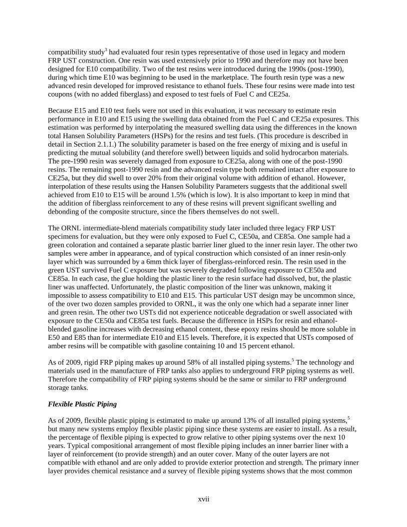
Because E15 and E10 test fuels were not used in this evaluation, it was necessary to estimate resin
performance in E10 and E15 using the swelling data obtained from the Fuel C and CE25a exposures. This
estimation was performed by interpolating the measured swelling data using the differences in the known
total Hansen Solubility Parameters (HSPs) for the resins and test fuels. (This procedure is described in
detail in Section 2.1.1.) The solubility parameter is based on the free energy of mixing and is useful in
predicting the mutual solubility (and therefore swell) between liquids and solid hydrocarbon materials.
The pre-1990 resin was severely damaged from exposure to CE25a, along with one of the post-1990
resins. The remaining post-1990 resin and the advanced resin type both remained intact after exposure to
CE25a, but they did swell to over 20% from their original volume with addition of ethanol. However,
interpolation of these results using the Hansen Solubility Parameters suggests that the additional swell
achieved from E10 to E15 will be around 1.5% (which is low). It is also important to keep in mind that
the addition of fiberglass reinforcement to any of these resins will prevent significant swelling and
debonding of the composite structure, since the fibers themselves do not swell.
The ORNL intermediate-blend materials compatibility study later included three legacy FRP UST
specimens for evaluation, but they were only exposed to Fuel C, CE50a, and CE85a. One sample had a
green coloration and contained a separate plastic barrier liner glued to the inner resin layer. The other two
samples were amber in appearance, and of typical construction which consisted of an inner resin-only
layer which was surrounded by a 6mm thick layer of fiberglass-reinforced resin. The resin used in the
green UST survived Fuel C exposure but was severely degraded following exposure to CE50a and
CE85a. In each case, the glue holding the plastic liner to the resin surface had dissolved, but, the plastic
liner was unaffected. Unfortunately, the plastic composition of the liner was unknown, making it
impossible to assess compatibility to E10 and E15. This particular UST design may be uncommon since,
of the over two dozen samples provided to ORNL, it was the only one which had a separate inner liner
and green resin. The other two USTs did not experience noticeable degradation or swell associated with
exposure to the CE50a and CE85a test fuels. Because the difference in HSPs for resin and ethanol-
blended gasoline increases with decreasing ethanol content, these epoxy resins should be more soluble in
E50 and E85 than for intermediate E10 and E15 levels. Therefore, it is expected that USTs composed of
amber resins will be compatible with gasoline containing 10 and 15 percent ethanol.
As of 2009, rigid FRP piping makes up around 58% of all installed piping systems.5 The technology and
materials used in the manufacture of FRP tanks also applies to underground FRP piping systems as well.
Therefore the compatibility of FRP piping systems should be the same or similar to FRP underground
storage tanks.
Flexible Plastic Piping
As of 2009, flexible plastic piping is estimated to make up around 13% of all installed piping systems,5
but many new systems employ flexible plastic piping since these systems are easier to install. As a result,
the percentage of flexible piping is expected to grow relative to other piping systems over the next 10
years. Typical compositional arrangement of most flexible piping includes an inner barrier liner with a
layer of reinforcement (to provide strength) and an outer cover. Many of the outer layers are not
compatible with ethanol and are only added to provide exterior protection and strength. The primary inner
layer provides chemical resistance and a survey of flexible piping systems shows that the most common

xviii
inner permeation barrier material is polyvinylidene difluoride (PVDF). Other plastics used as permeation
barriers are nylons and polyethylene terephthalate (PET). PVDF, PET, and several grades of nylon were
evaluated in the ORNL intermediate-blends study along with the other plastic materials that were exposed
to Fuel C and CE25a. As with the UST resins, the performance (volume swell) with exposure to E10 and
E15 was estimated using the measured volume swelling for exposure to Fuel C and CE25a and the known
HSPs for these materials. The resulting analysis indicates that flexible piping permeation barrier materials
will not have added significant swell (less than 1%) when moving from E10 to E15. Therefore, the
increase in risk associated with leaking when switching from E10 to E15 will be low.
Elastomers, Sealants, Couplings and Fittings
Couplings and fittings used to connect piping, the submersible turbine pump, and valves represent one of
the highest potential locations for leaking in UST systems. There are two potential locations/sources of
leaks associated with fittings. One is where the coupling attaches to the piping and the other one is at the
fitting-to-fitting seal interface. In many (but not all) cases fluorocarbons are used as interfacial seals
between fittings. Fluorocarbons have been shown to be compatible with ethanol and it is unlikely that a
properly installed fluorocarbon elastomer will leak when exposed to either E10 or E15. For metal and
some rigid FRP piping systems, pipe thread sealants may be employed to seal fittings via threaded
attachments. Some legacy pipe thread sealants were shown to be incompatible with gasoline containing
10% aggressive ethanol and would clearly not be acceptable for E15 use either. Newer engineered
products (such as fluoroelastomers) have been developed for ethanol-blended gasoline and these sealants
have been shown to be compatible with gasoline containing up to 25% aggressive ethanol.
For flexible piping systems a stainless steel coupling is normally compression fitted to the outer surface
of the pipe so the leak potential is very low for properly installed couplings. In contrast fittings attached to
rigid FRP systems typically utilize an adhesive to maintain a seal between the coupling and the outer pipe
wall. Adhesives designed for fuel ethanol use are available. This material type was not included in the
ORNL intermediate-blend study and its performance in either E10 or E15 was not ascertained. For rigid
FRP pipe-to-pipe joining, fiberglass reinforced resin is also frequently applied to the joined ends in a butt-
and-wrap arrangement. Since the wrapping is composed of fiberglass-reinforced resin similar to the
piping itself, the leak potential with exposure to E15 for a properly installed joint should be low since the
increase of swell associated with E15 (relative to E10) is estimated to be small (1.5%). It is important to
note that the joined sections have lower structural integrity (mechanical strength) than the pipe as a
whole, but should not leak as a primary result of the fuel exposure.
E.4 Conclusions
In general, the materials used in existing UST infrastructures would not be expected to exhibit
compatibility concerns when moving from E10 to E15. The volume swell and hardness results of tested
polymer materials were not significantly different when exposed to either CE10a or CE15a, although
significant changes were observed when these fuels are compared to the E0 formulation. The indication is
that UST systems were affected by switching from E0 to E10. However, since E10 and E15 produce
similar results, compatibility is not expected to be altered noticeably when moving from E10 to E15. The
metallic materials showed negligible corrosion as long as phase separation did not occur. If an aqueous
phase is formed, then the possibility for aggressive corrosion exists. Therefore, the proper application of
biocides and water monitoring is likely to be more critical at preventing corrosion for gasoline fuel
containing ethanol.

1
1. INTRODUCTION
1.1 HISTORY AND BACKGROUND
In the United States oil dependence is driven primarily by the transportation sector. Transportation
accounts for 69% of the total oil consumption in the United States, and the industry itself is around 90%
oil dependent (and the remainder being natural gas, propane, electric and ethanol).6 In 2008 the average
daily oil consumption equivalent used the U.S. transportation sector was approximately 14 million
barrels. This rate is projected to increase to around 16 million barrels per day by 2025.7 Currently, the
bulk of our oil usage is provided by other countries as foreign oil imports and makes up around 57% of
the total oil usage.8 This dependency impacts our nation’s security, since our oil supply is determined
partly by other countries, some of whom are not friendly to the United States. Foreign disruption has been
shown to negatively impact the nation’s economy and makes the U. S. more vulnerable during times of
international crisis.
The Energy Independence and Security Act (EISA) of 2007 was enacted by Congress to move the nation
toward increased energy independence by increasing the production of renewable fuels to meet its
transportation energy needs. The law establishes a new renewable fuel standard (RFS) that requires the
nation to use 36 billion gallons annually (2.3 million barrels per day) of renewable fuel in its vehicles by
2022. Ethanol is the most widely used renewable fuel in the United States, and its production has grown
dramatically over the past decade. According to EISA and RFS, ethanol (produced from corn as well as
cellulosic feedstocks) will make up the vast majority of the new renewable fuel requirements. However,
ethanol use limited to E10 and E85 (in the case of flex fuel vehicles or FFVs) will not meet this target.
Even if all of the E0 gasoline dispensers in the country were converted to E10, such sales would represent
only about 15 billion gallons per year.9 If 15% ethanol, rather than 10% were used, the potential would be
up to 22 billion gallons. The vast majority of ethanol used in the United States is blended with gasoline to
create E10, that is, gasoline with up to 10 % ethanol. The remaining ethanol is sold in the form of E85, a
gasoline blend with as much as 85% ethanol that can only be used in FFVs. Although the U. S.
Department of Energy (DOE) remains committed to expanding the E85 infrastructure, that market will
not be able to absorb projected volumes of ethanol in the near term. Given this reality, DOE and others
have begun assessing the viability of using intermediate ethanol blends as one way to transition to higher
volumes of ethanol.
In October of 2010, the U. S. Environmental Protection Agency (EPA) granted a partial waiver to the
Clean Air Act allowing the use of fuel that contains up to 15% ethanol for the model year 2007 and newer
light-duty motor vehicles. This waiver represents the first of a number of actions that are needed to move
toward the commercialization of E15 gasoline blends. On January 2011, this waiver was expanded to
include model year 2001 light-duty vehicles, but specifically prohibited use in motorcycles and off-road
vehicles and equipment.2
UST stakeholders generally consider fueling infrastructure materials designed for use with E0 to be
adequate for use with E10, and there are no known instances of major leaks or failures directly
attributable to ethanol use. It is conceivable that many compatibility issues, including accelerated
corrosion, do arise and are corrected onsite and, therefore do not lead to a release. However, there is some
concern that higher ethanol concentrations, such as E15 or E20, may be incompatible with current
materials used in standard gasoline fueling hardware. In the summer of 2008, DOE recognized the need to
assess the impact of intermediate blends of ethanol on the fueling infrastructure, specifically located at the
fueling station. This includes the dispenser and hanging hardware, the underground storage tank, and
associated piping.

2
The DOE program has been co-led and funded by the Office of the Biomass Program and Vehicle
Technologies Program with technical expertise from the Oak Ridge National Laboratory (ORNL) and the
National Renewable Energy Laboratory (NREL). The infrastructure material compatibility work has been
supported through strong collaborations and testing at Underwriters Laboratories (UL). ORNL performed
a compatibility study investigating the compatibility of fuel infrastructure materials to gasoline containing
intermediate levels of ethanol. These results can be found in the ORNL report entitled Intermediate
Ethanol Blends Infrastructure Materials Compatibility Study: Elastomers, Metals and Sealants (hereafter
referred to as the ORNL intermediate blends material compatibility study).3 These materials included
elastomers, plastics, metals and sealants typically found in fuel dispenser infrastructure.
The test fuels evaluated in the ORNL study were SAE standard test fuel formulations used to assess
material-fuel compatibility within a relatively short timeframe. Initially, these material studies included
test fuels of Fuel C, CE10a, CE17a, and CE25a. The CE17a test fuel was selected to represent E15 since
surveys have shown that the actual ethanol upper limit can be as high as 17%. Later, CE50a and CE85a
test fuels were added to the investigation and these results are being compiled for a follow-on report to be
published in 2012. Fuel C was used as the baseline reference and is a 50:50 blend of isooctane and
toluene. This particular composition was used to represent premium-grade gasoline and was also used as
the base fuel for the ethanol blends, where it is denoted by “C” in the fuel name. The level of ethanol is
represented by the number following the letter E. Therefore a 10% blend of ethanol in Fuel C is written as
CE10a, where “a” represents an aggressive formulation of the ethanol that contains water, NaCl, acetic
and sulfuric acids per the SAE J1681 protocol.
1.2 ETHANOL COMPATIBILITY AND SOLUBILITY
Pure ethanol, by itself, is not generally considered corrosive toward most metallic materials; however, as
a polar molecule, ethanol will be more susceptible to having compatibility issues with both metals and
polymers due to (1) increased polarity relative to gasoline, (2) adsorption of water, and (3) a higher
solubility potential relative to gasoline. The first two factors are relevant to metals and alloys, while the
latter affects primarily polymers. The corrosion potential is directly related to the electrical conductivity
of a solution. Kirk10
measured the electrical conductivity for gasoline as a function of ethanol
concentration and dissolved water level. A plot of the electrical conductivity as a function of ethanol
concentration in gasoline is shown in Fig. 1. As shown in the figure, the electrical conductivity is low for
ethanol-blended gasoline increases marginally with ethanol concentrations up to 20%. However, although
the conductivity numbers are low, relatively speaking, E15 is 10 times more conductive than E10. As the
ethanol concentration increases from 20% to 50%, the corresponding conductivity increases by almost
two orders of magnitude. As a result, metal corrosion becomes a significant concern for gasoline blends
containing 50% or more ethanol.

3
Fig. 1. Electrical conductivity of gasoline as a function of ethanol concentration. Source: D. W. Kirk,
Fuel 62, 1512–1513 (December 1983).
The level of dissolved water also has a pronounced effect. The results in Fig. 2 show the effect of water
concentration in addition to ethanol level. In this figure, the electrical conductivity (listed as S in Fig. 2
and 1/Ω in Fig. 1) is plotted for blends containing 5, 10, 15, 20, 30 and 40% ethanol by volume. As the
level of ethanol increases, the conductivity curves for each blend increase as well, and for each set of
curves the conductivity also increases with the level of dissolved water. In fact, the water solubility limit
increases the conductivity by an order of magnitude when going from E10 to E15. In addition, water itself
is a solvent for NaCl and acids, which can lead to even higher rates of corrosion.
Ethanol also affects the material-fluid mutual solubility associated with the fuel blend, which is an
important parameter for gauging the compatibility of fuels with polymers. The influence of the solubility
parameter is complex; however, solvents and solutes having similar solubility parameters will have a
greater affinity for permeation and dissolution.11
The solubility parameter, or more specifically, the
difference in parameters between the solute (polymer) and solvent (fuel), is important in predicting and
understanding the solubility of a system. As the solubility parameter values for the solute and solvent
converge, the propensity for the two components to mix (or allow the solvent to permeate into the solute)
becomes thermodynamically possible. For an elastomer or plastic, this effect will be an increase in
swelling of the polymer.
0.00E+00
5.00E-06
1.00E-05
1.50E-05
2.00E-05
2.50E-05
3.00E-05
3.50E-05
0 10 20 30 40 50 60
Co
nd
uc
tivit
y, 1
/Ω-m
Ethanol concentration, vol%

4
Fig. 2. Electrical conductivity of gasoline as a function of
ethanol and water content. Source: D. W. Kirk, Fuel 62, 1512–1513
(December 1983).
A simplified representation of solubility as a function of ethanol concentration in gasoline is shown in
Fig. 3. The wide shaded horizontal band in the chart represents the range of solubility parameters,
expressed as total Hansen Solubility Parameter (HSP) for many dispenser polymers, especially
elastomers. Epoxies, such as those used as the matrix materials for underground storage tanks, have a
total HSP value around 24(MPa)1/2
, which is noticeably higher than the HSP for polymers. The
implication for UST resins is that the solubility of the epoxy in the fuel will be highest for gasoline
containing around 80% ethanol.
As the ethanol concentration increases from zero to 15%, it effectively raises the solubility parameter and
approaches the solubility parameter of most dispenser polymers. Therefore, the propensity for the fuel to
permeate into and dissolve polymeric components is enhanced. It is important to note that, in reality,
solubility is determined from multiple thermodynamic factors, and that the highest level of mutual
solubility for a given polymer does not necessarily match precisely with the theoretically-derived
parameters which have been simplified in Fig. 3. Standard gasoline fuel delivery systems contain
elastomeric materials having excellent compatibility and stability with hydrocarbon fuels. However, the
ethanol molecule is relatively small and highly polar due to the –OH group. In addition the tendency to
introduce hydrogen bonding is high. These features enable ethanol’s permeation into and interaction with

5
the elastomer structure, which can result in swelling and softening of elastomers. Another negative feature
associated with permeation is that soluble components, especially plasticizers added to impart flexibility
and durability in the elastomer, may be leached out, thereby affecting the mechanical properties of the
compounded elastomer component and degrading the ability of the component to perform its intended
function.
Fig. 3. Total Hansen Solubility Parameter as a function of ethanol concentration. The lower
blue horizontal band represents the solubility range of many UST system elastomer and plastics. The
upper blue band is representative of FRP resins.
Several studies have been undertaken to evaluate the compatibility of ethanol with engine materials,
especially those used in fuel system components such as pumps, and much of this work has recently
focused on the intermediate E15, E20, and E25 blends.12–15
However, little work had been reported on the
compatibility of these fuels to standard fuel dispenser materials, which subsequently became the focus of
the ORNL-led materials compatibility study noted earlier.
1.3 FUELING DISPENSER MATERIALS AND ETHANOL COMPATIBILITY STUDY
As part of the ORNL intermediate-blend materials compatibility study, an extensive survey was
performed to identify to the extent possible all materials used in the fueling dispenser infrastructure. A list
of the materials identified and evaluated in the ORNL study is shown in Table 1, where those materials
identified by the authors of this report for use in UST systems are highlighted. Most of the plastic
materials are used as structural components in FRP tanks and in both FRP and flexible piping systems.
The elastomeric materials most identified as seals and gaskets are Viton™ and Dyneon™ brand
fluorocarbons, but NBR and rubberized cork may still be in use in legacy tank probes and overfill
devices. Steel is used in tanks and piping and aluminum is also used in some applications, such as drop
tubes.
10
15
20
25
30
0 10 20 30 40 50 60 70 80 90 100
Tota
l Hansen S
olu
bili
ty P
ara
mete
r, (M
Pa)1
/2
Ethanol concentration in gasoline, vol.%
21-50% Ethanol
HSP value of FRP resins
Range of HSP values for UST sytem polymers

6
It is important to note that while the researchers were able to discover and identify an extensive list of
relevant materials over the course of this and other studies, it is possible, if not probable, that other
materials used in legacy, and some new infrastructure systems, were not included in this investigation.
Table 1. List of materials evaluated in intermediate ethanol blends compatibility study. (Materials identified
as being used in UST systems are highlighted.)
Metals/Alloys Elastomers Plastics Sealants
304 stainless steel
1020 carbon steel
1100 aluminum
Cartridge brass
Phosphor bronze
Nickel 201
Terne-plated steel
Galvanized steel
Cr-plated brass
Cr-plated steel
Ni-plated
Ni-plated steel
Viton™ fluorocarbon
Dyneon™ fluorocarbon
Acrylonitrile butadiene
rubber (NBR)
Silicone rubber
Fluorosilicone rubber
Neoprene rubber
Styrene butadiene rubber
(SBR)
Polyurethane
Rubberized cork
High density polyethylene (HDPE)
Fluorinated HDPE
Polypropylene (PP)
Polyoxymethylene
Nylon
Polyvinylidene fluoride (PVDF)
Polytetrafluoroethylene (PTFE)
Polyphenylene sulfide (PPS)
Polyethylene terephthalate (PET)
Polybutylene terephthalate (PBT)
Polythiourea
Isophthalic ester resin
Terephthalic ester resin
Vinyl ester resin
Epoxy resin
PTFE-based
sealants (two-types)
with and without
Teflon™ tape
Of the all the test fuels investigated (Fuel C, CE10a, CE17a, CE25a, CE50a and CE85a), only the metal
and elastomeric materials were subjected to each fuel type. The plastics were originally exposed to Fuel C
and CE25a (and later to CE50a and CE85a) and the sealants were evaluated only in Fuel C, CE10a and
CE25a. At a later point in this study, ORNL received sections of fiberglass USTs removed from use.
Three UST sections were cut into test specimens and added to the final exposure runs of Fuel C, CE50a,
and CE85a.
The test protocol consisted of immersing the specimen coupons in the test fuels and vapors for extended
periods, 4 weeks for metals and elastomers and 16 weeks for plastics. During the exposure period the fuel
temperature was maintained at 60oC in order to maintain consistency with the UL Subject 87A-E25 test
standard used in by Underwriter Laboratories when assessing fuel compatibility.16
2. UNDERGROUND TANKS & PIPING SYSTEMS
Underground fuel storage tanks are composed either of steel or fiberglass reinforced plastic. Both of these
materials, as well as flexible plastic, are also used in piping systems. A breakdown of the piping types
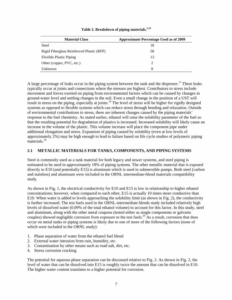
using an analysis based on 22 state databases,5 is shown in Table 2. The overwhelming majority of
installed piping (~71%) is either flexible or rigid fiberglass reinforced plastic. Of the remaining metal
systems, approximately 18% of metal piping systems are steel. Copper makes around 2% of underground
piping and approximately 8% is of unknown material construction.19
The most common installed piping
systems are rigid FRP and flexible plastic systems. Older piping systems were typically single-walled, but
most newly installed systems are double-walled. FRP makes up approximately 58% of installed piping,
while flexible plastic piping accounts for around 13% of all installed piping systems.5
7
Table 2. Breakdown of piping materials.5,19
Material Class Approximate Percentage Used as of 2009
Steel 18
Rigid Fiberglass Reinforced Plastic (RFP) 58
Flexible Plastic Piping 13
Other (copper, PVC, etc.) 2
Unknown 8
A large percentage of leaks occur in the piping system between the tank and the dispenser.17
These leaks
typically occur at joints and connections where the stresses are highest. Contributors to stress include
movement and forces exerted on piping from environmental factors which can be caused by changes in
ground-water level and settling changes in the soil. Even a small change in the position of a UST will
result in stress on the piping, especially at joints.18
The level of stress will be higher for rigidly designed
systems as opposed to flexible systems which can reduce stress through bending and relaxation. Outside
of environmental contributions to stress, there are inherent changes caused by the piping materials’
response to the fuel chemistry. As stated earlier, ethanol will raise the solubility parameter of the fuel so
that the resulting potential for degradation of plastics is increased. Increased solubility will likely cause an
increase in the volume of the plastic. This volume increase will place the component pipe under
additional elongation and stress. Expansion of piping caused by solubility (even at low levels of
approximately 2%) may be high enough to lead to failure based on life cycle studies of polymeric piping
materials.18
2.1 METALLIC MATERIALS FOR TANKS, COMPONENTS, AND PIPING SYSTEMS
Steel is commonly used as a tank material for both legacy and newer systems, and steel piping is
estimated to be used in approximately 18% of piping systems. The other metallic material that is exposed
directly to E10 (and potentially E15) is aluminum which is used in submersible pumps. Both steel (carbon
and stainless) and aluminum were included in the ORNL intermediate-blend materials compatibility
study.
As shown in Fig. 1, the electrical conductivity for E10 and E15 is low in relationship to higher ethanol
concentrations; however, when compared to each other, E15 is actually 10 times more conductive than
E10. When water is added to levels approaching the solubility limit (as shown in Fig. 2), the conductivity
is further increased. The test fuels used in the ORNL-intermediate blends study included relatively high
levels of dissolved water (0.09% of the total ethanol volume) to account for this factor. In this study, steel
and aluminum, along with the other metal coupons (tested either as single components or galvanic
couples) showed negligible corrosion from exposure to the test fuels.20
As a result, corrosion that does
occur on metal tanks or piping systems is likely due to one of more of the following factors (none of
which were included in the ORNL study):
1. Phase separation of water from the ethanol fuel blend
2. External water intrusion from rain, humidity, etc.
3. Contamination by other means such as road salt, dirt, etc.
4. Stress corrosion cracking
The potential for aqueous phase separation can be discussed relative to Fig. 2. As shown in Fig. 2, the
level of water that can be dissolved into E15 is roughly twice the amount that can be dissolved in E10.
The higher water content translates to a higher potential for corrosion.
8
2.2 POLYMER PIPING AND TANK SYSTEMS
As shown in Table 2, the majority of underground piping is constructed from plastic materials, which are
categorized as two types, flexible piping and FRP piping. Although FRP systems are more established in
the field, the majority of new piping systems installed today are flexible plastic systems because these
systems are easier to install. As a result, the percentage of flexible piping is expected to grow relative to
the other piping systems over the next 10 years. The piping arrangement can consist of either single- or
double-walled systems. The majority of installed single-walled piping systems are legacy units, but new
requirements are resulting in increased use of double-walled piping systems. Double-walled systems have
an interstitial space between the walls that can be monitored for leaks.
2.2.1 Flexible Plastic Piping
Typical compositional arrangement of flexible piping includes an inner barrier liner within a layer of fiber
reinforcement (to provide strength) and a cover to protect the inner layers from damage from handling
and to prevent water intrusion. We surveyed the materials used in the construction of the outer wall for
double wall plastic-based systems. In virtually every case, the outer wall is composed of inexpensive
materials, known to be less chemically resistant to ethanol.
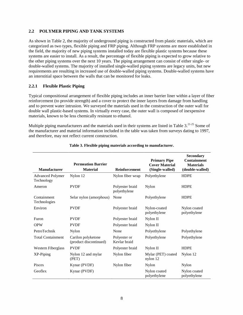
Multiple piping manufacturers and the materials used in their systems are listed in Table 3.21-25
Some of
the manufacturer and material information included in the table was taken from surveys dating to 1997,
and therefore, may not reflect current construction.
Table 3. Flexible piping materials according to manufacturer.
Manufacturer
Permeation Barrier
Material Reinforcement
Primary Pipe
Cover Material
(Single-walled)
Secondary
Containment
Materials
(double-walled)
Advanced Polymer
Technology
Nylon 12 Nylon fiber wrap Polyethylene HDPE
Ameron PVDF Polyester braid
polyethylene
Nylon HDPE
Containment
Technologies
Selar nylon (amorphous) None Polyethylene HDPE
Environ PVDF Polyester braid Nylon-coated
polyethylene
Nylon coated
polyethylene
Furon PVDF Polyester braid Nylon II
OPW PVDF Polyester braid Nylon II
PetroTechnik Nylon None Polyethylene Polyethylene
Total Containment Carilon polyketone
(product discontinued)
Polyester or
Kevlar braid
Polyethylene Polyethylene
Western Fiberglass PVDF Polyester braid Nylon II HDPE
XP-Piping Nylon 12 and mylar
(PET)
Nylon fiber Mylar (PET) coated
nylon 12
Nylon 12
Pisces Kynar (PVDF) Nylon fiber Nylon Nylon
Geoflex Kynar (PVDF) Nylon coated
polyethylene
Nylon coated
polyethylene
9
Of the flexible pipes reported in Table 3, the majority had inner barrier layers composed of PVDF. The
three remaining designs incorporated nylon, either as nylon 12, Selar™ amorphous nylon, or a
combination of nylon 12 and Mylar™ PET. For most systems the permeation barrier layer was externally
reinforced with wound fibers composed of either nylon or polyester. This reinforcement, in turn, is
usually coated with nylon or polyethylene. Likewise, the most common materials used for the outer wall
are polyethylene and nylon.
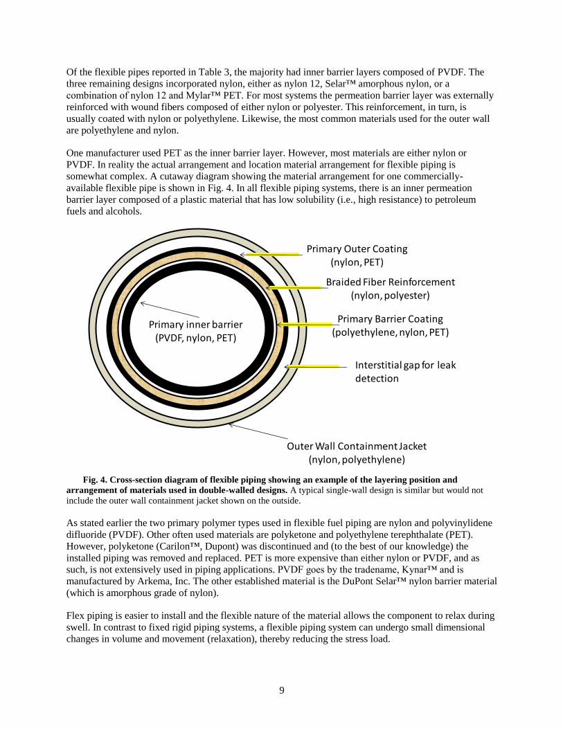
One manufacturer used PET as the inner barrier layer. However, most materials are either nylon or
PVDF. In reality the actual arrangement and location material arrangement for flexible piping is
somewhat complex. A cutaway diagram showing the material arrangement for one commercially-
available flexible pipe is shown in Fig. 4. In all flexible piping systems, there is an inner permeation
barrier layer composed of a plastic material that has low solubility (i.e., high resistance) to petroleum
fuels and alcohols.
Fig. 4. Cross-section diagram of flexible piping showing an example of the layering position and
arrangement of materials used in double-walled designs. A typical single-wall design is similar but would not
include the outer wall containment jacket shown on the outside.
As stated earlier the two primary polymer types used in flexible fuel piping are nylon and polyvinylidene
difluoride (PVDF). Other often used materials are polyketone and polyethylene terephthalate (PET).
However, polyketone (Carilon™, Dupont) was discontinued and (to the best of our knowledge) the
installed piping was removed and replaced. PET is more expensive than either nylon or PVDF, and as
such, is not extensively used in piping applications. PVDF goes by the tradename, Kynar™ and is
manufactured by Arkema, Inc. The other established material is the DuPont Selar™ nylon barrier material
(which is amorphous grade of nylon).
Flex piping is easier to install and the flexible nature of the material allows the component to relax during
swell. In contrast to fixed rigid piping systems, a flexible piping system can undergo small dimensional
changes in volume and movement (relaxation), thereby reducing the stress load.
Primary inner barrier(PVDF, nylon, PET)
Primary Barrier Coating(polyethylene, nylon, PET)
Braided Fiber Reinforcement(nylon, polyester)
Primary Outer Coating(nylon, PET)
Outer Wall Containment Jacket(nylon, polyethylene)
Interstitial gap for leak detection
10
The ORNL intermediate blends compatibility study included samples of representative flexible pipe
materials. These materials include PET, HDPE, nylon 6, nylon 6/6, nylon 11, and nylon 12. (Selar, which
is an amorphous grade of nylon, was not evaluated.) These nylon grades are differentiated by the degree
of molecular alignment (crystallinity), additives, and processing. In contrast to the other types, Nylon 11
is a unique specialty grade made from vegetable oil. Although Selar™ nylon was not specifically
included among the test coupons, according to DuPont, its chemical resistance is comparable to other
grades of synthetic nylon (nylon 6, 6/6, and 12).26
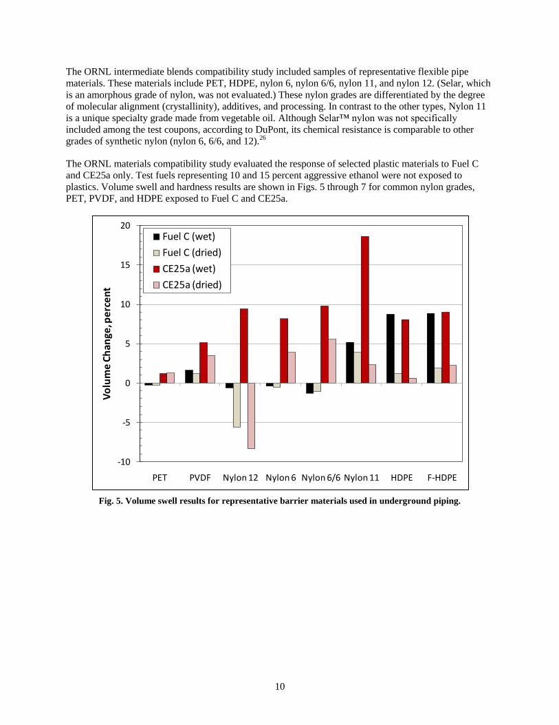
The ORNL materials compatibility study evaluated the response of selected plastic materials to Fuel C
and CE25a only. Test fuels representing 10 and 15 percent aggressive ethanol were not exposed to
plastics. Volume swell and hardness results are shown in Figs. 5 through 7 for common nylon grades,
PET, PVDF, and HDPE exposed to Fuel C and CE25a.
Fig. 5. Volume swell results for representative barrier materials used in underground piping.
-10
-5
0
5
10
15
20
PET PVDF Nylon 12 Nylon 6 Nylon 6/6 Nylon 11 HDPE F-HDPE
Vo
lum
e C
han
ge, p
erc
en
t
Fuel C (wet)
Fuel C (dried)
CE25a (wet)
CE25a (dried)

11
Fig. 6. Absolute hardness results for representative barrier materials used in flexible piping.
Fig. 7. Point change in hardness (from baseline) for representative barrier materials
used in flexible piping.
0
10
20
30
40
50
60
70
80
90
100
PET PVDF Nylon 12 Nylon 6 Nylon 6/6 Nylon 11 HDPE F-HDPE
Har
dn
ess
(Sh
ore
D),
po
ints
Baseline
Fuel C (wet)
Fuel C (dried)
CE25a (wet)
CE25a (dried)
-20
-15
-10
-5
0
5
10
PET PVDF Nylon 12 Nylon 6 Nylon 6/6 Nylon 11 HDPE F-HDPE
Po
int C
han
ge in
Har
dn
ess
Fuel C (wet)
Fuel C (dried)
CE25a (wet)
CE25a (dried)

12
As shown in Fig. 5, PET and PVDF experienced the lowest low volume swell (1.23% and 5.12%,
respectively) following exposure to CE25a. In contrast, the nylon 6, nylon 6/6, and nylon 12, along with
the HDPE samples swelled between 8 and 10 %. The highest level of volume swell occurred for nylon 11,
and was around 18 %. Following dry out, these materials retained some fluid, as evidenced by the residual
swell present in the dried samples. The one exception is nylon 12, which shrank from its original volume
to over 5% from exposure to Fuel C and around 8% with CE25a. Such shrinkage is evidence that Fuel C
and CE25a were able to dissolve and remove a significant portion of the solid material. The hardness
results presented in Figs. 6 and 7 show that nylon 12 and nylon 11 both became softer with exposure to
CE25. The decrease in hardness of nylon 12 was around 7 points, which is only marginally higher than
the softening of the nylon 6, nylon 6/6 and the HDPE samples. However, nylon 11 dropped 17 points and
this drop coupled with the high volume swell suggests that nylon 11 may not be acceptable for use in
plastic piping, even for E0 formulations.
Although E10 and E15 test fuels were not evaluated, an estimation of the volume swell can be made using
solubility parameters (obtained from the literature) and volume swell results in CE25a. Volume swell is a
measurement of solubility. According to solubility theory, the difference between the solubility
parameters is inversely related to the solubility between the solute (plastic) and solvent (test fuel). In other
words, the closer match between the total Hansen Solubility Parameters of the solute and solvent, the
more mutually soluble they are to each other. Using the known total HSP values for the plastic materials
and E25, E15 and E10, and the measured volume swell in CE25a (as shown in Table 4), a calculated
volume swell for each material in E15 and E10 can be made using the ratio of the differences in the total
Hansen solubility parameters between the plastic and CE25a to the HSP difference between the plastic
and CE15 and CE10. These calculated values are shown in Table 5.
The method for calculation of volume swell is as follows:
VS(EX) = VS(E25) (1-(ΔHSP(EX) –ΔHSP(E25)))/ (ΔHSP(EX))
Where:
VS(EX) is the volume swell of the plastic sample after exposure to a fuel containing X percent of
ethanol by volume.
VS(E25) is the volume swell of the plastic in CE25a
ΔHSP(EX) is the difference between the total Hansen Solubility Parameter values for the plastic and the
fuel containing X volume percent ethanol
ΔHSP(25) is the difference between the total Hansen Solubility Parameter values for the plastic and the
fuel containing 25 volume percent ethanol

13
Table 4. Volume swell results for representative barrier materials used in flexible underground piping
Plastic Hansen Solubility Parameter (MPa1/2
) Volume Swell in CE25a (%)
PVDF 23.17 5.12
Nylon 6 20.3 8.15
Nylon 12 22.2 9.40
PET 20.8 1.23
Fuel Type Hansen Solubility Parameter (MPa1/2
)
E25 18.58
E15 17.59
E10 17.09
Table 5. Measured and calculated results for PVDF and Nylon 6
Barrier
material
HSP
(MPa1/2
)
Measured volume
swell (CE25a)
Calc. Volume
Swell for E15
Calc. Volume
Swell for E10
Estimated vol.
increase associated
with increasing
ethanol from E10 to
E15
PVDF 23.17 5.12 4.1 3.6 0.5
Nylon 6 20.3 8.15 5.2 4.4 0.8
Nylon 12 22.2 9.4 7.4 6.7 0.7
PET 20.8 1.23 0.8 0.7 0.1
The results in Table 5 show that the expected increase in volume swell when going from E10 to E15 is
less than 1 percent for the primary barrier liner materials used in flexible piping. The low additional
volume swell is not likely to create much stress in the piping since these materials are able to relax due to
the flexible nature of the piping. Based on these results, we do not anticipate any noticeable potential for
release associated with going from E10 to E15. However, if the piping is rigidly constrained somehow,
then stress buildup may occur to cause bucking (or cracking) of the piping. Most of the changes in swell
(and hardness) will occur from moving from E0 to E10.
2.2.2 Fiber-reinforced Plastic Tanks & Piping
Fiber-reinforced plastic piping materials, design and construction are similar to those used in fiberglass
tanks. The construction consists of first placing resin on a mandrel and later adding fiber reinforced resin
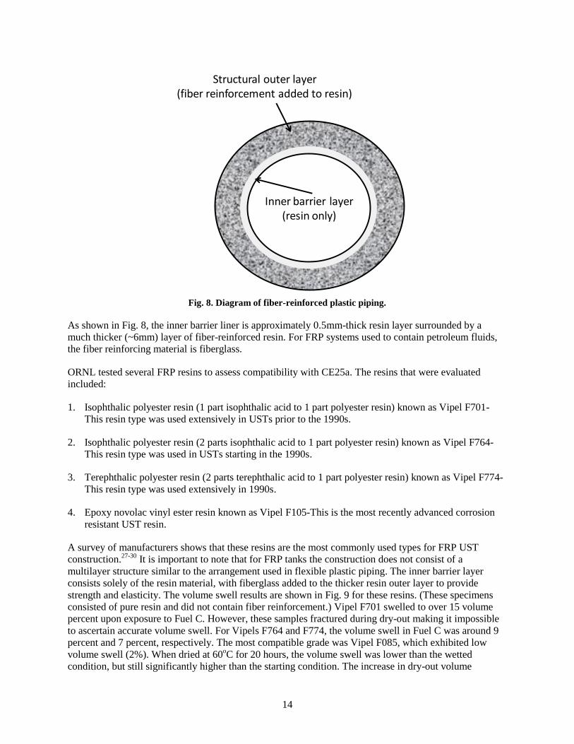
to serve as the outer layer. A diagram showing layering and arrangement is depicted in Fig. 8.
14
Fig. 8. Diagram of fiber-reinforced plastic piping.
As shown in Fig. 8, the inner barrier liner is approximately 0.5mm-thick resin layer surrounded by a
much thicker (~6mm) layer of fiber-reinforced resin. For FRP systems used to contain petroleum fluids,
the fiber reinforcing material is fiberglass.
ORNL tested several FRP resins to assess compatibility with CE25a. The resins that were evaluated
included:
1. Isophthalic polyester resin (1 part isophthalic acid to 1 part polyester resin) known as Vipel F701-
This resin type was used extensively in USTs prior to the 1990s.
2. Isophthalic polyester resin (2 parts isophthalic acid to 1 part polyester resin) known as Vipel F764-
This resin type was used in USTs starting in the 1990s.
3. Terephthalic polyester resin (2 parts terephthalic acid to 1 part polyester resin) known as Vipel F774-
This resin type was used extensively in 1990s.
4. Epoxy novolac vinyl ester resin known as Vipel F105-This is the most recently advanced corrosion
resistant UST resin.
A survey of manufacturers shows that these resins are the most commonly used types for FRP UST
construction.27-30
It is important to note that for FRP tanks the construction does not consist of a
multilayer structure similar to the arrangement used in flexible plastic piping. The inner barrier layer
consists solely of the resin material, with fiberglass added to the thicker resin outer layer to provide
strength and elasticity. The volume swell results are shown in Fig. 9 for these resins. (These specimens
consisted of pure resin and did not contain fiber reinforcement.) Vipel F701 swelled to over 15 volume
percent upon exposure to Fuel C. However, these samples fractured during dry-out making it impossible
to ascertain accurate volume swell. For Vipels F764 and F774, the volume swell in Fuel C was around 9
percent and 7 percent, respectively. The most compatible grade was Vipel F085, which exhibited low
volume swell (2%). When dried at 60oC for 20 hours, the volume swell was lower than the wetted
condition, but still significantly higher than the starting condition. The increase in dry-out volume
Inner barrier layer(resin only)
Structural outer layer(fiber reinforcement added to resin)

15
compared to the initial condition indicates that significant levels of Fuel C are contained within the resin.
This fact is further illustrated in Fig. 10 which shows the corresponding mass change of the specimens
before and after dry-out.
Fig. 9. Volume swell results for UST resins following exposure to Fuel C and CE25a.
Fig. 10. Mass change for UST resins following exposure to Fuel C and CE25a.
0
5
10
15
20
25
30
F701 F764 F774 F085
Pe
rce
nt V
olu
me
Ch
ange
(Sw
ell
) Fuel C (wet)
Fuel C (dry)
CE25a (wet)
CE25a (dry)
Pre 1990s resin Post 90s resin Post 90s resin Advanced resin
0
5
10
15
20
25
F701 F764 F774 F085
Pe
rce
nt M
ass
Ch
ange
Fuel C (wet)
Fuel C (dry)
CE25a (wet)
CE25a (dry)
Pre 1990s resin Post 90s resin Post 90s resin Advanced resin

16
Upon exposure to CE25a, Vipels F774 and F085 exhibited high degrees of swelling. F774 swelled to 26%
while F085 swelled to around 23%. However, because the resins are reinforced with glass fibers, the
actual swelling of the composite structure will be considerably lower. The inner barrier liner will be more
susceptible to expansion, but the fiberglass reinforcement will prevent outward expansion of the resin
barrier layer. However, inward expansion may occur and this effect may result in softening or cracking,
or other forms of damage. It is important to note that the specimens which cracked in the test fuels (Vipel
F701 and F764) were composed of pure resin, and these resins are not designed for use without fiberglass
reinforcement. Fiberglass, by itself, is insoluble and is used in composite structures to provide modulus
and strength. Fiberglass reinforcement would resist fuel permeation and elongation in the composite
structure. As a result the level of swell in FRP systems would be expected to be much lower than for the
pure resin. However, the inner barrier layer of an FRP tank (or FRP piping) is not reinforced and may
experience degradation in the form of softening, spalling, or cracking.
The estimated volume swell for Vipel F774 and Vipel F085 in E10 and E15 was calculated using the
Hansen Solubility Parameter-based method employed for estimating the volume swell for the flexible
plastic materials. These results are shown in Table 6, and show that for the Vipel F774 and F085 resins,
the difference in calculated volume swell associated with E10 and E15 is low (around 1.5% for both resin
types). This means that in all likelihood there will be minimal effect when moving from E10 to E15.
However, there is potential for a big difference when moving from E0 to E10.
Table 6. Measured and calculated results for UST resins Vipel F774 and Vipel F085
Resin
material
HSP
(MPa1/2
)
Measured volume
swell (CE25a)
Calc. Volume
Swell for E15
Calc. Volume
Swell for E10a
Estimated vol.
increase associated
with increasing
ethanol from E10 to
E15
Vipel F774 24.1 25.99 22.0 20.5 1.5
Vipel F085 24.1 22.99 19.5 18.1 1.4
The change in hardness results for the UST resins are shown in Fig. 11. For each resin type, the hardness
dropped slightly with exposure to Fuel C, but CE25a was shown to significantly lower hardness in the
wetted condition. Vipel F701 and Vipel F764 exhibited greatest drop hardness (31 and 20 points,
respectively) from the original condition. These values are considered high and since hardness is a
measure of strength and elastic modulus, it is not surprising that these two specimens exhibited fracture
following exposure to CE25a. Interestingly, Vipel F774 also experienced a relatively large decrease in
hardness of around 15 points. The combination of reduced volume swell and lower change in hardness
(relative to the F701 and F764 resins) were enough to prevent fracture of the F774 resin. The most
advanced resin grade, Vipel F085 exhibited the least change in hardness of the resins tested.

17
Fig. 11. Point change in hardness for the UST resin samples following exposure to Fuel C and
CE25a.
Vipel F701 was used extensively in fiberglass reinforced USTs prior to 1990.25
As such, it was designed
primarily for gasoline use only and was not optimized for compatibility with ethanol-blended fuel. The
volume swell and hardness decrease upon exposure to Fuel C would be considered acceptable for this
resin type. F701 was replaced with more ethanol-resistant grades during the 1990s. Any legacy tanks
composed of F701, or similar resin type, may be subject to ethanol degradation. Although the 30-year
warrantee on tanks composed of F701 would have expired by now, many of these tanks are still in use.
During the 1990s, many of the isophthalic resins were replaced by terephthalic-based and epoxy vinyl
resins for improved performance.28
The data provided by the materials compatibility testing shows that
the terephthalic and vinyl resins are better suited for ethanol compatibility.
The ORNL intermediate-blend study also evaluated coupons taken from FRP underground storage tanks
that had been removed from service. These tanks were cut into sections and sent to ORNL for evaluation.
Photographs showing these specimens before and after exposure to the test fuels are shown in Figs. 12,
13, and 14. In each figure the baseline represents the unexposed sample.
Unfortunately the resin formulation of the UST sections was unknown, but the tanks were most likely
pre-1990s vintage. Therefore, the resin formulations used in these tanks may not have been designed for
use with ethanol-blended fuel. Over one dozen tanks were sectioned and sent to ORNL. All, except one,
of these USTs were of amber coloration, similar to the pure resin coupons that were discussed previously,
and nearly identical in appearance. There was one set of tank sections that was unique in that it was the
only UST to have a corrugated plastic film adhered to the inner surface and was dark green in coloration.
Test coupons were cut from three UST sections, which were labeled Batch 1, Batch 2, and Batch 3. Both
-35
-30
-25
-20
-15
-10
-5
0
F701 F764 F774 F085
Po
int C
han
ge in
Har
dn
ess
Fuel C (wet)
Fuel C (dry)
CE25a (wet)
CE25a (dry)
Pre 1990s resin Post 90s resin Post 90s resin Advanced resin
18
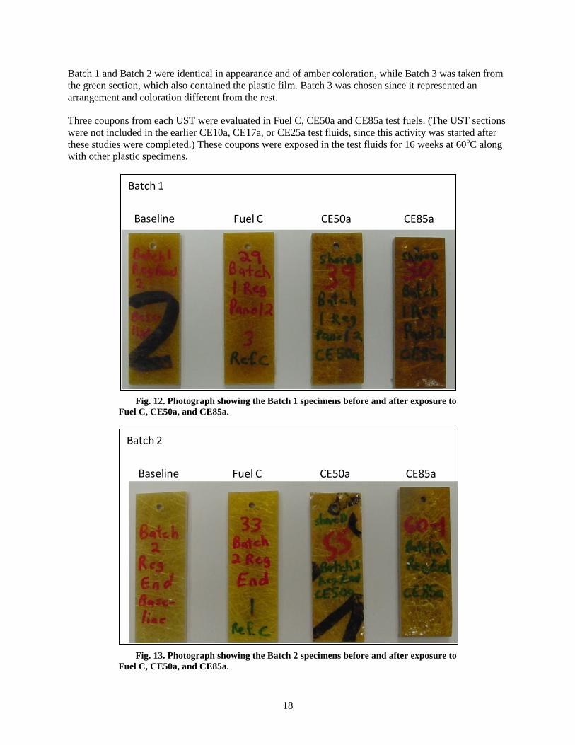
Batch 1 and Batch 2 were identical in appearance and of amber coloration, while Batch 3 was taken from
the green section, which also contained the plastic film. Batch 3 was chosen since it represented an
arrangement and coloration different from the rest.
Three coupons from each UST were evaluated in Fuel C, CE50a and CE85a test fuels. (The UST sections
were not included in the earlier CE10a, CE17a, or CE25a test fluids, since this activity was started after
these studies were completed.) These coupons were exposed in the test fluids for 16 weeks at 60oC along
with other plastic specimens.
Fig. 12. Photograph showing the Batch 1 specimens before and after exposure to
Fuel C, CE50a, and CE85a.
Fig. 13. Photograph showing the Batch 2 specimens before and after exposure to
Fuel C, CE50a, and CE85a.
Baseline Fuel C CE50a CE85a
Batch 1
Baseline Fuel C CE50a CE85a
Batch 2

19
Fig. 14. Photograph showing the Batch 3 specimens before and after exposure
to Fuel C, CE50a, and CE85a.
The photographs shown in Figs. 12 and 13 reveal that the amber resin specimens (Batch 1 and Batch 2)
did not experience any observable degradation (outside of a slight change in color) from exposure to
ethanol. However, the Batch 3 specimens (shown in Fig. 14) experienced massive degradation from the
CE50a and CE85a test fuels. For this design, the corrugated liner was debonded by the Fuel C and the
aggressive ethanol fuels. Interestingly, this liner survived exposure to the test fuels. However, the inner
resin layer was removed and the resin surrounding the fiberglass reinforcement had dissolved to the
extent that the fibers were completely exposed. It is important to note that, as depicted in Fig. 3, epoxy-
based resins are likely to be more soluble in CE50a and CE85a fuels than for intermediate E10 and E15
levels. Therefore it is expected that the Batch 1 and Batch 2 USTs will be compatible to gasoline
containing intermediate levels of ethanol. However, if the corrugated liner of the Batch 3 UST was
damaged or breached, then it is likely that this UST has a high risk of leaking.
3. ELASTOMERS, SEALANTS, COUPLINGS AND FITTINGS
3.1 ELASTOMERS
Although elastomers are ubiquitous in fuel dispenser components, especially as hoses and seals, they are
not used extensively as primary piping materials in either FRP or flexible piping systems. However, these
elastomers could be used as gaskets and seals in the submersible tank pump head. A survey of piping and
coupling manufacturers listed Viton fluorocarbon as the only o-ring material sold today for use in
couplings and fittings for gasoline delivery systems.31
Other elastomer types were not mentioned as
coupling materials for current and new UST piping systems, although they may be prevalent in legacy
systems. Of the elastomers evaluated in the ORNL intermediate-blend materials compatibility study,
fluorocarbons were found to be the most compatible to ethanol. The other elastomers, in particular nitrile
rubbers (NBRs), showed moderate but significant increases (10-12%) in swell and increased softening
with exposure to aggressive ethanol as shown in Fig. 15. However, the additional increase associated with
CE17a exposure (compared to CE10a) was small (5 to 8%).
Baseline Fuel C CE50a CE85a
Batch 3
20
Fig. 15. Volume swell and point change in hardness for elastomers exposed to Fuel C,
CE10a, CE17a and CE25a.
During dry-out, elastomers such as NBR and neoprene exhibit moderate shrinkage and embrittlement (see
Fig. 16) which is attributed to extraction of the plasticizer components. However the level of shrinkage or
mass reduction associated is constant and independent of ethanol content. As a result, the increase in leak
potential among the elastomers when moving from E10 to E15 is expected to be low. However, these
materials (especially NBR, neoprene, and SBR) will exhibit a high increase in swell when moving from
E0 to E10 (or E15). Therefore, care must be taken when placing ethanol-blended gasoline into a system
that had only contained gasoline.
-60.0
-50.0
-40.0
-30.0
-20.0
-10.0
0.0
0.0 20.0 40.0 60.0 80.0 100.0 120.0 140.0 160.0P
oin
t C
ha
ng
e i
n W
et
Ha
rdn
es
s
Wet Volume Swell, percent
Change in Wet Hardness vs Volume Swell
Fuel C
CE10a
CE17a
CE25a
SBR
SiliconeNeoprene
Fluorocarbons
& Fluorosilicone
Polyurethane
NBRs
NBR 1NBR 1

21
Fig. 16. Percent mass change and point change in hardness for elastomers exposed to
Fuel C, CE10a, CE17a and CE25a following dry-out.
It is important to note that these elastomers are used solely as seals (i.e., o-rings, gaskets, etc.) and are not
utilized as structural materials for UST systems. Additional swell for o-rings and gaskets in some cases
does not degrade seals or diminish sealing potential, and may, to a small degree, improve the performance
of the seal. These materials are not recommended for use as structural components of piping and UST
systems, since even moderate levels of swell will create internal stresses which, even at low levels, can
significantly reduce the lifecycle and durability of a component.
3.2 PIPE THREAD SEALANTS
Pipe thread sealants are used for metal piping and some FRP piping systems. Standard PTFE sealants
(such as RectorSeal™) were originally developed for E0 use and were used extensively in legacy piping
systems. These sealants have been shown to be incompatible for use with alcohols. In the ORNL
intermediate-blend materials compatibility study, RectorSeal™ was shown to be incompatible with
CE10a. This result strongly indicates that the pipe thread sealants used in the E0 legacy systems
experienced leaking when exposed to E10. Ethanol compatible sealants such as GasOila ESeal™ were
subsequently developed for ethanol-blended gasoline use and are now the industry standard. The ORNL
study showed that the GasOila ESeal™ product is compatible with fuel containing up to 25 percent
aggressive ethanol. It is very likely that the standard PTFE sealants used in the legacy systems were
replaced with the ethanol-compatible products during the implementation of E10. There is no hard data to
support this assessment, but based on the development and widespread use of the GasOila product, it
appears to be the case. Except for polyurethane (which is used as a coating rather than as a seal), the
elastomers and sealants evaluated in the ORNL intermediate-blend materials study showed no significant
increase in swell and softening when moving from E10 to E15. Therefore, we do not foresee any added
potential for releases when switching from E10 to E15.
-15
-10
-5
0
5
10
15
20
-20.0 -15.0 -10.0 -5.0 0.0 5.0
Po
int
Ch
an
ge
in
Ha
rdn
es
s (
Dry
)
Percent Mass Change
Change in Hardness and Mass Change After Drying
Fuel C
CE10a
CE17a
CE25a
FluorocarbonsSiliconeSBR
NBRs
Neoprene
Polyurethane
NBR 1
Fluorosilicone

22
3.3 COUPLINGS AND FITTINGS
One of the most susceptible locations of the underground storage tank systems are the couplings used to
connect piping, fittings, and valves. There are two potential sources of leaks. One is where the coupling
attaches to the piping and the other one is at the seal interface mating two couplings together. The
interfacial seal issue was discussed under the elastomer section and is not considered to be a significant
point of release if seals and gaskets are made of fluorocarbon materials and are properly installed.
Flexible plastic piping typically utilizes swage-type fittings to join piping and connect valves and flanges.
A typical coupling assembly consists of a stainless steel insert with one or two o-rings, a stainless steel
ferrule with one o-ring, and a swivel nut (or other means) to compress the ferrule against the outer pipe
surface.31
A simplified schematic is shown in Fig. 17. The compression of the plastic between the
stainless steel insert and ferrule maintains a leak tight seal. In this configuration, the fuel is only exposed
to the plastic piping, stainless steel coupling and the o-ring used to seal the coupling adjacent faces.
Newer units were found to utilize fluorocarbon as the o-ring material, although legacy couplings may use
other elastomers (such as NBR). These couplings usually require a special tool (from the piping supplier)
to install properly. It is important to note that couples for FRP piping cannot be installed in this manner
because the hard resin would fracture under high compression.
Fig. 17. Simplified schematic showing attachment of a coupling to flexible plastic
piping.
The two most common methods for joining FRP piping and attaching couplings are adhesive bonding and
butt and strap joints.32
The butt and strap method is considered the most reliable means for joining FRP
piping. Two pieces of pipe are butted together and layers of chopped fiberglass are wrapped around the
pipe in a resin matrix similar to the pipe composition. A diagram depicting a butt and strap joint is shown
in Fig. 18. If the butt and strap materials are similar or identical to the pipe materials, then compatibility
performance is expected to be essentially the same and thus potential for further degradation due to E15 is
minimal.
Stainless steel insert
Pipe wall Ferrule
Compression nut presses ferrule against pipe wall
Compression nut Couplingface
O-ring
Zone of compression

23
Fig. 18. Schematic diagram of the butt and strap joint.
The adhesive method involves adding an adhesive to glue a fitting or coupling to FRP. Because of its
inherent weakness, this method is not used to join pipe sections, but is restricted to attaching fittings (such
as flanges). Typically the outer surface of the pipe is sanded to allow better distribution of the sealant and
to enable the adhesive to better grip the pipe surface and thereby form a strong mechanical bond. One
application of this method is shown in Fig. 19. The adhesive maintains a seal between the fitting and the
pipe end. At the fitting face, the adhesive will be exposed to fuel in the crevice region between the
adjacent pipe ends. For some applications, the outer pipe walls are tapered at the ends to enable better fit
between the pipe wall and fitting.
Fig. 19. Schematic showing a common arrangement of using adhesive on FRP piping.
The adhesives used for FRP systems contain a mix of inorganics (over 50%), such as clay, limestone, and
silica and a mix of hydrocarbons.33
The inorganic fraction imparts strength, rigidity and is resistant to
attack from aggressive fuel components (including alcohols). The remaining hydrocarbons consist
primarily of acrylic polymers, resins and distillate products. Information pertaining to adhesive resistance
to ethanol was lacking and we were not able to ascertain ethanol compatibility.
Pipe wall
FittingLaminated fiberglass resin seal
Pipe wall
Fitting
Adhesive
O-ring
Fluid will move into the gap between the pipe wall faces and have direct contact with adhesive

24
4. CONCLUSIONS
The USEPA Office of Underground Storage Tanks commissioned a study at ORNL to evaluate whether
an increased potential for leaking of USTs will occur when moving from E10 to E15 fuel. The original
intention was to construct a probabilistic failure analysis tool to estimate the increase in releases, if any, if E15 replaced E10 in regulated UST systems. A key part of this process was to solicit opinions from a
panel of industry and regulatory experts to identify critical variables that impact failure likelihood
estimates. However, the lack of information on the performance of existing UST systems with E15
precluded the possibility that state/industry experts could speculate on E15’s impact to UST systems.
Therefore, the project objective was redirected to address the added leak potential (or incompatibility) of
UST system materials when moving from E10 to E15. The data used to make this assessment were
obtained primarily from the ORNL intermediate blend compatibility study. This study included metal and
polymeric materials typically used in UST systems, and these materials were evaluated in aggressive test
fuel formulations representing E0, E10, E15, E25, E50 and E85. Potential leak locations, such as pipe
couplings were identified, and the elastomers and sealants used in couplings and joining were also
studied.
4.1 CONCLUSION ON TANKS AND PIPING MATERIALS
Metallic materials included carbon and stainless steel and aluminum. A large number of USTs are
composed of carbon steel, which is also used in approximately 18% of piping. Stainless steel is used in
pipe couplings which are used to join piping sections and fittings. Aluminum, while not used as
extensively as either carbon or stainless steels, is used in the construction of submersible pumps.
However, failure of a submersible pump should not lead to leaking. The results from the ORNL
intermediate-blends compatibility study showed that carbon and stainless steels, and aluminum will not
undergo significant corrosion in either E10 or E15. However, it is important to note that the test
conditions for these materials did not include stress or water-phase separation, both of which can
contribute to increased corrosivity. In fact, if aqueous phase separation occurs, then the risk for corrosion
will be higher for E15 since the maximum level of dissolved water is roughly twice that of E10.
Plastics are used extensively in underground piping systems. The two types of plastic piping, flexible and
FRP, employ different types and grades of plastic materials. Flexible piping is primarily composed of
various grades of nylon, PVDF, PET, polyester, and polyethylene. These materials were only tested in
Fuel C and CE25a. As a result, the volume change, associated with CE10a and CE15a exposure, was
estimated using the known swelling behavior at CE25a and Hansen Solubility Parameters for the plastics
and test fuels. Nylon 11 exhibited the highest level of swelling (~18%) and would likely not be
considered acceptable for use in USTs or flexible piping systems. Likewise, nylon 12 also may not be
acceptable due to the significant loss of mass after drying. Other plastics, such as HDPE, F-HDPE, nylon
6 and nylon 6/6 exhibited relatively high swell (8-10%) and may not be suitable when switching from E0
to either E10 or E15. However, the calculated swell for nylon 6, nylon 6/6, PVDF, PET, and polyethylene
indicated that the added increase in swell when moving from E10 to E15 was very low. This result
suggests that the leak potential in E15 for flexible piping containing these materials will be low as well.
The performance of resins used in the construction of FRP tanks and piping is highly dependent on the
type of resin. A pre-1990 legacy isophthalic polyester resin was visibly damaged with exposure to a test
fuel containing 25% aggressive ethanol. Analysis of post-1990s resins (exposed to CE25a) were mixed;
the resin composed of isophthalic polyester was damaged, while the resins composed of terephthalic
polyester or vinyl ester were not. Interestingly, the two resins that were damaged from exposure to
ethanol were both isophthalic polyesters. Based on these results, isophthalic polyester resins should be
avoided in the construction of UST systems storing ethanol-blended fuels. The predicted level of volume

25
swell associated with E10 and E15 was calculated for the terephthalic polyester and vinyl ester resins.
The results suggest that the added volume swell associated with E15 (compared to E10) is extremely low
and would not likely increase the potential for leaking with E15 fuel. ORNL was able to include three
legacy UST samples in a later compatibility effort using CE50a and CE85a as test fuels. In one unique
case, a legacy FRP UST that contained a separate plastic liner exhibited significant degradation of the
resin material when exposed to high levels of ethanol. Although the liner was not visibly damaged, its
performance with lower intermediate levels of ethanol-blended gasoline could not be ascertained. The
other two UST sections were not damaged and would likely exhibit good compatibility with E10 or E15.
4.2 CONCLUSION ON ELASTOMERS, SEALANTS, COUPLINGS AND FITTINGS
A high leak potential also exists where piping sections are joined and fittings are attached. The structural
material typically used in these applications is stainless steel and the sealing materials are either
elastomers and/or pipe thread sealants. Modern joining units employ primarily fluorocarbons in o-ring
and sealing applications; however some legacy systems may use NBRs and other elastomer types. The
ORNL intermediate-blend ethanol compatibility study investigated the performance of fluorocarbons,
fluorosilicone, NBRs, silicone rubber, styrene butadiene rubber, neoprene and polyurethane. These
elastomers all showed significant swelling with exposure to ethanol. However, because elastomers are
used solely as seals (i.e., o-rings, gaskets, etc.), swelling is not necessarily an indication of leak potential.
Additional swell for o-rings and gaskets may improve the performance of the seal. Except for
polyurethane (which is used as a coating rather than as a seal), the elastomers and sealants evaluated in
the ORNL intermediate-blend materials study showed no significant increase in swell and softening when
moving from E10 to E15. Therefore, for field applications and materials examined in this study, there
should not be any corresponding potential for releases associated with increase the ethanol concentration
in fuel gasoline from E10 to E15. The flanges used in coupling systems are composed of stainless steel
and this material has been shown to have excellent compatibility with ethanol-blended fuels.
Pipe thread sealants are used for metal piping and some FRP piping systems. Standard PTFE sealants
(such as RectorSeal™), used in E0 applications, were shown to be incompatible for use with E10.
However, ethanol-compatible sealants (such as GasOila ESeal™) were compatible with fuel containing
up to 25 percent aggressive ethanol. Although it is very likely that standard PTFE sealants used in legacy
systems were replaced with the ethanol-compatible products during the implementation of E10, there may
be systems still in use with the incompatible sealant material.
FRP piping joined using either a butt and strap configuration or an adhesive is used to secure a fitting on
one end. The butt and strap consists of a FRP wrap that contains resin similar or identical to the FRP pipe
resin, and therefore, should be compatible with ethanol-blended fuel. Adhesives consist of a mix of
various organic and inorganic materials, and we could not assess their compatibility to ethanol since they
were not included in the ORNL intermediate-ethanol blends compatibility study.
In general, several materials evaluated in this study were found to not perform well in fuel blends
containing ethanol. These materials demonstrated incompatibility with E10 and should not be used for
E15 (unless it can be demonstrated that a particular polymer grade is, in fact, compatible). Systems most
susceptible to increased leakage will be those legacy USTs which are currently using E0 and will be
switching directly to E15.
5. REFERENCES
1. Energy Independence and Security Act of 2007: A Summary of Major Provisions, CRS Report for
Congress, Order Code RL34294, December 21, 2007.

26
2. USEPA Website: www.epa.gov/otaq/regs/fuel/additive/e15.#wn
3. Intermediate Ethanol Blends Infrastructure Materials Compatibility Study, M. Kass et al., ORNL TM-
2010/326, March 2011
4. Society of Automotive Engineers, “Gasoline, Alcohol, and Diesel Fuel Surrogates for Materials
Testing,” SAE J1681, issued September 1993, revised January 2000-01.
5. Review of the UST Equipment in Use at the Time of the Review in 22 states from all 10 EPA
Regions, TO_3003_TDD_5_Phase_2_Equipment_Analysis Summary_-_8-5-09.xls, provided by EPA
to ORNL on October 12, 2010.
6. DOE/EIA Annual Energy Review 2008, DOE/EIA-0384(2008), June 2009, www.eia.doe.gov/aer.
7. Energy Information Administration, EIA Energy Outlook 2009, DOE/EIA-0484(2009), May 2009,
www.eia.doe.gov.
8. U.S. Energy Information Administration, EIA Petroleum Supply Monthly, February 2009.
9. U.S. Energy Information Administration, EIA Annual Energy Outlook 2010, December 2009.
10. D. W. Kirk, Fuel 62, 1512–1513 (December 1983).
11. C. M. Hansen, Hansen Solubility Parameters: A User’s Handbook, 2nd Edition, CRC Press, Taylor&
Francis Group, Boca Raton, Florida, 2007.
12. B. H. West et al., Effects of Intermediate Ethanol Blends on Legacy Vehicles and Small Non-road
Engines, Report 1, ORNL/TM-2008/117, October 2008.
13. B. Jones, G.Mead, P. Steevens, and C. Connors, The Effects of E20 on Elastomers Used in
Automotive Fuel System Components, Minnesota Center for Automotive Research, Minnesota State
University, Mankato, February 22, 2008.
14. G. Davis and C. Hoff, “The Effect of Using Ethanol-blended Gasoline on the Performance and
Durability of Fuel Delivery Systems in Classic Automobiles,” SAE Paper No. 2010-01-2135.
15. H. Jafari et al., Effect of Ethanol as Gasoline Additive on Vehicle Fuel Delivery System Corrosion,
Materials and Corrosion 61(5), 432–440 (May 2010).
16. Ken Boyce and Tom Chapin, Dispensing Equipment Testing with Mid-Level Ethanol/Gasoline Test
Fluid, Document No. 10807, NREL/SR-7A20-49187. November 2010.
17. Underground Storage Tank Systems: Parts and Pieces Demystified, Ben Thomas, Petroleum Training
Solutions Webinar for Oak Ridge National Laboratory, June 29, 2010.
18. Fatigue and Tribological Properties of Plastics and Elastomers, W. Andrew, William Andrew
Publishing, 1995.
19. Brian Knapp, American Petroleum Institute, personal communication (2011).
20. S. J. Pawel, M. D. Kass, and C. J. Janke, Preliminary Compatibility Assessment of Metallic Dispenser
Materials for Service in Ethanol Fuel Blends, ORNL/TM-2009/286.

27
21. Survey of Flexible Piping Systems by ICF Incorporated (Fairfax, VA) for the USEPA, March 1997.
22. A Practical Primer for UST Piping Applications, Andy Youngs, Petroleum Equipment & Technology
Archive, February 1999.
23. What Specifiers Need to Look for in Flexible Piping, Andy Youngs, Petroleum Equipment &
Technology Archive, May 1998.
24. Technologies used in Today’s Flexible Piping Systems, Andy Youngs, Petroleum Equipment &
Technology Archive, July 1998.
25. Flexible-pipe Concerns Drive Home the Need for Tank-owner Vigilance, LUSTline Bulletin 42,
October 2002.
26. DuPont technical sheet for Selar and nylon 6.
www2.dupont.com/Selar/en_US/assets/downloads/selar_pa3426_nylon_blends.pdf
27. Smith Fiberglass: RED THREAD IIa: www.smithfiberglass.com/UL Piping.htm
28. Scott Lane, AOC Resins: personal communication (2011)
29. Fibre reinforced polymers for corrosion control, Michael Stevens: www.engineerlive.com
30. Corrosion Resistant Resins for Chemical Containment and Piping: Range and Specification, Scott
Bader (2008): www.scottbader.com/downloads/ChemicalContainment_Apr08.pdf
31. Flexible Underground Piping Manual, OPW Fueling Containment Systems, Product Manual,
Publication Number: UPM-0001. April 28, 2011.
32. Fiberglass Reinforced Plastic (FRP) Piping Systems: A Comparison of Two Joining Methods, the
Adhesive Bonded Joint vs the Butt & Strap Method, EDO Specialty Plastics, Engineering Series ES-
010, October, 2001.
33. Fiberbond Piping Systems, http://es.is.itt.com/FiberbondFiberglass.htm
