analysis of vibration assisted drilling –a · pdf fileanalysis of vibration assisted...
TRANSCRIPT
http://doi.org/10.24867/JPE-2017-01-001
1
JPE (2017) Vol.20 (1) Review Paper
Reddy, Y.R.M., Prasad, B.S.
ANALYSIS OF VIBRATION ASSISTED DRILLING –A BASE FOR TOOL PERFORMANCE EVALUATION
Received: 10 February 2017 / Accepted: 30 April 2017
Abstract: The primary aim of present work is to evaluate the performance of tungsten carbide (uncoated), and HSS (high-speed steel) twist drill bits in vibration-assisted drilling. Another important objective of the present work is to investigate the effects of process parameters on vibration amplitude, (i.e., displacement) in the drilling of aerospace alloys like Ti-6Al-4V and Al7075. Effect of workpiece hardness, cutting speed, feed rate, and the number of holes drilled on tool wear is also examined in dry machining. As per the full factorial design technique, experimental tests conducted on a radial drilling machine. A Laser Doppler Vibrometer used for acquiring the vibration signals occurred during the drilling process. The vibration displacement determined by FFT (Fast Fourier Transform) algorithm. It observed that at all cutting conditions (tested), tungsten carbide drill clearly outperformed HSS (High-Speed Steel) Drill. Results of this work can use as a basis for the real-time capable tool condition monitoring system in vibration-assisted drilling. Key words: Drilling, vibration, tool wear, drill tool, Ti-6Al-4V, Al7075, tool condition monitoring. Analiza bušenja potpomognuta vibracijama- osnova za ocenu rada alata. Primarni cilj ovog rada je da procene performanse alata za izradu burgije potpomognute vibracijama od tvrdog metala (nepresvučen), i BČ (brzorezni čelik). Još jedan važan cilj ovog rada je da se ispita uticaj procesnih parametara na amplitudu vibracije (tj, pomeranje) pri bušenju legura za avio industriju kao sto su Ti-6Al-4V i Al7075. Ispitivan je uticaj tvrdoće obradka, brzine rezanja, kapaciteta punjenja, kao i broj izbušenih rupa na habanje alata pri suvoj obradi. Prema punom faktornom planu exsperimenta izvedeni su eksperimentalni testovi na radijalnoj bušilici. Laserski Dopler Vibrometer korišćen je za izazivanje vibracija tokom procesa bušenja. Analiza vibracija vršena je pomoću FFT (Fast Fourier Transform) algoritam. Primetno je da je u svim uslovima pri rezanju (testiranim), burgija od tvrdog metala nadmašila burgiju od BČ. Rezultati ovog rada se mogu koristiti kao osnova za monitoring stanja alata u realnom vremenu pri obradi bušenjem uz pomoć vibracija. Ključne reči: Bušenje, vibracija, habanje alata, burgija, Ti-6Al-4V, Al7075, monitoring stanja alata. 1. INTRODUCTION
The titanium alloy Ti–6Al–4V and aluminum alloy
Al7075 used for a variety of applications in aerospace and chemical industries because of their properties such as high strength to weight ratio and excellent corrosion resistance [1]. In the present day scenario, the titanium alloys are extensively used in aerospace structure as they have the best combination of metallurgical and physical properties, in addition to its lightweight. However, due to the low thermal conductivity of titanium and its alloy, the temperature at the tool/workpiece interface increases, which results in poor machinability that can affect the tool life [2]. Nowadays, cutting processes play an enormous role in supporting the economies of developing countries. The process of drilling holes constituted one-third of machining work and applied as the finished operation in aerospace and automobile industries [3]. Ease of the application and economic aspects associated with drilling are the main reason behind the selection of drilling as part of machining methods for the manufacturing of various industrial products. Drilled holes come in different forms, in which through hole is drilled entirely throughout the workpiece as a blind hole is drilled only to a certain depth. The failure of a twist drill occurs by
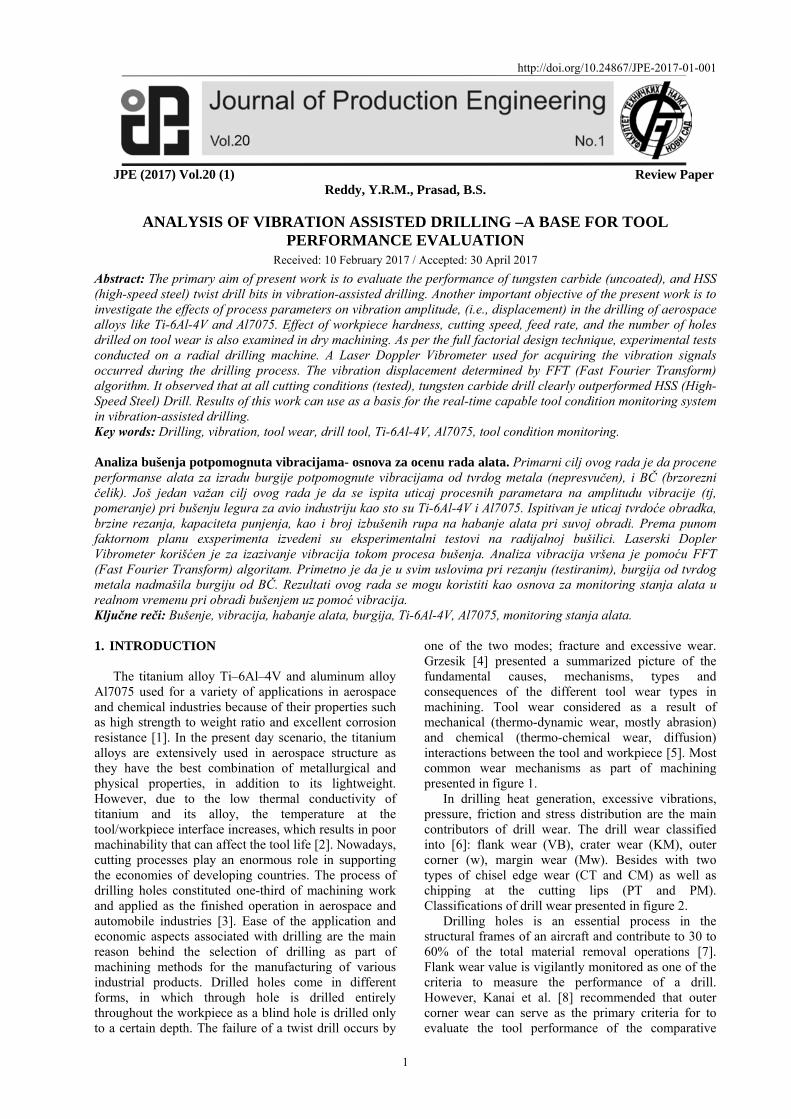
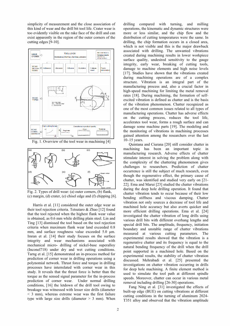
one of the two modes; fracture and excessive wear. Grzesik [4] presented a summarized picture of the fundamental causes, mechanisms, types and consequences of the different tool wear types in machining. Tool wear considered as a result of mechanical (thermo-dynamic wear, mostly abrasion) and chemical (thermo-chemical wear, diffusion) interactions between the tool and workpiece [5]. Most common wear mechanisms as part of machining presented in figure 1. In drilling heat generation, excessive vibrations, pressure, friction and stress distribution are the main contributors of drill wear. The drill wear classified into [6]: flank wear (VB), crater wear (KM), outer corner (w), margin wear (Mw). Besides with two types of chisel edge wear (CT and CM) as well as chipping at the cutting lips (PT and PM). Classifications of drill wear presented in figure 2.
Drilling holes is an essential process in the structural frames of an aircraft and contribute to 30 to 60% of the total material removal operations [7]. Flank wear value is vigilantly monitored as one of the criteria to measure the performance of a drill. However, Kanai et al. [8] recommended that outer corner wear can serve as the primary criteria for to evaluate the tool performance of the comparative
2
simplicity of measurement and the close association of this kind of wear and the drill bit tool life. Crater wear is too evidently visible on the rake face of the drill and can exist apparently in the region of the outer corners of the cutting edges [9-10].
Fig. 1. Overview of the tool wear in machining [4]
Fig. 2. Types of drill wear: (a) outer corners, (b) flank, (c) margin, (d) crater, (e) chisel edge and (f) chipping [6].
Harris et al. [11] considered the outer edge wear as their tool rejection criteria. Tetsutaro & Zhao [12] found that the tool rejected when the highest flank wear value is obtained, as 0.6 mm while drilling plain steel. Lin and Ting [13] dismissed the tool based on the tool rejection criteria when maximum flank wear land exceeded 0.8 mm, and surface roughness value exceeded 5.0 μm. Imran et al. [14] their study focuses on the surface integrity and wear mechanisms associated with mechanical micro- drilling of nickel-base superalloy (Inconel718) under dry and wet cutting conditions. Tarng et al. [15] demonstrated an in-process method for prediction of corner wear in drilling operations using a polynomial network. Thrust force and torque in drilling processes have interrelated with corner wear in this study. It reveals that the thrust force is better than the torque as the sensed signal parameter for the in-process prediction of corner wear. Under normal drilling conditions, [16] the letdown of the drill tool owing to breakage was witnessed with lesser size drills (diameter < 3 mm), whereas extreme wear was the first failure type with large size drills (diameter > 3 mm). When
drilling compared with turning, and milling operations, the kinematic and dynamic structures were more or less similar, and the chip flow and the distribution of cutting temperatures were the same. In drilling, the chip formation occurs in a closed area, which is not visible and this is the major drawback associated with drilling. The unwanted vibrations created during machining results in lower workpiece surface quality, undesired sensitivity to the gauge integrity, early wear, breaking of cutting tools, damage to machine elements and high noise levels [17]. Studies have shown that the vibrations created during machining operations are of a complex structure. Vibration is an integral part of the manufacturing process and, also a crucial factor in high-speed machining for limiting the metal removal rates [18]. During machining, the formation of self-excited vibration is defined as chatter and is the basis of the vibration phenomenon. Chatter recognized as one of the most common issues related to all types of manufacturing operations. Chatter has adverse effects on the cutting process, reduces the tool life, accelerates tool wear, forms a rough surface and can damage some machine parts [19]. The modeling and the monitoring of vibrations in machining processes gained attention among the researchers over the last 10–15 years.
Quintana and Ciurana [20] still consider chatter in machining has been an important topic in manufacturing research. Adverse effects of chatter stimulate interest in solving the problem along with the complexity of the chattering phenomenon gives challenges to researchers. Prediction of chatter occurrence is still the subject of much research, even though the regenerative effect, the primary cause of chatter, was identified and studied very early on [21-22]. Ema and Marui [23] studied the chatter vibrations during the deep hole drilling operation. It found that chatter vibration tends to occur because of their low bending stiffness and viscous damping. Chatter vibration not only sources a decrease of tool life and machined hole accuracy but also averts quicker and more efficient drilling operations. Ema et al. [24] investigated the chatter vibration of long drills using various drill bits with different overhang lengths and special drill bits. The amplitude, frequency, initiation boundary and unstable range of chatter vibrations measured at various cutting parameters. The experimental results showed that the vibration is a regenerative chatter and its frequency is equal to the natural bending frequency of the drill when the drill point supported in a machined hole. Based on the experimental results, the stability of chatter vibration discussed. Mehrabadi et al. [25] presented the investigations on chatter vibration occurring in drills for deep hole machining. A finite element method is used to simulate the tool path at different spindle speeds. Moreover, chatter can occur in various metal removal including drilling [26-30] operations.
Fang Ning et al. [31] investigated the effects of built-up edge (BUE) on cutting vibrations at different cutting conditions in the turning of aluminum 2024- T351 alloy and observed that the vibration amplitude
3
was affected by the cutting speed, the feed rate, and their interaction. According to their findings, there exist three distinct BUE regions, characterized by different patterns of cutting vibrations. Abuthakeer et al. [32] investigated the effects of spindle vibrations on surface roughness by using an artificial neural network (ANN) in the dry turning of Al6063 aluminum workpiece material. Rahim et al. [33] investigated the performance of uncoated carbide tools in the high-speed drilling of the Ti6Al4V alloy. Machining responses of the drilling process such as vibration, thrust force, chip formation, and torque examined at different test conditions. It apparently found that cutting speed and feed rate significantly influenced machining responses. Dornfeld et al. [34] investigated the effects of tool geometry and process parameters on drilling burr formation of Ti-6Al-4Vusing carbide drills with and without coolant, and high-speed cobalt drills without coolant. Performance evaluation of high-speed steel (HSS) tools presented under different test conditions. The main wear mechanisms critically analyzed with scanning electron microscope and also identified adhesion, and abrasive wear on flank face, besides, BUE at chisel and cutting edges [35]. Sakurai et al. [36] have investigated the tool life, burr shape, and chips formation under different cutting strategies in drilling using coated drills. Machinability study of Ti–6Al4V using short length drills of high-speed steel discussed.
Khanna et al. [37] present the use of Taguchi approach for better tool wear rate in the drilling of Al-7075. The optimal combination of drilling process parameters and their levels of tool wear obtained. Erkki Jantunen [38] presented the summary of the monitoring methods, signal analysis and diagnostic techniques for tool wear and failure monitoring in drilling by using indirect monitoring methods such as force, vibration and current measurements. Rehorn et al. [39] presented a detailed review of various sensors and signal analysis methods used for tool condition monitoring systems in industrial machining applications. Loparo and Ertunc [40] showed several innovative monitoring methods for on-line tool wear condition monitoring in drilling operations. Monitoring and measurement techniques using of force signals (thrust and torque) and power signals (spindle and servo) also discussed. Jemielniak et al. [41] presented the structure of tool condition monitoring (TCM) system for drilling operation consisting of cutting forces, vibration, acoustic emission signals. These process variables measured by appropriate sensors producing analog signals. Downey et al. [42] demonstrated the automatic data acquisition system by employing multiple sensors deployed on a CNC turning center in a real-time production environment. The combination of sensors and data acquisition is novel in that it brings together all the popular sensing techniques in the field of tool condition monitoring and tests the validity of these technologies in a live production environment.
Independent operator response on the recital of the operation concerning together product dimensional steadiness and machined surface integrity used for assessment of the attained data applicability for tool condition monitoring. Erturk et al. [43] proposed a
computer vision-based approach to drilling tool condition monitoring. Experimental results show that the proposed method detects the condition of all tested tools successfully.
Moreover, tool condition monitoring is used in modern manufacturing environments to reduce machine tool downtime and facilitate optimum utilization of unsupervised machining centers. Tool condition monitoring is required mainly to detect tool wear and avoid tool breakage to protect the product as well as machinery. A machining process, in general, was accomplished through a series of multiple changes of process dynamics. The number ranges of the occurrences involved with the process of metal cutting; they are mostly damaging for the cutting tool condition and workpiece surface roughness. The uncontrolled machining operation creates chatter, vibrates the system, and disturbs the machining stability, which eventually affects the state of the cutting tool and product quality. Hence, drilling process requires a tool condition monitoring system that is capable of observing the performance of a cutting tool during machining and quantifies vibration levels, and the damages occurred to it due to responsible process mechanics [44].
An efficient detecting technique required for evaluating the performance of drill bits based on the vibration signal analysis. For this purpose, several methods detecting the tool failure and monitoring the cutting force, vibration, acoustic emission (AE), Acousto optic emission (AOE) and current of tool machine have been investigated [45]. The important primary goal in the application of tool condition monitoring (TCM) is to find the possible correlation between tool flank wear and vibration displacement so as to identify the condition of the drill bit in the present study. As per the reason mentioned above, it necessary to measure vibration and determine displacement due to vibration to provide reliable data in understanding the performance of the drill bit based chatter phenomenon. An efficient detecting technique like this can prevent possible damage to the cutting tool, workpiece, and machine tool. Reports on the performance of HSS (high-speed steel) drill bit and carbide drill bit tools when drilling Ti-6Al-4V and Al7075 alloys and are still lacking. Present work is carried out with an objective to evaluate the performance of HSS (high-speed steel) and carbide twist drill bits at various cutting combinations. The effect of varying cutting speeds on tool wear, tool life and surface finish of the hole produced investigated. 2. EXPERIMENT DETAILS The vibrations in turning, milling, and some researchers have examined drilling operations by using force sensors, microphones, and accelerometers. A Laser Doppler vibrometer (LDV) employed for acquiring vibration signal in real time. These vibration causes high-frequency displacements in feed direction which leads to defects in the hole diameters, accelerates the wear, and decreases tool life. As per procedural steps are shown

in figure 10 mm ddry cutticonstant significanincreasingholes drilflank wethe drill bestablish condition
Fig. 3. P
Table 1. F Most automobiand alu(150mmXfor expemechanicworkpiec
Table 2. Mca
3, drilling tesdiameter usinging condition8 mm depth
nt increase g cutting spelled. The utmar. The purpobit performana relation w
ns as listed in T
Procedural ste
Factors and le
commonly ile industry suuminum alloX150mm X10erimental invcal propertiesce materials.
Mechanical prcomposition oalloy and AL7
sts were carrig a radial drins. Blind hoh at differentin tool we
eed, feed rate most wear type
ose of experimnce based on
with tool life Table 1.
eps in the prop
evels used in th
used materiauch as titaniumoys (Al70750mm) are selvestigation. Ts and chemi
roperties and of workpiece m7075 alloy
ied out with dlling machine
oles drilled wt test conditiar observed and the num
e seen in the fments is to evibration levat different d
posed methodo
he experimen
als in aircram alloys (Ti-65) of dimelected as speTable 2 givcal composit
chemical materials Ti-6
4
drills of e under with a ons. A
when mber of form of valuate els and drilling
ology
nt
aft and Al-4V) ensions
ecimens ves the tion of
6Al-4V
oTwd
dminnSR3srCcbrcepaepv
T
T
Both high-of Ø10mm diaTable 3 preswhereas Tabledrill tools used
The tests drilling machmachine tools,nclude; Drill
nose: MT 4, Speed: 8, the Range of Pow380mmx300melected accecommendati
Cutting tests aconditions. Cubased on tecommendati
combination. experimental presented in fand vision bequipment shoparticular toolvision inspecti
Table 3. Prope
Table 4. Chem
Fig. 4a. Sch
speed steel anameter selectesents the proe 4 gives thed the current sare carried hine, manuf, Gujarat, IndCapacity: 38Spindle Travrange of Spi
wer Feed (mmmmx300mm.
cording to on for tool an
are planned toutting velocitythe tool mons for workp
The schemsetup for
figure 4a. Reabased drill bown in figurl wear measuion system.
erties of drill b
mical composit
hematic repressetup for dril
nd tungsten caed as cutting toperties of te chemical costudy. out on 38mmfactured by
dia. Principal 8 mm drill hvel: 220, Nondle Speed: 6m/Rev): 2, wThe cutting
the toolnd workpiece co conduct at dy and feed ratmanufacturer'spiece materiamatic repres
the drillingal-time experibit tool weare 4b. Figureurement using
bits
tion of the dri
sentation of exlling process
arbide drill bittool materials.the drill bitsomposition of
m cap radialSiddharupa
specificationshead, Spindleo. of Spindle62-1980 rpm,
working table:g parametersl supplier'scombinations.dry machiningtes are chosens (Sandvik)l and drill bitsentation ofg operationsimental setupar measuringe 4c gives ag Opto mech
ll
xperimental
t . s f
l a s e e , : s s . g n ) t f s p g a h
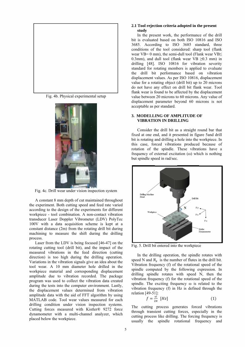
Fig. 4
A conthe experaccordingworkpiectransduce100V wiconstant machininprocess. Laser rotating cmeasureddirection)Variationtool weaworkpiecamplitudeprogram during ththe displamplitudeMATLABdrilling Cutting dynamomplaced be
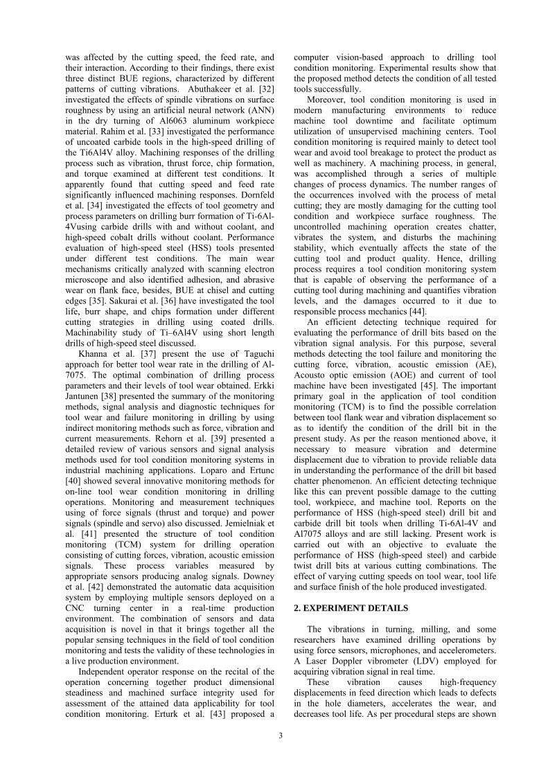
Fig. 4b. Phys
4c. Drill wear u
nstant 8 mm driment. Both cg to the designce - tool comber Laser Dopith a data adistance (2m)
ng to measur
from the LDVcutting tool (d vibrations ) is too high
ns in the vibratar. A 10 mmce material ae due to viwas used to
he tests into thlacement vale data with thB code. Toolcondition unforces measu
meter with aelow the work
sical experime
under vision i
depth of cut macutting speed n of the expebination. A npler Vibrome
acquisition sc) from the rotre the shift
V is being foc(drill bit), andin the feed
h during thetion signals gim diameter and correspoibration recocollect the vihe computer elues determinhe aid of FFTl wear valuesnder vision ured with Ka multi-channkpiece.
ental setup
inspection sys
aintained throand feed rateriments for di
non-contact vieter (LDV) Pcheme is keptating drill bit during the d
cused [46-47]d the impact
d direction (e drilling opeive an idea abhole drilled nding displarded. The pibration data environment. ned from vi
T algorithm bys measured foinspection sy
Kistler® 9272nel analyzer,
5
stem
oughout e varied ifferent ibration PolyTec pt at a
during drilling
] on the of the
(cutting eration. bout the
in the acement package created Lastly,
ibration y using or each ystems. 2 force
which
2
b3cw0dsthdvdfvda
3
fbthrfrb
F
sVsdvsvr
Tthcu
2.1 Tool rejecstudy In the pres
bit is evaluate3685. Accordconditions of wear VB= 0 m0.3mm), and ddrilling [48]. tandard for rhe drill bit
displacement vvalue for a rotdo not have aflank wear is fvalue betweendisplacement acceptable as p
3. MODELLIVIBRATI
Consider thfixed at one enbit is rotating ahis case, forotation of th
frequency of ebut spindle spe
Fig. 5. Drill bi
In the drilpeed N and
Vibration freqpindle compu
drilling spindvibration frequpindle. The
vibration frequelation [49-51
The cutting hrough trans
cutting procesusually the
ction criteria
sent work, thed based on ding to ISOthe tool con
mm), the semi-dull tool (flan
ISO 10816otating membt performanvalues. As pertating object (any effect on found to be af
n 20 microns toparameter be
per standard.
ING OF AMON IN DRIL
he drill bit asnd, and it preand drilling a rced vibratiohe spindle. external excitaeed in rad/sec
t entered into
ling operation is the numb
quency (f) of uted by the
dle rotates wuency (f) for exciting frequuency (f) in H1]:
process genient cutting s like drilling
spindle ro
adopted in th
e performancboth ISO 10
O 3685 stansidered: shar-dull tool (Flank wear VB 6 for vibratbers is applie
nce based or ISO 10816, (drill bit) up tdrill bit flan
ffected by the o 60 microns.eyond 60 mi
MPLITUDE OLLING
s a straight roesented in figuhole into the w
ons producedThese vibratation (ω) whi.
the workpiec
n, the spindleber of flutes inthe rotationalfollowing ex
with speed Nthe rotationaluency ω is rHz is defined
nerates forceforces, espec
g. The forcingotational fre
he present
ce of the drill816 and ISO
andard, threerp tool (flankank wear VB≤≥0.3 mm) intion severity
ed to evaluateon vibrationdisplacement
to 20 micronsnk wear. Tool
displacement Any value oficrons is not
OF
ound bar thature 5and drillworkpiece. In
d because oftions have aich is nothing
e
e rotates withn the drill bit.l speed of thexpression. InN, then thel speed of therelated to thed through the
1
ed vibrationscially in the
g frequency isquency and
l O e k ≤ n y e n t s l t f t
t l n f a g
h . e n e e e e
s e s d

6
harmonics, or the tooth impact frequency and harmonics. In drilling, the frequency of the forced vibration equals the product of the tool/spindle rotational frequency and the number of teeth on the tool (or tooth passing frequency, ). It also called as the fundamental forcing frequency (FFF), and easily changed by adjusting the spindle rpm or some teeth on the tool. Tooth passing frequency of the drill bit computed by following relation [52] where l is the length of the drill bit. Tooth-passing frequency is a critical operational frequency and this defined as the inverse of the time between two subsequent tooth-passes. For a multi-tooth cutter with z teeth and uniform angular spacing between the individual cutting inserts, the tooth passing frequency ) is defined as:
∗ (2)
In drilling, an amplitude of forced vibrations depends on the magnitude of the exciting force and on the dynamic stiffness of the machine tool, cutting tool, and the workpiece, which are often an order of an amount lower than the static values. Frequency response function (FRF) will exhibit compliance or flexibility of the part at every frequency. For a linear system the displacement of the part at each frequency can be determined from the FFF and FRF [53]:
Displacement, Q (µm) = FFF (N) x FRF (µm/N) (3)
Present work mainly focused on the transverse vibrations. It is due to the transverse vibrations produced during the drilling operation are the primary cause of the enlargement of the diameter of the hole produced beyond tolerance limit. It is important to note that a large part of the energy dissipation occurs at the tool holder–spindle interface. It is often convenient to characterize a linear system by its response to a specific sinusoidal input force given by . 4 Where F is the forcing amplitude is the time is the exciting frequency in rad/sec
A modal Fourier transform analysis is performed using for the displacement . Where the forcing function is and ω is the Fourier transform of . The steady-state response of this system, which is present as long as the forcing function is active, is given by: . 5
6
, the frequency response function (FRF) of the system is the ratio of the complex amplitude of the displacement (which is a harmonic motion with frequency ω) to the magnitude For the forcing function. The amplitude of vibration produced by a unit force at the frequency 'ω.' In the present work, both forces applied by the machine on the tool and resistive force applied by the workpiece during the drilling operation considered. When drill touches the workpiece and starts cutting the material to produce the hole, the upward resistive force acts on the drill because of the tensile stress of the workpiece
material. When the material breaks during drilling the hole, its failure in the longitudinal direction considered as the compressive failure. The amplitude (Q) of the forced vibration computed with no damping condition using the formula given below [51]:
2. ..
1 7
Where f= frequency of vibration, f= tooth passing frequency, A = amplitude of excitation, G -shear modulus, a - acceleration of drill and r - radius of the drill. The maximum displacement amplitude will found at the 1st harmonic of the forcing frequency. Displacement amplitude maximum because the dynamic flexibility is near the resonant frequency. To characterize the ability to resist this kind of vibration, an index of machine tool dynamic stiffness (k) is used [53]:
8
4. VIBRATION SIGNAL PROCESSING USING
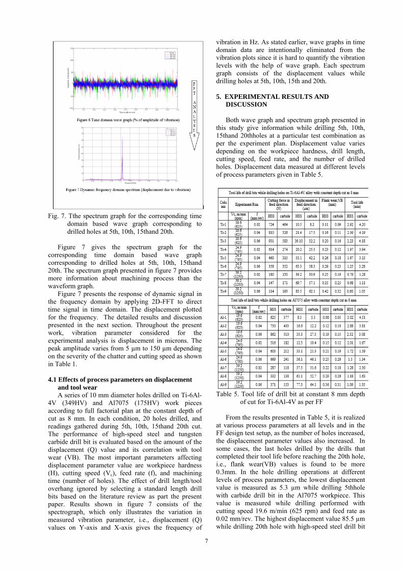
FAST FOURIER TRANSFORM The actual implantation of the real-time monitoring system typically starts with designing a proof-of-concept experiment. Acousto optic emission (AOE) based tool wear identification is primarily subject to the interpretation of the captured signals. However, the extraction of essential features useful for tool wears identification from the collected acousto optic emission signal. In this work, time-series analysis applied to the wave signals for detecting percent of the amplitude of displacement due to vibration during drilling. All the time domain signals in the present work are filtered using a 0-500Hz band pass filter, and signal processing involved signal blocks of 3200 data points collected over a sampling interval 500 milliseconds. In the present work, vibration raw signals are gathered using an LDV, and the vibration amplitude plotted against time domain. This form of representation is called waveform graph, and it showed in figure 6 which consists of time domain data while drilling holes at 5th, 10th, 15th and 20th.Wave graphs give the percentage of vibration amplitude only for a particular time domain data. Hence, it is tough or often impossible to quantify the vibration levels with the help of wave graph. Moreover, direct time-series analysis is usually incapable of isolating defect-scattered information appropriately from noise in different frequency bands. Therefore, time domain signal must convert into converted to frequency domain as spectrum graphs by using a fast Fourier transform (FFT). Fast Fourier transform is utilized to determine the vibration parameter, i.e., displacement (microns) in the frequency domain for analysis of the vibration signal.
7
Fig. 7. Tthe spectrum graph for the corresponding time
domain based wave graph corresponding to drilled holes at 5th, 10th, 15thand 20th.
Figure 7 gives the spectrum graph for the corresponding time domain based wave graph corresponding to drilled holes at 5th, 10th, 15thand 20th. The spectrum graph presented in figure 7 provides more information about machining process than the waveform graph. Figure 7 presents the response of dynamic signal in the frequency domain by applying 2D-FFT to direct time signal in time domain. The displacement plotted for the frequency. The detailed results and discussion presented in the next section. Throughout the present work, vibration parameter considered for the experimental analysis is displacement in microns. The peak amplitude varies from 5 µm to 150 µm depending on the severity of the chatter and cutting speed as shown in Table 1. 4.1 Effects of process parameters on displacement
and tool wear A series of 10 mm diameter holes drilled on Ti-6Al-4V (349HV) and Al7075 (175HV) work pieces according to full factorial plan at the constant depth of cut as 8 mm. In each condition, 20 holes drilled, and readings gathered during 5th, 10th, 15thand 20th cut. The performance of high-speed steel and tungsten carbide drill bit is evaluated based on the amount of the displacement (Q) value and its correlation with tool wear (VB). The most important parameters affecting displacement parameter value are workpiece hardness (H), cutting speed (Vc), feed rate (f), and machining time (number of holes). The effect of drill length/tool overhang ignored by selecting a standard length drill bits based on the literature review as part the present paper. Results shown in figure 7 consists of the spectrograph, which only illustrates the variation in measured vibration parameter, i.e., displacement (Q) values on Y-axis and X-axis gives the frequency of
vibration in Hz. As stated earlier, wave graphs in time domain data are intentionally eliminated from the vibration plots since it is hard to quantify the vibration levels with the help of wave graph. Each spectrum graph consists of the displacement values while drilling holes at 5th, 10th, 15th and 20th. 5. EXPERIMENTAL RESULTS AND
DISCUSSION Both wave graph and spectrum graph presented in this study give information while drilling 5th, 10th, 15thand 20thholes at a particular test combination as per the experiment plan. Displacement value varies depending on the workpiece hardness, drill length, cutting speed, feed rate, and the number of drilled holes. Displacement data measured at different levels of process parameters given in Table 5.
Table 5. Tool life of drill bit at constant 8 mm depth
of cut for Ti-6Al-4V as per FF From the results presented in Table 5, it is realized at various process parameters at all levels and in the FF design test setup, as the number of holes increased, the displacement parameter values also increased. In some cases, the last holes drilled by the drills that completed their tool life before reaching the 20th hole, i.e., flank wear(VB) values is found to be more 0.3mm. In the hole drilling operations at different levels of process parameters, the lowest displacement value is measured as 5.3 µm while drilling 5thhole with carbide drill bit in the Al7075 workpiece. This value is measured while drilling performed with cutting speed 19.6 m/min (625 rpm) and feed rate as 0.02 mm/rev. The highest displacement value 85.5 µm while drilling 20th hole with high-speed steel drill bit
8
in the Ti-6Al-4V workpiece. This value found while drilling performed, with cutting speed 39.2 m/min (1250 rpm) and feed rate as 0.06 mm/rev. It understood from Table 5 that the selection of a lower cutting speed and higher feed rate would have been more appropriate. Results in Table 5, it indicates that the cutting speed contributed to 51% of the variation of drilling vibrations, followed by the feed rate, which results in 35.3% of the total variation. The present study on the drilling of Ti-6Al-4V and Al7075 alloys using high-speed steel and tungsten carbide twist drills demonstrated an increase of displacement value at feed rate 0.02 mm/rev, 0.04 mm/rev and 0.06 mm/rev. 5.1 Main effects of process parameters on
displacement amplitude and tool wear Main effect graphics show the types of effects of dependent variables (output parameters) at different levels of independent variables (input parameters) [54]. In the drilling of Ti-6Al-4V and Al7075 specimens with high-speed steel and tungsten carbide twist drills having same lengths, the main effects of the process parameters on displacement amplitude (Q) shown in figure 8.
Fig. 8. Main effects of the process parameters on
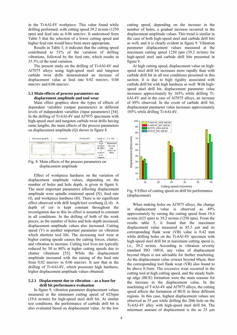
displacement amplitude Effect of workpiece hardness on the variation of displacement amplitude values, depending on the number of holes and hole depth, is given in figure 8. The most important parameters affecting displacement amplitude were spindle rotational speed (N), feed rate (f), and workpiece hardness (H). There is no significant effect observed with drill length/tool overhang (L/d). A depth of cut is kept constant throughout the investigation due to this its effect is assumed to constant in all conditions. In the drilling of both of the work pieces, as the number of holes and hole depth increased, displacement amplitude values also increased. Cutting speed (V) is another important parameter on vibration which shortens tool life. The increasing tool wear at higher cutting speeds causes the cutting forces, chatter, and vibration to increase. Cutting tool lives are typically reduced by 50 to 80% at higher cutting speeds due to chatter vibrations [55]. While the displacement amplitude increased with the raising of the feed rate from 0.02 mm/rev to 0.06 mm/rev. It saw that in the drilling of Ti-6Al-4V, which possesses high hardness, higher displacement amplitude values obtained. 5.2.1 Displacement due to vibration – as a base for
drill bit performance evaluation In figure 9, vibration parameter displacement values
measured at the minimum cutting speed of 625rpm (19.6 m/min) for high-speed steel drill bit. At similar test conditions, the performance of carbide drill bit is also evaluated based on displacement value. At the low
cutting speed, depending on the increase in the number of holes, a gradual increase occurred in the displacement amplitude values. This trend is similar in the case of both high-speed steel and carbide drill bits as well, and it is clearly evident in figure 9. Vibration parameter displacement values measured at the maximum cutting speed 1250 rpm (39.2 m/min) for high-speed steel and carbide drill bits presented in figure 9.
At high cutting speed, displacement value on high-speed steel drill bit increases more rapidly than with carbide drill bit in all test conditions presented in this section. It is due to high rigidity associated with carbide drill bit with high hardness as well. With high-speed steel drill bit, displacement parameter value increases approximately by 165% while drilling Ti-6Al-4V and in the case of Al7075 alloys, an increase of 89% observed. In the event of carbide drill bit, displacement parameter value increases approximately 105% while drilling Ti-6Al-4V.
15 20 25 30 35 400
10
20
30
40
50
60
70
80
90
100
Dis
plac
emen
t,Q(m
icro
ns)
Cutting speed,Vc(m/min)
Ti-6Al-4V_HSS drill bit Ti-6Al-4V_WC drill bit Al7075_HSS drill bit Al7075_WC drill bit
Fig. 9 Effect of cutting speed on drill bit performance (displacement) When making holes on Al7075 alloys, the change in displacement value is observed as 49% approximately by raising the cutting speed from 19.6 m/min (625 rpm) to 39.2 m/min (1250 rpm). From the results table 5, it found that the maximum displacement value measured as 85.5 µm and its corresponding flank wear (VB) value is 0.42 mm while drilling holes on the Ti-6Al-4V specimen with high-speed steel drill bit at maximum cutting speed is, i.e., 39.2 m/min. According to vibration severity standard ISO 10816, any value of displacement beyond 60µm is not advisable for further machining. As the displacement value crosses beyond 60µm, then the corresponding tool flank wear (VB) also found to be above 0.3mm. The excessive wear occurred in the cutting tool at high cutting speed, and the steady built-up edge (BUE) formation were the main reasons for the increase in the displacement value. In the machining of T-6Al-4V and Al7075 alloys, the cutting speed affects the formation of BUE in three different regions. In this case, highest displacement values are observed as 55 µm while drilling the 20th hole on the Ti-6Al-4V alloy with high-speed steel drill bit. The minimum amount of displacement is the as 25 µm
9
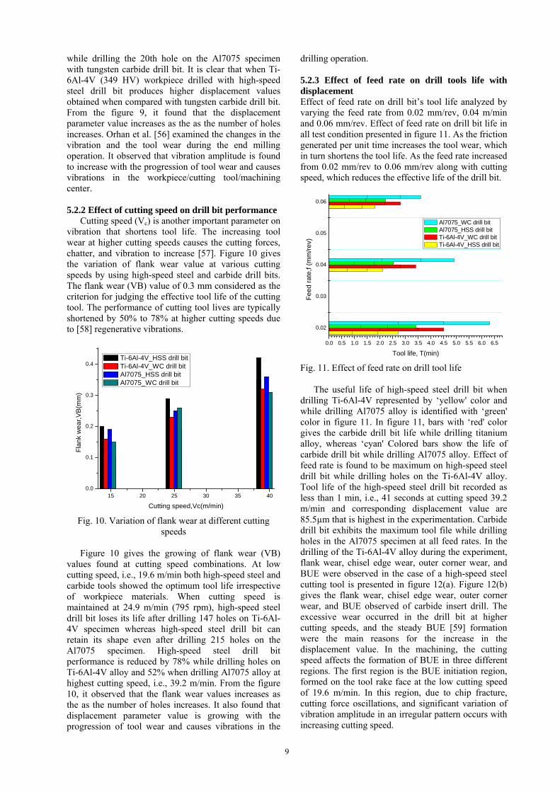
while drilling the 20th hole on the Al7075 specimen with tungsten carbide drill bit. It is clear that when Ti-6Al-4V (349 HV) workpiece drilled with high-speed steel drill bit produces higher displacement values obtained when compared with tungsten carbide drill bit. From the figure 9, it found that the displacement parameter value increases as the as the number of holes increases. Orhan et al. [56] examined the changes in the vibration and the tool wear during the end milling operation. It observed that vibration amplitude is found to increase with the progression of tool wear and causes vibrations in the workpiece/cutting tool/machining center. 5.2.2 Effect of cutting speed on drill bit performance Cutting speed (Vc) is another important parameter on vibration that shortens tool life. The increasing tool wear at higher cutting speeds causes the cutting forces, chatter, and vibration to increase [57]. Figure 10 gives the variation of flank wear value at various cutting speeds by using high-speed steel and carbide drill bits. The flank wear (VB) value of 0.3 mm considered as the criterion for judging the effective tool life of the cutting tool. The performance of cutting tool lives are typically shortened by 50% to 78% at higher cutting speeds due to [58] regenerative vibrations.
15 20 25 30 35 400.0
0.1
0.2
0.3
0.4 Ti-6Al-4V_HSS drill bit Ti-6Al-4V_WC drill bit Al7075_HSS drill bit Al7075_WC drill bit
Fla
nk
wea
r,V
B(m
m)
Cutting speed,Vc(m/min)
Fig. 10. Variation of flank wear at different cutting speeds
Figure 10 gives the growing of flank wear (VB) values found at cutting speed combinations. At low cutting speed, i.e., 19.6 m/min both high-speed steel and carbide tools showed the optimum tool life irrespective of workpiece materials. When cutting speed is maintained at 24.9 m/min (795 rpm), high-speed steel drill bit loses its life after drilling 147 holes on Ti-6Al-4V specimen whereas high-speed steel drill bit can retain its shape even after drilling 215 holes on the Al7075 specimen. High-speed steel drill bit performance is reduced by 78% while drilling holes on Ti-6Al-4V alloy and 52% when drilling Al7075 alloy at highest cutting speed, i.e., 39.2 m/min. From the figure 10, it observed that the flank wear values increases as the as the number of holes increases. It also found that displacement parameter value is growing with the progression of tool wear and causes vibrations in the
drilling operation. 5.2.3 Effect of feed rate on drill tools life with displacement Effect of feed rate on drill bit’s tool life analyzed by varying the feed rate from 0.02 mm/rev, 0.04 m/min and 0.06 mm/rev. Effect of feed rate on drill bit life in all test condition presented in figure 11. As the friction generated per unit time increases the tool wear, which in turn shortens the tool life. As the feed rate increased from 0.02 mm/rev to 0.06 mm/rev along with cutting speed, which reduces the effective life of the drill bit.
0.02
0.03
0.04
0.05
0.06
0.0 0.5 1.0 1.5 2.0 2.5 3.0 3.5 4.0 4.5 5.0 5.5 6.0 6.5
Tool life, T(min)
Fee
d ra
te,f
(mm
/re
v)
Al7075_WC drill bit Al7075_HSS drill bit Ti-6Al-4V_WC drill bit Ti-6Al-4V_HSS drill bit
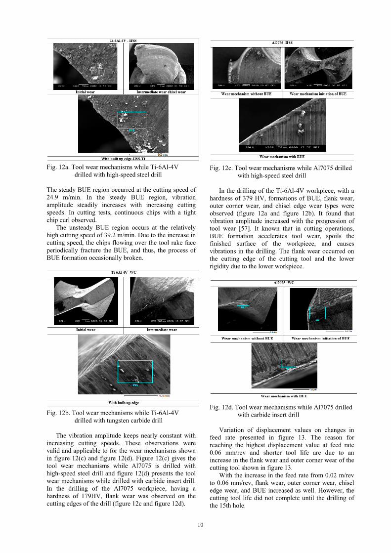
Fig. 11. Effect of feed rate on drill tool life The useful life of high-speed steel drill bit when drilling Ti-6Al-4V represented by ‘yellow' color and while drilling Al7075 alloy is identified with ‘green' color in figure 11. In figure 11, bars with ‘red' color gives the carbide drill bit life while drilling titanium alloy, whereas ‘cyan' Colored bars show the life of carbide drill bit while drilling Al7075 alloy. Effect of feed rate is found to be maximum on high-speed steel drill bit while drilling holes on the Ti-6Al-4V alloy. Tool life of the high-speed steel drill bit recorded as less than 1 min, i.e., 41 seconds at cutting speed 39.2 m/min and corresponding displacement value are 85.5µm that is highest in the experimentation. Carbide drill bit exhibits the maximum tool file while drilling holes in the Al7075 specimen at all feed rates. In the drilling of the Ti-6Al-4V alloy during the experiment, flank wear, chisel edge wear, outer corner wear, and BUE were observed in the case of a high-speed steel cutting tool is presented in figure 12(a). Figure 12(b) gives the flank wear, chisel edge wear, outer corner wear, and BUE observed of carbide insert drill. The excessive wear occurred in the drill bit at higher cutting speeds, and the steady BUE [59] formation were the main reasons for the increase in the displacement value. In the machining, the cutting speed affects the formation of BUE in three different regions. The first region is the BUE initiation region, formed on the tool rake face at the low cutting speed of 19.6 m/min. In this region, due to chip fracture, cutting force oscillations, and significant variation of vibration amplitude in an irregular pattern occurs with increasing cutting speed.
10
Fig. 12a. Tool wear mechanisms while Ti-6Al-4V
drilled with high-speed steel drill The steady BUE region occurred at the cutting speed of 24.9 m/min. In the steady BUE region, vibration amplitude steadily increases with increasing cutting speeds. In cutting tests, continuous chips with a tight chip curl observed. The unsteady BUE region occurs at the relatively high cutting speed of 39.2 m/min. Due to the increase in cutting speed, the chips flowing over the tool rake face periodically fracture the BUE, and thus, the process of BUE formation occasionally broken.
Fig. 12b. Tool wear mechanisms while Ti-6Al-4V
drilled with tungsten carbide drill The vibration amplitude keeps nearly constant with increasing cutting speeds. These observations were valid and applicable to for the wear mechanisms shown in figure 12(c) and figure 12(d). Figure 12(c) gives the tool wear mechanisms while Al7075 is drilled with high-speed steel drill and figure 12(d) presents the tool wear mechanisms while drilled with carbide insert drill. In the drilling of the Al7075 workpiece, having a hardness of 179HV, flank wear was observed on the cutting edges of the drill (figure 12c and figure 12d).
Fig. 12c. Tool wear mechanisms while Al7075 drilled
with high-speed steel drill
In the drilling of the Ti-6Al-4V workpiece, with a hardness of 379 HV, formations of BUE, flank wear, outer corner wear, and chisel edge wear types were observed (figure 12a and figure 12b). It found that vibration amplitude increased with the progression of tool wear [57]. It known that in cutting operations, BUE formation accelerates tool wear, spoils the finished surface of the workpiece, and causes vibrations in the drilling. The flank wear occurred on the cutting edge of the cutting tool and the lower rigidity due to the lower workpiece.
Fig. 12d. Tool wear mechanisms while Al7075 drilled
with carbide insert drill Variation of displacement values on changes in feed rate presented in figure 13. The reason for reaching the highest displacement value at feed rate 0.06 mm/rev and shorter tool life are due to an increase in the flank wear and outer corner wear of the cutting tool shown in figure 13. With the increase in the feed rate from 0.02 m/rev to 0.06 mm/rev, flank wear, outer corner wear, chisel edge wear, and BUE increased as well. However, the cutting tool life did not complete until the drilling of the 15th hole.
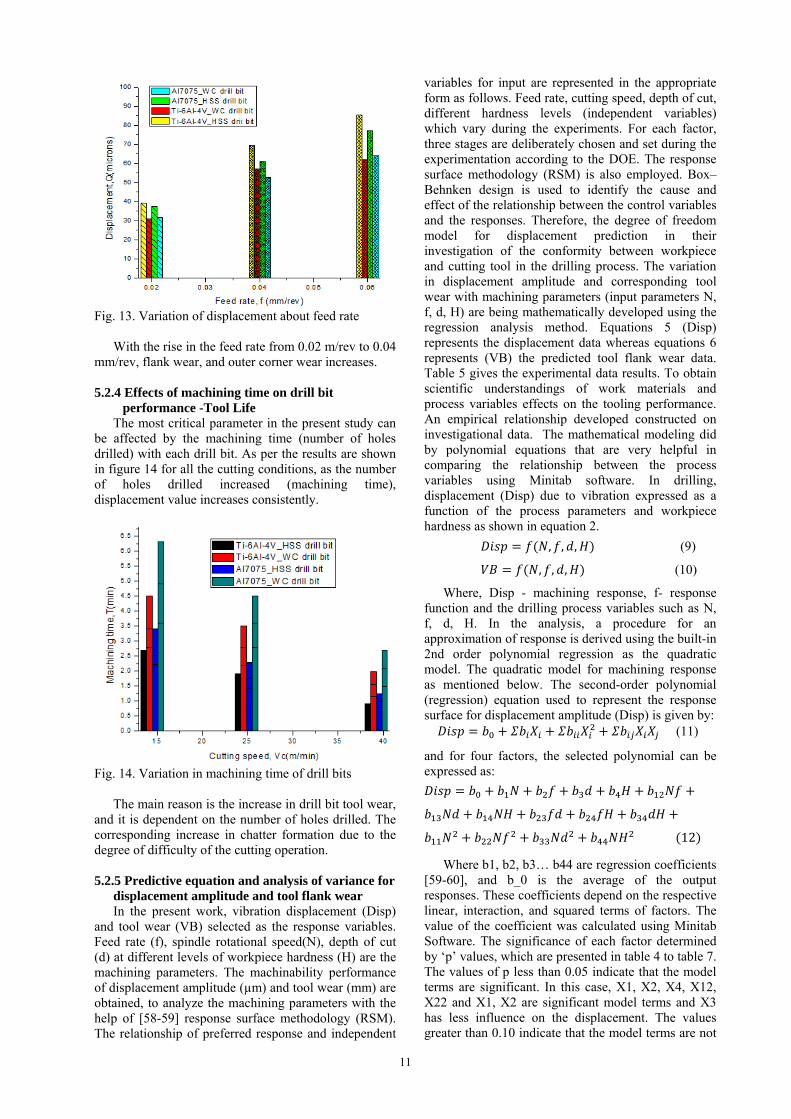
11
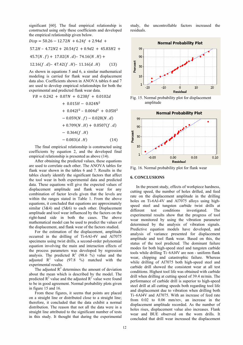
Fig. 13. Variation of displacement about feed rate With the rise in the feed rate from 0.02 m/rev to 0.04 mm/rev, flank wear, and outer corner wear increases. 5.2.4 Effects of machining time on drill bit
performance -Tool Life The most critical parameter in the present study can be affected by the machining time (number of holes drilled) with each drill bit. As per the results are shown in figure 14 for all the cutting conditions, as the number of holes drilled increased (machining time), displacement value increases consistently.
Fig. 14. Variation in machining time of drill bits The main reason is the increase in drill bit tool wear, and it is dependent on the number of holes drilled. The corresponding increase in chatter formation due to the degree of difficulty of the cutting operation. 5.2.5 Predictive equation and analysis of variance for
displacement amplitude and tool flank wear In the present work, vibration displacement (Disp) and tool wear (VB) selected as the response variables. Feed rate (f), spindle rotational speed(N), depth of cut (d) at different levels of workpiece hardness (H) are the machining parameters. The machinability performance of displacement amplitude (µm) and tool wear (mm) are obtained, to analyze the machining parameters with the help of [58-59] response surface methodology (RSM). The relationship of preferred response and independent
variables for input are represented in the appropriate form as follows. Feed rate, cutting speed, depth of cut, different hardness levels (independent variables) which vary during the experiments. For each factor, three stages are deliberately chosen and set during the experimentation according to the DOE. The response surface methodology (RSM) is also employed. Box–Behnken design is used to identify the cause and effect of the relationship between the control variables and the responses. Therefore, the degree of freedom model for displacement prediction in their investigation of the conformity between workpiece and cutting tool in the drilling process. The variation in displacement amplitude and corresponding tool wear with machining parameters (input parameters N, f, d, H) are being mathematically developed using the regression analysis method. Equations 5 (Disp) represents the displacement data whereas equations 6 represents (VB) the predicted tool flank wear data. Table 5 gives the experimental data results. To obtain scientific understandings of work materials and process variables effects on the tooling performance. An empirical relationship developed constructed on investigational data. The mathematical modeling did by polynomial equations that are very helpful in comparing the relationship between the process variables using Minitab software. In drilling, displacement (Disp) due to vibration expressed as a function of the process parameters and workpiece hardness as shown in equation 2.
, , , (9)
, , , (10)
Where, Disp - machining response, f- response function and the drilling process variables such as N, f, d, H. In the analysis, a procedure for an approximation of response is derived using the built-in 2nd order polynomial regression as the quadratic model. The quadratic model for machining response as mentioned below. The second-order polynomial (regression) equation used to represent the response surface for displacement amplitude (Disp) is given by: (11)
and for four factors, the selected polynomial can be expressed as:
12
Where b1, b2, b3… b44 are regression coefficients [59-60], and b_0 is the average of the output responses. These coefficients depend on the respective linear, interaction, and squared terms of factors. The value of the coefficient was calculated using Minitab Software. The significance of each factor determined by ‘p’ values, which are presented in table 4 to table 7. The values of p less than 0.05 indicate that the model terms are significant. In this case, X1, X2, X4, X12, X22 and X1, X2 are significant model terms and X3 has less influence on the displacement. The values greater than 0.10 indicate that the model terms are not
12
significant [60]. The final empirical relationship is constructed using only these coefficients and developed the empirical relationship given below.
50.26 12.72 6.24 2.94
57.2 – 4.72 2 20.54 2 0.9 2 45.83 2
45.7 . 17.02 . – 74.16 .
12.16 . – 47.42 . – 11.16 . 13
As shown in equations 5 and 6, a similar mathematical modeling is carried for flank wear and displacement data also. Coefficients shown in ANOVA tables 6 and 7 are used to develop empirical relationships for both the experimental and predicted flank wear data.
0.242 0.07 0.238 0.0102
0.015 0.024N
0.042f – 0.004d 0.05H
0.059 . 0.028 .
0.709 . 0.0507 .
0.364 .
0.083 . 14
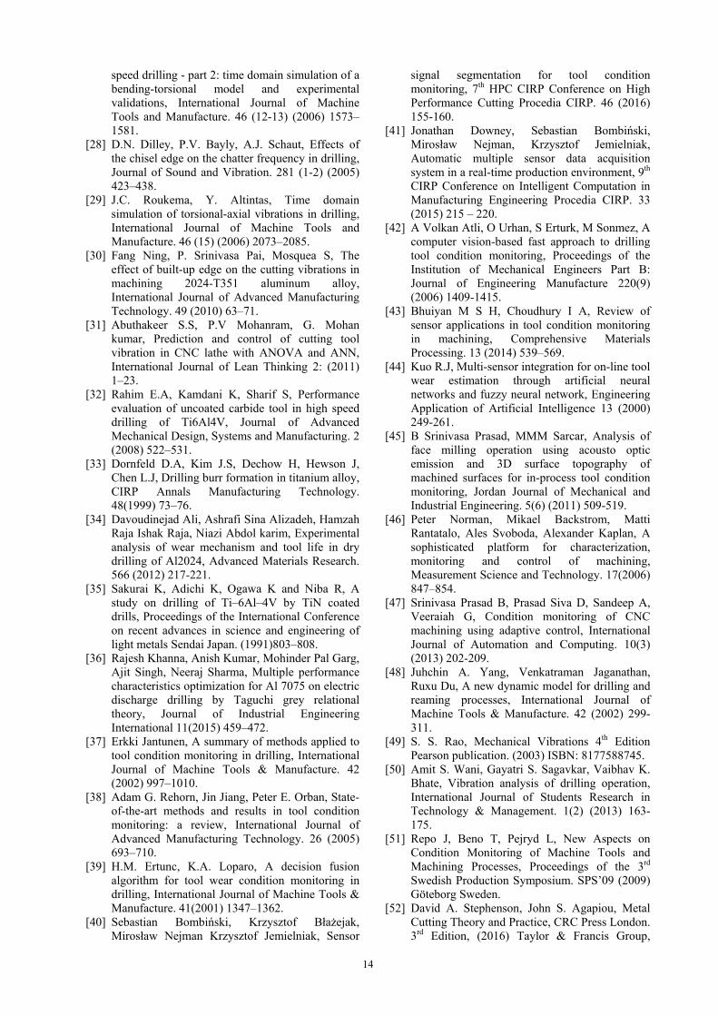
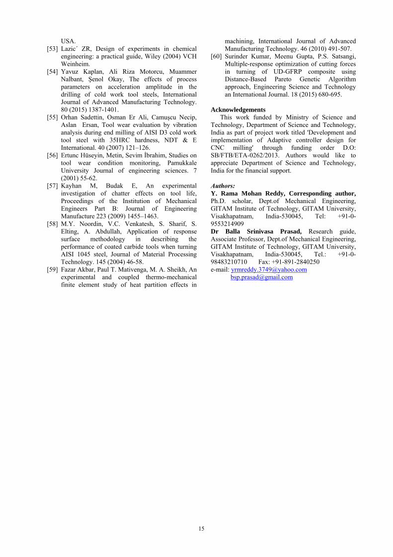
The final empirical relationship is constructed using coefficients by equation 2, and the developed final empirical relationship is presented as above (14). After obtaining the predicted values, these equations are used to correlate each other. The ANOVA tables for flank wear shown in the tables 6 and 7. Results in the tables clearly identify the significant factors that affect the tool wear in both experimental data and predicted data. These equations will give the expected values of displacement amplitude and flank wear for any combination of factor levels given that the levels are within the ranges stated in Table 1. From the above equations, it concluded that equations are approximately similar (3&4) and (5&6) to each other. Displacement amplitude and tool wear influenced by the factors on the right-hand side in both the cases. The above mathematical model can be used to predict the values of the displacement, and flank wear of the factors studied. For the estimation of the displacement, amplitude occurred in the drilling of Ti-6Al-4V and Al7075 specimens using twist drills, a second-order polynomial equation involving the main and interaction effects of the process parameters was developed by regression analysis. The predicted R2 (98.6 %) value and the adjusted R2 value (97.8 %) matched with the experimental results. The adjusted R2 determines the amount of deviation about the mean which is described by the model. The predicted R2 value and the adjusted R2 value were found to be in good agreement. Normal probability plots given in figure 15 and 16. From these figures, it seems that points are placed on a straight line or distributed close to a straight line; therefore, it concluded that the data exhibit a normal distribution. The reason that not all the data were in a straight line attributed to the significant number of tests in this study. It thought that during the experimental
study, the uncontrollable factors increased the residuals.
Fig. 15. Normal probability plot for displacement
amplitude
Fig. 16. Normal probability plot for flank wear 6. CONCLUSIONS In the present study, effects of workpiece hardness, cutting speed, the number of holes drilled, and feed rate on the displacement amplitude in the drilling holes on Ti-6Al-4V and Al7075 alloys using high-speed steel and tungsten carbide twist drills at different test conditions investigated. The experimental results show that the progress of tool wear monitored by using the vibration parameter determined by the analysis of vibration signals. Predictive equation models have developed, and analysis of variance presented for displacement amplitude and tool flank wear. Based on this, the status of the tool predicted. The dominant failure modes for both high-speed steel and tungsten carbide tools while drilling Ti–6Al4V are non - uniform flank wear, chipping and catastrophic failure. Whereas while drilling of Al7075 both high-speed steel and carbide drill showed the consistent wear at all test conditions. Highest tool life was obtained with carbide drill when drilling at cutting speed of 39.4 m/min. The performance of carbide drill is superior to high-speed steel drill at all cutting speeds both regarding tool life and displacement due to vibration when drilling both Ti–6Al4V and Al7075. With an increase of feed rate from 0.02 to 0.06 mm/rev, an increase in the displacement amplitude recorded. As the number of holes rises, displacement value also increases. Flank wear and BUE observed on the worn drills. It concluded that drill wear increased the displacement

13
amplitude values. The vibration signals are measured which indirectly track tool wear. These signals are affected by the cutting conditions, workpiece material, and type of tool. For example, increasing the feed rate during the drilling process leads to a proportional rise in the measured signals. This situation could be confused with increased displacement due to tool wear in the system. Finally, the methods proposed in this paper can also be used for performance evaluation of drill tools effectively by monitoring vibration induced drilling. 7. REFERENCES [1] Leyens Christoph and Peters Manfred, Titanium
and Titanium Alloys Fundamentals and Applications WILEY-VCH Verlag GmbH& Co, 2005, Germany.
[2] Brewer William D, Bird R.Keith and Wallace Terryl A, Titanium alloys and processing for high speed aircraft, Materials Science and Engineering A. 243(1998) 299–304.
[3] Kandilli Ismet, Sönmez Murat, Ertunc Huseyin Metin, Çakır Bekir, Online monitoring of tool wear in drilling and milling by multi-sensor neural network fusion, Proceedings of the IEEE International Conference on Mechatronics and Automation. China. (2007) 1388-1394.
[4] W. Grzesik, An Investigation of the Thermal Effects in Orthogonal Cutting Associated with Multilayer Coatings, Annals of the CIRP. 50 (2001) 53-56.
[5] S. Dolinšek, J. Kopač, Mechanism and types of tool wear; particularities in advanced cutting Materials, Journal of Achievements in Materials and Manufacturing Engineering. 19(1) (2006) 11-18.
[6] Sikiru Oluwarotimi Ismail, HomNath Dhakal, Eric Dimla, Ivan Popov, Recent advances in twist drill design for composite machining: A critical review, Proceedings of the institution of mechanical engineers Part B Journal of Engineering Manufacture. (2016) 1–16. doi: 10.1177/0954405416635034.
[7] Brinksmeier E, Prediction of Tool Fracture in Drilling, Annals of CIRP. 39(1) (1990) 97-100.
[8] Kanai M, Fujii S, Kanda Y, Statistical Characteristics of Drill Wear and Drill Life for the Standardized Performance Tests, Annals of CIRP. 27(1) (1978) 61-66.
[9] Kaldor S, Lenz E, Investigation in Tool Life of Twist Drill, Annals of CIRP. 52 (1980) 30-35.
[10] Choudhury S. K, Raju G, Investigation into Crater Wear in Drilling, International Journal of Machine Tools & Manufacture. 40 (2000) 887-898.
[11] Harris S G, Doyle E D, Vlasveld A C, Audy J, Quick D, A Study of the Wear Mechanism of Ti1-xAlx N and Ti1-x-yAlx CryN Coated High Speed Steel Twist Drill Under Dry Machining Conditions, Wear. 254 (2003) 723-734.
[12] Tetsutaro H, Zhao H, Study of a High Performance Drill, Geometry Annals of CIRP. 38: (1989) 87-90.
[13] S.C. Lin, C.J. Ting, Tool wear monitoring in
drilling using force signals, Wear. 180(1) (1995) 53-60.
[14] Muhammad Imran, Paul T Mativenga, Ali Gholinia, Philip J Withers, Comparison of tool wear mechanisms and surface integrity for dry and wet micro-drilling of nickel-base super alloys, International Journal of Machine Tools & Manufacture. 76 (2014) 49–60.
[15] H.S. Liu, B.Y. Lee, Y.S. Tarng, In-process prediction of corner wear in drilling operations, Journal of Materials Processing Technology. 101: (2000) 152-158.
[16] T.I. El Wardany, Gao D, Elbestawi M A, Tool condition monitoring in drilling using vibration signature analysis, International Journal of Machine Tools and Manufacture. 36(6) (1996) 687-711.
[17] Abuthakeer S.S, P.V Mohanram, G. Mohankumar, The effect of spindle vibration on surface roughness of workpiece in dry turning using ANN International, Journal of Lean Thinking. 2 (2011) 42–58.
[18] Izelu C.O, Eze S.C, Oreko B.U, Edward B.A, Garba D.K, Response surface methodology in the study of induced machining vibration and work surface roughness in the turning of 41Cr4 alloy steel, International Journal of Emerging Technology and Advanced Engineering. 3 (2013) 13–17.
[19] Khalili K and Danesh M, Investigation of overhang effect on cutting tool vibration for tool condition monitoring, Journal of Measurements in Engineering 1(2013) 171–177.
[20] Guillem Quintana, Joaquim Ciurana, Chatter in machining processes: A review, International Journal of Machine Tools & Manufacture. 51(2011) 363–376.
[21] S.A. Tobias, Machine tool vibration research, International Journal of Machine Tool Design Research. 1 (1961) 1-14.
[22] N.H. Hanna, S.A. Tobias, Theory of nonlinear regenerative chatter, Journal of Engineering for Industry Transactions of the ASME. 96 Ser B(1) (1974) 247–255.
[23] S. Ema, E. Marui, Theoretical analysis on chatter vibration in drilling and its suppression, Journal of Materials Processing Technology. 138 (1-3) (2003) 572–578.
[24] S. Ema, H. Fujii, E. Marui, Chatter Vibration in Drilling, Transactions of the ASME Journal of Engineering for Industry. 110 (1988) 309-314.
[25] Iman Maleki Mehrabadi, Mohammad Nouri, Reza Madoliat, Investigating chatter vibration in deep drilling, including process damping and the gyroscopic effect, International Journal of Machine Tools & Manufacture. 49 (2009) 939–946.
[26] T. Arvajeh, F. Ismail, Machining stability in high-speed drilling - part 1: modeling vibration stability in bending, International Journal of Machine Tools and Manufacture. 46(12-13) (2006) 1563–157259.
[27] T. Arvajeh, F. Ismail, Machining stability in high
14
speed drilling - part 2: time domain simulation of a bending-torsional model and experimental validations, International Journal of Machine Tools and Manufacture. 46 (12-13) (2006) 1573–1581.
[28] D.N. Dilley, P.V. Bayly, A.J. Schaut, Effects of the chisel edge on the chatter frequency in drilling, Journal of Sound and Vibration. 281 (1-2) (2005) 423–438.
[29] J.C. Roukema, Y. Altintas, Time domain simulation of torsional-axial vibrations in drilling, International Journal of Machine Tools and Manufacture. 46 (15) (2006) 2073–2085.
[30] Fang Ning, P. Srinivasa Pai, Mosquea S, The effect of built-up edge on the cutting vibrations in machining 2024-T351 aluminum alloy, International Journal of Advanced Manufacturing Technology. 49 (2010) 63–71.
[31] Abuthakeer S.S, P.V Mohanram, G. Mohan kumar, Prediction and control of cutting tool vibration in CNC lathe with ANOVA and ANN, International Journal of Lean Thinking 2: (2011) 1–23.
[32] Rahim E.A, Kamdani K, Sharif S, Performance evaluation of uncoated carbide tool in high speed drilling of Ti6Al4V, Journal of Advanced Mechanical Design, Systems and Manufacturing. 2 (2008) 522–531.
[33] Dornfeld D.A, Kim J.S, Dechow H, Hewson J, Chen L.J, Drilling burr formation in titanium alloy, CIRP Annals Manufacturing Technology. 48(1999) 73–76.
[34] Davoudinejad Ali, Ashrafi Sina Alizadeh, Hamzah Raja Ishak Raja, Niazi Abdol karim, Experimental analysis of wear mechanism and tool life in dry drilling of Al2024, Advanced Materials Research. 566 (2012) 217-221.
[35] Sakurai K, Adichi K, Ogawa K and Niba R, A study on drilling of Ti–6Al–4V by TiN coated drills, Proceedings of the International Conference on recent advances in science and engineering of light metals Sendai Japan. (1991)803–808.
[36] Rajesh Khanna, Anish Kumar, Mohinder Pal Garg, Ajit Singh, Neeraj Sharma, Multiple performance characteristics optimization for Al 7075 on electric discharge drilling by Taguchi grey relational theory, Journal of Industrial Engineering International 11(2015) 459–472.
[37] Erkki Jantunen, A summary of methods applied to tool condition monitoring in drilling, International Journal of Machine Tools & Manufacture. 42 (2002) 997–1010.
[38] Adam G. Rehorn, Jin Jiang, Peter E. Orban, State-of-the-art methods and results in tool condition monitoring: a review, International Journal of Advanced Manufacturing Technology. 26 (2005) 693–710.
[39] H.M. Ertunc, K.A. Loparo, A decision fusion algorithm for tool wear condition monitoring in drilling, International Journal of Machine Tools & Manufacture. 41(2001) 1347–1362.
[40] Sebastian Bombiński, Krzysztof Błażejak, Mirosław Nejman Krzysztof Jemielniak, Sensor
signal segmentation for tool condition monitoring, 7th HPC CIRP Conference on High Performance Cutting Procedia CIRP. 46 (2016) 155-160.
[41] Jonathan Downey, Sebastian Bombiński, Mirosław Nejman, Krzysztof Jemielniak, Automatic multiple sensor data acquisition system in a real-time production environment, 9th CIRP Conference on Intelligent Computation in Manufacturing Engineering Procedia CIRP. 33 (2015) 215 – 220.
[42] A Volkan Atli, O Urhan, S Erturk, M Sonmez, A computer vision-based fast approach to drilling tool condition monitoring, Proceedings of the Institution of Mechanical Engineers Part B: Journal of Engineering Manufacture 220(9) (2006) 1409-1415.
[43] Bhuiyan M S H, Choudhury I A, Review of sensor applications in tool condition monitoring in machining, Comprehensive Materials Processing. 13 (2014) 539–569.
[44] Kuo R.J, Multi-sensor integration for on-line tool wear estimation through artificial neural networks and fuzzy neural network, Engineering Application of Artificial Intelligence 13 (2000) 249-261.
[45] B Srinivasa Prasad, MMM Sarcar, Analysis of face milling operation using acousto optic emission and 3D surface topography of machined surfaces for in-process tool condition monitoring, Jordan Journal of Mechanical and Industrial Engineering. 5(6) (2011) 509-519.
[46] Peter Norman, Mikael Backstrom, Matti Rantatalo, Ales Svoboda, Alexander Kaplan, A sophisticated platform for characterization, monitoring and control of machining, Measurement Science and Technology. 17(2006) 847–854.
[47] Srinivasa Prasad B, Prasad Siva D, Sandeep A, Veeraiah G, Condition monitoring of CNC machining using adaptive control, International Journal of Automation and Computing. 10(3) (2013) 202-209.
[48] Juhchin A. Yang, Venkatraman Jaganathan, Ruxu Du, A new dynamic model for drilling and reaming processes, International Journal of Machine Tools & Manufacture. 42 (2002) 299-311.
[49] S. S. Rao, Mechanical Vibrations 4th Edition Pearson publication. (2003) ISBN: 8177588745.
[50] Amit S. Wani, Gayatri S. Sagavkar, Vaibhav K. Bhate, Vibration analysis of drilling operation, International Journal of Students Research in Technology & Management. 1(2) (2013) 163-175.
[51] Repo J, Beno T, Pejryd L, New Aspects on Condition Monitoring of Machine Tools and Machining Processes, Proceedings of the 3rd Swedish Production Symposium. SPS’09 (2009) Göteborg Sweden.
[52] David A. Stephenson, John S. Agapiou, Metal Cutting Theory and Practice, CRC Press London. 3rd Edition, (2016) Taylor & Francis Group,
15
USA. [53] Lazic´ ZR, Design of experiments in chemical
engineering: a practical guide, Wiley (2004) VCH Weinheim.
[54] Yavuz Kaplan, Ali Riza Motorcu, Muammer Nalbant, Şenol Okay, The effects of process parameters on acceleration amplitude in the drilling of cold work tool steels, International Journal of Advanced Manufacturing Technology. 80 (2015) 1387-1401.
[55] Orhan Sadettin, Osman Er Ali, Camuşcu Necip, Aslan Ersan, Tool wear evaluation by vibration analysis during end milling of AISI D3 cold work tool steel with 35HRC hardness, NDT & E International. 40 (2007) 121–126.
[56] Ertunc Hüseyin, Metin, Sevim İbrahim, Studies on tool wear condition monitoring, Pamukkale University Journal of engineering sciences. 7 (2001) 55-62.
[57] Kayhan M, Budak E, An experimental investigation of chatter effects on tool life, Proceedings of the Institution of Mechanical Engineers Part B: Journal of Engineering Manufacture 223 (2009) 1455–1463.
[58] M.Y. Noordin, V.C. Venkatesh, S. Sharif, S. Elting, A. Abdullah, Application of response surface methodology in describing the performance of coated carbide tools when turning AISI 1045 steel, Journal of Material Processing Technology. 145 (2004) 46-58.
[59] Fazar Akbar, Paul T. Mativenga, M. A. Sheikh, An experimental and coupled thermo-mechanical finite element study of heat partition effects in
machining, International Journal of Advanced Manufacturing Technology. 46 (2010) 491-507.
[60] Surinder Kumar, Meenu Gupta, P.S. Satsangi, Multiple-response optimization of cutting forces in turning of UD-GFRP composite using Distance-Based Pareto Genetic Algorithm approach, Engineering Science and Technology an International Journal. 18 (2015) 680-695.
Acknowledgements This work funded by Ministry of Science and Technology, Department of Science and Technology, India as part of project work titled 'Development and implementation of Adaptive controller design for CNC milling' through funding order D.O: SB/FTB/ETA-0262/2013. Authors would like to appreciate Department of Science and Technology, India for the financial support.
Authors: Y. Rama Mohan Reddy, Corresponding author, Ph.D. scholar, Dept.of Mechanical Engineering, GITAM Institute of Technology, GITAM University, Visakhapatnam, India-530045, Tel: +91-0-9553214909 Dr Balla Srinivasa Prasad, Research guide, Associate Professor, Dept.of Mechanical Engineering, GITAM Institute of Technology, GITAM University, Visakhapatnam, India-530045, Tel.: +91-0-98483210710 Fax: +91-891-2840250 e-mail: [email protected] [email protected]