analysis, simulation, & experimental validation for … library/events/2017/crosscutting... ·...
TRANSCRIPT

Analysis, Simulation, & Experimental Validation for MHD Energy ConversionNETL – Research and Innovation CenterPresented by Dr. Rigel Woodside --- [email protected] NETL Crosscutting Research Conference

2
IntroductionDirect Power Extraction (DPE): The concept of directly converting thermal/kinetic power to useable electrical power.Magnetohydrodynamics (MHD): The branch of physics which describes the interaction of an electrically conductive fluid with a magnetic field.
P is the power densityB is applied magnetic fieldσ is gas-plasma conductivityu is gas-plasma velocity
Fuel +
oxygen
- +
Turbogenerator
MHD Power Generator
Hot Vapor or Gas
MovingConductors
Forming Coil
Brushes
Motionof Fluid
Source of Electrically
Conductive Fluid
N
S
N
S
𝑃 ∝ 𝜎𝐵2𝑢2

3
Motivation & Benefits
• Increased power generation efficiency• Topping on existing cycles• New combined cycles• Synergy with CO2 capture
• Fuel Flexible • Thermal power input
• Compact Generation• Small footprint & potentially
portable• DC Power Output
• Future grid transmission?• Dynamic Load Response
• Good for grid performance and reliability

4
OutlineFY17 NETL RIC Activity Focus - Energy Conversion Engineering
• Oxy-Fuel Combustion Plasma Conductivity Analysis & Experiment
• Computational MHD Tool Development For Analysis & Design
• HVOF Heat and Mass Balance Simulation & Experiment
• Photoionization Simulation & Experiment
5
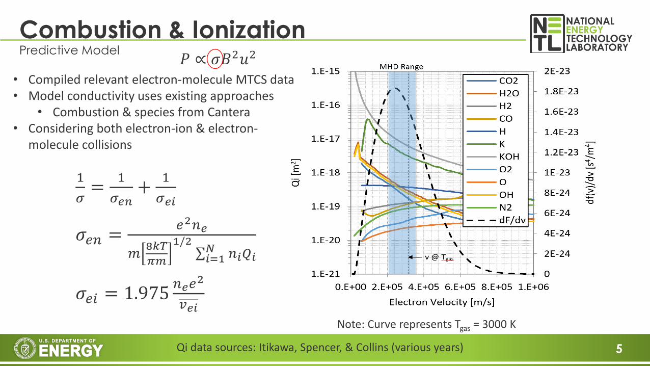
Combustion & IonizationPredictive Model
• Compiled relevant electron-molecule MTCS data• Model conductivity uses existing approaches
• Combustion & species from Cantera• Considering both electron-ion & electron-
molecule collisions
1
𝜎=
1
𝜎𝑒𝑛+
1
𝜎𝑒𝑖
𝜎𝑒𝑛 =𝑒2𝑛𝑒
𝑚8𝑘𝑇
𝜋𝑚
1/2σ𝑖=1𝑁 𝑛𝑖𝑄𝑖
𝜎𝑒𝑖 = 1.975𝑛𝑒𝑒
2
𝑣𝑒𝑖
Qi data sources: Itikawa, Spencer, & Collins (various years)
Note: Curve represents Tgas = 3000 K
𝑃 ∝ 𝜎𝐵2𝑢2

6
Comparing predictions versus legacy experiments
Combustion and Ionization
Very limited validation data• high uncertainty• disagreement between sources
Note: conductivity model presented here is slightly new and uses different H2O cross section then prior reports (and current NETL MHD 1D code results in slides).
Data Sources: Brogan (1963) & Dixit (1986)
K mass fraction

7
Combustion Validation TestingDirectly measure electrical conductivity of seeded oxy-fuel flame
• Using well-defined flame environment (Hencken burner)• 3 independent measurements needed
• Electrical conductivity via Langmuir double probe• Gas temperature via spectroscopy• Atomic potassium concentration via spectroscopy
• Full seed vaporization challenge (lab scale), Currently:• Syringe pump of ~50/50 aqueous solution of K2CO3
to O2 line• Spray solutions and discard large drops• Eliminate water droplets by diffusion drying• Thus small K2CO3 conveyed to burner w/ O2
• Langmuir probe tip durability• Trying both platinum or tungsten tips• Short insertion times, via rapid traverse system• Calibration in aqueous solutions
K Seeded Oxy-fuel Flame
8
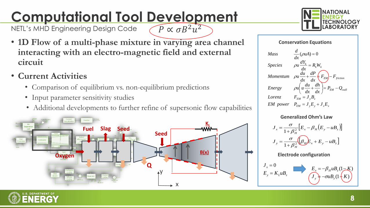
Computational Tool DevelopmentNETL’s MHD Engineering Design Code
• 1D Flow of a multi-phase mixture in varying area channel interacting with an electro-magnetic field and external circuit
• Current Activities
• Comparison of equilibrium vs. non-equilibrium predictions
• Input parameter sensitivity studies
• Additional developments to further refine of supersonic flow capabilities xxyyEM
zyEM
wallEM
frictionEM
kkk
EJEJPpowerEM
BJFLorenz
QPdx
dh
dx
duuuEnergy
FFdx
dP
dx
duuMomentum
WRdx
dYuSpecies
uAdx
dMass
0)(
zLy
x
uBKE
J
0
zyxH
H
y
zyHx
H
x
uBEEJ
uBEEJ
2
2
1
1
Conservation Equations
Generalized Ohm’s Law
Electrode configurationB(x)
KLSlag SeedFuel
Oxygen
Seed
Q
)1(
)1(
KuBJ
KuBE
zy
zHx
𝑃 ∝ 𝜎𝐵2𝑢2
y
x

9
• Compare different code outputs downstream of nozzle throat to published simulation data for H2-Air scramjet [Huang, 2015]
1D code with Finite Rate ChemistryComputational verification for non-equilibrium chemistry
• Code outputs consistent w/ literature downstream of nozzle throat
• Note temperature results (expected to impact MHD Power)

10
• Inputs
• Fuel: C12H26
• Oxidant: 100% O2
• Combustion Pressure = 3 Bar
• Seed: K2CO3 powder; K mass loading 4.94% by weight of total inputs
• Input Temperatures: 300K
• Aspects for Analysis
• Complete combustion & seed decomposition
• No wall heat losses
• Fixed Mach channel (2.1 M)
• Results
• Non-Equil chemistry important for supersonic Oxy-MHD consideration
• Equil and Non-Equil do converge for fixed Mach channel
• Results suggest seed kinetics also matter
1D code with Finite Rate ChemistryThe impact on supersonic Oxy-MHD Electrical Conductivity – An Example Problem
0
20
40
60
80
0 0.1 0.2 0.3
Co
nd
uct
ivit
y [S
/m]
Distance [m]
Non Eq Eq
0
20
40
60
80
2400 2600 2800 3000 3200 3400
Co
nd
uct
ivit
y [S
/m]
Temperature [K]
Non Eq Eq
Note simulations still assume L.T.E (Te = Tg)
11
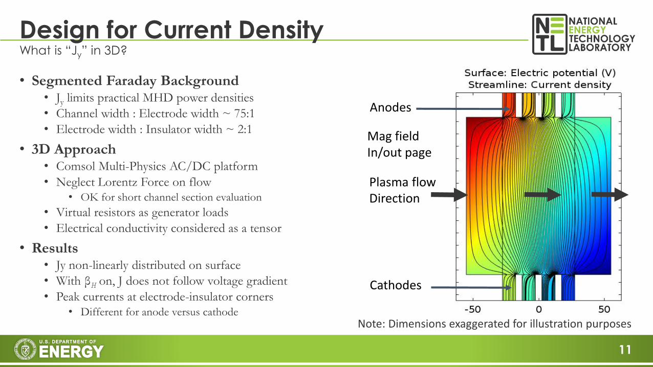
• Segmented Faraday Background• Jy limits practical MHD power densities
• Channel width : Electrode width ~ 75:1
• Electrode width : Insulator width ~ 2:1
• 3D Approach• Comsol Multi-Physics AC/DC platform
• Neglect Lorentz Force on flow• OK for short channel section evaluation
• Virtual resistors as generator loads
• Electrical conductivity considered as a tensor
• Results• Jy non-linearly distributed on surface
• With βH on, J does not follow voltage gradient
• Peak currents at electrode-insulator corners
• Different for anode versus cathode
Design for Current DensityWhat is “Jy” in 3D?
Note: Dimensions exaggerated for illustration purposes
Plasma flowDirection
Mag fieldIn/out page
Anodes
Cathodes

12
Current Density ResultsResults shown are for a “Continuous” Linear Faraday Generator
β = 0
β = 2
• B & u profiles off• Heat transfer off• Fixed plasma properties• No arcing or boundary layers• Corners filleted w/
conductivity profile• Reduces numerical
instability & error to achieve verification (next slide)
• Real system likely different (b/c arc behavior)
13
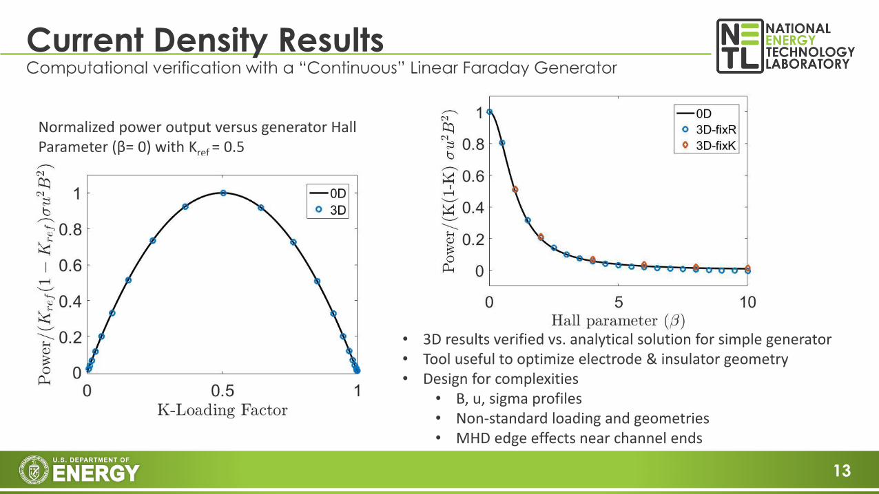
Current Density ResultsComputational verification with a “Continuous” Linear Faraday Generator
Normalized power output versus generator Hall Parameter (β= 0) with Kref = 0.5
• 3D results verified vs. analytical solution for simple generator• Tool useful to optimize electrode & insulator geometry• Design for complexities
• B, u, sigma profiles• Non-standard loading and geometries• MHD edge effects near channel ends

14
High Velocity Oxy-Fuel (HVOF) SystemCharacterizing Heat Balance in HVOF
Simulation
• Customized Praxair JP 8200 HVOF utilized• Kerosene-Oxygen Combustion• 6-8 bar combustion• ~160 kWt Input Power • Cold copper wall heat transfer
• Use calorimetric method from cooling water temperature and mass flow measurements
Cooling H2O inCooling H2O out
Kerosene
CombustionChamber
CDNozzle Barrel/Channel
AtomizingInjector
O2
Air
Exit
Establish a baseline cold wall heat transfer rate for future supersonic oxy fired MHD channels
• customized OpenFOAM model• “sonicParcelFoam”• Reaction mechs adapted for dodecane• Convective: using wall functions• (y+ = yuτ/ν ~ 2) B.L.
• Sensitivity study on-going• Radiative: P1 grey gas

15
HVOF in actionVideo from IR camera (See later slide for additional details)

16
Simulation Results of HVOFGas temperatures for Cold wall HVOF
• 1D: 1D NETL MHD code output
• 3D: openFOAM• Shocks can be
seen in 3D Temps• Maintains very
hot core ~3000K • Cross section T of
flow rapidly stratifies near HVOF exit
Combustionchamber
CDNozzle
Barrel (future MHD channel)
3D- burner center line
3D- Cross section average
1D-NonEquilib-Frozen
1D-NonEquilib
1D-Equilib
Free Jet

17
CombustionChamber
CDNozzle
Barrel (Future MHD Channel)
Simulation Results of HVOFWall Heat Transfer for Cold wall HVOF
• Peak velocities ~2100 m/s
• Peak heat flux at throat• ~700 W/cm^2
• Cold Channel Wall• ~300 W/cm^2
• Flux increases with mass flow (thermal input)

18
HVOF Total Wall Heat TransferExperiment versus simulation
• For expected stochiometric conditions, ~20% of input power went to wall cooling
• Sensitivity to mass flow changes similar for simulation and experiment
Experiment Data
• Simulation and experiment differ on conditions for peak transfer• Simulation assumes pre-vaporized fuel & pre-mixed
reactants predicts complete kerosene consumption• Experiment results suggests complete combustion may not
be fully achieved in these tests
19
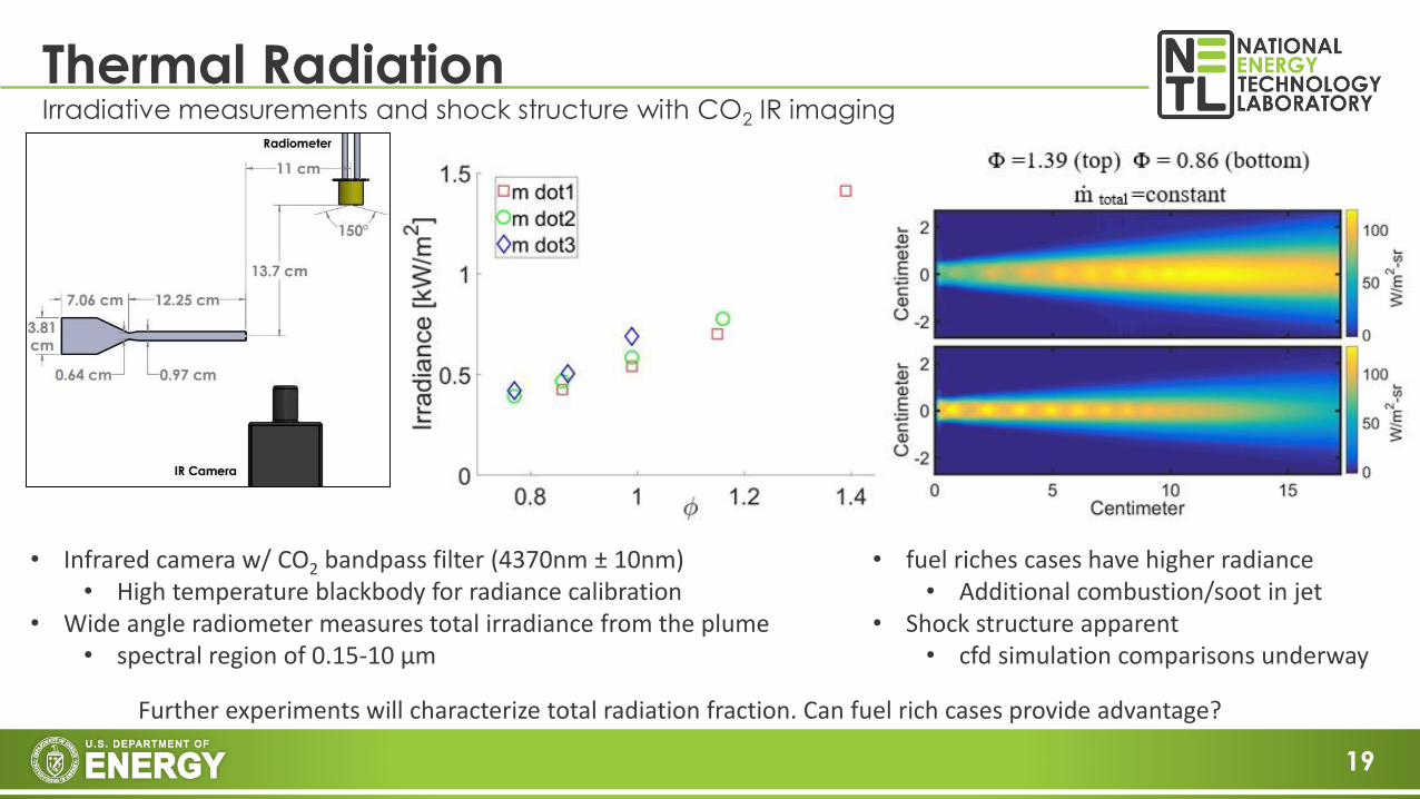
Thermal RadiationIrradiative measurements and shock structure with CO2 IR imaging
Further experiments will characterize total radiation fraction. Can fuel rich cases provide advantage?
• Infrared camera w/ CO2 bandpass filter (4370nm ± 10nm) • High temperature blackbody for radiance calibration
• Wide angle radiometer measures total irradiance from the plume• spectral region of 0.15-10 µm
• fuel riches cases have higher radiance• Additional combustion/soot in jet
• Shock structure apparent• cfd simulation comparisons underway

20
Magnesia (MgO) Rod TestDirect Insertion of high temp refractory into free jet (gross temperature check)
Custom pyrometer constructed using CCD spectrometer; Multi two-color method employed
Exposed Surface
Temperatures
Receptor to CCD Spectrometer
MgO rod surface
HVOF free jet
• Measured temperatures consistent with HVOF expectations• Technique used in materials exposure work• MgO rod does survive this test

21
PhotoionizationGeneral description and testing
• Combustion driven MHD plasma is a partially ionized system which rapidly reaches thermal equilibrium
– Very little seed introduced thermally ionizes (~1-3% of it)
• Ionization potential of K is 4.34 eV
– So “photoionization” of potassium using UV photons < 285nm
– UV source must be efficient enough to make sense for bulk ionization > 10% efficiency past gross estimate (Rosa, 1963)
• Directed energy with lasers = Good spatial & temporal control
– Boundary layer arc control and manipulation possible
• “Help” electrons travel from plasma to cooler electrode
– Due to arcs the boundary already likely in non-equilibrium
• Experimental approach
– Test set-up: Potassium seeded HVOF fired into a 2T magnet and excite with multiple pass pulsed 248nm Excimer laser.
– Initially characterize total laser absorption measurement as test conditions change
– Later apply high speed K1 Spectroscopy (<1ns acquisition times)
Shake down testing of seeded HVOF in magnet
“Lilac” color is from thermally excited K

22
Photoionization SimulationCFD Photoionization Modeling and Simulation
• Under development (in OpenFOAM)
• Customization of radiation and reaction sub-models• Photon as reactant
• Infinitely Small Weight (ISW) method for calculating laser propagation using the discrete ordinate method (DOM)
• Generalize boundary conditions for reflection and transmission
• Photon absorption coefficient is linked to photo-ionization reaction coefficient
Non-equilibrium term
Laser Intensity
Electrondensity
Preliminary Simulations of NETL Photoionization Experiment
dsssIIsIsI iiB )ˆ,ˆ(),ˆ(4
1)(ˆ)()(),ˆ()(),ˆ(ˆ
s
Radiation
MKMeK
eeKhveK
rec
photo
k
k
]][][[][]][[][][
KeMkhvKekdt
ed
dt
Kdrecphoto
Ionization

23
• Oxy-fuel combustion plasma conductivity predictions highly uncertain• Validation testing very difficult to execute but underway
• Supersonic combustion driven channels need non-equilibrium considerations• We have added this to NETL’s 1D MHD engineering code
• Hall Parameter, load factor, and optimized channel/electrode/insulator dimensional ratios are need to correctly predict power output performance• We have developed a tool which can correctly assess these complicating factors
• HVOF heat transfer rates measured are very high but simulations can predict them• Likely need much higher wall temperatures for efficient energy conversion
• Photoionization provides new options as UV laser technology develops• We are testing to obtain basic properties for this technique
Conclusions

24
Acknowledgements
This presentation was prepared as an account of work sponsored by an agency of the United States Government. Neither the United States Government nor any agency thereof, nor any of their employees, makes any warranty, express or implied, or assumes any legal liability or responsibility for the accuracy, completeness, or usefulness of any information, apparatus, product, or process disclosed, or represents that its use would not infringe privately owned rights. Reference herein to any specific commercial product, process, or service by trade name, trademark, manufacturer, or otherwise does not necessarily constitute or imply its endorsement, recommendation, or favoring by the United States Government or any agency thereof. The views and opinions of authors expressed herein do not necessarily state or reflect those of the United States Government or any agency thereof.
NETL Co-Principal Investigators: Dr. Clint Bedick, E. David Huckaby, Danylo OryshchynNETL ORISE fellows: Eric Zeuthen, Dr. Hyoungkeun Kim, Michael Redle2016 ORISE Summer Interns: Yi Hsun Yang, Brian Lovich, Dr. Duncan McGregorTechnical consultants: Dr. John Lineberry, Dr. Geo Richards, Thomas Ochs, Dr. Nathan GibsonAECOM Research Technicians & Engineering StaffNETL Management, ES&H, IT, Multi-media & Site Operations Staff