analysis tools for high performance design - texas … · · 2015-04-29evaluation of multiple...
TRANSCRIPT

csdCenter for Sustainable Development
Analysis Tools for High Performance Design
Christine V. Konstantinidis
Editor
Werner LangAurora McClain

2
II-Strategies Analysis
2.18 Analysis Tools for High Performance Design
3
main picture of presentation
Introduction
”A well designed building is most successful when it responds to its local climate through thoughtful architectural design. The more the architecture works in harmony with its environ-ment, the smaller its systems need to be.”
-Nico Kienzl
A high performance design is achieved by placing the primary focus on its ability to optimize thermal and visual comfort for its inhabitants while reducing energy consumption as much as possible. It will need to strive for facade optimization, appropriate incorpora-tion of daylight and shading, optimization of building systems, and conservation of water and resources. The way to do this is through environmental and lighting analyses, which integrate many of these aspects which are not explicitly within either the architects’ nor the engineers’ traditional scope of expertise.They can be characterized as an interaction between different disciplines with environ-mental relevance. To effectively optimize a design, creative communication and collabora-tion must take place between the architect, the engineers, and specialty consultants focused on environmental design. Several steps need to take place in order to facilitate a high performance design process, the first of which is for the designer to fully examine and
understand the environmental implications of their proposed design. This can be achieved through performing detailed analysis of energy, daylight, air flow, and other relevant factors.
Although analysis and computational tools have reached a level of sophistication that allows us to evaluate a proposed design at different stages of the design process, there are still major misconceptions about what these tools can do and how they can be best applied to a project. The following examines the basic principles of the high performance design process using analysis tools, supported by several case studies which demonstrate the importance of these analysis tools in practice and serve to deepen the understanding about their contribution to the design process.
Designing toward a carbon positive development
One of the most basic questions that needs to be answered in building design is, “What must be achieved in order to provide shelter?” This is a problem that should be examined in a very integrated way, not by limiting design ideas, but rather by proposing designs that are simple and robust in terms of technical feasibil-ity. Good solutions will work for a long period of time and also push us closer to fully imple-menting sustainable building infrastructure. These buildings will be a part of their natural environment. Instead of posing harm for future
Analysis Tools for High Performance Design
Christine V. Konstantinidis
Based on a presentation by Nico Kienzl
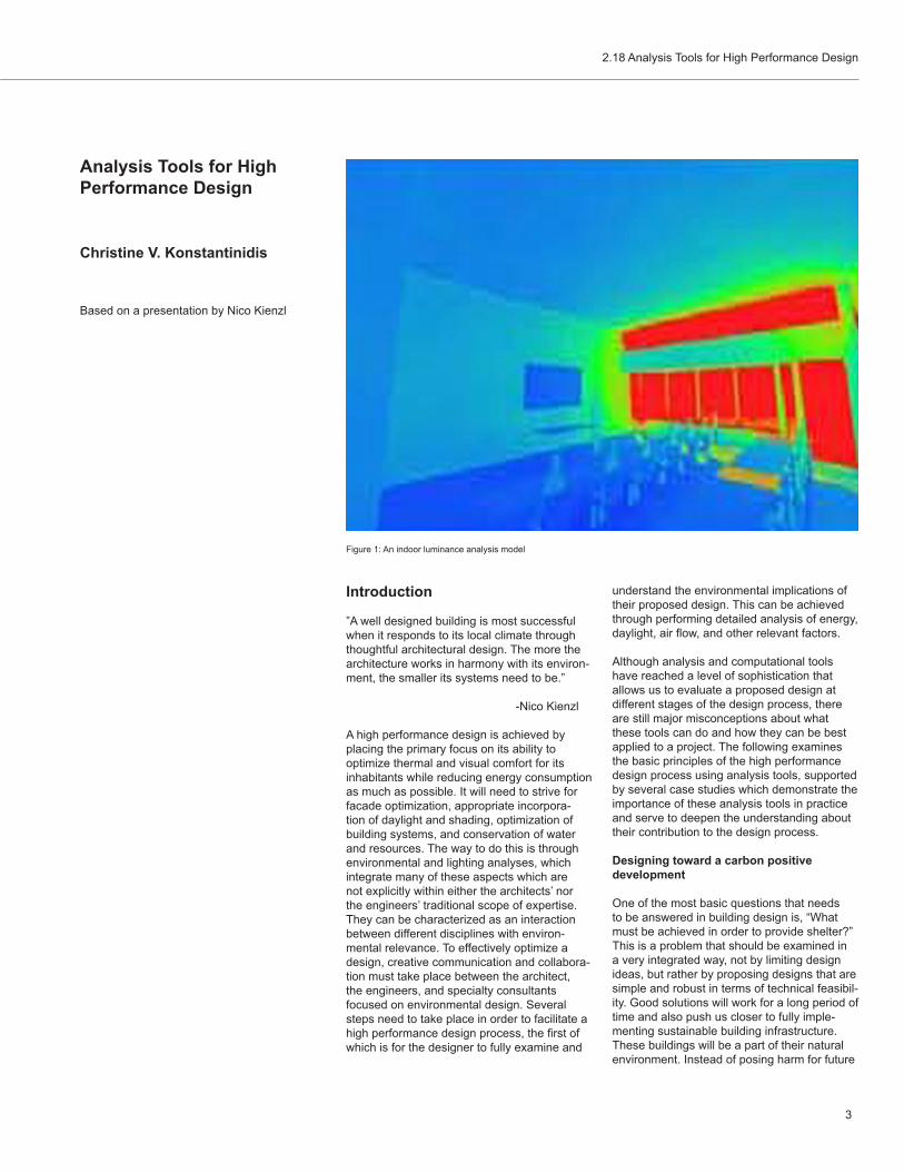
Figure 1: An indoor luminance analysis model

4
II-Strategies Analysis
generations, they will truly become part of the earth’s natural cycle. Environmental sustain-ability must be integrated with aspects of social and economic sustainability in order to achieve successful solutions in this direction. This integration constitutes a very complex evaluation of multiple variables, which initially contain building energy efficiency, air quality, water, materials, economy, and transport.
The primary goal in this process is to move away from a conventional approach to design that looks only at the energy going into the building, and instead, to move toward a method that looks toward larger boundaries, taking into account aspects that might not be seen at a building level but will be noticed at a higher level. In this case, energy should be considered at a systematic infrastructure level, with the building as the principal interface.
Considering carbon emissions as a measure-ment of environmental sustainability, there is a relatively clear path for successfully moving towards carbon positive development. Begin-ning with a conventional design that fulfils the building’s functional requirements, several questions are brought up during the design process. First, what is the climate in which the building is situated, what degree of shelter is required, and how much of this can be achieved by the building envelope? Second,
how can this shelter be conditioned in the most efficient way? Third, where does the energy needed for conditioning come from, and what can be done to mitigate any environmental impact that is associated with this energy gen-eration? The goal of this process is to achieve a carbon neutral design. Adding renewable energy strategies, such as photovoltaics and wind power, can lead to the desired carbon positive development.
A lot of people start this investigation from different standpoints, some beginning with the assumption that green buildings need to have complex renewable strategies applied to them, but overlooking aspects of architectural design that can both be meaningful and lead to a more energy efficient building.
Where design diverged from nature
Traditionally, human shelters had to be very climate responsive, taking advantage of all available natural resources. The functions of different structures have added to the richness of the architecture for a very long time. For example, the Flatiron building in New York was shaped, to a certain extent, by the conditions of the local climate as much as by available technology. It is a relatively shallow building, designed to maximize daylight and cross-ventilation, with punched windows and minimal
glazing. It originally had fabric awnings that could be lowered to shade the building during the hot, humid New York summers. This pro-cess of developing climate responsive design shifted in the 1950’s, when the development of refrigeration, the use of large panes of glass, the innovation of light steel construction, and engineering systems allowed architectural design to function independently of natural climate and surroundings, therefore resulting in architecture that is leading to increasing environmental problems.
The questions now are, “How can climate re-sponsive architecture make a comeback? How modern buildings satisfy their modern func-tional requirements, and still have the smallest environmental footprint possible?” Key to finding this solution is placing an emphasis on integration between the building and its sys-tems through developing an understanding of the interdependency of the various elements. A lot of buildings designed during the last thirty to fifty years have done just the opposite: architects designed the architecture and then engineers put in the HVAC system. The con-nection between the two disciplines has been lost, although they should be fundamentally connected. The common practice in this case is that energy loads are determined by archi-tects and systems are subsequently optimized by engineers, while the necessary approach,
Figure 2: Design process toward carbon positive development

2.18 Analysis Tools for High Performance Design
5
enabled by the power of new analysis tools, is to look at the complex interdependency between these two systems iteratively.
When considering the goals and expecta-tions for a project, the initial step is to set targets that can be measured, evaluated, and improved. If the set target is just a vague goal, like becoming more energy efficient, it is very difficult to measure progress and see what has been achieved compared to what was intended.
Analysis Tools
In order to achieve significant savings in money or energy, the majority of the decisions should be made very early in the design pro-cess. The initial sketches that determine the massing of a building, the attitude toward the building enclosure, and the type of condition-ing system all set the stage for the energy that will be used later on. At the same time, changes made later on in the design process require a lot of effort for decreasing return. The challenge is figuring out how best to use simulation and analysis tools effectively early in the design. In the schematic design phase, a lot of variables are unknown and a lot of assumptions must be made in order to arrive at meaningful analysis results. The integrated use of multiple analysis and visualization tools throughout the building design process, from the initial, schematic phases to the detailed specification of building components, can be very powerful. Over the last two decades, en-gineers have tended to focus on optimization of systems, for energy efficiency, later in de-sign, often during construction documentation, instead of the early design phases, due in part to the traditional split between the disciplines.
There are new tools that address ever more complex building systems and build-ing behaviors, ranging from active thermal mass or chilled beams, to different ways of air distribution or hybrid systems that aid in natural ventilation. There is an increasing push in the industry to tie analysis tools into building information management tools. The typical drawback with these tools is the lack of user experience, which generates problems with respect to controlling the data and customizing the needed analysis. Almost every structure can be modeled and analyzed, even though there are a lot of assumptions that have to be made. The most challenging aspect of building analysis is that it requires a sophisticated, broad, and deep knowledge, because of the complexity of both the systems and the physi-cal phenomena involved. Several organiza-tions, such as the US Green Building Council, are encouraging the development and use of
building energy analysis tools, through bench-marking systems that require measurement of energy efficiency relative to code baselines.
Data interpretation is key to the relevance of analysis. The analysis performed can be either qualitative or quantitative. Qualitative analysis basically establishes advantages and drawbacks, while quantitative analysis allows for comparison with other buildings and leads to references based on this comparison. A significant advantage of dealing with computer analysis is that numerical results and data can be used for a meaningful conversation about building efficiency. Often questions arise about how accurate and valid the analysis is. It is common for the numbers generated from different analysis stages to look as if they are absolute, despite the enormous number of as-sumptions made during the analysis process. It is therefore dangerous to have a quantitative analysis that does not clarify the assumptions built into it. One of the major challenges of building simulation is, therefore, the ability to present and understand the generated infor-mation in a very sophisticated way, so as to make it meaningful.
The main types of analysis involved in building design, include energy analysis, lighting and daylight analysis, and air flow analysis.
Energy analysis
Energy simulation in buildings examines en-ergy gains, losses, peak loads, total consump-tion, and intensity. Energy analysis is used both for optimization and equipment sizing. For optimization, total annual energy use, energy cost, and carbon emissions are the most criti-cal indicators and can be used to optimize both architectural systems (facades, massing, etc.) as well as mechanical and electrical systems (HVAC system type and operation, control strategies, etc.). This analysis is also the basis for performance based compliance calcula-tions, such as the energy standard ASHRAE 90.1. When sizing equipment, the mechanical engineers are using simulation to determine peak loads to make sure that heating, cooling and ventilation equipment is appropriately sized to meet the conditioning demand. The difference between the two approaches is that optimization is looking at realistic aver-age annual conditions, while sizing tends to analyze heating and cooling loads sustained during worst case scenarios exclusively. In both cases, comfort criteria are a key driver as they determine conditioning requirements. Sophisticated analysis can correlate energy consumption and comfort in a way that allows clients and designers to evaluate tradeoffs.
Lighting analysis
Light and especially daylight are also major factors to consider when optimizing and modeling systems, since a significant amount of energy is consumed for electric lighting, as well as for cooling caused by undesired solar heat gain. Available analysis tools are very useful to look at lighting in a quantita-tive way, optimizing the available daylight in order to minimize electric lighting. Illumination, luminance, comfort, and energy used are all examined.
Air flow analysis
Air flow analysis or Computational Fluid Dynamics (CFD) considers the dynamic dis-tribution of air due to pressure or temperature differences. It can be used to evaluate ventila-tion effectiveness as well as comfort criteria such as air speed, humidity distribution, and temperature.
Integration with the design process
A number of significant questions need to be answered even before analysis can start. Does the analysis need to show relative differences, or absolute magnitudes? What level of detail and accuracy of the context information is available to inform the analysis? What level of detail and accuracy is needed for a meaning-ful analysis? Does enough information exist to validate the analysis results? Is the ap-proximate answer known before beginning the simulation? Are the strengths and weaknesses of the tools known? Is there benchmark data available to compare results with? What is the simplest way to construct the analysis? In what context should the results be reviewed?
It is very important to be have a good under-standing of what is being analyzed and what the potential results might be, before perform-ing any simulation. This way, results can be put into context and errors can be reduced both in the simulation and in the interpretation. Another key step is to simplify the analysis as much as possible without limiting its accuracy in order to reduce the number of variables, consequently increasing simulation speed and improving results by focusing the analysis on the key aspects under investigation.
There are number of stages in the design process that lead to an integrated and high performance design: • The Pre-Design stage attempts to under-
stand the overall project requirements and the local climate. This is also the time to identify appropriate benchmarks for

6
II-Strategies Analysis
ing would have let to overheating and/or very high energy consumption for cooling. Analysis was performed with the intent of generating an alternative skin strategy that would help to mediate excessive solar heat gain while still preserving the desired architectural expres-sion and views. The design process contained a deep understanding of the architectural precedents in the area and other technology constraints. Sketches and models generated an idea for a space frame that could serve as the structure and support external shad-ing fins. Due to the complex geometry of the architectural shape, the external fins vary in geometry around the building to allow views outside while still providing the maximum amount of shading.
The key goal of the analysis was to establish what the shading fin geometry would be. The first step was to examine the solar path over the building in Singapore, an important factor, considering its location close to the equator. The next step was to generate a strategy that would provide maximum shading over the varying geometry of the building. A simple analysis provided shading angle calculations for the various surface orientations of the building, once the annual sun angles for the area had been determined. The result of this analysis was geometry with a limited number
Figure 3: Esplanade Theatres, Singapore
the project and to establish the goals and ambitions of the design.
• The Schematic Design stage looks at performance studies, such as overshad-owing studies or the analysis of major HVAC system options, to establish the big design drivers. Often this work is carried out with relatively abstract models (such as a typical space or a massing model of the building) to allow for quick design iterations. At this stage, the compatibility of the generated results with the initial goals of the pre-design phase should also be examined.
• The Design Development stage involves more refined analysis and typically involves detailed whole building analysis for energy optimization and more refined special analysis for more complex issues (like natural ventilation or façade optimi-zation). In this phase, projected operating cost can be used for more detailed life cycle analysis and payback calculations to test the economic tradeoffs of various options.
• Construction Documentation constitutes component testing, controls testing and optimization of the building components.
The earlier assumptions in the model start to be reduced at this stage and are replaced with actual performance infor-mation associated with the equipment and components installed.
• Construction Administration is the phase where the transformation of the model to as-built conditions is performed and often where the final simulation for LEED (or other applicable benchmarking system) calculation and documentation occurs.
• Post Occupancy contains the examina-tion of the building performance and comparison of the generated results to the predicted performance
Case studies
Esplanade Theatres, Singapore
Architect: Michael Wilford & Partners and DPAProject status: completed 2002
The project consists of two performance spaces on Marina Bay in Singapore, designed to have transparent glass structures housing the theatre and the concert hall. The initial de-sign idea called for a fully glazed design. In the hot climate of Singapore, a fully glazed build-
Figure 4: Detail of the fins in Esplanade Theatres, Singapore

2.18 Analysis Tools for High Performance Design
7
it ascends with an external skeleton supporting horizontal shading fins. The shading fins are very important to the architectural expression of the tower as they allow for high degrees of glazing and provide architectural texture to the skin. The goal of the analysis was to deter-mine the depth of the shading fins required to achieve optimum building shading and reduced direct solar gain.
The analysis was based on a very simple model, simplifying the building as a cylinder, so that all the orientations could be examined. The analysis process initially modeled different shading strategies with different cutoff angles for fins in front of each plane. Using Ecotect, the reduction in solar gain on each of these orientations was determined over the year. The study generated a graph showing the incident solar radiation for each orientation, with the average total and the peak total shaded and unshaded incident radiation on the surface. By looking at various cutoff angles, the degree of radiation reduction that could be achieved for each orientation was determined. The advantage of the very simplified model was that the analysis could be repeated for many different fin depths very quickly. This provided a complete picture of the behavior of the shad-ing system for all orientations. Finally, a cutoff angle for each orientation was recommended
and the optimal vertical spacing and depth of the fins was determined. Subsequently, a parametric model of the building was created, and these relatively simple rules concerning the cutoff angle for each orientation were inte-grated into the very complex overall architec-tural model.
Energy and daylight analyses of the design were also performed, in order to predict the amount of energy saved by shading the build-ing. An energy analysis of only one apart-ment was enough to provide guidance on this issue. Additionally, the single apartment was very easy to rotate, allowing evaluation of its performance in various orientations to be generated relatively quickly. A visualization of the daylight coming into the apartment was also used to make the results more accessible. Daylight renderings often can help to provide a relatively quick understanding of the quality of light in a space.
Comcast Center, Philadelphia
Architect: Robert M. Stern, NYProject status: completed 2008
The Comcast Center is the tallest tower in Philadelphia,. The signature feature of the building is a eight-story winter garden on the
of different fin types applicable to the various orientations of the building. Each fin had the same base dimension but a different height to its tip, so that the orientation of that surface relative to the sun angle would provide the maximum amount of shade.
The strategy of varying the fin geometry around the building creates very controlled views from inside to outside, while at the same time providing almost complete shade for the building without destroying its dynamic architecture. The fins on the Esplanade The-atres have become an iconic design feature in Singapore, achieving the fundamental goal of integrated design: creating solutions for buildings that do not hamper the design, but rather bring richness to architecture by making it climate responsive, locally responsive, and richly textured.
Al Raha Tower, Abu Dhabi
Architect: Asymptote, NYProject status: expected to be complete by 2011
This residential tower, designed by Asymptote architects of NY, is currently under construc-tion in Abu Dhabi. It has a unique geometry, formed from a three pointed star twisting up as
Figure 5: Al Raha Tower, Abu Dhabi Figure 7: Atrium design elements to achieve thermal comfortFigure 6: Comcast Tower

8
II-Strategies Analysis
a double skin façade or the top of the space. Additionally, displacement ventilation was introduced to bring cool air directly to the occupied zones on the ground floor and the balcony level. This way, warm air could stratify up and both fan power and air volumes were greatly reduced by only comfort conditioning occupied areas. Furthermore, heating ele-ments in the façade were designed to reduce downdraughts and meet winter heating loads. This solution introduced too many variables (all the systems, their relative performance, and controls in respond to changing climate), for traditional sizing calculations to be used. The need to maintain thermal comfort within the space, while meeting heating and cooling loads, resulted in many potentially conflict-ing requirements for both summer and winter periods.
In setting up the analysis, two things needed to be understood: the amount of energy coming into the atrium and how it would affect comfort in the lower part of the space where people would be sitting. The first aspect required information on how much solar gain occurs in the six-story winter garden. For this, a model of downtown Philadelphia was created to examine the overshadowing of the building by the surrounding structures. Subsequently, various points on the floor of the atrium were mapped and shadow masks were developed based on the solar path over the year and the shadows cast by the surrounding buildings. The superstructure, the shading devices, the façade structure, and the various design ele-ments were then layered, to develop a more complete understanding of the true over-
front elevation of the building, which is used for public events.
The biggest challenge for this project was devising and optimizing the system that would comfortably condition this tall and highly glazed space, without building up condensa-tion, while still preserving its transparency, openness, and daylight access to the building. The traditional solution for this scheme would be to use overhead air conditioning in order to make the space comfortable, compensating for high solar gains in summer and high thermal losses in winter. The fundamental challenge was to use analysis to determine whether com-fort could be achieved with this system in such an unusual space. The exterior of the atrium was made of glass, so there was only one side from which air could be introduced. Also, the space is very tall, especially at the front of the building where the winter garden reaches up to the 8th floor. This created serious doubt about the possibility of achieving internal comfort with an overhead supply system and would have required high energy use to push very large volumes of air into the atrium to meet the heating and cooling loads.
The strategy suggested involved the use of a hydronic radiant floor system to remove some of the solar load in the summer and to provide radiant heating in the winter. Addition-ally, the use of high performance LowE glass was suggested, in combination with a fixed external canopy and deep mullions that would act as internal fixed louvers for solar control. This way, solar gains could be reduced in the occupied zone by ventilating air out through
shadowing conditions for the building. Solar exposure studies were then examined.
The overshadowing analysis was carried out in Ecotect, which is a good tool for geometric models, visualization, and solar analysis. The winter garden geometry was then separated into thermal zones and modeled in TRNSYS, a thermal analysis tool that is good at modeling the thermal behavior of spaces with complex radiant exchange, thermal mass, and complex bulk air flow. TRNSYS is an extremely flexible tool that provides very detailed results of the physical properties analyzed, but is not well suited to modeling complex geometries as the one ECOTECT used to create shading masks. TRNSYS made it possible to see the tempera-ture stratification in the space, as well as the comfort levels in the space. It also allowed the testing of different glass types and a com-parison of the energy consumption needed for water or air heating and cooling based on different glass types. The goal of this analysis was to determine whether the space could be kept within the comfort range for a reasonable number of hours given the proposed strate-gies.
In this case it was also important to look at the supply air temperature, the resulting air temperatures and velocities in the space, and the air movement close to the facade, instead of looking only at the energy consumption. Neither TRNSYS nor Ecotect can model such detailed flow behaviors. Therefore, a com-putational of fluid dynamics (CFD) analysis was performed for the winter garden to verify comfort conditions based on a more detailed
Figure 8: Downdraft analysis of Comcast Center in Ecotect Figure 9: Greenspun College of Public Affairs

2.18 Analysis Tools for High Performance Design
9
Figure 11: Kroon Building, Yale School of Forestry
understanding of the air movement in the space. This analysis showed that without the façade heating elements and the partial double skin, the air close to the façade would cool down too much and accelerate down to the floor resulting unacceptable comfort conditions due to high air velocities and low air tempera-tures on the floor of the winter garden. The study thus confirmed the solution proposed of having a partial double skin façade introduce warm air at the midpoint of the façade and providing heating elements along the facade to prevent downdraughts even in the most severe winter conditions.
Greenspun College of Urban Affairs, Uni-versity of Nevada, Las Vegas
Architect: HKS Architects Inc. in association with Robert A. M. Stern ArchitectsProject status: completed 2008
The Greenspun College of Urban Affairs provides a good example of a comprehensive integrated design process. The structure com-prises faculty offices, classrooms and media production spaces grouped around a central open courtyard.
The climate in Las Vegas is hot and very dry, with high levels of solar radiation. Outdoor public spaces therefore tend to be much more successful when they are shaded. One early stage design idea, using this understanding of the climate, attempted to shade the public outdoor space in addition to shading the build-ing with external shading and a limited use of glazing. It was critical to find the right balance
between reducing cooling loads and maximiz-ing useful daylight. For this reason, single of-fices were modeled in Ecotect with overhangs and different amounts of glazing, to determine the daylight factor, a ratio of outside available light to inside available light, as well as daylight distribution in the space. This showed that a relatively low glazing percentage with external shading would still allow enough daylight into the space.
To establish benchmarks for the energy ef-ficiency of the building, the energy consump-tion of an average US academic building, a code compliant building, a good practice compliance building, and a high performance academic building were compared. An early target for this project was set between the high performance building and the good practice compliant building. To achieve this target, more detailed energy analysis was performed and revised for the building throughout the design process. A detailed model comprised of nearly 150 thermal zones was built. These zones rep-resented all the different spaces in the building with their respective schedules, loads, orienta-tions, and system types. Once the model was built, it was relatively easy to modify variables, one parameter at a time, to observe the cor-responding change in the performance of the building. This allowed comparison of the changes achieved by adding insulation, shad-ing, or better glass to the building. Multiple energy systems were also examined, such as different HVAC system configurations, CO2 and occupancy sensors, and lighting systems, until approximately thirty or forty individual measures and their combinations where tested
for this building.
One of the key aspects in this project was the HVAC system. A strategy suggested from the beginning was the use of chilled beams for offices and classrooms, which would move cold water through ceiling-mounted devices to provide local cooling, and introduce a limited amount of outside air for ventilation purposes. Selecting this alternative type of cooling system resulted in a significant decrease in energy consumption and operating cost.
In the end, the building’s energy demand was projected to be 50% lower than an ASHRAE 90.1-2004 code compliant building. Adding to the energy efficiency of the building, photo-voltaics were installed over the courtyard. These generate approximately 40% of the total electrical needs while also creating the desired shaded outdoor public space. This project was a great example how the use of analysis tools can lead to significant reductions in energy consumption in a building through the improve-ment of several aspects of the design.
Kroon Hall, Yale School of Forestry & Envi-ronmental Studies
Architect: Hopkins Architects/Centerbrook ArchitectsProject status: completed 2008
Kroon Hall, located on a sloped site on Yale University’s Science Hill, had the primary de-sign goal of pushing a carbon neutral building design as far as technical feasible. The build-ing is oriented in an east-west direction with
Figure 10: Greenspun College of Public Affairs

10
II-Strategies Analysis
a very narrow east-west elevation to reduce summer solar heat gains, with faculty offices along a central corridor and common spaces on the top floor. The notion of a high perfor-mance building envelope with well balanced areas of high performance glazing that would reduce heat gain and loss was integrated into the architectural concept from the very begin-ning of the design process. The design had glass where needed to allow external views and at the same time admit daylight into the building. External shading was then added where required to reduce unwanted solar gain. For example, external timber louvers shade the east and west façades. Additionally, a highly insulated enclosure reduces conduc-tive heat losses and extremely tight construc-tion reduces infiltration. A unique roof shape designed to accommodate photovoltaics completes the architecture. The overshadow-ing diagrams of the building were examined in Ecotect to verify shading performance. A more complex daylight analysis was performed in Radiance to optimize the daylight distribu-tion in the building and to achieve the level of daylight needed in the building.
A complex HVAC system was also evaluated. The desire was to turn off the air condition-ing when outside conditions allowed natural ventilation. All of the windows were designed with sensors indicating whether they should be opened or not. An exposed concrete ceiling was constructed so that the thermal mass could reduce daily temperature swings. A high performance underfloor ventilation system with enthalpy heat recovery was integrated to reduce energy consumption and improve air quality. In addition, the building is connected to a ground source heat pump system to provide efficient heating and cooling without the need to combust fossil fuels on site.
Many models were used to see evaluate potential renewable energy sources for the project. Analysis was performed in Ecotect to test the extent to which it was feasible to use photovoltaics on the roof. The location of the photovoltaic panels was then optimized to take advantage of the unique and complex roof shape. Once all the systems where optimized, the system photovoltaics are able to produce a third of the total energy consumed in the building. Solar hot water panels were also integrated into the façade in places where they could absorb low angle winter sun to provide hot water to the building. The application of wind turbines was explored, but in the end it was decided that it would be more advanta-geous for Yale to forgo relatively inefficient small scale wind power in exchange for a larger installation off-campus.
The results of the energy analysis, when
compared with the energy performance of some recent US high performance academic buildings, showed a significant decrease in the amount of purchased electricity, with the remaining energy being renewable or solar. The decrease in CO2 emissions was also sig-nificant, generating 66% less than an average US academic building. It responds to the local climate, its orientation is in harmony with its site and climate, and its materials reflect a lot of Yale’s architecture while still having a mod-ern twist. Kroon Hall is considered a significant success for Yale and paves the way towards a low carbon future.
Conclusion
Building simulation is becoming widely recog-nized as a very important factor in the design process. Simulation tools enable designers to better understand the relationship between buildings and their environment. At the same time, they make the design and construction of sustainable and high-performance buildings easier and more efficient. Some of the existing tools are relatively familiar and easy to use, while others get more sophisticated throughout the design process. It is therefore very impor-tant to be cautious when performing complex building simulations, since the results gener-ated are directly resultant of the input data and demand a high level of technical knowl-edge and understanding. The green software industry has moved forward during the last few years by generating new software and analysis tools that lead towards a more sustainable and integrated method of design.
Resources
http://atelierten.com
http://www.atelierten.com/ourwork/profiles/0237-splanade-singapore.pdf
http://www.building.co.uk/story.asp?sectioncode=284&storycode=3114030
http://www.libertyproperty.com/sus-comcastasp?sel=3&id=1 http://research.unlv.edu/innovation/issues/spring2008/pdf/002_DEPT_OnCampusGreen-spun.pdf
Figures
Figure 1: Courtesy of Nico Kienzl
Figure 2: Courtesy of Nico Kienzl
Figure 3: http://www.esplanade.com/about_the_centre/image_gallery/index.jsp#
Figure 4: http://www.esplanade.com/about_the_centre/image_gallery/index.jsp#
Figure 5: http://www.building.co.uk/story_at-tachment.asp?sectioncode=0&storycode=3114030&seq=6&type=P&c=1&story=1&hastext=1
Figures 6-8: Courtesy of Nico Kienzl
Figure 9-10: http://urbanaffairs.unlv.edu/build-ing_gallery/greenspun.html
Figure 11: http://environment.yale.edu/kroon/index.php
Biography
Nico Kienzl is a director with atelier ten and serves as the principal building physics analyst for the New York practice. His research work has focused on performance modeling of transient building behaviors, advanced building systems, and materials for environmentally re-sponsive building enclosures. Nico previously worked as an architect with Herzog+Partner in Germany on a number of innovative low en-ergy signature buildings that integrated double skin facades, daylighting, thermal mass and natural ventilation.
Currently he teaches courses on environmen-tal systems and building systems integration at Pratt Institute’s graduate architecture program as well as at Columbia University’s Graduate School of Architecture, Planning and Preserva-tion. He has held previous teaching appoint-ments at Harvard and the Boston Architectural Center. Nico is a LEED™ accredited profes-sional and holds a Dipl. Ing. in Architecture from the Technical University in Munich, an M.S. in Building Technology from MIT and a Doctor of Design from the Graduate School of Design at Harvard University.

2.18 Analysis Tools for High Performance Design
11
