analytical model of nuclear environmental effects with ... … · analytical model of nuclear...
TRANSCRIPT

ANALYTICAL MODEL OF NUCLEAR ENVIRONMENTAL EFFECTS WITH PIEZOELECTRIC WAFER ACTIVE SENSORS
Bin Lin, Lingyu Yu, Victor Giurgiutiu
University of South Carolina Columbia, SC 29208, USA
Matthieu Gresil University of Manchester
Manchester, UK
Adrian E. Mendez Torres Savannah River Nation Laboratory
Aiken, South Carolina, USA
ABSTRACT The increasing number, size, and complexity of nuclear
facilities deployed worldwide are increasing the need to
maintain readiness and develop innovative sensing materials to
monitor important to safety structures (ITS) for pipe and
vessels (PVP) application. For example, nuclear dry cask
storage system (DCSS) is a safety-critical facility in need of
monitoring over prolonged periods of time. Technologies for
the diagnosis and prognosis of PVP systems can improve
verification of the health of the structure that can eventually
reduce the likelihood of inadvertently failure of a component.
The past two decades have witnessed an extensive sensor
technology development using permanently installed
piezoelectric wafer active sensors (PWAS) for structural health
monitoring (SHM). PWAS have emerged as one of the major
SHM technologies developed particularly for generating and
receiving acousto-ultrasonic waves for the purpose of
continuous monitoring and diagnosis. Durability and
survivability of PWAS under nuclear environmental exposures
has been tested preliminarily. However, the analytical model of
PWAS based sensor and sensing system has not been developed
with adequate solutions and guideline. This paper presents a
study on an analytical model of nuclear environmental effects
with PWAS. Environmental variability of a Nuclear-SHM
system includes changes in both the sensors and the sensing
methodology including acoustic emission (AE), guided
ultrasonic waves (GUW), and electro-mechanical impedance
spectroscopy (EMIS). We considered the environmental
variability considers the effects of temperature changes and
radiation. We superposed these changes on the analytical
models and determined how much the structural sensing signals
change is due to these environment effects for the DCSS
system. The analytical modeling of various structural sensing
methods to environmental disturbances was studied and the
potential of PWAS as irradiation sensors for PVP applications
was explored. The paper ends with conclusions and suggestions
for further work.
INTRODUCTION Many pressure vessel and piping (PVP) systems are safety-
critical facilities in need of monitoring over prolonged periods
of time. Structural health monitoring (SHM) is an emerging
technology that aims at monitoring the state of a structure
through the use of networks of permanently mounted sensors.
SHM technologies have been developed primarily within the
aerospace and civil engineering communities. However, SHM
concepts and methodologies could be extended to other safety-
critical systems. Many PVP applications, as for example,
nuclear power plants (NPP) and nuclear dry cask storage
systems (DCSS) are safety-critical facilities in need of
1 Copyright © 2014 by ASME
Proceedings of the ASME 2014 Pressure Vessels & Piping Conference PVP2014
July 20-24, 2014, Anaheim, California, USA
PVP2014-28887

monitoring over prolonged periods of time. One of the key
aspects of improving the reliability, sustaining the safety, and
extending the life of current PVP is to develop technologies that
can better diagnose their state of structural health.
SHM is an emerging technology that uses in-situ sensory
system to perform rapid nondestructive detection of structural
damage as well as long-term integrity monitoring. The
permanently installed (embedded) sensors can probe the
structures at any time over the entire service life, which is
superior to the handheld conventional ultrasonic nondestructive
testing (NDT) techniques. Combined with appropriate data
analysis algorithms, SHM can further provide timely
information regarding the structural integrity for condition
assessment and diagnosis of components important to safety
(ITS) at any time. Hence, the integration of a nuclear SHM
system into a nuclear spent fuel storage system will facilitate
the evaluation of degradation and aging of used nuclear fuel
containers and storage facilities over extended storage periods.
Eventually, it will ensure a systematic methodology for
assessing and monitoring nuclear waste storage systems
without incurring human radiation exposure. The primary goal
of in-situ sensing of structural components is to reliably
interrogate large areas and detect structural anomalies.
However, when applied to nuclear environment, even the
relatively less harsh DCSS situation, prolonged exposure to
nuclear radiation as well as elevated temperature may introduce
measurement artifacts and significant damage to both sensors
and the sensing system. In fact, the effects of nuclear
environments on this technology are not yet well addressed and
understood. The nuclear radiation on SHM systems with PWAS
exposed to irradiation effects has been tested preliminarily.
However, the analytical model of PWAS based sensor and
sensing system has not been developed with adequate solutions
and guideline. It is of paramount importance to assess and
understand how the piezoelectric ultrasonic SHM systems are
affected by nuclear radiation and high temperature factors; thus
to protect them when necessary.
This paper addresses the issue of analytical modeling of
nuclear environmental effects in PWAS SHM system. Our
focus is mainly of PVP application in the DCSS system. This
paper discusses some of the challenges associated with the
nuclear effects on DCSS system. Fundamental research
including the transition of SHM technologies to PVP
applications is discussed.
DRY CASK STORAGE SYSTEM SAFETY ASSESSMENT NEED Following the issuance of the Blue Ribbon Commission (BRC)
on America’s Nuclear Future Final Report in 2012, interim
storage of spent nuclear fuel from reactor sites has gained
additional importance and urgency for resolving waste-
management-related technical issues. In total, there are over
1482 dry cask storage system (DCSS) in use at US plants,
storing 57,807 fuel assemblies. On July 12, 2011, the Nuclear
Regulatory Commission (NRC) issued recommendations on
how to enhance “spent fuel makeup capability and
instrumentation for the spent fuel pool”. This includes the
recommendation to provide sufficient safety-related
instrumentation (able to withstand design basis natural
phenomena) to monitor from a control room the key parameters
of the spent fuel pool (e.g., temperature, radiation level, etc.).
Monitoring has been identified by DOE as a high priority cross-
cutting need. Monitoring is necessary to determine and predict
the degradation state of the systems, structures, and
components (SSCs) important to safety (ITS) and is required by
regulation (10 CFR 72.122 and 10 CFR 72.128). Revisions to
NUREG 1927 suggest requirements for monitoring and
inspection of dry storage systems as part of aging management
plans. To ensure that nuclear power remains clean energy, safe,
long-term management of used nuclear fuel and high level
radioactive waste “remains a national priority”.
Therefore, nondestructive structural material degradation
and condition monitoring is in urgent need and must be
integrated into the fuel cycle to quantify the “state of health”,
and more importantly, to guarantee the safe operation of
existing nuclear power plants (NPP) and radioactive waste
storage systems (RWSS) during their predicted life span.
Innovative approaches are desired to evaluate degradation and
aging phenomena of used fuel containers and storage facilities
under extended storage. To meet the ever-growing awareness of
nuclear safety, a state-of-the-art nuclear structural health
monitoring (N-SHM) system is necessary that uses in-situ
sensing technologies to monitor material degradation and aging
for DCSS canister and similar structures (e.g., wet storage
pools), as conceptually illustrated in Figure 1.
Fig 1: Sensor cluster on typical dry cask storage system
(http://www.nrc.gov/waste/spent-fuel-storage/diagram-typical-
dry-cask-system.html)
Sensor
cluster
Sensor
cluster
2 Copyright © 2014 by ASME

PIEZOELECTRIC WAFER ACTIVE SENSORS The key technology to an effective N-SHM system is the
sensing element that can detect the degradation under the harsh
nuclear DCSS environment. The past two decades have
witnessed an extensive development of SHM sensor technology
[3]-[5]. A wide range of sensors have been developed
particularly for generating and receiving acousto-ultrasonic
waves. Piezoelectric wafer active sensors (PWAS) have
emerged as one of the major SHM technologies. A variety of
damage detection methods can be applied to this type of sensor
[3]: (a) propagating ultrasonic waves, both acoustic emission
(AE) and guided ultrasonic waves (GUW); and (b) standing
ultrasonic waves, i.e., electromechanical impedance
spectroscopy (EMIS) as illustrate in Fig 2 and Fig 3.
AE for crack initiation has been shown to enable the
detection of crack initiation and crack progression; AE
provides earlier warning of impending damage than
any other methods. Because it is very sensitive to
damage events, the AE method has been used for
many applications in aerospace and civil engineering
applications.
GUW quantitative damage detection and evaluation
relies on in interrogative ultrasonic waves propagating
and reflecting within the structure to identify wave
field disturbances due structural damage and flaws. An
N-SHM system using interrogative GUW would be
able to cover large areas from one single location,
thereby being cost-effective and time-efficient.
Research on embedded PWAS GUW-SHM has been
conducted nationally and internationally for damage
detection on both metallic and composite thin-walled
structures.
EMIS for local material degradation monitoring: is
considered a promising approach for PWAS structural
NDE. This method utilizes high frequency structural
excitations, which are typically higher than 30 kHz
through surface-bonded PWAS to monitor changes in
the structural E/M impedance. Previous studies have
confirmed that EMIS is sensitive to very small
amounts of material changes, suggesting that EMIS
offers the potential for detection of the progression of
small damage at the material-level in a metallic
material.
Our previous research has successfully demonstrated the
use of PWAS on thick steel components [19] and investigated
the durability and survivability of the PWAS transducers under
various exposures (cryogenic and high temperature,
temperature cycling, freeze-thaw, outdoor environment,
operational fluids, large strains, fatigue load cycling) [6]. In
most cases, the PWAS survived the tests successfully. The cases
when the PWAS did not survive the tests were closely
examined and possible cause of failure was discussed. The test
results indicated that PZT PWAS can be successfully used in
cryogenic environment; however, it does not seem to be a good
candidate for high temperature. Repeated differential thermal
expansion and extended environmental attacks can lead to
PWAS failure. This emphasizes the importance of achieving the
proper design of the adhesive bond between the PWAS and the
structure, and of using protective coating to minimize the
ingression of adverse agents. Our preliminary work on the
effects of nuclear radiation on PWAS exposed to irradiation
effects published in 2012 [7]. We have discovered that the short
term irradiation affected the capacitance and the
electromechanical impedance of PWAS. A predictive modeling
on PWAS under radiation effect for DCSS system is necessary.
Fig 2: The PWAS are used for structural sensing with
propagating ultrasonic guided waves. The propagating wave
methods include: pitch-catch; pulse-echo; thickness mode; and
passive detection of impacts and acoustic emission (AE).
Fig 3: The PWAS are used for structural sensing includes
standing waves and phased arrays.
3 Copyright © 2014 by ASME

GUIDED WAVE MODEL WITH NUCLEAR EFFECTS
Environmental variability of a Nuclear-SHM system includes
changes in both the sensors and the sensing methodology (AE,
GUW, and EMIS). In this paper, the analytical model of
nuclear effects is focused on analytical modeling of PWAS
bonded on the steel structure used in the canisters. We
developed the ultrasonic modeling with nuclear effects include:
(a) analytical codes for AE and GUW propagation in metallic
structures; (b) analytical modeling of the EMIS method on 1-D
and 2-D structures.
We performed multi-physics predictive simulation of the
generation, propagation, and reception of guided ultrasonic
waves using PWAS transducers in thicker steel shells as well as
in reinforced concrete media. The advantage of predictive
simulation is that it allows inexpensive exploration of various
parameters (plate thickness, geometry, crack size, corrosion
size, PWAS characteristics, etc.) Our goal is to use predictive
simulation to explore a wide parameter space and identify the
most successful candidate for actual experimental testing.
Fig 4: Comparison between WFR simulations and experiments
for GUW interaction with a notch
In previous research, we have developed an analytical codes
“Wave Form Revealer” (WFR) for 1-D wave propagation with
damage interactions on metallic structures [8]. The software
program WFR is a Matlab graphical user interface (GUI)
environment to predict the waveform of the analytical modeling
for SHM. This software allows users to get the desired
analytical solution by inputting material properties, specimen
geometry, excitation signal count number, excitation signal
frequency, and time range. Fig 4 shows the WFR simulation
results of GUW propagation at 150 kHz on a 3.17-mm
Aluminum plate where a notch is later added to simulate
“damage” compared with experimental measurements. The
analytical waveforms agree well with experimental data.
In this paper, we extended the modeling tools to address the
ultrasonic wave modeling on thick steel structure used in
DCSS. Our aim is to identify and quantify the possible
influences of the nuclear environment typical of DCSS
(temperature and radiation) to the PWAS based sensor and
sensing system, and to develop adequate solutions and
guidelines accordingly. The analytical modeling of the pitch-
catch process between two PWAS transducers separated by a
distance x was carried out in frequency domain in four steps [1,2]: (i) Fourier transform the time-domain excitation signal
( )eV t taken into the frequency domain spectrum, ( )eV ; (ii)
Calculate the frequency-domain structural transfer function at
the receiver location, ( , )G x ; (iii) Multiply the structural
transfer function by frequency-domain excitation signal to
obtain the frequency domain signal at the receiver, i.e.,
, ,r eV x G x V ; (iv)Perform inverse Fourier
transform to obtain the time-domain receiver signal,
( , ) { ( , )} { ( , ) ( )}r r eV x t IFFT V x IFFT G x V
Environmental variability includes the effect of nuclear
environmental changes on PWAS and also on the ultrasonics
waves. Environmental variability includes the effect of
environmental temperature changes and radiations. For
example, the guided waves are functions of temperature
through the elastic modulus and density in the dispersion
equations,. The elasticity of metal depends on its temperature.
According to published data [9] the relationship between
Young’s modulus and the temperature of aluminum can be
represented as
0.00333.9 79TE e
where E is Young’s Modulus in GPa, and T is temperature in
Kelvin. We found that the temperature effect is principally due
to the modification of the elastic modulus, E, rather than the
geometrical expansion contraction because the ultrasonic waves
depend on both density ρ and modulus E. The specialized
literature indicates that the elasticity modulus E of metals varies
strongly with temperature. Using our WFR software, we
presented that the temperature effect is majorly due to the
modification of the Young modulus instead of the geometrical
expansion/contraction of the material as shown in Fig 5.
0 20 40 60 80 100 120 140 160 180
-1
-0.5
0
0.5
1
Comparison between WFR and experiment
Time (microsecond)
No
rma
lize
d a
mp
litu
de
Experiment
WFR
0 20 40 60 80 100 120 140 160 180
-1
-0.5
0
0.5
1
Comparison between WFR and experiment
Time (microsecond)
No
rma
lize
d a
mp
litu
de
Experiment
WFR
0 20 40 60 80 100 120 140 160 180
-1
-0.5
0
0.5
1
Comparison between WFR and experiment
Time (microsecond)
No
rma
lize
d a
mp
litu
de
Experiment
WFR
0 20 40 60 80 100 120 140 160 180
-1
-0.5
0
0.5
1
Comparison between WFR and experiment
Time (microsecond)
No
rma
lize
d a
mp
litu
de
Experiment
WFR
A0 S0
New packet from mode conversion (S0 A0)
150 kHz
200 kHz
250 kHz
300 kHz
New packet from mode conversion (S0 A0)
Normalized Amplitude
4 Copyright © 2014 by ASME
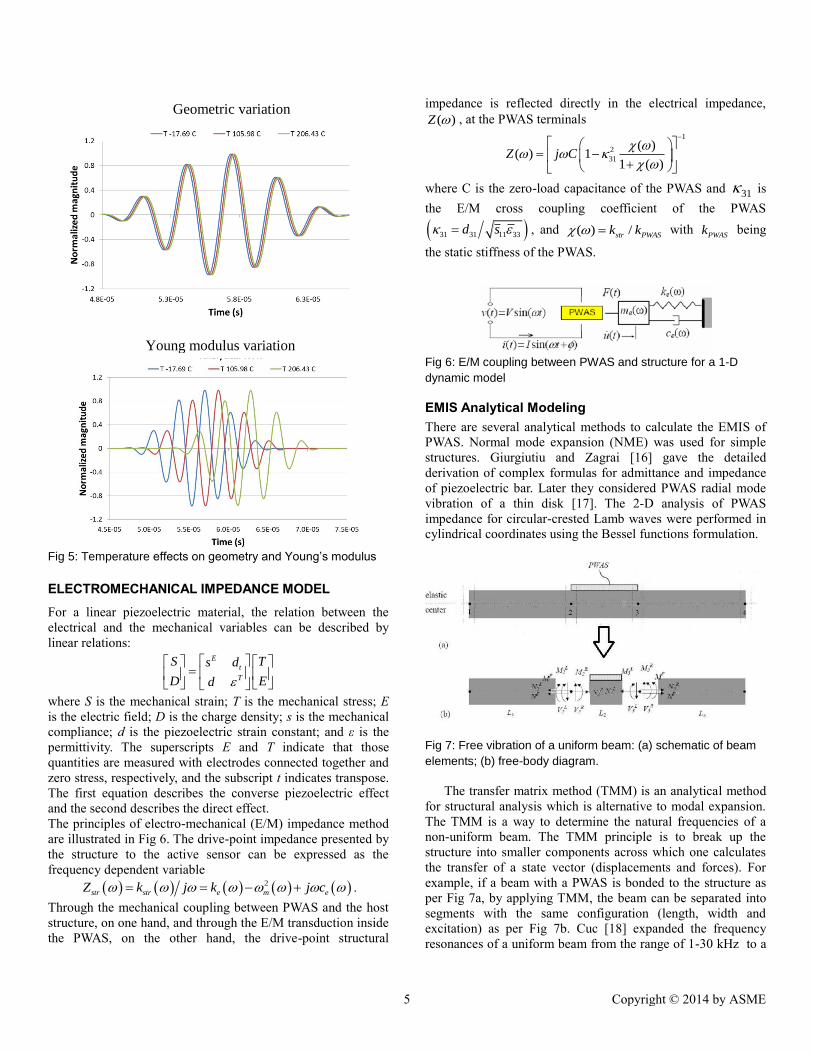
Fig 5: Temperature effects on geometry and Young’s modulus
ELECTROMECHANICAL IMPEDANCE MODEL For a linear piezoelectric material, the relation between the
electrical and the mechanical variables can be described by
linear relations: E
t
T
S Ts d
D Ed
where S is the mechanical strain; T is the mechanical stress; E
is the electric field; D is the charge density; s is the mechanical
compliance; d is the piezoelectric strain constant; and ε is the
permittivity. The superscripts E and T indicate that those
quantities are measured with electrodes connected together and
zero stress, respectively, and the subscript t indicates transpose.
The first equation describes the converse piezoelectric effect
and the second describes the direct effect.
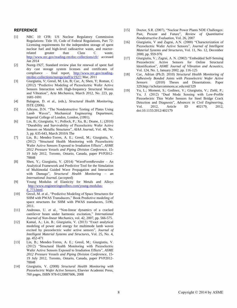
The principles of electro-mechanical (E/M) impedance method
are illustrated in Fig 6. The drive-point impedance presented by
the structure to the active sensor can be expressed as the
frequency dependent variable
2
str str e m eZ k j k j c .
Through the mechanical coupling between PWAS and the host
structure, on one hand, and through the E/M transduction inside
the PWAS, on the other hand, the drive-point structural
impedance is reflected directly in the electrical impedance,
( )Z , at the PWAS terminals
1
2
31
( )( ) 1
1 ( )Z j C
where C is the zero-load capacitance of the PWAS and 31 is
the E/M cross coupling coefficient of the PWAS
31 31 11 33d s , and ( ) /str PWASk k with PWASk being
the static stiffness of the PWAS.
Fig 6: E/M coupling between PWAS and structure for a 1-D
dynamic model
EMIS Analytical Modeling There are several analytical methods to calculate the EMIS of
PWAS. Normal mode expansion (NME) was used for simple
structures. Giurgiutiu and Zagrai [16] gave the detailed
derivation of complex formulas for admittance and impedance
of piezoelectric bar. Later they considered PWAS radial mode
vibration of a thin disk [17]. The 2-D analysis of PWAS
impedance for circular-crested Lamb waves were performed in
cylindrical coordinates using the Bessel functions formulation.
Fig 7: Free vibration of a uniform beam: (a) schematic of beam
elements; (b) free-body diagram.
The transfer matrix method (TMM) is an analytical method
for structural analysis which is alternative to modal expansion.
The TMM is a way to determine the natural frequencies of a
non-uniform beam. The TMM principle is to break up the
structure into smaller components across which one calculates
the transfer of a state vector (displacements and forces). For
example, if a beam with a PWAS is bonded to the structure as
per Fig 7a, by applying TMM, the beam can be separated into
segments with the same configuration (length, width and
excitation) as per Fig 7b. Cuc [18] expanded the frequency
resonances of a uniform beam from the range of 1-30 kHz to a
Geometric variation
Young modulus variation
5 Copyright © 2014 by ASME

higher frequency range 10-500 kHz and performed the
reliability and accuracy analysis of all available theoretical
models given experimental data for the uniform beam
specimen.
EMIS Finite Element Modeling A free PWAS has been modeled in order to have a fundamental
understanding of the multi-physics based modeling approach
and its efficiency using ANSYS multi-physics software with the
implicit solver in the frequency domain. To perform the
coupled-field analysis of PWAS transducers, we used coupled-
field elements, which could deal with both mechanical and
electrical fields. In the physics based coupled-field analysis of
piezoelectric materials, the stress field and the electric field are
coupled to each other such that change in one field will induce
change in the other field. The coupled-field finite elements used
in our analysis are the brick elements (SOLID5, SOLID226)
that have 8 or 20 nodes with up to six degrees of freedom
(DOF) at each node. When used for piezoelectric analysis, an
additional DOF, the electric voltage can be added in addition to
the displacement DOF’s. Reaction forces FX, FY, FZ
correspond to the X, Y, Z displacement DOF’s, respectively.
The electrical charge Q is the electrical reaction corresponding
to the voltage DOF. The charge Q is then used to calculate the
admittance and impedance data. The admittance Y is calculated
as I/V, where I is the current in ampere and V is the applied
potential voltage in volts. The current comes from the charge
accumulated on the PWAS surface electrodes and is calculated
as iI j Q with ω being the operating frequency, j is the
complex number and iQ is the summed nodal charge. In this
study, the PWAS was modeled using the 3D MP-FEM approach
with SOLID5 and SOLID226 elements. SOLID5 is a coupled-
field brick with eight nodes and up to six DOF per node while
SOLID226 has twenty nodes with up to four DOF per node. A
free square-shaped PWAS of dimension 7x7x0.2 mm3 was
modeled. The APC-850 material properties were assigned to the
PWAS as
97 49 49 0 0 0
49 97 44 0 0 0
49 49 84 0 0 0GPa
0 0 0 24 0 0
0 0 0 0 22 0
0 0 0 0 0 22
pC
8
947 0 0
0 605 0 10 F/m
0 0 947
p
2
0 0 0 0 12.84 0
0 0 0 12.84 0 0 C/m
8.02 8.02 18.31 0 0 0
pe
where [ ]pC is the stiffness matrix, [ ]p is the dielectric matrix
and [ ]pe is the piezoelectric matrix. The density of the PWAS
material is assumed to be 37600 /kg m .
Spectra from simulation and experiment of the free-PWAS
are sweeping from 1 to 1000 kHz are presented in Fig 8.
Globally, good matching is observed, but some slight
differences are visible especially for the third resonance around
~500 kHz. Small differences are expected in the numerical
response when compared to the experimental impedance
because the wiring was not modeled and unavoidable and
measuring errors may also occur. Nonetheless, this comparison
illustrates that good agreement can be obtained when MP-FEM
method is used, which is an important improvement over the
use of the conventional FEM method or the analytical models.
Fig 8: PWAS EMIS obtained from MP-FEM and measured from
HP4194 equipment, respectively.
POTENTIAL WORK ON ANALYTICAL MODEL
The implementation of SHM for DCSS and similar PVP
systems will require additional research and development as
well validation as an effective nondestructive testing (NDT)
and nondestructive evaluation (NDE) tool. As existing DCSS
systems continue to operate, some of them exceeding their
designed life span, new degradation processes are being found.
For these new degradation processes, the effectiveness of
existing inspection and NDE tools is unknown [15]. Many
inspections cannot be conducted effectively on a number of
materials and configurations. Potential radiation exposure and
obstructed areas also limit the inspectability of such systems.
Other conditions found in the field that may limit the
inspectability include surface condition in the inner and outer
diameters of weldments, access constraints, and tapers that
exist on components transitioning from one diameter to another.
For these reasons, new ways to assess the in-service state of
structures must be found. A potential approach is to use SHM
concepts and technologies that have been developed elsewhere
but may be quite applicable to PVP systems with appropriate
modifications.
6 Copyright © 2014 by ASME

The harsh environment associated with PVP systems will
challenge the use of many types of sensors due to high
temperature and/or gamma radiation stressors. For applications
to DCSS the development of appropriate sensors that can
tolerate initial cask loading temperatures and radiation levels
with minimal functional degradation is necessary. This can be
addressed through either the design or modification of materials
to increase resistance to the effects of radiation and temperature
or developing new materials or sensing schemes. The LAMSS
team at USC has begun testing PWAS systems under radiation
field [13]: Durability and survivability of PWAS transducers
were tested under gamma ray exposure. A Co-60 gamma source
was used to irradiate a set of PWAS transducers in an irradiator
with different exposure times. The dose rate and total absorbed
dose were calculated using Monte Carlo simulations (MCNPX
code). The PWAS material properties, electrical contact change
were characterized through a series of tests. The electro-
mechanical impedance spectrum of PWAS was measured. This
study provides a first step towards the fundamental
understanding of the PWAS irradiation survivability. Another
outcome of this study is to evaluate the potential of PWAS
transducers as irradiation sensors for nuclear applications.
After these preliminary results, we studied the effect of the
variations of the PWAS mechanical behavior, the dielectric
matrix, and the piezoelectric matrix in order to better
understand and to predict the effect of the radiation on these
different components using this multi-physics finite element
method. Three variability effects will be considered: (i) the
sensory system, (ii) the structural components, and (iii) the
nuclear environmental conditions (temperature and radiation).
The temperature and radiation effects will be examined through
parameter studies. Eventually, the analytical tools developed in
this subtask will permit fast and efficient evaluation of the
effect of variability on the structural sensing process.
(a) Sensory system variability considers the effects of
sensor aging and degradation. We will extend our
preliminary results to a full parametric study (size,
density, stiffness matrix, dielectric matrix,
piezoelectric matrix, etc.). The effects of variability in
PWAS positions on the structure and of impedance
coupling between PWAS and structure will also be
assessed.
(b) Structural variability includes the effect of slight
variations in material properties and/or the structural
geometry and tolerances. We will first determine
sensitivity of individual sensing methods. Then we
will introduce damage and repeat the variability study
to see if damage can still be detected in the presence of
structural variability.
(c) Environmental variability considers the effects of
temperature changes and radiation. We will superpose
these changes on the analytical models and determine
how much the structural sensing signals change is due
to these environment effects. We will establish the
sensitivity of various structural sensing methods to
environmental disturbances. Results from subtask 2.2
will be used to update the model parameters to further
study the environmental variability
SUMMARY AND CONCLUSIONS
SHM is a multidisciplinary process that involves several
disciplines that must be closely coordinated. Sensors are being
used to measure parameters such as temperature, pressure,
radiation levels, pH, and wall thickness or to indicate that
damage or failure in a system has already occurred (i.e.
detection of a leak). But through the implementation of SHM
approach the detection of materials degradation at relatively
early stages, before the damage occurs, can be potentially
achieved. Therefore, the development of active and passive
nondestructive evaluation methods based on SHM provides an
opportunity to progress the capability of monitoring DCSS and
similar PVP systems. The integration of SHM with existent
NDE tools in nuclear fields can increase the confidence of the
safe operation and provide assurance of in-service reliability.
Moreover, the development of SHM technologies can minimize
human intervention, decrease the cost associated with NPP
operation, and improve the reliability of essential systems by
continuously assessing the structural integrity of nuclear related
facilities. While SHM have been employed in different fields,
its applicability for PVP systems will require further
development and evaluation. This will required research to
address some of the challenges that were discussed. SHM
monitoring can provide decision makers, regulatory agencies,
and PVP system operators with timely information on the
health of the system. Ultimately, this information will result in
the reduction of operation and maintenance cost, and the timely
response can protect civilian population from catastrophic
system failure.
We address the fundamental issue of analytical modeling of
nuclear environmental effects in PWAS N-SHM system for
steel canister in DCSS in the present study. Some of the
challenges associated with the nuclear effects on DCSS system
are also discussed. We studied various nuclear effects on the
guided wave propagation as well as electromechanical
impedance through both analytical and finite element modeling.
We found that the temperature effect is principally due to the
modification of the elastic modulus, E, rather than the
geometrical expansion contraction. This preliminary work
provides the guidance for the development of PWAS based N-
SHM.
ACKNOWLEDGEMENT
The authors would like to acknowledge the financial support
from Department of Energy award DE-NE0000726 with
program manager Mr. Kenny Osborne.
7 Copyright © 2014 by ASME
REFERENCE [1] NRC 10 CFR: US Nuclear Regulatory Commission
Regulations: Title 10, Code of Federal Regulations, Part 72:
Licensing requirements for the independent storage of spent
nuclear fuel and high-level radioactive waste, and reactor-
related greater than Class C waste,
http://www.nrc.gov/reading-rm/doc-collections/cfr/ accessed
Jan 2014
[2] Nureg-1927, Standard review plan for renewal of spent fuel
dry cast storage system licenses and certificates of
compliance – final report, http://www.nrc.gov/reading-
rm/doc-collections/nuregs/staff/sr1927/ Mar, 2011
[3] Giurgiutiu, V; Gresil, M; Lin, B; Cuc, A; Shen, Y; Roman, C
(2012) “Predictive Modeling of Piezoelectric Wafer Active
Sensors Interaction with High-frequency Structural Waves
and Vibration”, Acta Mechanica, March 2012, No. 223, pp.
1681-1691
[4] Balageas, D. et al., (eds.), Structural Health Monitoring,
ISTE (2006).
[5] Alleyne, D.N. “The Nondestructive Testing of Plates Using
Lamb Waves”, Mechanical Engineering Department,
Imperial College of London, London, (1991).
[6] Lin, B.; Giurgiutiu, V.; Pollock, P.; Xu, B.; Doane, J.; (2010)
“Durability and Survivability of Piezoelectric Wafer Active
Sensors on Metallic Structures”, AIAA Journal, Vol. 48, No.
3, pp. 635-643, March 2010A The
[7] Lin, B.; Mendez-Torres, A. E.; Gresil, M.; Giurgiutiu, V.
(2012) “Structural Health Monitoring with Piezoelectric
Wafer Active Sensors Exposed to Irradiation Effects”, ASME
2012 Pressure Vessels and Piping Division Conference, 15-
19 July 2012, Toronto, Ontario, Canada, paper PVP2012-
78848
[8] Shen, Y.; Giurgiutiu, V. (2014) "WaveFormRevealer – An
Analytical Framework and Predictive Tool for the Simulation
of Multimodal Guided Wave Propagation and Interaction
with Damage”, Structural Health Monitoring – an
International Journal. (accepted)
[9] Young Modulus of Elasticity for Metals and Alloys
http://www.engineeringtoolbox.com/young-modulus-
d_773.html.
[10] Gresil, M. et al., “Predictive Modeling of Space Structures for
SHM with PWAS Transducers,” Book Predictive modeling of
space structures for SHM with PWAS transducers, 5190,
2011.
[11] Andreaus, U. et al., “Non-linear dynamics of a cracked
cantilever beam under harmonic excitation,” International
Journal of Non-linear Mechanics, vol. 42, 2007, pp. 566-575.
[12] Kamal, A.; Lin, B.; Giurgiutiu, V. (2013) “Exact analytical
modeling of power and energy for multimode lamb waves
excited by piezoelectric wafer active sensors”, Journal of
Intelligent Material Systems and Structures, Vol. 25, No. 4,
pp. 452-471
[13] Lin, B.; Mendez-Torres, A. E.; Gresil, M.; Giurgiutiu, V.
(2012) “Structural Health Monitoring with Piezoelectric
Wafer Active Sensors Exposed to Irradiation Effects”, ASME
2012 Pressure Vessels and Piping Division Conference, 15-
19 July 2012, Toronto, Ontario, Canada, paper PVP2012-
78848
[14] Giurgiutiu, V. (2008) Structural Health Monitoring with
Piezoelectric Wafer Active Sensors, Elsevier Academic Press,
760 pages, ISBN 978-0120887606, 2008
[15] Doctor, S.R. (2007), “Nuclear Power Plants NDE Challenges:
Past, Present and Future”, Review of Quantitative
Nondestructive Evaluation, Vol. 26, 2007
[16] Giurgiutiu, V and Zagrai, A.N. (2000) “Characterization of
Piezoelectric Wafer Active Sensors”, Journal of Intelligent
Material Systems and Structures, Vol. 11, No. 12, December
2000, pp. 959-976
[17] Giurgiutiu, V.; Zagrai, A. N. (2002) “Embedded Self-Sensing
Piezoelectric Active Sensors for Online Structural
Identification”, ASME Journal of Vibration and Acoustics,
Vol. 124, No. 1, January 2002, pp. 116-125
[18] Cuc, Adrian (Ph.D. 2010) Structural Health Monitoring of
Adhesively Bonded Joints with Piezoelectric Wafer Active
Sensors (2010) Theses and Dissertations. Paper
329.http://scholarcommons.sc.edu/etd/329
[19] Yu, L.; Momeni, S.; Godinez, V.; Giurgiutiu, V.; Ziehl, P.;
Yu, J. (2012) “Dual Mode Sensing with Low-Profile
Piezoelectric Thin Wafer Sensors for Steel Bridge Crack
Detection and Diagnosis”, Advances in Civil Engineering,
Vol. 2012, Article ID 402179, 2012,
doi:10.1155/2012/402179
8 Copyright © 2014 by ASME