analytical study of early kick detection and well control
TRANSCRIPT

Analytical Study of Early Kick Detection and WellControl Considerations for Casing while DrillingTechnologyM Azab ( [email protected] )
Case study
Keywords: Casing while Drilling, Conventional Drilling, Kick Tolerance, Early Kick Detection, Well Control
Posted Date: August 26th, 2021
DOI: https://doi.org/10.21203/rs.3.rs-845731/v1
License: This work is licensed under a Creative Commons Attribution 4.0 International License. Read Full License

1 | P a g e
Analytical Study of Early Kick Detection and Well
Control Considerations for Casing while Drilling
Technology
Said K. Elsayed
Faculty of Petroleum and mining Engineering, Suez University, [email protected]
Adel M. Salem
Faculty of Petroleum and mining Engineering, Suez University, [email protected]
Hany M. Azab
Faculty of Petroleum and mining Engineering, Suez University, [email protected]
Abstract
Recently, casing while drilling (CwD) technology has been employed to reduce drilling time
and expenses. These intelligent drilling technique improved wellbore stability, fracture
gradient, and formation damage while reducing exposure time but when a well control issue
arises, the differences in wellbore geometries and related volumes compared to regular
conventional drilling procedures necessitate a distinct strategy.
In this paper, the essential well control parameters were provided for casing while drilling
operations, presents simplified method that has been developed to evaluate the maximum kick
tolerance (KT) for both conventional and casing while drilling techniques using a mathematical
derivation, the narrow annular clearance, in contrast to drilling with a conventional drill string
would impair kick detection and handling operations. Furthermore, the large disparity in kick
tolerances should be carefully evaluated in order to avoid lost circulation/kick cycles as well
as examine and evaluate technical approaches to early kick detection (EKD) studying how they
relate to safety, efficiency, and reliability in a variety of common casing while drilling
operations.
According to preliminary findings, by utilizing casing while drilling technology and
compared to identical well was drilled conventionally using drill pipe, the annulus pressure
loss (APL) is average 3 times of the conventional drilling technique. Furthermore, kick
tolerance is reduced by 50% and maximum allowable well shut-in time reduced by 65%
necessitating early kick detection.
Keywords:
Casing while Drilling, Conventional Drilling, Kick Tolerance, Early Kick Detection, Well
Control

2 | P a g e
Introduction
As the industry evolves toward reservoirs that are deeper, more complicated, and more
expensive to develop, there is an increasing demand for technical solutions that enable
effective drilling and completions while lowering risks and costs to a minimum. Casing while
drilling (CwD) technologies mitigate drilling problems by providing capabilities that go
beyond the norm, allowing casing to achieve total depth (TD) efficiently, optimizing the well
architecture efficiently as shows in Figure 1. [1]
Furthermore, Casing while drilling may be best adapted solution to drill soft formations,
which are experienced at the top hole sections of the well and are concerned with various hole
problems. [2]
Figure 1: Conventional Drilling Vs Casing while Drilling
In Casing While Drilling operations, the casing is used as drill string, the required energy
(hydraulic and mechanical) is provided by the top drive system from the surface to the casing
string and its drill bit. A pilot bit, under-reamer, stabilizers, and drill lock assembly (DLA) are
typically included in a casing while drilling bottom hole assembly (BHA) as shows in Figure
2. DLA is a hydraulically sealed connection between the drilling assembly and the casing
strings Figure 3
For the surface and intermediate hole sections, an underreamer is utilised above the pilot bit
to open the hole to the final desired wellbore diameter. [3]
On the side of mud circulation, drilling fluid is pumped down the drill string and
circulated up through the annulus, just like in conventional drilling. This improvement in pipe

3 | P a g e
handling enhances well site safety while also allowing drillers to use regular rigs size or
smaller rigs designed expressly for casing drilling. [4]
Figure 2: Conventional drilling BHA Vs Casing while drilling BHA
Figure 3: Drill lock assembly
History of casing while drilling technology
Casing while drilling technology has been effectively used in a number of challenging wells
to drill through problematic well sections that would have been impossible to drill using
conventional drill pipe methods minimizing trip time and operational costs.
Since its initial field experiments in 1990 (Warren et al, 2001), CwD technology has evolved
to meet a variety of drilling problems and obstacles, to the point where it can drill from one
casing shoe to the next in a directional hole with a curve section. [5]
The first steps toward establishing this new method were taken in the 1890s, when engineers
studied a new strategy based on rotary drilling to drill a well with casing and then retrieve the

4 | P a g e
hydraulically expanded bit (Tessari & Madell, 1999). A further patent was presented a few
decades later, in 1926, which added a retrievable and re-runnable casing bit. [6]
In 2001, BP and Tesco recorded drilling surface and production casing intervals for 15 gas
wells in the Wamsutter area of Wyoming, USA, utilising casing while drilling technique. The
depths of these wells varied from 8200 feet to 9500 feet (Shepard et al. 2001). Shell Exploration
and Production Company significantly improved drilling efficiency in south Texas at the same
period by drilling underbalanced with casing, resulting in a cost decrease of about 30%.
(Fontenot et al. 2005). [7]
Different operators used casing to drill more than 2000 wellbore sections till 2005. More
than 1020 of these intervals were drilled vertically with casing and non-retrievable system,
approximately 620 intervals were drilled with partial liners, more than 400 intervals were
drilled vertically with a retrievable system, and about 12 intervals were drilled directionally
with a retrievable system. All of these early uses aided casing while drilling's evolution from
a novel technology with questionable reliability to a feasible solution that can save costs,
improve drilling productivity, and reduce rig downtime (Fontenot et al. 2005). [7]
Types of casing while drilling system
The casing is normally put into rotary motion and cemented in the well at the desired total
depth (TD), however there are now a variety of developed casing drilling types. As illustrated
in Figure 4, those models can be split into two types. [6]: -
1. Retrievable system
If the desired target depth is reached, the Bottom hole assembly (BHA) that is attached to the
first joint of the casing string with DLA can be retrieved using a wireline unit (wireline
retrievable system) or drill pipe.
2. Non-Retrievable system
BHA is not recovered in this system; if it is, it is cemented immediately after reaching the
necessary depth, and the bit is drilled out if the drilling procedure must be continued. Drillable
polycrystalline diamond compact (PDC) bits are a common bit utilised in this technique.

5 | P a g e
Figure 4: Retrievable and non-retrievable casing while drilling BHA (modified from Fontenot et al. 2005)
Features and benefits of casing while drilling technology
Despite the fact that there appear to be no significant differences between this technique and
the conventional drilling methods using a drill pipe as its backbone, the drilling operation using
casing tubulars has become one of our industry's most significant technological revolutions. [8]
CwD may save on rig equipment capital and operational costs by eliminating expenditures
involved with acquiring, handling, inspecting, shipping, and tripping the drill-string. [9]
According to researchers, CwD resulted in a 10% cost reduction and a 30% time savings
[(Lopez and Bonilla. 2010) and (Sánchez et al. 2012)]. Other studies [(Fontenot et al. 2003)
and (Karimi et al. 2011)] found that lost circulation was greatly decreased. In addition
[(Aadnoy et al. 2009) and (Radwan and Karimi. 2011)] have documented characteristics of
successful field implementation of CwD technology. As well as the suggestion that the fracture
gradient has improved (Salehi et al. 2013). [10]
The problem of reducing overall well costs while boosting output to maximise the return on
investment in well reserves is a major challenge for the oil and gas sector. This has been
accomplished to some extent by utilising casing while drilling technology as a solution or as
element of other mitigating requirements in drilling operations by: -
A. Reducing drilling time & increasing efficiency
Each foot drilled will be cased, making it a two-in-one procedure, allowing sections to
be completed faster (Figure 5) and if the casing becomes stuck before reaching the
planned setting depth, it can be set and cemented there. As it will be more efficient than
tripping out drill pipe out of hole with the possibility of fishing. Meanwhile, the

6 | P a g e
unreachable depth can be covered by a casing with a lower diameter that can be run
safely. [11]
Figure 5: Tesco’s CwD practices
B. Controlling casing strings cost
It's worth noting that the casing used in this approach is of the same grade and weight
as the casing used throughout conventional drilling. As a result, in case of casing while
drilling approach, there is no further or extra cost for a casing string to be used (Tessari
et al., 1999). [12]
C. Reducing cementing costs
The problem of reducing overall well costs while boosting output to maximise the
return on investment in well reserves is a major challenge for the oil and gas sector.
This has been accomplished to some extent by using casing while drilling as a solution
as the smaller annulus requires less cement and has less cement excess compared to
conventional drilling. [13]
D. Improving borehole cleaning efficiency.
CwD has a lower annular clearance between the casing and the borehole wall (Figure
6), resulting in enhanced annular velocity and borehole cleaning efficiency. As a result,
the likelihood of a stuck pipe is reduced. [13]

7 | P a g e
Figure 6: In casing while drilling, the annulus is narrower than in conventional drilling.
E. Improving wellbore stability
It may eliminate hole problems associated with tripping when the (BHA) needs to be
replaced or when the TD is reached, As most wellbore instability and stuck pipe
difficulties occur during tripping drill string in/out relates to non-productive time
(NPT). [14]
F. Reducing lost circulation
Casing while drilling helps to minimize mud loss into the formation. The Plastering
Effect produces a high-quality mud cake that seals the wellbore and prevents fluid
transfer between it and the formation wall. In the worst-case scenario, where the losses
are incurable, drilling will continue with minimal losses until the casing reaches the
proposed total depth. As a result, problems and dangers associated with swab, pit
volume monitoring, hole volumes, and fill up related to steel removed from the
wellbore in a lost circulation condition, such as hole collapse and stuck pipe, are no
longer a concern. [15]
Plastering/smearing effect
When the casing string rotates with limited annulus clearance, The casing contact
strengthens and enhances the wellbore's integrity, while the plastered filter cake
(Figure 7) decreases permeability at the wellbore zone, improving the fracture gradient
and allowing for a wider mud weight window, eliminating any possible loss circulation
(Figure 8) and well control events referring to “Plastering/Smearing Effect”. [16]

8 | P a g e
Figure 7: Plastering effect in casing while drilling operation from A to C (Karimi et al., 2011)
Figure 8: Plastering effect eliminate loss circulation
G. Rig Power Demand
Because of the reduced circulating pressure and elimination of periodic draw-works tripping,
the rig requires less horsepower and thus less maintenance and fuel cost. [17]
Well control for casing while drilling and problem statement
Well control is represented as a series of techniques for reducing a hydrocarbon wellbore's
"kick potential" and keeping it under control in the event of an unexpected flow of reservoir
fluids into the wellbore during drilling, completion, workover, or service activities. It entails
the use of procedures, techniques, processes, and equipment to ensure that field operations and
environment are safe. [18]
Today the oil and gas business grows, new and creative drilling technology are used to drill
oil wells in challenging environments. To deal with the kick of hydrocarbon fluids from the
formation in the well bore during drilling, every drilling technology requires a comprehensive
well control design which covered in this study.
Over 70% of kick events occur when tripping in/out of the hole, as is well reported. In CwD,
the string's bottom end is always in the bottom of the hole. As a result, when CwD is used, the
chances of kick events are reduced but still the study of allowable response time to a kick is a
vital part of this study. [3]
When CwD technique is used instead of conventional drilling method, a modification in
overall wellbore geometry (e.g. impact of Threaded, drill pipe sizes & Coupled connections in
wellbore geometry (Grijalva, 2017)) is seen in Figure 9, this condition is crucial for well
control-related methodologies and procedures. As a result, it's critical to understand the
distinctions between conventional drilling and CwD in terms of well control and its monitoring
system, As Blowout will occur if the well control system fails to early detect the kick

9 | P a g e
(formation pressure greater than wellbore pressure) and terminate it quickly and effectively.
[19]
Figure 9: (A) Conventional drilling, and (B) CwD wellbore geometry (Karimi et al. 2012).
There are many definitions have been given to describe kick tolerance (KT); however, for
practical purposes, kick tolerance can be defined as the largest kick volume that can be
tolerated without breaking the prior casing shoe. [20]
Regardless of which kick tolerance definition is used by an engineer during well design, a
common philosophy is that any design has an imaginary technical boundary around it, and that
making changes outside of this design boundary envelope risks related to well integrity and
operational safety during well planning. [21]
Furthermore, there is a risk of misrepresenting the significance of the unique combination
of historical events and effects. This is risky because just a 50 bbls kick did not result in a
blowout under particular conditions does not mean that a 5 bbls improperly handled under
identical conditions would not result in a disastrous blowout, and vice versa. In general, the
occurrence of one set of events and their consequences may or may not have an impact on
succeeding sets of events. These distinct combinations are often effected by kick tolerance
definition [21]
Recently, KT has been employed to determine casing setting depths during well design
making the drilling operation safer as the quantity of the kick volume that enters the well can
be determined by: the underbalance between mud weight and formation pressure; reservoir

10 | P a g e
properties (porosity & permeability); influx type (gas, oil or water); kick detection equipment
sensitivity and reliability; and well control crew reaction time. [22]
Effective early kick detection (EKD) and blowout prevention are among the most important
oilfield activities, as failure to do so can result in costly human, material, and financial losses,
as well as potential pollution. [23]
The necessity of quickly detecting and responding to a kick is commonly regarded in the
industry, and many businesses understand this keep track of a range of kick-related variables
(e.g., size of kicks taken, operations and its intensity)
The main Key Performance Indicators (KPIs) for kick safety that necessitate special
attention and regular monitoring [10]: -
1. Kick Detection Volume (KDV): How much influx volume happens before a kick is
positively detected?
2. Kick Response Time (KRT): How long does it take after a kick has been positively
detected before the influx is stopped by well-controlled procedures?
In any discipline of engineering, no design is created to accommodate systemic abuse. When
it comes to crew response time, awareness, and equipment reliability, the designer will have to
make some acceptable assumptions. He understands that crew preparation, training, and
competency must be proved prior to beginning on an operation. He may then justify the
variability in kick detection system performance and crew response time in statistical terms
after putting in place a framework of procedures to prevent gross errors. [24]

11 | P a g e
Approach
In this paper, the main objective and scope has been limited to the maximum allowable well
shut-in time as a measure of kick tolerance and influx flow rate, looking into well control
consideration in simulated vertical well that was drilled conventionally and using casing while
drilling technology. Using a single phase kick tolerance model, a water-based mud (WBM)
with a gas kick is considered to eliminate difficulties caused by gas solubility, evaluating the
maximum kick tolerance and allowable well shut-in time for each drilling technique.
Research methodology
When casing while drilling is utilized, the annular pressure loss is found high relative to
conventional drilling because the annulus between the borehole and the casing string is
relatively narrow (Figure 10), resulting in increased bottom hole pressure and reduced kick
tolerance.
Figure 10: Borehole wall clearance comparison between Casing while drilling (right) and conventional
drilling (left).
Because of its consequences in well design, drilling, and well control, kick tolerance has
lately gained in importance in well operations. This article aims to expand understanding about
Kick Tolerance and serves as a technical foundation for casing while drilling by investigating
a simple method for applying the kick tolerance idea in an effective way based on field data.
EKD is one of the most critical areas for well control safety enhancement. As more
operations are undertaken in casing while drilling operations, the requirement for earlier, more
effective, and more dependable kick detection across a wide variety of drilling operations has
really become increasingly crucial. [22]
In well control planning process, allowable well shut-in time is one of the key parameters
in well control considerations during drilling operations. The methodology given in this article

12 | P a g e
comprises the use of gas flow deterministic models combined with maximum kick tolerance
to investigate the likelihood of the undesired well flow during deploying casing while drilling
operations.
Mathematical Derivation of kick tolerance and allowable well shut-in time
Kick tolerance mathematical model for a theoretical well drilled with casing can be seen in
this practical section. Calculations such as annular pressure loss, bottomhole pressure, kick
height, kick tolerance and allowable well shut-in time based on influx flow rate and compared
to conventional drilling method.
In present work, the kick tolerance model is developed with following assumptions:
1. Gas compressibility factor “Z” = 1
2. Single phase kick tolerance model
3. Poisson ratio (Ѵ) = 0.4
4. Overburden stress gradient (σ) = 1psi/ft 5. Gas compressibility factor “Z” = 1
6. Drillpipe OD = 5 inch
Following the model assumptions, a simplified Mathematical Derivation method is
developed and presented in the following section: -
1. Calculate drilling fluid hydrostatic pressure (HP) at kick depth (TVDkick) using
Equation.1 𝐻𝐻𝐻𝐻 = 0.052 ∗ 𝜌𝜌𝜌𝜌𝜌𝜌𝜌𝜌 ∗ 𝑇𝑇𝑇𝑇𝑇𝑇𝑘𝑘𝑘𝑘𝑘𝑘𝑘𝑘 𝐸𝐸𝐸𝐸. 1
2. According to annular velocity, mud rheology and drill string configuration, determine
Annular Pressure Loss (APL) at kick depth (TVDkick) using Equation.2
𝐴𝐴𝐻𝐻𝐴𝐴 = (1.4327 ∗ 10−7 ) ∗ 𝜌𝜌𝜌𝜌𝜌𝜌𝜌𝜌 ∗ 𝑇𝑇𝑇𝑇𝑇𝑇𝑘𝑘𝑘𝑘𝑘𝑘𝑘𝑘 ∗ 𝐴𝐴𝑇𝑇2𝑇𝑇ℎ𝑜𝑜𝑜𝑜𝑜𝑜 − 𝑇𝑇𝐷𝐷𝑘𝑘𝐷𝐷𝑜𝑜 𝐸𝐸𝐸𝐸. 2
3. Based on APL value, calculate bottom hole pressure (BHP) using Equation.3
𝐵𝐵𝐻𝐻𝐻𝐻 = 𝐻𝐻𝐻𝐻 + 𝐴𝐴𝐻𝐻𝐴𝐴 𝐸𝐸𝐸𝐸. 3
4. For a kick depth (TVDkick), find formation pressure (FP) using Equation.4
𝐻𝐻𝑃𝑃 = 𝐹𝐹𝐻𝐻𝐹𝐹 ∗ 𝑇𝑇𝑇𝑇𝑇𝑇𝑘𝑘𝑘𝑘𝑘𝑘𝑘𝑘 𝐸𝐸𝐸𝐸. 4
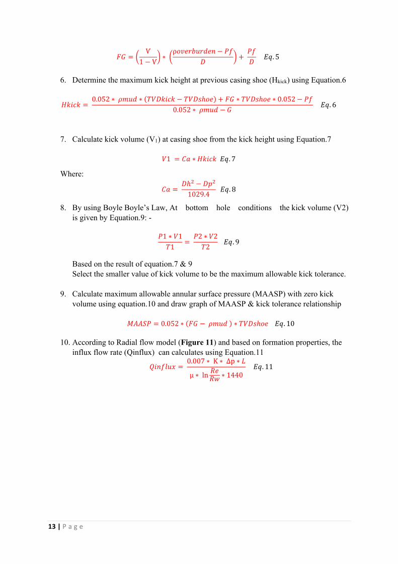
5. Calculate formation fracture gradient (FG) at previous casing shoe by using Hubbert
and Willis method Equation.5
13 | P a g e
𝐹𝐹𝐹𝐹 = � Ѵ1−Ѵ� ∗ �ρ𝑜𝑜𝑜𝑜𝑜𝑜𝑜𝑜𝑜𝑜𝜌𝜌𝑜𝑜𝜌𝜌𝑜𝑜𝑜𝑜 − 𝐻𝐻𝑃𝑃𝑇𝑇 �+
𝐻𝐻𝑃𝑃𝑇𝑇 𝐸𝐸𝐸𝐸. 5
6. Determine the maximum kick height at previous casing shoe (Hkick) using Equation.6
𝐻𝐻𝑘𝑘𝑘𝑘𝑘𝑘𝑘𝑘 = 0.052 ∗ 𝜌𝜌𝜌𝜌𝜌𝜌𝜌𝜌 ∗ (𝑇𝑇𝑇𝑇𝑇𝑇𝑘𝑘𝑘𝑘𝑘𝑘𝑘𝑘 − 𝑇𝑇𝑇𝑇𝑇𝑇𝑠𝑠ℎ𝑜𝑜𝑜𝑜) + 𝐹𝐹𝐹𝐹 ∗ 𝑇𝑇𝑇𝑇𝑇𝑇𝑠𝑠ℎ𝑜𝑜𝑜𝑜 ∗ 0.052− 𝐻𝐻𝑃𝑃
0.052 ∗ 𝜌𝜌𝜌𝜌𝜌𝜌𝜌𝜌 − 𝐹𝐹 𝐸𝐸𝐸𝐸. 6
7. Calculate kick volume (V1) at casing shoe from the kick height using Equation.7
𝑇𝑇1 = 𝐶𝐶𝐶𝐶 ∗ 𝐻𝐻𝑘𝑘𝑘𝑘𝑘𝑘𝑘𝑘 𝐸𝐸𝐸𝐸. 7
Where: 𝐶𝐶𝐶𝐶 = 𝑇𝑇ℎ2 − 𝑇𝑇𝐷𝐷2
1029.4 𝐸𝐸𝐸𝐸. 8
8. By using Boyle Boyle’s Law, At bottom hole conditions the kick volume (V2)
is given by Equation.9: -
𝐻𝐻1 ∗ 𝑇𝑇1𝑇𝑇1= 𝐻𝐻2 ∗ 𝑇𝑇2𝑇𝑇2
𝐸𝐸𝐸𝐸. 9
Based on the result of equation.7 & 9
Select the smaller value of kick volume to be the maximum allowable kick tolerance.
9. Calculate maximum allowable annular surface pressure (MAASP) with zero kick
volume using equation.10 and draw graph of MAASP & kick tolerance relationship
𝑀𝑀𝐴𝐴𝐴𝐴𝑀𝑀𝐻𝐻 = 0.052 ∗ (𝐹𝐹𝐹𝐹 − 𝜌𝜌𝜌𝜌𝜌𝜌𝜌𝜌 ) ∗ 𝑇𝑇𝑇𝑇𝑇𝑇𝑠𝑠ℎ𝑜𝑜𝑜𝑜 𝐸𝐸𝐸𝐸. 10
10. According to Radial flow model (Figure 11) and based on formation properties, the
influx flow rate (Qinflux) can calculates using Equation.11 𝑄𝑄𝑘𝑘𝑜𝑜𝑃𝑃𝑜𝑜𝜌𝜌𝑄𝑄 = 0.007 ∗ K ∗ Δp ∗ 𝐴𝐴µ ∗ ln
𝑅𝑅𝑜𝑜𝑅𝑅𝑅𝑅 ∗ 1440 𝐸𝐸𝐸𝐸. 11

14 | P a g e
Figure 11: Radial flow model
11. Based on influx flow rate (Qinflux ) and After kick tolerance is determined, 5 bbl.
because of pit gain alarm setting and 1 bbl. because of safety reasons have to be
subtracted from it. the estimated shut-in time limit can be calculated using
Equation.12 𝑀𝑀𝐶𝐶𝑄𝑄𝑘𝑘𝜌𝜌𝜌𝜌𝜌𝜌 𝐴𝐴𝑜𝑜𝑜𝑜𝑜𝑜𝑅𝑅𝐶𝐶𝑜𝑜𝑜𝑜𝑜𝑜 𝑊𝑊𝑜𝑜𝑜𝑜𝑜𝑜 𝑀𝑀ℎ𝜌𝜌𝑢𝑢 𝑘𝑘𝑜𝑜 𝑇𝑇𝑘𝑘𝜌𝜌𝑜𝑜 = 𝑀𝑀𝐶𝐶𝑄𝑄𝑘𝑘𝜌𝜌𝜌𝜌𝜌𝜌 𝐴𝐴𝑜𝑜𝑜𝑜𝑜𝑜𝑅𝑅𝐶𝐶𝑜𝑜𝑜𝑜𝑜𝑜 𝐾𝐾𝑘𝑘𝑘𝑘𝑘𝑘 𝑇𝑇𝑜𝑜𝑜𝑜𝑜𝑜𝑜𝑜𝐶𝐶𝑜𝑜𝑘𝑘𝑜𝑜 𝑄𝑄𝑘𝑘𝑜𝑜𝑃𝑃𝑜𝑜𝜌𝜌𝑄𝑄 𝐸𝐸𝐸𝐸. 12
Field case study
The well studied in this paper (Well X-2) was planned as a replacement for Well X-1, which
was 50 metres away from the surface location of the offset well X-1, Well X-1 had been
plugged and abandoned due to a wellbore instability and stuck pipe problems in the
intermediate section.
It is sometimes impossible to run the casing through these problematic hole sections,
resulting in significant time loss. To achieve successful operations, timely reaming trips are
required during drilling and prior to running casing.
To limit the risk of unplanned occurrences of drilling problems in this area, many methods
were used, including: -
• Modifying the mud's physical properties,
• Performing several short trips to combat openhole drag forces, and
• Running reaming-while-drilling assembly to ensure a smooth hole condition before
running casing to the bottom.
Unfortunately, these methods would increase the likelihood of fishing jobs while having a
negative impact on drilling performance and rig downtime.

15 | P a g e
After performing multiple attempts to pull out the drillstring without success with severe
pack-offs while tripping out , the drilling engineering team decided to deploy Casing while
Drilling (CwD) technology in Well X-2 As it has been used successfully in many places to
reduce potential non-productive time (NPT), enhance drilling performance and limit
unplanned events related to conventional drilling method.
However, this procedure necessitates a precise assessment of the control conditions as well
as the hole instability problem, which Casing While Drilling will address. The following
description highlights the operational conditions and well control for the considered hole
sections when drilled conventionally and utilizing casing while drilling methods.
Planning and Preparation
During the design stage of this well, a multi-disciplinary technical team analysed two runs
utilising conventional and CwD techniques to evaluate comparative kick tolerance and assess
allowable well shut-in time to reach casing point with appropriate well control tracking system
as they predicted a high formation pressure at 2145 ft TVD (TVDkick) with a well control risk.
Both technical runs required a thorough planning stage in which the operator and major
service companies examined and debated hazard analyses, contingency plans, procedures, and
BHA design. The first objective of the project was to demonstrate the CwD technology's
reliability in the view of well control and risk mitigation. This goal will be seen in the following
sections.
BHA design, optimum drilling practises, drilling parameters, torque and drag modelling,
hydraulics, well control equipment considerations, rig specifications, BHA retrieving and
setting operations procedures, logging and cementing were all considered during this planning
stage. The involvement of all stakeholders involved in the planning process to ensure the
success of the applications of CwD without any well control risk.
Drilling Program
By using standard rotary BHA, Well X-2 was identified and regularly drilled with a standard
wellbore architecture (see Figure 12) in four phases: 26-in, 17 ½-in, 12 ¼-in and 8 ½-in.
After the 20-inch shoe had been drilled out the conventionally, the 17 ½-in surface phase
was successfully vertical drilled with large diameter bit (17-1/2 in roller cone bit) with no well
control system, cased with 13-3/8 in. 72# L80 BTC surface casing at 484 ft.
The next section is typically planned to be drilled with 12-1/4 in PDC bit and to be cased
with 9-5/8 in intermediate casing. With an anticipated wellbore instability problem, the

16 | P a g e
intermediate sections should be designed utilizing CwD technique to set 9-5/8 in casing, 23#
L80 BTC at 2611 ft, as shown in Figure 12.
Table 1: Casing configuration
Casing Size
(in)
Casing Weight
(ppf)
Casing Grade
Setting Depth
(ft)
20 94 K55 79
13 3/8 72 L80 484
9 5/8 36 J55 2611
7 23 L80 5842

17 | P a g e
Figure 12: Well schematic
18 | P a g e
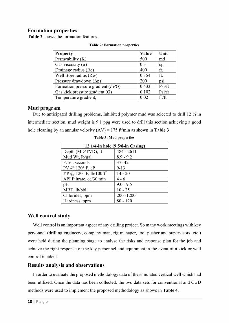
Formation properties
Table 2 shows the formation features.
Table 2: Formation properties
Property Value Unit
Permeability (K) 500 md
Gas viscosity (µ) 0.3 cp
Drainage radius (Re) 400 ft.
Well Bore radius (Rw) 0.354 ft.
Pressure drawdown (Δp) 200 psi
Formation pressure gradient (FPG) 0.433 Psi/ft
Gas kick pressure gradient (G) 0.102 Psi/ft
Temperature gradient, 0.02 f°/ft
Mud program Due to anticipated drilling problems, Inhibited polymer mud was selected to drill 12 ¼ in
intermediate section, mud weight is 9.1 ppg were used to drill this section achieving a good
hole cleaning by an annular velocity (AV) = 175 ft/min as shown in Table 3
Table 3: Mud properties
12 1/4-in hole (9 5/8-in Casing) Depth (MD/TVD), ft 484 - 2611
Mud Wt, lb/gal 8.9 - 9.2
F. V., seconds 37- 42
PV @ 120° F, cP 9-13
YP @ 120° F, lb/100ft2 14 - 20
API Filtrate, cc/30 min 4 - 6
pH 9.0 - 9.5
MBT, lb/bbl 10 - 25
Chlorides, ppm 200 -1200
Hardness, ppm 80 - 120
Well control study
Well control is an important aspect of any drilling project. So many work meetings with key
personnel (drilling engineers, company man, rig manager, tool pusher and supervisors, etc.)
were held during the planning stage to analyse the risks and response plan for the job and
achieve the right response of the key personnel and equipment in the event of a kick or well
control incident.
Results analysis and observations
In order to evaluate the proposed methodology data of the simulated vertical well which had
been utilized. Once the data has been collected, the two data sets for conventional and CwD
methods were used to implement the proposed methodology as shows in Table 4.

19 | P a g e
Table 4: Study results
Output Data Unit Conventional Drilling Method CwD Method
Hydrostatic Pressure (HP) psi 1015 1015
Annular Pressure Loss (APL) psi 11.4 32.6
Bottom Hole Pressure (BHP) psi 1026.4 1047.6
Formation Pressure (FP) psi 928.8 928.8
Fracture Gradient (FG) ppg 15.6 15.6
Kick Height (Hkick) ft 673 673
Kick Tolerance (KT) bbl 36.6 16.8
Maximum Allowable Surface
Pressure (MAASP) psi 163.6 163.6
Kick inflow rate (Qinflux) bbl/min 4.6 4.6
Allowable Well Shut-in Time
with 20 ft drilled into
overpressured formation
minute 6.6 2.3
It is vital to fully comprehend the impacts of kick tolerance in the application of casing
while drilling in order to provide a safe drilling operations by reducing the danger of
unscheduled influx from the formation. Furthermore, because a hypothetical formation
breakup can result in circulation losses and a kick event, this value is critical for the reliable
execution of well control procedures.
To avoid kick, we must keep the bottom hole pressure higher than the formation pore
pressure. To do so, and for planning purposes, it is necessary to develop a kick tolerance graph
for each section, as illustrated in Figure13. the kick volume is plotted on the X-axis, and the
MAASP is plotted on the Y-axis in that figure. The greatest MAASP determined using
Equation 10 is 163.8 psi. For zero maximum allowable surface pressure, is the maximum kick
volume as calculated by Equations 8 & 9, the kick tolerance graph is the straight line that
connects points 1 and 2.

20 | P a g e
Figure 13: Comparison between Conventional & Casing while drilling method
In terms of well control, the main differences between CwD and conventional drilling are
kick tolerance and maximum allowable well shut-in time. Based on Figure 14, the maximum
allowable kick volume at the bottomhole for a conventionally drilled 12-1/4” hole section at
2145 ft is 36.6 bbl., compared to 16.8 bbl. for a CwD drilled section. As a result, the maximum
allowable kick tolerance for sections drilled with CwD is only 45.90 % of what would be
allowed with conventional drill pipe. As early detection of the kick is critical to a successful
well control strategy, it is suggested that the pit gain level alarm be set to the lowest possible
value.

21 | P a g e
Figure 14: Results analysis
Furthermore, because of the reduced annular capacity, if the kick is gas, the bubble will
expand quicker in terms of height, resulting in extremely high surface casing pressures and a
reduced MAASP value.
As result of high APL in CwD, pump adjustments should be made to keep
constant bottomhole pressure during well control operations.
Another key conclusion is the length of overpressures formation drilled before kick is
detected must be taken into account during careful planning as show in Table 5, Because the
annulus of a CwD well is so narrow compared to a conventional well, even a small change in
influx volume can result in a huge difference in allowable Blowout preventer (BOP) closing
time and well control procedure.
Table 5: Drilled length into overpressures formation vs allowable well shut-in time
Length drilled
(ft)
Kick inflow rate
Qinflux
(bbl/min)
Maximum allowable well shut-in time
minute
Conventional method CwD method
1.00 0.23 132.8 46.9
2.00 0.46 66.4 23.4
3.00 0.69 44.3 15.6
4.00 0.92 33.2 11.7
5.00 1.15 26.6 9.4
6.00 1.38 22.1 7.8
7.00 1.61 19.0 6.7

22 | P a g e
8.00 1.84 16.6 5.9
9.00 2.07 14.8 5.2
10.00 2.30 13.3 4.7
11.00 2.54 12.1 4.3
12.00 2.77 11.1 3.9
13.00 3.00 10.2 3.6
14.00 3.23 9.5 3.3
15.00 3.46 8.9 3.1
16.00 3.69 8.3 2.9
17.00 3.92 7.8 2.8
18.00 4.15 7.4 2.6
19.00 4.38 7.0 2.5
20.00 4.61 6.6 2.3
For example, if 20 feet of overpressured formation is drilled in a CwD scenario, considering
the kick inflow rate is 4.6 bbl/min and the pit level was set at +/- 5 bbls and after the pit level
alert, there are just 2.3 minutes to shut-in the well with maximum 16.8 bbls kick volume
(Figure15), which is insufficient. In such circumstances, it is suggested that the prior casing
shoe be set deeper.
Figure 15: Kick volume vs allowable well shut-in time

23 | P a g e
Conclusion and recommendation
In order to meet the need of the oil and gas industry for innovative drilling technology this
research study has been conducted to perform the necessary analysis and develop a
methodology for presenting the importance of early kick detection in casing while drilling
operations.
• The primary goal of casing while drilling technology is to assist in driving the casing
as deep as possible in order to close the troublesome zone. To achieve this goal,
numerous operational and engineering tasks were required to assure that this system
could be used.
• From the well control side of view, narrow annular clearance and varied pipe
geometries that are distinct from drilling with drill pipe would result influx height
longer than conventional drilling method creating higher choke and casing shoe
pressures as the kick reaches the surface earlier.
• The introduced kick tolerance calculation assumes a volume of gas that has already
entered the wellbore has risen to the casing shoe depth, to avoid casing shoe breaking,
the volume of the influx should be established (weakest point in wellbore). However,
necessitate modifications to earlier well control systems in order to use CwD
technology.
• The study's findings revealed a considerable reduction in kick tolerance and allowable
well shut-in time for CwD technique and according to this analytical study, with more
well control considerations related to kick tolerance and choosing appropriate early
kick detection instruments, a complete engineering analysis must be performed during
the initial start-up and design phase that more performance enhancement and well
control optimization can be obtained.
• In order to assess the management of well control events and enhance drilling
performance, the well control condition, such as unwanted formation influx events,
maximum kick tolerance of the formations and allowable well shut-in time, must be
evaluated in any given well. And choosing appropriate early kick detection instruments
during the initial start-up and design phase to result more performance enhancement
and well control optimization.
• Demonstrate the technology's efficacy in reducing the dangers associated with
traditional drilling, which might easily result in the well being lost and further
unplanned sidetracks

24 | P a g e
• By implication, the kick detection capabilities of rig equipment and employees, as well
as the competency of rig operating staff to handle well-control events using best
practises, are the main points of considerable attention in this approach.
• The findings of this study imply that there is still a window of opportunity for
improving casing while drilling technology by addressing well control throughout the
design phase
• It is possible to export the kick tolerance estimations and associated probability derived
in this study to another operating business. The outcomes are different from the
reservoir engineering and drilling engineering in which the historical records were
created, nevertheless, the techniques of this methodology can be used in any established
framework on their own. A key assumption in all circumstances is that well
control incidents may be successfully managed in a consistent manner using verifiable
effectiveness in terms of well control equipment reliability, efficiency, and staff
competency.

25 | P a g e
Nomenclature
Abbreviations
CwD Casing while Drilling
EKD Early Kick Detection
KT Kick Tolerance, bbl
APL Annular Pressure Loss, psi
TD Total Depth, ft
DLA Drill Lock Assembly
BHA Bottom Hole Assembly
PDC Polycrystalline Diamond Compact
NPT Non-Productive Time
KPI Key Performance Indicators
KDV Kick Detection Volume, bbl
KRT Kick Response Time, min
WBM Water Based Mud
BOP Blowout Preventer
Symbols
Z Gas Compressibility Factor
HP Hydrostatic Pressure, psi
TVDkick kick True Vertical Depth, ft
ρmud Mud Weight, ppg
AV Annular Velocity, ft/min
Dhole Hole Diameter, in
Dpipe Drill Pipe Outside Diameter, in
Dcasing Casing Outside Diameter, in
BHP Bottomhole Pressure, psi
FP Formation Pressure, psi
FPG Formation Pressure Gradient, psi/ft
Ѵ Poisson ratio
ρoverburden Overburden Stress Gradient, psi/ft
D True Vertical Depth of Weakest Point in Open Hole Section, ft
TVDshoe True Vertical Depth of Casing Shoe, ft
G Gas kick pressure gradient, psi/ft
Hkick Kick Height, ft
Ca Annular Capacity, bbl/ft
Dh Hole Diameter, in
Dp Drillpipe Diameter, in
P1 Fracture pressure at shoe, psi
T1 Temperature at shoe, F°
P2 Formation pressure at the kick zone, psi

26 | P a g e
T2 Temperature at kick zone, F°
MAASP Maximum Allowable Annular Surface Pressure, psi
Qinflux Influx Flow Rate, bbl/min
K Permeability, md
ΔP Differential Pressure, psi
L length of drilled section in overbalanced formation, ft
µ Gas viscosity, cp
Re Radius of drainage, ft
Rw Radius of wellbore, ft
27 | P a g e
References
1. Gupta, A.K.: "Drilling with Casing: Prospects and Limitations" SPE Western
Regional/AAPG Pacific Section/GSA Cordilleran Section Joint Meeting, Anchorage,
Alaska, SPE 99536. May 8-10, 2006.
https://doi.org/10.2118/99536-MS
2. M.M. Hossain; M.M. Amro. “Prospects of Casing While Drilling and the Factors to be
Considered During Drilling Operations in Arabian Region” IADC/SPE Asia Pacific
Drilling Technology Conference and Exhibition, Kuala Lumpur, Malaysia, SPE-
87987-MS, September 13–15, 2004.
https://doi.org/10.2118/87987-MS
3. Fontenot. Highnote, J., Warren, T., and Houtchens, B., “Casing Drilling Activity Expands
in South Texas” SPE/IADC Drilling Conference, Amsterdam, SPE-79862, Feb 19-21,
2003.
https://doi.org/10.2118/79862-MS
4. Tommy M. Warren; Per Angman; Bruce Houtchens.: "Casing Drilling Application Design
Considerations". IADC/SPE Drilling Conference, New Orleans, Louisiana, February
2000. SPE-59179-MS.
https://doi.org/10.2118/59179-MS
5. Abubakar, M., Chika, J. O. and Ikebudu, A. O. "Current Trends and Future Development
in Casing Drilling" International Journal of Science and Technology, 2(8), pp. 567-582,
2012
https://www.researchgate.net/publication/266885316
6. B. Marbun, Y. Adinugratama, Bramantyo E. Kurnianto. "Feasibility Study of Casing
While Drilling Application on Geothermal Drilling Operation" Thirty-Ninth
Workshop on Geothermal Reservoir Engineering Stanford University, Stanford,
California, February 24-26, 2014.
https://pangea.stanford.edu/ERE/pdf/IGAstandard/SGW/2014/Marbun2.pdf
7. Pavković Bojan1, Bizjak Renato1, Petrović Bojan. "Review of Casing while Drilling
Technology". Underground Mining Engineering 29, University of Belgrade – Faculty
of Mining and Geology, December 10, 2016

28 | P a g e
8. O. Grijalva; J.. Holzmann; J. Oppelt; N. Perozo; C. Paz; A. Asgharzadeh. "OCTG
Advancements in Casing Drilling: Where We Have Been and Where Are We Going?"
SPE Oklahoma City Oil and Gas Symposium, SPE-185102-MS. March 27–31, 2017.
https://doi.org/10.2118/185102-MS.
9. Yash Gupta; Sudeepto Nilmani Banerjee. "The application of expandable tubulars in casing
while Drilling". SPE Production and Operations Symposium, Richardson, Texas,
March-31 April-3, 2007.
https://doi.org/10.2118/105517-MS
10. Brian Tost, Kelly Rose, Fred Aminzadeh, Magdalene A. Ante, Nicolas Huerta. "Kick
Detection at the Bit: Early Detection via Low Cost Monitoring". National Energy
Technology Laboratory, 1450 Queen Avenue SW, Albany, OR 97321. 7 June 2016.
https://www.osti.gov/servlets/purl/1327810/
11. Bonar Noviasta; Hanafi Muhamad Falhum; Budi Setiawan. "Innovative Casing Drilling
Technology Improved the Ability to Set the Casing Deeper Through the Problematic
Zone in Indonesia Geothermal Operation". Abu Dhabi International Petroleum
Exhibition & Conference. SPE-188960-MS. November 13–16, 2017.
https://doi.org/10.2118/188960-MS
12. Dipal Patel, Manan Shah, Vivek Thakar, Anirbid Sircar. "Identifying Casing While Drilling
(CwD) Potential in Geothermal Scenario Along with Economics". 44th Workshop on
Geothermal Reservoir Engineering Stanford University, Stanford, California, February
11-13, 2019.
https://pangea.stanford.edu/ERE/pdf/IGAstandard/SGW/2019/Patel.pdf
13. Ossama Sehsah; Amir El Kawass; Syed Muhamad Siddik; Ahmed Refai; Syed Zahoor
Ullah; Abdulqawi Al Fakih; Jeremy Halma; Ahmed Aboul Enein; Mohammed Sami
Almomen; Ahmed Subhi Alatiyyah. "Casing While Drilling Transformation into
Standard Operation in Middle East". International Petroleum Technology Conference.
Dhahran, Kingdom of Saudi Arabia. January 13–15, 2020. IPTC-19730-MS.
https://doi.org/10.2523/IPTC-19730-MS
14. A. Kerunwa1, C. I. C. Anyadiegwu. "Overview of the advances in casing drilling
technology". Petroleum & Coal 57(6) 661-675, 2015
15. Moji Karimi; Scott Petrie; Eric Moellendick; Calvin Holt. “A Review of Casing Drilling
Advantages to Reduce Lost Circulation, Improve Wellbore Stability, Augment
Wellbore Strengthening, and Mitigate Drilling-Induced Formation Damage”

29 | P a g e
SPE/IADC Middle East Drilling Technology Conference and Exhibition.. Muscat,
Oman. SPE-148564-MS, October 24–26, 2011.
https://doi.org/10.2118/148564-MS
16. Bonar T. H. Marbun, Widiyanto, Yudhistira Adinugratama, and Bramantyo E. Kurnianto.
"Feasibility Study of Casing While Drilling Application on Geothermal Drilling
Operation". Thirty-Ninth Workshop on Geothermal Reservoir Engineering Stanford
University, Stanford, California, February 24-26, 2014.
https://www.semanticscholar.org/paper/Feasibility-Study-of-Casing-While-Drilling-
on-Marbun-Adinugratama/b2a8c8cc5d812a3c79c02b88453dc19417aa2498
17. E.. Beaumont; L.. de Crevoisier; F.. Baquero; J.. Sanguino; D.. Herrera; E.. Cordero. “First
Retrievable Directional Casing While Drilling (DCwD) Application in Peruvian Fields
Generates Time Reduction and Improves Drilling Performance Preventing Potential
Non-Planned Downtime” SPE Latin American and Caribbean Petroleum Engineering
Conference, Lima, Peru, SPE-139339-MS. December 1–3, 2010.
https://doi.org/10.2118/139339-MS
18. O. Grijalva Meza, K.. Kamp, A.. Asgharzadeh, O.. Bello, R.. Freifer, J.. Oppelt. "Well
Control for Drilling with Casing: Theoretical and Experimental Insights into Hydraulic
Behavior in Small Annular Clearances". SPE/IADC Middle East Drilling Technology
Conference and Exhibition, SPE-189366-MS. January 29–31, 2018.
https://doi.org/10.2118/189366-MS
19. Dipal Patel, Vivek R Thakar, Sivakumar Pandian, Manan Shah, Anirbid Sircar. "A review
on casing while drilling technology for oil and gas production with well control model
and economical analysis". Petroleum. December 2018. Volume 5, Issue 1, March
2019, Pages 1-12.
https://www.researchgate.net/publication/329598671
20. Carolina Silva Avelar, Paulo Roberto Ribeiro. "The study of well planning using the kick
tolerance concept" 18th International Congress of Mechanical Engineering. November
6-11, 2005.
https://www.abcm.org.br/anais/cobem/2005/PDF/COBEM2005-2487.pdf
21. Adetola D. Dedenuola; Isaac E. Iyamu; Olayinka A. Adeleye. “Stochastic Approach to
Kick Tolerance Determination in Risk Based Designs” SPE Annual Technical
Conference and Exhibition, Denver, Colorado, SPE-84174-MS. October 5–8, 2003,
https://doi.org/10.2118/84174-MS

30 | P a g e
22. Nagham Jasim Al-Ameri. "Kick tolerance control during well drilling in southern Iraqi
deep wells", Iraqi Journal of Chemical and Petroleum Engineering, Vol.16 No.3,
September 2015
https://www.researchgate.net/publication/343080303
23. D. Fraser; R. Lindley; D. Moore; M. Vander Staak. "Early Kick Detection Methods and
Technologies". SPE Annual Technical Conference and Exhibition. Amsterdam, the
Netherlands. SPE-170756-MS. October 27–29, 2014.
https://doi.org/10.2118/170756-MS
24. S.H.L. Parfitt; J.L. Thorogood. “Application of QRA Methods to Casing Seat Selection”
European Petroleum Conference, London, United Kingdom, SPE-28909-MS. October
25–27, 1994.
https://doi.org/10.2118/28909-MS

31 | P a g e
APPENDIX
A. Kick tolerance & Allowable well shut-in time calculations based on
conventional drilling technique.
1. Hydrostatic pressure (HP) at kick depth, psi 𝐻𝐻𝐻𝐻 = 0.052 ∗ 𝜌𝜌𝜌𝜌𝜌𝜌𝜌𝜌 ∗ 𝑇𝑇𝑇𝑇𝑇𝑇𝑘𝑘𝑘𝑘𝑘𝑘𝑘𝑘
𝐻𝐻𝐻𝐻 = 0.052 ∗ 9.1 ∗ 2145 = 1015 𝐷𝐷𝑠𝑠𝑘𝑘
2. Annular pressure loss (APL) at kick depth, psi 𝐴𝐴𝐻𝐻𝐴𝐴 = (1.4327 ∗ 10−7 ) ∗ 𝜌𝜌𝜌𝜌𝜌𝜌𝜌𝜌 ∗ 𝑇𝑇𝑇𝑇𝑇𝑇𝑘𝑘𝑘𝑘𝑘𝑘𝑘𝑘 ∗ 𝐴𝐴𝑇𝑇2𝑇𝑇ℎ𝑜𝑜𝑜𝑜𝑜𝑜 − 𝑇𝑇𝐷𝐷𝑘𝑘𝐷𝐷𝑜𝑜
𝐴𝐴𝐻𝐻𝐴𝐴 = (1.4327∗10−7 )∗9.1∗2145∗175212
14−5 = 11.4 𝐷𝐷𝑠𝑠𝑘𝑘 3. Bottom hole pressure (BHP) at kick depth, psi 𝐵𝐵𝐻𝐻𝐻𝐻 = 𝐻𝐻𝐻𝐻 + 𝐴𝐴𝐻𝐻𝐴𝐴 𝐵𝐵𝐻𝐻𝐻𝐻 = 1015 + 11.4 = 1026.4 𝐷𝐷𝑠𝑠𝑘𝑘
4. Formation pressure (Pf) at kick depth, psi 𝐻𝐻𝑃𝑃 = 𝐹𝐹𝐻𝐻𝐹𝐹 ∗ 𝑇𝑇𝑇𝑇𝑇𝑇𝑘𝑘𝑘𝑘𝑘𝑘𝑘𝑘 𝐻𝐻𝑃𝑃 = 0.433 ∗ 2145 = 928.8 𝐷𝐷𝑠𝑠𝑘𝑘
5. Formation fracture gradient (FG) at previous casing shoe, ppg
By using Hubbert and Willis method as follows: - 𝐹𝐹𝐹𝐹 = � Ѵ1− Ѵ� ∗ �ρ𝑜𝑜𝑜𝑜𝑜𝑜𝑜𝑜𝑜𝑜𝜌𝜌𝑜𝑜𝜌𝜌𝑜𝑜𝑜𝑜 − 𝐻𝐻𝑃𝑃𝑇𝑇 �+
𝐻𝐻𝑃𝑃𝑇𝑇
𝐹𝐹𝐹𝐹 = � 0.4
1− 0.4� ∗ �1 ∗ 484− 0.433 ∗ 484
484�+
0.433 ∗ 484
484= 0.811
𝐷𝐷𝑠𝑠𝑘𝑘𝑃𝑃𝑢𝑢 = 15.6 𝐷𝐷𝐷𝐷𝑝𝑝
6. Maximum allowable gas kick height at casing shoe (Hkick), ft
𝐻𝐻𝑘𝑘𝑘𝑘𝑘𝑘𝑘𝑘 = 0.052 ∗ 𝜌𝜌𝜌𝜌𝜌𝜌𝜌𝜌 ∗ (𝑇𝑇𝑇𝑇𝑇𝑇𝑘𝑘𝑘𝑘𝑘𝑘𝑘𝑘 − 𝑇𝑇𝑇𝑇𝑇𝑇𝑠𝑠ℎ𝑜𝑜𝑜𝑜) + 𝐹𝐹𝐹𝐹 ∗ 𝑇𝑇𝑇𝑇𝑇𝑇𝑠𝑠ℎ𝑜𝑜𝑜𝑜 ∗ 0.052− 𝐻𝐻𝑃𝑃
0.052 ∗ 𝜌𝜌𝜌𝜌𝜌𝜌𝜌𝜌 − 𝐹𝐹
𝐻𝐻𝑘𝑘𝑘𝑘𝑘𝑘𝑘𝑘 = 0.052∗ 9.1∗(2145−484)+15.6∗484∗0.052−0.433∗21450.052∗ 9.1−0.102 = 673 𝑃𝑃𝑢𝑢
7. Maximum kick volume at casing shoe (V1), bbl
𝑇𝑇1 = 𝐶𝐶𝐶𝐶 ∗ 𝐻𝐻𝑘𝑘𝑘𝑘𝑘𝑘𝑘𝑘 𝐶𝐶𝐶𝐶 = 𝑇𝑇ℎ2 − 𝑇𝑇𝐷𝐷2
1029.4
𝐶𝐶𝐶𝐶 = (12
14
)2 − (5)21029.4
= 0.1214 𝑜𝑜𝑜𝑜𝑜𝑜/𝑃𝑃𝑢𝑢 𝑇𝑇1 = 0.1214 ∗ 673 = 81.7 𝑜𝑜𝑜𝑜𝑜𝑜

32 | P a g e
8. Maximum kick volume (V2) at the bottom, bbl
By using Boyle’s Law: - 𝐻𝐻1 ∗ 𝑇𝑇1𝑇𝑇1= 𝐻𝐻2 ∗ 𝑇𝑇2𝑇𝑇2
Where: -
Condition#1 at the last casing shoe
Condition#2 at the bottom 𝑇𝑇1 = 60 + 0.02 ∗ 484 + 460 = 529 𝑅𝑅° 𝑇𝑇2 = 60 + 0.02 ∗ 2145 + 460 = 562 𝑅𝑅°
15.6 ∗ 0.052 ∗ 484 ∗ 81.7
529=
0.433 ∗ 2145 ∗ 𝑇𝑇2
562
V2 = 36.6 bbl
1st case: V1 = 81.7 bbl
2nd case: V2 = 36.6 bbl
Therefore, the maximum allowable influx volumes (kick tolerance) is 36.6 bbl.
9. Maximum allowable annular surface pressure (MAASP), psi with zero kick
volume 𝑀𝑀𝐴𝐴𝐴𝐴𝑀𝑀𝐻𝐻 = 0.052 ∗ (𝐹𝐹𝐹𝐹 − 𝜌𝜌𝜌𝜌𝜌𝜌𝜌𝜌 ) ∗ 𝑇𝑇𝑇𝑇𝑇𝑇𝑠𝑠ℎ𝑜𝑜𝑜𝑜 𝑀𝑀𝐴𝐴𝐴𝐴𝑀𝑀𝐻𝐻 = 0.052 ∗ (15.6− 9.1 ) ∗ 484 = 163.6 𝐷𝐷𝑠𝑠𝑘𝑘
10. According to formation properties, estimate influx flow rate (Qinflux) after drill
20 ft into kick zone using Equation.11 𝑄𝑄𝑘𝑘𝑜𝑜𝑃𝑃𝑜𝑜𝜌𝜌𝑄𝑄 = 0.007 ∗ K ∗ Δp ∗ 𝐴𝐴µ ∗ ln
𝑅𝑅𝑜𝑜𝑅𝑅𝑅𝑅 ∗ 1440 𝐸𝐸𝐸𝐸. 11
𝑄𝑄𝑘𝑘𝑜𝑜𝑃𝑃𝑜𝑜𝜌𝜌𝑄𝑄 = 0.007 ∗ 500 ∗ 200 ∗ 20
0.3 ∗ ln400
0.354∗ 1440
= 4.6 𝑜𝑜𝑜𝑜𝑜𝑜/𝜌𝜌𝑘𝑘𝑜𝑜
11. Based on influx flow rate (Qinflux ) and After kick tolerance is determined, 5
bbl. because of pit gain alarm setting and 1 bbl. because of safety reasons have to
be subtracted from it. the estimated shut-in time limit can be calculated using
Equation.12 𝑀𝑀𝐶𝐶𝑄𝑄𝑘𝑘𝜌𝜌𝜌𝜌𝜌𝜌 𝐴𝐴𝑜𝑜𝑜𝑜𝑜𝑜𝑅𝑅𝐶𝐶𝑜𝑜𝑜𝑜𝑜𝑜 𝑊𝑊𝑜𝑜𝑜𝑜𝑜𝑜 𝑀𝑀ℎ𝜌𝜌𝑢𝑢 𝑘𝑘𝑜𝑜 𝑇𝑇𝑘𝑘𝜌𝜌𝑜𝑜 = 𝑀𝑀𝐶𝐶𝑄𝑄𝑘𝑘𝜌𝜌𝜌𝜌𝜌𝜌 𝐴𝐴𝑜𝑜𝑜𝑜𝑜𝑜𝑅𝑅𝐶𝐶𝑜𝑜𝑜𝑜𝑜𝑜 𝐾𝐾𝑘𝑘𝑘𝑘𝑘𝑘 𝑇𝑇𝑜𝑜𝑜𝑜𝑜𝑜𝑜𝑜𝐶𝐶𝑜𝑜𝑘𝑘𝑜𝑜 𝑄𝑄𝑘𝑘𝑜𝑜𝑃𝑃𝑜𝑜𝜌𝜌𝑄𝑄 𝐸𝐸𝐸𝐸. 12
𝑀𝑀𝐶𝐶𝑄𝑄𝑘𝑘𝜌𝜌𝜌𝜌𝜌𝜌 𝐴𝐴𝑜𝑜𝑜𝑜𝑜𝑜𝑅𝑅𝐶𝐶𝑜𝑜𝑜𝑜𝑜𝑜 𝑊𝑊𝑜𝑜𝑜𝑜𝑜𝑜 𝑀𝑀ℎ𝜌𝜌𝑢𝑢 𝑘𝑘𝑜𝑜 𝑇𝑇𝑘𝑘𝜌𝜌𝑜𝑜 = 30.6
4.6= 6.6 𝜌𝜌𝑘𝑘𝑜𝑜

33 | P a g e
B. Kick tolerance & Allowable well shut-in time calculations based on
casing while drilling technique
1. Hydrostatic pressure (HP) at kick depth, psi 𝐻𝐻𝐻𝐻 = 0.052 ∗ 𝜌𝜌𝜌𝜌𝜌𝜌𝜌𝜌 ∗ 𝑇𝑇𝑇𝑇𝑇𝑇𝑘𝑘𝑘𝑘𝑘𝑘𝑘𝑘 𝐻𝐻𝐻𝐻 = 0.052 ∗ 9.1 ∗ 2145 = 1015 𝐷𝐷𝑠𝑠𝑘𝑘
2. Annular pressure loss (APL) at kick depth, psi 𝐴𝐴𝐻𝐻𝐴𝐴 = (1.4327 ∗ 10−7 ) ∗ 𝜌𝜌𝜌𝜌𝜌𝜌𝜌𝜌 ∗ 𝑇𝑇𝑇𝑇𝑇𝑇𝑘𝑘𝑘𝑘𝑘𝑘𝑘𝑘 ∗ 𝐴𝐴𝑇𝑇2𝑇𝑇ℎ𝑜𝑜𝑜𝑜𝑜𝑜 − 𝑇𝑇𝑘𝑘𝐶𝐶𝑠𝑠𝑘𝑘𝑜𝑜𝑝𝑝
𝐴𝐴𝐻𝐻𝐴𝐴 = (1.4327∗10−7 )∗9.1∗2145∗175212
14−9 58 = 32.6 𝐷𝐷𝑠𝑠𝑘𝑘
3. Bottom hole pressure (BHP) at kick depth, psi 𝐵𝐵𝐻𝐻𝐻𝐻 = 𝐻𝐻𝐻𝐻 + 𝐴𝐴𝐻𝐻𝐴𝐴 𝐵𝐵𝐻𝐻𝐻𝐻 = 1015 + 32.6 = 1047.6 𝐷𝐷𝑠𝑠𝑘𝑘
4. Formation pressure (Pf) at kick depth, psi 𝐻𝐻𝑃𝑃 = 𝐹𝐹𝐻𝐻𝐹𝐹 ∗ 𝑇𝑇𝑇𝑇𝑇𝑇𝑘𝑘𝑘𝑘𝑘𝑘𝑘𝑘 𝐻𝐻𝑃𝑃 = 0.433 ∗ 2145 = 928.8 𝐷𝐷𝑠𝑠𝑘𝑘
5. Formation fracture gradient (FG) at previous casing shoe, ppg
By using Hubbert and Willis method as follows: - 𝐹𝐹𝐹𝐹 = � Ѵ1− Ѵ� ∗ �ρ𝑜𝑜𝑜𝑜𝑜𝑜𝑜𝑜𝑜𝑜𝜌𝜌𝑜𝑜𝜌𝜌𝑜𝑜𝑜𝑜 − 𝐻𝐻𝑃𝑃𝑇𝑇 �+
𝐻𝐻𝑃𝑃𝑇𝑇
𝐹𝐹𝐹𝐹 = � 0.4
1− 0.4� ∗ �1 ∗ 484− 0.433 ∗ 484
484�+
0.433 ∗ 484
484= 0.811
𝐷𝐷𝑠𝑠𝑘𝑘𝑃𝑃𝑢𝑢 = 15.6 𝐷𝐷𝐷𝐷𝑝𝑝
6. Maximum allowable gas kick height at casing shoe (Hkick), ft 𝐻𝐻𝑘𝑘𝑘𝑘𝑘𝑘𝑘𝑘 = 0.052 ∗ 𝜌𝜌𝜌𝜌𝜌𝜌𝜌𝜌 ∗ (𝑇𝑇𝑇𝑇𝑇𝑇𝑘𝑘𝑘𝑘𝑘𝑘𝑘𝑘 − 𝑇𝑇𝑇𝑇𝑇𝑇𝑠𝑠ℎ𝑜𝑜𝑜𝑜) + 𝐹𝐹𝐹𝐹 ∗ 𝑇𝑇𝑇𝑇𝑇𝑇𝑠𝑠ℎ𝑜𝑜𝑜𝑜 ∗ 0.052− 𝐻𝐻𝐹𝐹
0.052 ∗ 𝜌𝜌𝜌𝜌𝜌𝜌𝜌𝜌 − 𝐹𝐹
𝐻𝐻𝑘𝑘𝑘𝑘𝑘𝑘𝑘𝑘 = 0.052∗ 9.1∗(2145−484)+15.6∗484∗0.052−0.433∗21450.052∗ 9.1−0.102 = 673 𝑃𝑃𝑢𝑢
7. Maximum gas kick volume at casing shoe (V1), bbl 𝑇𝑇1 = 𝐶𝐶𝐶𝐶 ∗ 𝐻𝐻Kick 𝐶𝐶𝐶𝐶 = 𝑇𝑇ℎ2 − 𝑇𝑇𝐷𝐷2
1029.4
𝐶𝐶𝐶𝐶 = (12
14
)2 − (958
)21029.4
= 0.0558 𝑜𝑜𝑜𝑜𝑜𝑜/𝑃𝑃𝑢𝑢 𝑇𝑇1 = 0.0558 ∗ 673 = 37.5 𝑜𝑜𝑜𝑜𝑜𝑜

34 | P a g e
8. Maximum gas kick volume (V2) at bottom, bbl
By using Boyle’s Law: - 𝐻𝐻1 ∗ 𝑇𝑇1𝑇𝑇1= 𝐻𝐻2 ∗ 𝑇𝑇2𝑇𝑇2
Where: -
Condition#1 at the last casing shoe
Condition#2 at the bottom
𝑇𝑇1 = 60 + 0.02 ∗ 484 + 460 = 529 𝑅𝑅° 𝑇𝑇2 = 60 + 0.02 ∗ 2145 + 460 = 562 𝑅𝑅°
15.6 ∗ 0.052 ∗ 484 ∗ 37.5
529=
0.433 ∗ 2145 ∗ 𝑇𝑇2
562
V2 = 16.8 bbl
1st case: V1 = 37.5 bbl
2nd case: V2 = 16.8 bbl
Therefore, the maximum allowable influx volumes (kick tolerance) is 16.8 bbl.
9. Maximum allowable annular surface pressure (MAASP), psi with zero kick
volume 𝑀𝑀𝐴𝐴𝐴𝐴𝑀𝑀𝐻𝐻 = 0.052 ∗ (𝐹𝐹𝐹𝐹 − 𝜌𝜌𝜌𝜌𝜌𝜌𝜌𝜌 ) ∗ 𝑇𝑇𝑇𝑇𝑇𝑇𝑠𝑠ℎ𝑜𝑜𝑜𝑜
𝑀𝑀𝐴𝐴𝐴𝐴𝑀𝑀𝐻𝐻 = 0.052 ∗ (15.6− 9.1 ) ∗ 484 = 163.6 𝐷𝐷𝑠𝑠𝑘𝑘
10. According to formation properties, estimate influx flow rate (Qinflux) after drill
20 ft into kick zone using Equation.11 𝑄𝑄𝑘𝑘𝑜𝑜𝑃𝑃𝑜𝑜𝜌𝜌𝑄𝑄 = 0.007 ∗ K ∗ Δp ∗ 𝐴𝐴µ ∗ ln
𝑅𝑅𝑜𝑜𝑅𝑅𝑅𝑅 ∗ 1440 𝐸𝐸𝐸𝐸. 11
𝑄𝑄𝑘𝑘𝑜𝑜𝑃𝑃𝑜𝑜𝜌𝜌𝑄𝑄 = 0.007 ∗ 500 ∗ 200 ∗ 20
0.3 ∗ ln400
0.354∗ 1440
= 4.6 𝑜𝑜𝑜𝑜𝑜𝑜/𝜌𝜌𝑘𝑘𝑜𝑜
11. Based on influx flow rate (Qinflux ) and After kick tolerance is determined, 5
bbl. because of pit gain alarm setting and 1 bbl. because of safety reasons have to
be subtracted from it. the estimated shut-in time limit can be calculated using
Equation.12 𝑀𝑀𝐶𝐶𝑄𝑄𝑘𝑘𝜌𝜌𝜌𝜌𝜌𝜌 𝐴𝐴𝑜𝑜𝑜𝑜𝑜𝑜𝑅𝑅𝐶𝐶𝑜𝑜𝑜𝑜𝑜𝑜 𝑊𝑊𝑜𝑜𝑜𝑜𝑜𝑜 𝑀𝑀ℎ𝜌𝜌𝑢𝑢 𝑘𝑘𝑜𝑜 𝑇𝑇𝑘𝑘𝜌𝜌𝑜𝑜 = 𝑀𝑀𝐶𝐶𝑄𝑄𝑘𝑘𝜌𝜌𝜌𝜌𝜌𝜌 𝐴𝐴𝑜𝑜𝑜𝑜𝑜𝑜𝑅𝑅𝐶𝐶𝑜𝑜𝑜𝑜𝑜𝑜 𝐾𝐾𝑘𝑘𝑘𝑘𝑘𝑘 𝑇𝑇𝑜𝑜𝑜𝑜𝑜𝑜𝑜𝑜𝐶𝐶𝑜𝑜𝑘𝑘𝑜𝑜 𝑄𝑄𝑘𝑘𝑜𝑜𝑃𝑃𝑜𝑜𝜌𝜌𝑄𝑄 𝐸𝐸𝐸𝐸. 12
𝑀𝑀𝐶𝐶𝑄𝑄𝑘𝑘𝜌𝜌𝜌𝜌𝜌𝜌 𝐴𝐴𝑜𝑜𝑜𝑜𝑜𝑜𝑅𝑅𝐶𝐶𝑜𝑜𝑜𝑜𝑜𝑜 𝑊𝑊𝑜𝑜𝑜𝑜𝑜𝑜 𝑀𝑀ℎ𝜌𝜌𝑢𝑢 𝑘𝑘𝑜𝑜 𝑇𝑇𝑘𝑘𝜌𝜌𝑜𝑜 = 10.8
4.6= 2.3 𝜌𝜌𝑘𝑘𝑜𝑜

Supplementary Files
This is a list of supplementary �les associated with this preprint. Click to download.
Figure.rar