analytical study on simply supported … study on simply supported... · the analysis of slab with...
TRANSCRIPT

ANALYTICAL STUDY ON SIMPLY SUPPORTED RECTANGULAR SLAB WITH OPENING
DANIEL LEE KIM TEE
UNIVERSITI MALAYSIA SARAWAK
2003 TA
L477 2003
633
ANALYTICAL STUDY ON SIMPLY SUPPORTED
RECTANGULAR SLAB WITH OPENING
DANIEL LEE KIM TEE
CIVIL ENGINEERING PROGRAM
FACULTY OF ENGINEERING
UNIVERSITY MALAYSIA SARA W AK
2003
A
33 477
Universiti Malaysia Sarawak Kota Samarahan
fk
BORANG PENYERAHAN TESIS
Judul A VI ott j~ cc1 ~-fV1d2j OV) Slc t2 IJ t+~ Qre1 1 d
SESI PENGAJIAN
Saya DAN I eL L E-~ 1lt- 1 - I G (HURUF BESAR)
mengaku membenarkan tesis ini disimpan di Pusat Khidmat Maklumat Akademik Universiti Malaysia Sarawak dengan syarat-syarat kegunaan seperti berikut
I Hakmilik kertas projek adalah di bawah nama penulis melainkan penulisan sebagai projek bersama dan dibiayai oleh UNIMAS hakmiliknya adaIah kepunyaan UNlMAS
2 Naskhah salinan di dalam bentuk kertas atau mikro hanya boleh dibuat dengan kebenaran bertuJis daripada penulis
3 Pusat Khidmat Maklumat Akademik UNlMAS dibenarkan membuat salinan untuk pengajian mereka 4 Kertas projek hanya boleh diterbitkan dengan kebenaran penulis Bayaran royalti adalah mengikut kadar
yang dipersetujui kelak 5 Saya membenarkanltidalt lftelftheRaFian Perpustakaan membuat salinan kertas projek ini sebagai bahan
pertukaran di antara institusi pengajian tinggi 6 Sila tandakan (3 )
c=J SULIT (Mengandungi maklumat yang berdrujah kcselamatan atau kepentingan Malaysia seperti yang termaktub di daIam AKTA RAHSlA RASMI 1972)
Ie=] TERHAD (Mengandungi maklumat TERHAD yang telah ditentukan oleh organisasil badan di mana penyelidikan dijaJankan)
CZJ TIDAK TERHAD
Alamat tetap t-1 Af Lc+ ~ ~ ampI~t~ il1) 1jcol C ONlMa ( c1 Ctll-t( euro ~ ~ cIu- jpoundh1shy
ama Penyelia ) 1 000 Iv i vJot~
Tarikh
CATATAN Potoog yang tidak berkelUUUL Jika Kertas Projek ini SULIT atau TERHAD lila IaDIplrkan surat daripada pihak berkuasaJ
orpnisasi berkenaan dengan lIIenyer1akan sekali tempoh kertas projek InI perlu dikelaskan sebagai SULIT atau TERHAD
Pkamp2000
ANALYTICAL STUDY ON SIMPLY SUPPORTED
RECTANGULAR SLAB WITH OPENING
PKHIDMA T MAKLUMA T AKADEMIK
11111111111 riimi 11111 111111 0000118388
DANIEL LEE KIM TEE
SUBMITTED IN PARTIAL FULFILLMENT OF THE
REQUIREMENT FOR THE BACHELOR OF ENGINEERING
(CIVIL ENGINEERING) 2003
CIVIL ENGINEERING PROGRAM
FACULTY OF ENGINEERING
UNIVERSITY MALAYSIA SARA W AK
APPROVAL SHEET
This Final Year Project Report entitled ANALYTICAL STIJDY ON SIMPLY
SUPPORTED RECTANGULAR SLAB WITH OPENING prepared and submitted by
DANIEL LEE KIM TEE in partial fulfillment of the requirement for the Bachelor of
Engineering (Civil) is hereby accepted
Dr NG CHEE KROON
Project Supervisor
Civil Engineering Program
Faculty ofEngineering UNIMAS
Date I q Igt 10 gt
DANIEL LEE KIM TEE
Author
Civil Engineering Program
Faculty of Engineering UNIMAS
ACKNOWLDEGEMENT
lowe much to my Final Year Project supervisor Dr Ng Chee Khoon for his
valuable time in guiding me from the commence to the end of this project My thanks
also go to UNIMAS lectures who guided me in the process of pursuing engineering
knowledge and skills along my Bachelor degree course The engineering knowledge and
skills I gained have been fully utilized in the preparation of this project
Finally lowe many thanks to my family for their constant support and
encouragement
I
ABSTRACT
Reinforced concrete slabs are used to provide flat useful surfaces and commonly
appear in floors roofs and deck of bridge Many slabs exist in more complex cases that
do not meet the constraints of elasticity-based method as a result of shape support
conditions or the presence of openings Then elasticity-based method is not applicable in
the analysis of slab with opening But limit analysis or plastic analysis is an alternative to
treat this problem So yield line analysis that based on limit analysis has been introduced
to analyze the slab with opening
This project involves analytical study on simply supported rectangular slabs with
opening by using yield line analysis based on limit analysis Yield line analysis is
utilized to determine the internal and external work done on slab By equating internal
and external work done relation between applied loading per unit area and ultimate
resisting load can be obtained The procedures stated above applicable to both cases
either for ordinary rectangular slab and rectangular slab with opening Then the effect on
load carrying capacity of slab at different dimensions with varying size of opening can be
observed
For the purpose of time saving and accuracy MathCAD program has been utilized in
this project to assist in obtaining values of load carrying capacity at various ratios of slab
and opening dimension
ii
ABSTRAK
Papan konkrit yang diperkuatkan digunakan untuk membekalkan permukaan yang
rata dan berguna 1a biasa digunakan pada lantai bumbung dan lantai jambatan
Kebanyakan papan konkrit muneul dalam kes yang lebih komples dan tidak dapat
memenuhi syarat-syarat penggunaan teori elastik atas sebab bentuk keadaan penyokong
atau kehadiran kekosongan pada papan Jadi analisa elastik tidak sesuaidipergunakan
pada papan konkrit yang mempunyai kekosongan Akan tetapi analisa keplastikan
merupakan satu alternatif untuk mengatasi masalah ini Jadi teori garis lentur yang
berasaskan analisa keplastikan telah dipergunakan untuk menganalisa papan konkrit yang
kehadiran kekosongan
Projek ini merangkumi pembelajaran seeara analisa mengenai papan konkrit yang
disokong seeara riogkas dengan kehadiran kekosongan Teori garis lentur telah
digunakan untuk memperolehi kerja dalaman dan luaran pada papan konkrit Dengan
mempersamakan kerja dalaman dan luaran satu perhubungan antara beban ditanggung
pada satu unit luasan dan beban maksimum yang dapat dirintang dapat diperolehi
Prosidul yang dieatatkan seperti di atas dapat dipergunakan pada papan konkrit biasa dan
papan konkrit yang mempunyai kekosongan Jadi kesan pada keupayaan menanggung
beban papan konkrit pada dimensi papan konkrit dan kekosongan yang berlainan dapat
diperhatikan
middot m
JL I
Untuk menjimatkan masa dan memperolehi hasil yang tepat program MathCAD
telah digunakan untuk menolong mendapatkan nilai-nilai keupayaan menanggung beban
pada dimensi papan konkrit dan kekosongan yang berlainan
I
IV
I
TABLE OF CONTENT
ACKNOWLEOOEMENT
ABSTRACT ii
ABSTRAK iii
TABLE OF CONTENT v
UST OF FIGURE viii
LIST OF TABLE ix
LIST OF APPENDIX ix
LIST OF NOTATION x
CHAPTER ONE INTRODUCTION
11 GENERAL 1
12 SIMPLY SUPPORTED RECTANGULAR SLAB 1
13 LIMIT ANALYSIS VS ELASTIC ANALYSIS 3
14 OBJECTIVE 3
v
I
CHAPTER TWO LITERATURE REVIEW
21 GENERAL 4
22 ANALYSIS AND DESIGN OF A RECTANGULAR 5
SLAB
23 YIELD LINE ANALYSIS 12
24 WORK DONE ON YIELD LINE 19
CHAPTER THREE METHODLOGY
31 GENERAL 21
32 DESIGN OF A RECTANGULAR SLAB 22
33 YIELD LINE ANALYSIS 24
34 CASE STUDY ON YIELD LINE ANA YSIS 37
CHAPTER FOUR RESULT AND DISCUSSION
41 GENERAL 41
42 RESULT 41
43 DISCUSSION 44
VI
1
I
CHAPTER FIVE CONCLUSION AND
RECOMMEDA TION
51 CONCLUSION 49
52 RECOMMEDATION 50
REFERENCE 51
APPENDIX A 52
APPENDIXB 61
APPENDIXC 70
VIl
____~ l______~______~____________________________~
LIST OF FIGURES
Fig 11 Deflected shape of unifonnly loaded one-way slab 2
Fig 12 Two-way slab on simple edge supports 2
Fig 21 Distribution of two-way action of rectangular slab that
supported by beams 5
Fig 22 Location of maximum moment 6
Fig 23 Cracking pattern of slab under load 12
Fig 24 The exact location of negative and positive yield lines 14
Fig 25 Yield line at general angle to reinforcement 16
Fig 26 Yield line pattern for square slab 17
Fig 27 Virtual displacement for square slab 19
Fig 31 Arrangement of steel reinforcement in a slab 22
Fig 32 Yield line forms on ordinary rectangular slab 25
Fig 33 Virtual displacement by diagonal yield line
Fig 34 Existence of yield lines on a slab with an opening 32
Fig 35 Panel 1 comprised of one rectangle and two triangles 32
Fig 36 Panel 3 comprised of one rectangle and two triangles 34
Fig 37 Virtual displacement by diagonal yield line 35
Fig 38 Yield line pattern on an ordinary slab 37
Fig 39 Yield line pattern for a slab with opening 37
Fig 41 Effect on 3m x 3m slab load carrying capacity with
46varying size of opening
VlU
Fig 42 Effect on slab with opening load carried capacity with
varying ratio of Ly Lx 47
Fig 43 Total load carried by slabs of various size of opening 48
LIST OF TABLES
Table 31 Trial and error for finding most appropriate a 30
Table 32 Values of w with ratios varied from Ly Lx = 10 to
LyLx=2 0 31
LIST OF APPENDIX
Appendix A Analysis and design of 3m X 3m slab 52
Appendix B Yield line analysis using MathCad worksheet 61
Appendix C Results obtained by yield line analysis 70
IX
LIST OF NOTATIONS
As = Area of steel
~ = Area of steel required
Asprov = Area of steel provided
b = Width of slab
b = Distance of an opening from the edge of the slab
d = Effective depth
d = Effective depth for compression reinforcement
feu Concrete characteristic strength
fy = Steel reinforcement characteristic strength
fs = Estimated design service stress
~ = Dead load
K = Design constant
K = Reference for design constant
t = Length of the yield line
Lx = Length on the shorter span of the slab
Ly = Length on the longer span of the slab
Lox = Length of an opening in shorter span direction
Ly = Length of an opening in longer span direction
m = Moment of resistant
m =Negative moment
IllN =Moment on neutral axis
m = Moment on short span
x
my = Moment on long span
mT = Moment on Taxis
Mult = Ultimate moment
~ = Imposed load
v = Nominal design shear stress
Vc = Design ultimate shear stress
V = Maximum shear at support
w = Ultimate loading per unit area
Wult = Ultimate loading
Z =Leverarm
e =Rotation in the yield line
~ =Deflection on slab
Clsx =Moment coefficient in short span
asy = Moment coefficient in long span
Plgt = Ratio of moments after and before redistribution
Ym = Partial safety factor
Xl
CHAPTERl
INTRODUCTION
11 GENERAL
Reinforced concrete slabs are among the most common structural elements In
reinforced concrete construction slabs are used to provide flat useful surfaces A
reinforced concrete slab is a broad flat plate usually horizontal with top and bottom
surfaces parallel or nearly so They can be used in floors roofs and walls of buildings
and as well as the deck of bridges Generally slabs may be divided into two
categories beam less slabs and slabs supported on beams located on all sides of each
panel or known as simply supported slab Beamless slabs are described by generic
terms flat plates and flat slabs
12 SIMPLY SUPPORTED RECTANGULAR SLAB
A rectangular slab transfers loadings to its adjacent supports The under loading
simply supported rectangular slab will have one of the structural actions in major
one-way spanning and two-way spanning
One-way spanning slab can be distinguished from two-way spanning slab by its
cylindrical bending shape when loaded Consider a rectangular slab that shown in Fig
11 that is simply supported along its two opposite long edges and free of any support
along the two opposite short edges If a uniformly distributed load is applied to the
surface of the slab the deflected shape will be as shown by solid lines Curvatures
consequently bending moments are the same in all strips s spanning in the short
on between supported edges whereas there is no curvature hence no bending
moment in the long strips I parallel to the supported edges
Fig 11 Deflected shape of uniformly loaded one-way slab
Two-way spanning slab that shown in Fig 12 will bend into a dished surface
when loaded This means that at any point the slab is curved in both principal
directions and since bending moments are proportional to curvatures moments also
exist in both directions It is convenient to think the two-way slab consisting of two
sets ofparallel strips in each of the two directions intersecting each other Evidently
part of the load is carried by one set and transmitted to one pair of edge supports and
the remainder by the other
(a)
ig 12 Two-way slab on simple edge supports (a) bending of center strip of slab (b)
gnd model of slab
2
13 LIMIT ANALYSIS VS ELASTIC ANALYSIS
Practically many slabs exist in more complex cases that do not meet the
constraints of elasticity-based method as a result of shape support conditions the
presence of openings or loading condition For example slab panel shape can be
triangular circular or trapezoidal Slabs also can be supported on two or three edges
only Besides slabs can be carrying concentrated loads or uniform loads Slabs can
have large opening Then the elasticity-based method could not be utilized due to the
restrictions But limit analysis or plastic analysis provides a powerful and versatile
tool for treating this problem
Slabs typically have tensile steel ratios much lower than the balanced fracture
value and consequently have large rotation capacity Therefore it can be safely
assumed that the necessary ductility is present Yield line theory is one of the
practical methods that have been developed and being utilized in this project for the
plastic analysis of slabs
14 OBJECTIVE
This project aims at studying simply supported rectangular slabs with opening by
using yield line analysis The studies and analysis carried out by utilizing the
application of yield line analysis that based on limit analysis Limit analysis is
practically used to overcome the barrier of elastic analysis that restricting its
application on the slabs with opening
3
CHAPTER 2
LITERATURE REVIEW
11 GENERAL
Most concrete slabs are designed for moments found by methods that are based
upon elastic theory The actual proportioning of members is done by strength
methods with the recognition that inelastic section and member response would result
upon overloading Factored loads are used in the elastic analysis to find moments in
slab for example after which the critical slab section is designed with the knowledge
that the steel would be well into the yield range and the concrete stress distribution
very nonlinear before final collapse Although it can be shown to be both safe and
conservative this is clear that there is existence of an inconsistent approach or
contradiction to the total analysis-design process
Thus limit or plastic analysis of reinforced concrete was introduced Limit
analysis does not only eliminates the inconsistency of combining elastic analysis with
inelastic design but also accounts for the reserve strength characteristic of most
reinforced concrete structures and permits within limits an arbitrary readjustment of
moments found by elastic analysis to arrive at design moment that permit more
practical reinforcing arrangement
Kong and Evans (1975) stressed that there are three important aims in reinforced
concrete design They have suggested that
1 The structure must be safe for society demands security in the structure it
inhabits
2 The structure must fulfill its intended purpose during its intended life span
4
3 The structure must be economical with regards to the first cost and to
maintenance costs indeed most decisions are implicitly or explicitly
economic decision
22 ANALYSIS AND DESIGN OF A RECTANGULAR SLAB
221 Slab Action
This section discusses on floor slabs supported at four edges in two-way spanning
action as shown in Fig 21 Since it is a rectangular slab more than one-half of the
load will be carried in the stiffer or shorter direction and less in the longer direction
Beatn A
Beam C Beam D Load on BeamC
Load on BeamC
Bearn B Fig 21 Distnb ution of two-way action of rectangular slab that supported by beams
5
Ul ADalysis and Design of Two-way Spanning Slab
Referring to Fig 21 taking into account that the rectangular slab is simply
8UppOrted at each edge and discontinuous at the edges The design support does not
have adequate provision either to resist torsion at comers or to prevent the comers
from lifting are based on Clause 3533 of Part 1 of BS8110 (1985) Based on the
clause it is defined that the equations for calculation of ultimate moment msx and mxy
are given as~
_ T 2 msx - Usx n LJx (21)
msy = Usy n Ly2 (22)
where Osx and laquosy are moment coefficient of slab obtained from Table 314 of Part 1 of
8S8110 (1985) n is the ultimate expressed in load per unit area defined as n = 14 Gk
+ 16~ and Lx and Ly are length of the edges in action in which it implies to shorter
and longer span respectively
Lx
Ly
12 Location of maximum moment
6
The equation is given as
per unit area (N mm
I mm
Referring to Fig 22 tension reinforcement can be designed based on Clause
3444 of Part 1 of BS811 0 (1985) The design of tension reinforcement of a slab is
similar to design formulae for a rectangular beam The following equations are based
on simplified stress diagram in Figure 33 ofPart 1 ofBS811O (1985)
Take K as a reference for design constant in which it is expressed as
K = 0156 if redistribution does not exceed 10 or
K = 0402 (Pb -04) - 018(~b -O4i if redistribution exceeds 10
(23)
where K is the design constant M is the ultimate moment per unit area b is the width
of the slab d is the effective depth iu is the concrete strength expressed in Newton
2)
Klt K compression reinforcement is not required then
LeverannZ =d [05 + v (025 - K09)]
lt 095d
Therefore the steel required for reinforcement is stated as follow
MAs = - -shy (24)087fyZ
A is the area of steel reinforcement fy is the strength of steel reinforcement in
2 Z is the lever arm
7
Similarly
ll3
dooe when
IfKgt K compression reinforcement doubly reinforcement is required
LeverarmZ = d [05 +v (025 - K09)]
lt095d
Therefore the total required steel reinforcement area is defined as
As =(K - K ) feu b d 2
087fy(d-d) (25)
where d is the effective depth for tension reinforcement and d is the effective depth
for compression reinforcement
Then total steel area if compression reinforcement is required is
M As = + As
087fyZ (26)
Sbear Reinforcement
When shear stresses based on a normal loads is not critical shear reinforcement
resisting shearing force is not required The application of shear reinforcement is
a thick slab is heavily loaded and the thickness exceeds 200mm
Cbecking for shear reinforcement is based on Clause 355 ofPart 1 ofBS811O(l985)
Nominal design shear stress is defined as
v v = shy
bd (27)
V is the shear force due to design ultimate load or concentrated load
8

ANALYTICAL STUDY ON SIMPLY SUPPORTED
RECTANGULAR SLAB WITH OPENING
DANIEL LEE KIM TEE
CIVIL ENGINEERING PROGRAM
FACULTY OF ENGINEERING
UNIVERSITY MALAYSIA SARA W AK
2003
A
33 477
Universiti Malaysia Sarawak Kota Samarahan
fk
BORANG PENYERAHAN TESIS
Judul A VI ott j~ cc1 ~-fV1d2j OV) Slc t2 IJ t+~ Qre1 1 d
SESI PENGAJIAN
Saya DAN I eL L E-~ 1lt- 1 - I G (HURUF BESAR)
mengaku membenarkan tesis ini disimpan di Pusat Khidmat Maklumat Akademik Universiti Malaysia Sarawak dengan syarat-syarat kegunaan seperti berikut
I Hakmilik kertas projek adalah di bawah nama penulis melainkan penulisan sebagai projek bersama dan dibiayai oleh UNIMAS hakmiliknya adaIah kepunyaan UNlMAS
2 Naskhah salinan di dalam bentuk kertas atau mikro hanya boleh dibuat dengan kebenaran bertuJis daripada penulis
3 Pusat Khidmat Maklumat Akademik UNlMAS dibenarkan membuat salinan untuk pengajian mereka 4 Kertas projek hanya boleh diterbitkan dengan kebenaran penulis Bayaran royalti adalah mengikut kadar
yang dipersetujui kelak 5 Saya membenarkanltidalt lftelftheRaFian Perpustakaan membuat salinan kertas projek ini sebagai bahan
pertukaran di antara institusi pengajian tinggi 6 Sila tandakan (3 )
c=J SULIT (Mengandungi maklumat yang berdrujah kcselamatan atau kepentingan Malaysia seperti yang termaktub di daIam AKTA RAHSlA RASMI 1972)
Ie=] TERHAD (Mengandungi maklumat TERHAD yang telah ditentukan oleh organisasil badan di mana penyelidikan dijaJankan)
CZJ TIDAK TERHAD
Alamat tetap t-1 Af Lc+ ~ ~ ampI~t~ il1) 1jcol C ONlMa ( c1 Ctll-t( euro ~ ~ cIu- jpoundh1shy
ama Penyelia ) 1 000 Iv i vJot~
Tarikh
CATATAN Potoog yang tidak berkelUUUL Jika Kertas Projek ini SULIT atau TERHAD lila IaDIplrkan surat daripada pihak berkuasaJ
orpnisasi berkenaan dengan lIIenyer1akan sekali tempoh kertas projek InI perlu dikelaskan sebagai SULIT atau TERHAD
Pkamp2000
ANALYTICAL STUDY ON SIMPLY SUPPORTED
RECTANGULAR SLAB WITH OPENING
PKHIDMA T MAKLUMA T AKADEMIK
11111111111 riimi 11111 111111 0000118388
DANIEL LEE KIM TEE
SUBMITTED IN PARTIAL FULFILLMENT OF THE
REQUIREMENT FOR THE BACHELOR OF ENGINEERING
(CIVIL ENGINEERING) 2003
CIVIL ENGINEERING PROGRAM
FACULTY OF ENGINEERING
UNIVERSITY MALAYSIA SARA W AK
APPROVAL SHEET
This Final Year Project Report entitled ANALYTICAL STIJDY ON SIMPLY
SUPPORTED RECTANGULAR SLAB WITH OPENING prepared and submitted by
DANIEL LEE KIM TEE in partial fulfillment of the requirement for the Bachelor of
Engineering (Civil) is hereby accepted
Dr NG CHEE KROON
Project Supervisor
Civil Engineering Program
Faculty ofEngineering UNIMAS
Date I q Igt 10 gt
DANIEL LEE KIM TEE
Author
Civil Engineering Program
Faculty of Engineering UNIMAS
ACKNOWLDEGEMENT
lowe much to my Final Year Project supervisor Dr Ng Chee Khoon for his
valuable time in guiding me from the commence to the end of this project My thanks
also go to UNIMAS lectures who guided me in the process of pursuing engineering
knowledge and skills along my Bachelor degree course The engineering knowledge and
skills I gained have been fully utilized in the preparation of this project
Finally lowe many thanks to my family for their constant support and
encouragement
I
ABSTRACT
Reinforced concrete slabs are used to provide flat useful surfaces and commonly
appear in floors roofs and deck of bridge Many slabs exist in more complex cases that
do not meet the constraints of elasticity-based method as a result of shape support
conditions or the presence of openings Then elasticity-based method is not applicable in
the analysis of slab with opening But limit analysis or plastic analysis is an alternative to
treat this problem So yield line analysis that based on limit analysis has been introduced
to analyze the slab with opening
This project involves analytical study on simply supported rectangular slabs with
opening by using yield line analysis based on limit analysis Yield line analysis is
utilized to determine the internal and external work done on slab By equating internal
and external work done relation between applied loading per unit area and ultimate
resisting load can be obtained The procedures stated above applicable to both cases
either for ordinary rectangular slab and rectangular slab with opening Then the effect on
load carrying capacity of slab at different dimensions with varying size of opening can be
observed
For the purpose of time saving and accuracy MathCAD program has been utilized in
this project to assist in obtaining values of load carrying capacity at various ratios of slab
and opening dimension
ii
ABSTRAK
Papan konkrit yang diperkuatkan digunakan untuk membekalkan permukaan yang
rata dan berguna 1a biasa digunakan pada lantai bumbung dan lantai jambatan
Kebanyakan papan konkrit muneul dalam kes yang lebih komples dan tidak dapat
memenuhi syarat-syarat penggunaan teori elastik atas sebab bentuk keadaan penyokong
atau kehadiran kekosongan pada papan Jadi analisa elastik tidak sesuaidipergunakan
pada papan konkrit yang mempunyai kekosongan Akan tetapi analisa keplastikan
merupakan satu alternatif untuk mengatasi masalah ini Jadi teori garis lentur yang
berasaskan analisa keplastikan telah dipergunakan untuk menganalisa papan konkrit yang
kehadiran kekosongan
Projek ini merangkumi pembelajaran seeara analisa mengenai papan konkrit yang
disokong seeara riogkas dengan kehadiran kekosongan Teori garis lentur telah
digunakan untuk memperolehi kerja dalaman dan luaran pada papan konkrit Dengan
mempersamakan kerja dalaman dan luaran satu perhubungan antara beban ditanggung
pada satu unit luasan dan beban maksimum yang dapat dirintang dapat diperolehi
Prosidul yang dieatatkan seperti di atas dapat dipergunakan pada papan konkrit biasa dan
papan konkrit yang mempunyai kekosongan Jadi kesan pada keupayaan menanggung
beban papan konkrit pada dimensi papan konkrit dan kekosongan yang berlainan dapat
diperhatikan
middot m
JL I
Untuk menjimatkan masa dan memperolehi hasil yang tepat program MathCAD
telah digunakan untuk menolong mendapatkan nilai-nilai keupayaan menanggung beban
pada dimensi papan konkrit dan kekosongan yang berlainan
I
IV
I
TABLE OF CONTENT
ACKNOWLEOOEMENT
ABSTRACT ii
ABSTRAK iii
TABLE OF CONTENT v
UST OF FIGURE viii
LIST OF TABLE ix
LIST OF APPENDIX ix
LIST OF NOTATION x
CHAPTER ONE INTRODUCTION
11 GENERAL 1
12 SIMPLY SUPPORTED RECTANGULAR SLAB 1
13 LIMIT ANALYSIS VS ELASTIC ANALYSIS 3
14 OBJECTIVE 3
v
I
CHAPTER TWO LITERATURE REVIEW
21 GENERAL 4
22 ANALYSIS AND DESIGN OF A RECTANGULAR 5
SLAB
23 YIELD LINE ANALYSIS 12
24 WORK DONE ON YIELD LINE 19
CHAPTER THREE METHODLOGY
31 GENERAL 21
32 DESIGN OF A RECTANGULAR SLAB 22
33 YIELD LINE ANALYSIS 24
34 CASE STUDY ON YIELD LINE ANA YSIS 37
CHAPTER FOUR RESULT AND DISCUSSION
41 GENERAL 41
42 RESULT 41
43 DISCUSSION 44
VI
1
I
CHAPTER FIVE CONCLUSION AND
RECOMMEDA TION
51 CONCLUSION 49
52 RECOMMEDATION 50
REFERENCE 51
APPENDIX A 52
APPENDIXB 61
APPENDIXC 70
VIl
____~ l______~______~____________________________~
LIST OF FIGURES
Fig 11 Deflected shape of unifonnly loaded one-way slab 2
Fig 12 Two-way slab on simple edge supports 2
Fig 21 Distribution of two-way action of rectangular slab that
supported by beams 5
Fig 22 Location of maximum moment 6
Fig 23 Cracking pattern of slab under load 12
Fig 24 The exact location of negative and positive yield lines 14
Fig 25 Yield line at general angle to reinforcement 16
Fig 26 Yield line pattern for square slab 17
Fig 27 Virtual displacement for square slab 19
Fig 31 Arrangement of steel reinforcement in a slab 22
Fig 32 Yield line forms on ordinary rectangular slab 25
Fig 33 Virtual displacement by diagonal yield line
Fig 34 Existence of yield lines on a slab with an opening 32
Fig 35 Panel 1 comprised of one rectangle and two triangles 32
Fig 36 Panel 3 comprised of one rectangle and two triangles 34
Fig 37 Virtual displacement by diagonal yield line 35
Fig 38 Yield line pattern on an ordinary slab 37
Fig 39 Yield line pattern for a slab with opening 37
Fig 41 Effect on 3m x 3m slab load carrying capacity with
46varying size of opening
VlU
Fig 42 Effect on slab with opening load carried capacity with
varying ratio of Ly Lx 47
Fig 43 Total load carried by slabs of various size of opening 48
LIST OF TABLES
Table 31 Trial and error for finding most appropriate a 30
Table 32 Values of w with ratios varied from Ly Lx = 10 to
LyLx=2 0 31
LIST OF APPENDIX
Appendix A Analysis and design of 3m X 3m slab 52
Appendix B Yield line analysis using MathCad worksheet 61
Appendix C Results obtained by yield line analysis 70
IX
LIST OF NOTATIONS
As = Area of steel
~ = Area of steel required
Asprov = Area of steel provided
b = Width of slab
b = Distance of an opening from the edge of the slab
d = Effective depth
d = Effective depth for compression reinforcement
feu Concrete characteristic strength
fy = Steel reinforcement characteristic strength
fs = Estimated design service stress
~ = Dead load
K = Design constant
K = Reference for design constant
t = Length of the yield line
Lx = Length on the shorter span of the slab
Ly = Length on the longer span of the slab
Lox = Length of an opening in shorter span direction
Ly = Length of an opening in longer span direction
m = Moment of resistant
m =Negative moment
IllN =Moment on neutral axis
m = Moment on short span
x
my = Moment on long span
mT = Moment on Taxis
Mult = Ultimate moment
~ = Imposed load
v = Nominal design shear stress
Vc = Design ultimate shear stress
V = Maximum shear at support
w = Ultimate loading per unit area
Wult = Ultimate loading
Z =Leverarm
e =Rotation in the yield line
~ =Deflection on slab
Clsx =Moment coefficient in short span
asy = Moment coefficient in long span
Plgt = Ratio of moments after and before redistribution
Ym = Partial safety factor
Xl
CHAPTERl
INTRODUCTION
11 GENERAL
Reinforced concrete slabs are among the most common structural elements In
reinforced concrete construction slabs are used to provide flat useful surfaces A
reinforced concrete slab is a broad flat plate usually horizontal with top and bottom
surfaces parallel or nearly so They can be used in floors roofs and walls of buildings
and as well as the deck of bridges Generally slabs may be divided into two
categories beam less slabs and slabs supported on beams located on all sides of each
panel or known as simply supported slab Beamless slabs are described by generic
terms flat plates and flat slabs
12 SIMPLY SUPPORTED RECTANGULAR SLAB
A rectangular slab transfers loadings to its adjacent supports The under loading
simply supported rectangular slab will have one of the structural actions in major
one-way spanning and two-way spanning
One-way spanning slab can be distinguished from two-way spanning slab by its
cylindrical bending shape when loaded Consider a rectangular slab that shown in Fig
11 that is simply supported along its two opposite long edges and free of any support
along the two opposite short edges If a uniformly distributed load is applied to the
surface of the slab the deflected shape will be as shown by solid lines Curvatures
consequently bending moments are the same in all strips s spanning in the short
on between supported edges whereas there is no curvature hence no bending
moment in the long strips I parallel to the supported edges
Fig 11 Deflected shape of uniformly loaded one-way slab
Two-way spanning slab that shown in Fig 12 will bend into a dished surface
when loaded This means that at any point the slab is curved in both principal
directions and since bending moments are proportional to curvatures moments also
exist in both directions It is convenient to think the two-way slab consisting of two
sets ofparallel strips in each of the two directions intersecting each other Evidently
part of the load is carried by one set and transmitted to one pair of edge supports and
the remainder by the other
(a)
ig 12 Two-way slab on simple edge supports (a) bending of center strip of slab (b)
gnd model of slab
2
13 LIMIT ANALYSIS VS ELASTIC ANALYSIS
Practically many slabs exist in more complex cases that do not meet the
constraints of elasticity-based method as a result of shape support conditions the
presence of openings or loading condition For example slab panel shape can be
triangular circular or trapezoidal Slabs also can be supported on two or three edges
only Besides slabs can be carrying concentrated loads or uniform loads Slabs can
have large opening Then the elasticity-based method could not be utilized due to the
restrictions But limit analysis or plastic analysis provides a powerful and versatile
tool for treating this problem
Slabs typically have tensile steel ratios much lower than the balanced fracture
value and consequently have large rotation capacity Therefore it can be safely
assumed that the necessary ductility is present Yield line theory is one of the
practical methods that have been developed and being utilized in this project for the
plastic analysis of slabs
14 OBJECTIVE
This project aims at studying simply supported rectangular slabs with opening by
using yield line analysis The studies and analysis carried out by utilizing the
application of yield line analysis that based on limit analysis Limit analysis is
practically used to overcome the barrier of elastic analysis that restricting its
application on the slabs with opening
3
CHAPTER 2
LITERATURE REVIEW
11 GENERAL
Most concrete slabs are designed for moments found by methods that are based
upon elastic theory The actual proportioning of members is done by strength
methods with the recognition that inelastic section and member response would result
upon overloading Factored loads are used in the elastic analysis to find moments in
slab for example after which the critical slab section is designed with the knowledge
that the steel would be well into the yield range and the concrete stress distribution
very nonlinear before final collapse Although it can be shown to be both safe and
conservative this is clear that there is existence of an inconsistent approach or
contradiction to the total analysis-design process
Thus limit or plastic analysis of reinforced concrete was introduced Limit
analysis does not only eliminates the inconsistency of combining elastic analysis with
inelastic design but also accounts for the reserve strength characteristic of most
reinforced concrete structures and permits within limits an arbitrary readjustment of
moments found by elastic analysis to arrive at design moment that permit more
practical reinforcing arrangement
Kong and Evans (1975) stressed that there are three important aims in reinforced
concrete design They have suggested that
1 The structure must be safe for society demands security in the structure it
inhabits
2 The structure must fulfill its intended purpose during its intended life span
4
3 The structure must be economical with regards to the first cost and to
maintenance costs indeed most decisions are implicitly or explicitly
economic decision
22 ANALYSIS AND DESIGN OF A RECTANGULAR SLAB
221 Slab Action
This section discusses on floor slabs supported at four edges in two-way spanning
action as shown in Fig 21 Since it is a rectangular slab more than one-half of the
load will be carried in the stiffer or shorter direction and less in the longer direction
Beatn A
Beam C Beam D Load on BeamC
Load on BeamC
Bearn B Fig 21 Distnb ution of two-way action of rectangular slab that supported by beams
5
Ul ADalysis and Design of Two-way Spanning Slab
Referring to Fig 21 taking into account that the rectangular slab is simply
8UppOrted at each edge and discontinuous at the edges The design support does not
have adequate provision either to resist torsion at comers or to prevent the comers
from lifting are based on Clause 3533 of Part 1 of BS8110 (1985) Based on the
clause it is defined that the equations for calculation of ultimate moment msx and mxy
are given as~
_ T 2 msx - Usx n LJx (21)
msy = Usy n Ly2 (22)
where Osx and laquosy are moment coefficient of slab obtained from Table 314 of Part 1 of
8S8110 (1985) n is the ultimate expressed in load per unit area defined as n = 14 Gk
+ 16~ and Lx and Ly are length of the edges in action in which it implies to shorter
and longer span respectively
Lx
Ly
12 Location of maximum moment
6
The equation is given as
per unit area (N mm
I mm
Referring to Fig 22 tension reinforcement can be designed based on Clause
3444 of Part 1 of BS811 0 (1985) The design of tension reinforcement of a slab is
similar to design formulae for a rectangular beam The following equations are based
on simplified stress diagram in Figure 33 ofPart 1 ofBS811O (1985)
Take K as a reference for design constant in which it is expressed as
K = 0156 if redistribution does not exceed 10 or
K = 0402 (Pb -04) - 018(~b -O4i if redistribution exceeds 10
(23)
where K is the design constant M is the ultimate moment per unit area b is the width
of the slab d is the effective depth iu is the concrete strength expressed in Newton
2)
Klt K compression reinforcement is not required then
LeverannZ =d [05 + v (025 - K09)]
lt 095d
Therefore the steel required for reinforcement is stated as follow
MAs = - -shy (24)087fyZ
A is the area of steel reinforcement fy is the strength of steel reinforcement in
2 Z is the lever arm
7
Similarly
ll3
dooe when
IfKgt K compression reinforcement doubly reinforcement is required
LeverarmZ = d [05 +v (025 - K09)]
lt095d
Therefore the total required steel reinforcement area is defined as
As =(K - K ) feu b d 2
087fy(d-d) (25)
where d is the effective depth for tension reinforcement and d is the effective depth
for compression reinforcement
Then total steel area if compression reinforcement is required is
M As = + As
087fyZ (26)
Sbear Reinforcement
When shear stresses based on a normal loads is not critical shear reinforcement
resisting shearing force is not required The application of shear reinforcement is
a thick slab is heavily loaded and the thickness exceeds 200mm
Cbecking for shear reinforcement is based on Clause 355 ofPart 1 ofBS811O(l985)
Nominal design shear stress is defined as
v v = shy
bd (27)
V is the shear force due to design ultimate load or concentrated load
8
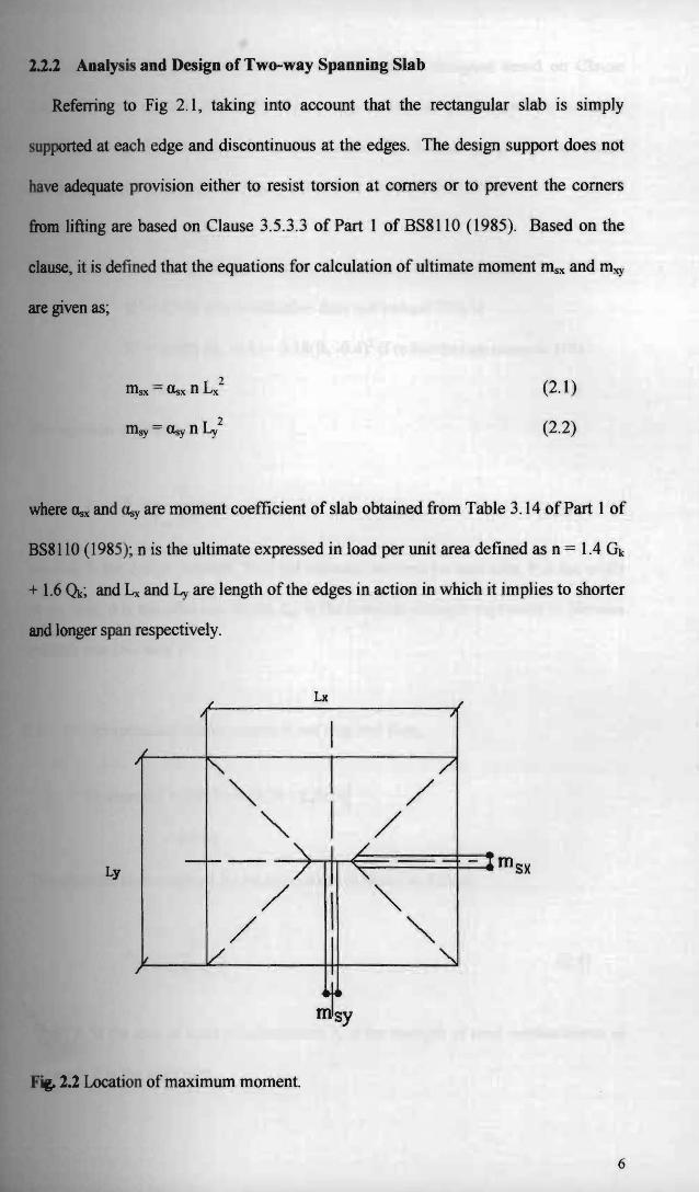