anchor
DESCRIPTION
catalogTRANSCRIPT

86
from size M8
High
perfo
rman
ce
steel
anch
ors
OVERVIEW
Anchor bolt FAZ II, zinc-plated steel
Anchor bolt FAZ A4, stainless steel A4
Anchor bolt FAZ C, highly corrosion- resistant steel 1.4529
Anchor bolt FAZ IIThe strong, easy-to-install expansion bolt for cracked concrete.
DESCRIpTION
▪ Anchorboltforpush-throughinstallation.▪ When the hexagonal nut is tightened, the tapered bolt is
pulled into the expansion clip and expands it against the drill hole wall.
▪ The FAZ II made of stainless steel A4 is for outdoorapplications and for damp rooms. Highly corrosion-resistant steel(materialnumber1.4529)forapplicationsinaggressiveatmospheres.
▪ FAZ-GSwithlargepre-assembledwasherforfixingsthroughoblong holes.
Advantages/benefits▪ Optimisedexpansionclipensuresuniform loaddistribution
for high permissible loads and small edge distances and axial spacings with structural elements, as well as secure expansion, even in cracked concrete.
▪ Installation-friendly, since only a few revolutions arenecessary to apply the torque.
Approved for:▪ Crackedandnon-cracked
concrete C20/25 to C50/60
Also suitable for:▪ ConcreteC12/15▪ Naturalstonewithdense
structure
For fixing of:▪ Steelconstructions▪ Railings▪ Consoles▪ Ladders▪ Cabletrays▪ Machines▪ Staircases▪ Gates▪ Facades▪ Windowelements▪ Woodenconstructions
FAZ II - ADVANTAGES AT A GLANCE
▪ Highesttensileandshearloads,thatmeans:moresafetywithfewertotalfixingpointsandthuslowercosts
▪ Canbeusedinextremelythinconcretepanels,startingat 80 mm thickness
▪ Smallestedgedistancesandaxialspacingsformoreapplication options
▪ Lowdriving-inenergy,smalltighteningdistanceandthus extremely handy for installation work
▪ Highsteelductilityenablessubsequentalignmentusinga hammer
The black expansion clipmakes the FAZ II easily distinguishable from its predecessor.
The distinctive collarensures that the clip stays in its posi-tion even when reinforcements are hit or there are voids when it is driven in.
The unit of cone and expansion clipincreases the tensile strength by up to 38 % in comparison to its predecessor and provides small edge distances and axial spacings, easy driving-in and a short tightening distance.
The optimised shaftallows shear forces that areup to 96 % higher than those of the predecessor product. With its optimised diameter, it can be driven in easily and if necessary can also be aligned afterwards.
STANDARDS
You will find everything that has standards on page 313 under the keyword approvals.

87
High
perfo
rman
ce
steel
anch
ors
FIRE pROTECTION
Red hot: see page 308 for informationabout fire protection..
CORROSION
All about corrosion and how you can avoid itis written on page 309.
INSTALLATION
Type of installation▪ Push-throughandpre-positioned
installation
Installation tips▪ Forlargenumberofinstallationswerecommend theanchorboltsettingtoolFABS(seepage90)toreduceinstallation time.
▪ Beforedrivingin,thehexagonnutmustbebroughtintotheoptimalinstallationposition(thethreadprojectsby2to3mm).
Anchor bolt FAZ II,zinc-plated steel
Anchor bolt FAZ II-GS (with large washer),zinc-plated steel
Type Art.-No. ID approval drill-Ø min. drill-hole depth for through fixings
effect.anchorage
depth
anchor length max. usable length
thread width across nut
Washer(outer diameter
x thickness)
qty. per box
■ ETA do td hef l t fix M SW
[mm] [mm] [mm] [mm] [mm] [mm] pcs.
FAZ II 8/10 94871 2 ■ 8 75 45 77 10 M 8 13 16 x 1,6 50
FAZ II 8/30 94877 4 ■ 8 95 45 97 30 M 8 13 16 x 1,6 50
FAZ II 8/50 94878 1 ■ 8 115 45 117 50 M 8 13 16 x 1,6 50
FAZ II 8/100 94879 8 ■ 8 165 45 167 100 M 8 13 16 x 1,6 25
FAZ II 8/150 94980 1 ■ 8 215 45 217 150 M 8 13 16 x 1,6 20
FAZ II 10/10 94981 8 ■ 10 90 60 95 10 M 10 17 20 x 2 50
FAZ II 10/20 94982 5 ■ 10 100 60 105 20 M 10 17 20 x 2 25
FAZ II 10/30 94983 2 ■ 10 110 60 115 30 M 10 17 20 x 2 25
FAZ II 10/50 94984 9 ■ 10 130 60 135 50 M 10 17 20 x 2 20
FAZ II 10/80 94985 6 ■ 10 160 60 165 80 M 10 17 20 x 2 20
FAZ II 10/100 94986 3 ■ 10 180 60 185 100 M 10 17 20 x 2 20
FAZ II 10/150 95141 5 ■ 10 230 60 235 150 M 10 17 20 x 2 20
FAZ II 12/10 95419 5 ■ 12 105 70 110 10 M 12 19 24 x 2,5 20
FAZ II 12/20 95420 1 ■ 12 115 70 120 20 M 12 19 24 x 2,5 20
FAZ II 12/30 95421 8 ■ 12 125 70 130 30 M 12 19 24 x 2,5 20
FAZ II 12/50 95446 1 ■ 12 145 70 150 50 M 12 19 24 x 2,5 20
FAZ II 12/80 95454 6 ■ 12 175 70 180 80 M 12 19 24 x 2,5 20
FAZ II 12/100 95470 6 ■ 12 195 70 200 100 M 12 19 24 x 2,5 20
FAZ II 12/150 95557 4 ■ 12 245 70 250 150 M 12 19 24 x 2,5 20
FAZ II 12/200 95605 2 ■ 12 295 70 300 200 M 12 19 24 x 2,5 10
FAZ II 16/25 95836 0 ■ 16 140 85 150 25 M 16 24 30 x 3 10
FAZ II 16/50 95864 3 ■ 16 165 85 175 50 M 16 24 30 x 3 10
FAZ II 16/100 95865 0 ■ 16 215 85 225 100 M 16 24 30 x 3 10
FAZ II 16/150 95875 9 ■ 16 265 85 275 150 M 16 24 30 x 3 10
FAZ II 16/200 95967 1 ■ 16 315 85 325 200 M 16 24 30 x 3 10
FAZ II 16/250 95968 8 ■ 16 365 85 375 250 M 16 24 30 x 3 10
FAZ II 16/300 96188 9 ■ 16 415 85 425 300 M 16 24 30 x 3 10
FAZ II 8/10 GS 1) 94872 9 ■ 8 75 45 77 10 M 8 13 24 x 2 50
FAZ II 8/30 GS 1) 96189 6 ■ 8 95 45 97 30 M 8 13 24 x 2 50
FAZ II 10/10 GS 1) 96291 6 ■ 10 90 60 95 10 M 10 17 25 x 3 50
FAZ II 10/30 GS 1) 96297 8 ■ 10 110 60 115 30 M 10 17 25 x 3 25
FAZ II 12/10 GS 1) 96303 6 ■ 12 105 70 110 10 M 12 19 30 x 3 20
FAZ II 12/30 GS 1) 96340 1 ■ 12 125 70 130 30 M 12 19 30 x 3 20
FAZ II 12/120 GS 1) 96367 8 ■ 12 215 70 220 120 M 12 19 30 x 3 20
FAZ II 16/150 GS 1) 96368 5 ■ 16 265 85 275 150 M 16 24 56 x 5 10
FAZ II 16/200 GS 1) 96370 8 ■ 16 315 85 325 200 M 16 24 56 x 5 10
1) GS = large washer
TEChNICAL DATA
88
High
perfo
rman
ce
steel
anch
ors
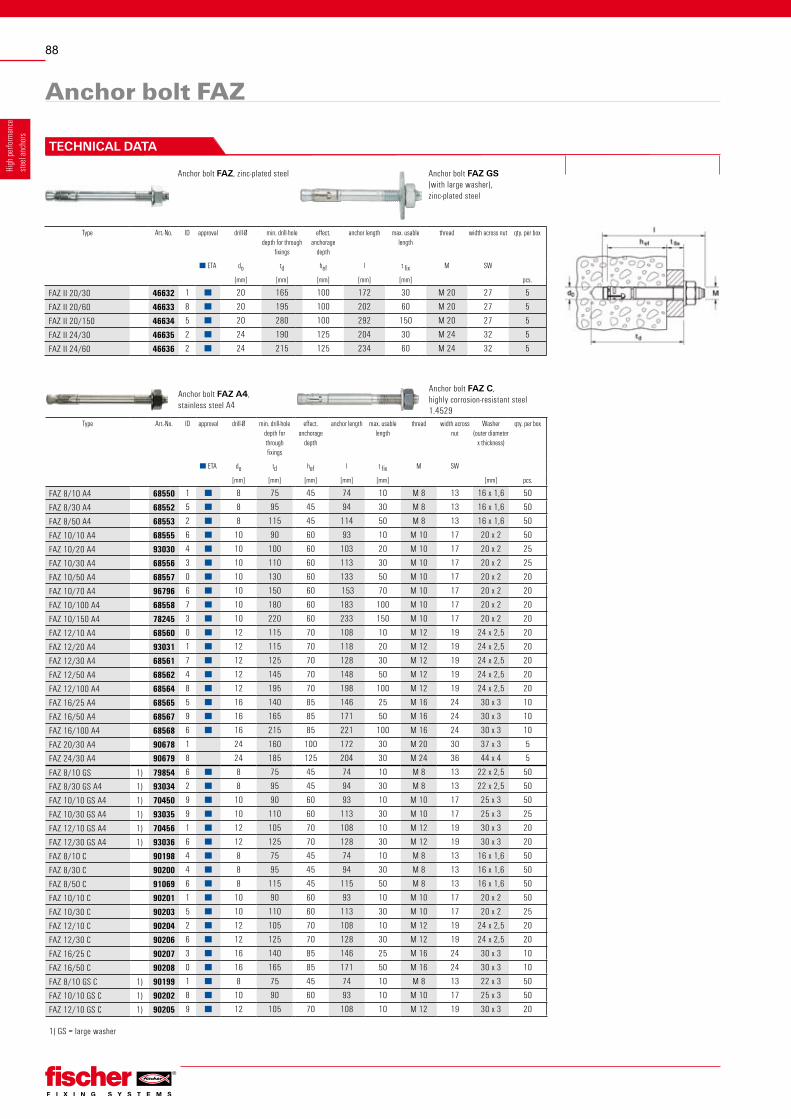
Anchor bolt FAZ A4,stainless steel A4
Anchor bolt FAZ C,highly corrosion-resistant steel 1.4529
Type Art.-No. ID approval drill-Ø min. drill-hole depth for through fixings
effect.anchorage
depth
anchor length max. usable length
thread width across nut
Washer(outer diameter
x thickness)
qty. per box
■ ETA do td hef l t fix M SW
[mm] [mm] [mm] [mm] [mm] [mm] pcs.
FAZ 8/10 A4 68550 1 ■ 8 75 45 74 10 M 8 13 16 x 1,6 50
FAZ 8/30 A4 68552 5 ■ 8 95 45 94 30 M 8 13 16 x 1,6 50
FAZ 8/50 A4 68553 2 ■ 8 115 45 114 50 M 8 13 16 x 1,6 50
FAZ 10/10 A4 68555 6 ■ 10 90 60 93 10 M 10 17 20 x 2 50
FAZ 10/20 A4 93030 4 ■ 10 100 60 103 20 M 10 17 20 x 2 25
FAZ 10/30 A4 68556 3 ■ 10 110 60 113 30 M 10 17 20 x 2 25
FAZ 10/50 A4 68557 0 ■ 10 130 60 133 50 M 10 17 20 x 2 20
FAZ 10/70 A4 96796 6 ■ 10 150 60 153 70 M 10 17 20 x 2 20
FAZ 10/100 A4 68558 7 ■ 10 180 60 183 100 M 10 17 20 x 2 20
FAZ 10/150 A4 78245 3 ■ 10 220 60 233 150 M 10 17 20 x 2 20
FAZ 12/10 A4 68560 0 ■ 12 115 70 108 10 M 12 19 24 x 2,5 20
FAZ 12/20 A4 93031 1 ■ 12 115 70 118 20 M 12 19 24 x 2,5 20
FAZ 12/30 A4 68561 7 ■ 12 125 70 128 30 M 12 19 24 x 2,5 20
FAZ 12/50 A4 68562 4 ■ 12 145 70 148 50 M 12 19 24 x 2,5 20
FAZ 12/100 A4 68564 8 ■ 12 195 70 198 100 M 12 19 24 x 2,5 20
FAZ 16/25 A4 68565 5 ■ 16 140 85 146 25 M 16 24 30 x 3 10
FAZ 16/50 A4 68567 9 ■ 16 165 85 171 50 M 16 24 30 x 3 10
FAZ 16/100 A4 68568 6 ■ 16 215 85 221 100 M 16 24 30 x 3 10
FAZ 20/30 A4 90678 1 24 160 100 172 30 M 20 30 37 x 3 5
FAZ 24/30 A4 90679 8 24 185 125 204 30 M 24 36 44 x 4 5
FAZ 8/10 GS 1) 79854 6 ■ 8 75 45 74 10 M 8 13 22 x 2,5 50
FAZ 8/30 GS A4 1) 93034 2 ■ 8 95 45 94 30 M 8 13 22 x 2,5 50
FAZ 10/10 GS A4 1) 70450 9 ■ 10 90 60 93 10 M 10 17 25 x 3 50
FAZ 10/30 GS A4 1) 93035 9 ■ 10 110 60 113 30 M 10 17 25 x 3 25
FAZ 12/10 GS A4 1) 70456 1 ■ 12 105 70 108 10 M 12 19 30 x 3 20
FAZ 12/30 GS A4 1) 93036 6 ■ 12 125 70 128 30 M 12 19 30 x 3 20
FAZ 8/10 C 90198 4 ■ 8 75 45 74 10 M 8 13 16 x 1,6 50
FAZ 8/30 C 90200 4 ■ 8 95 45 94 30 M 8 13 16 x 1,6 50
FAZ 8/50 C 91069 6 ■ 8 115 45 115 50 M 8 13 16 x 1,6 50
FAZ 10/10 C 90201 1 ■ 10 90 60 93 10 M 10 17 20 x 2 50
FAZ 10/30 C 90203 5 ■ 10 110 60 113 30 M 10 17 20 x 2 25
FAZ 12/10 C 90204 2 ■ 12 105 70 108 10 M 12 19 24 x 2,5 20
FAZ 12/30 C 90206 6 ■ 12 125 70 128 30 M 12 19 24 x 2,5 20
FAZ 16/25 C 90207 3 ■ 16 140 85 146 25 M 16 24 30 x 3 10
FAZ 16/50 C 90208 0 ■ 16 165 85 171 50 M 16 24 30 x 3 10
FAZ 8/10 GS C 1) 90199 1 ■ 8 75 45 74 10 M 8 13 22 x 3 50
FAZ 10/10 GS C 1) 90202 8 ■ 10 90 60 93 10 M 10 17 25 x 3 50
FAZ 12/10 GS C 1) 90205 9 ■ 12 105 70 108 10 M 12 19 30 x 3 20
1) GS = large washer
Anchor bolt FAZ
Anchor bolt FAZ, zinc-plated steel Anchor bolt FAZ GS(with large washer),zinc-plated steel
Type Art.-No. ID approval drill-Ø min. drill-hole depth for through
fixings
effect.anchorage
depth
anchor length max. usable length
thread width across nut qty. per box
■ ETA do td hef l t fix M SW
[mm] [mm] [mm] [mm] [mm] pcs.
FAZ II 20/30 46632 1 ■ 20 165 100 172 30 M 20 27 5
FAZ II 20/60 46633 8 ■ 20 195 100 202 60 M 20 27 5
FAZ II 20/150 46634 5 ■ 20 280 100 292 150 M 20 27 5
FAZ II 24/30 46635 2 ■ 24 190 125 204 30 M 24 32 5
FAZ II 24/60 46636 2 ■ 24 215 125 234 60 M 24 32 5
TEChNICAL DATA

89
High
perfo
rman
ce
steel
anch
ors
LOADS
Mean ultimate loads. design resistant and recommended loads for single anchors of fischer Anchor bolt FAZ with large axial spacing and edge distance
Non-cracked concrete Cracked concreteAnchor size M 8 M 10 M 12 M 16 M 20 M 24 M 8 M 10 M 12 M 16 M 20 M 24Effective anchorage depth hef [mm] 45 60 70 85 100 125 45 60 70 85 100 125Drill hole depth h1 ≧ [mm] 55 75 90 110 130 155 55 75 90 110 130 155Drill hole diameter d0 [mm] 8 10 12 16 20 24 8 10 12 16 20 24
Mean ultimate loads Nu and Vu [kN]
Tensile 0° Nu [kN]gvz 15.9 26.4 38.6 52.9 55.1 79.2 13.8 22.0 27.7 37.0 42.3 47.3A4 16.8 26.8 35.3 48.4 65.7 93.3 10.3* 18.1 24.6 37.0 47.3 66.0C 16.0* 25.4* 35.3 48.4 — — 12.0 21.0 27.8 37.0 — —
Shear 90° Vu [kN]
gvz 20.7 29.5 43.0 78.5 64.6 91.7 20.7 29.5 43.0 78.5 64.4 91.7A4 19.8* 31.2* 40.5* 54.2* 92.6* 148.3* 19.8* 31.2* 40.5* 54.2* 92.6* 148.3*C 15.4* 24.4* 35.4* 65.9* — — 15.4* 24.4* 35.4* 65.9* — —
Design resistant loads NRd and VRd [kN]
Tensile 0° NRd [kN]gvz 7.2 11.8 17.7 26.3 28.7 43.3 6.0 9.3 13.3 18.8 22.7 33.5A4 8.3 14.7 18.7 26.7 34.0 47.3 5.8 9.5 13.9 18.8 24.0 33.3C 8.3 14.7 18.7 26.7 — — 5.8 9.5 14.1 18.8 — —
Shear 90° VRd
gvz(14.0) 2)
9.6(22.4) 2)
16.0(32.8) 2)
23.6(57.2) 2)
44.041.6 57.3
(14.0) 2)
9.6(22.4) 2)
16.0(32.8) 2)
23.6(52.7) 2)
44.041.6 57.3
[kN] A4 8.8 14.4 20.8 36.0 61.1 78.8 8.8 14.4 20.8 36.0 48.0 67.1C 8.7 13.3 20.0 36.7 — — 7.2 13.3 20.0 36.7 — —
Recommended loads Nrec and Vrec [kN]
Tensile 0° Nrec [kN]gvz 5.1 8.4 12.7 18.8 20.5 31.0 4.3 6.7 9.5 13.4 16.2 24.0A4 6.0 10.5 13.3 19.0 24.3 33.8 4.1 6.8 10.0 13.4 17.1 23.8C 6.0 10.5 13.3 19.0 — — 4.1 6.8 10.0 13.4 — —
Shear 90° Vrec [kN]gvz
(10.0) 2)
6.9(16.0) 2)
11.4(23.4) 2)
16.9(40.9) 2)
31.429.7 41.0
(10.0) 2)
6.9(16.0) 2)
11.4(23.4) 2)
16.9(37.6) 2)
31.429.7 41.0
A4 6.3 10.3 14.9 25.7 43.7 56.3 6.3 10.3 14.9 25.7 34.3 47.9C 6.2 9.5 14.3 26.2 — — 5.2 9.5 14.3 26.2 — —
Recommended bending moment Mrec [Nm]
Mrec [Nm]gvz 14.9 33.1 52.6 133.1 222.3 288.6 14.9 33.1 52.6 133.1 222.3 288.6A4 13.1 26.8 46.8 109.0 232.0 360.0 13.1 26.8 46.8 109.0 232.0 360.0C 12.4 24.8 43.8 111.0 — — 12.4 24.8 43.8 111.0 — —
Component dimensions, minimum axial spacings and edge distancesStandard structural component thickness ( ≧ 2 x hef )
hmin,1 [mm] 100 120 140 170 200 250 100 120 140 170 200 250
Min. axial spacing1)
smin [mm] gvz 40 40 50 60 95 120 35 40 45 60 95 120
for c ≧ [mm] gvz 50 60 70 95 200 200 50 55 70 95 160 165
smin [mm] A4 / C 50 55 65 75 100 125 40 55 65 75 100 125
for c ≧ [mm] A4 / C 50 70 100 120 200 250 50 70 75 100 200 250
Min. edge distance1)
cmin [mm] gvz 40 45 55 65 130 150 40 45 55 65 100 120for s ≧ [mm] gvz 100 80 110 150 245 270 70 80 110 150 220 220
cmin [mm] A4 / C 50 55 65 85 200 250 45 55 65 65 200 250for s ≧ [mm] A4 / C 50 120 150 165 100 125 60 90 100 175 100 125
Reduced structural component thickness ( < 2 x hef )
hmin,2 [mm] 80 100 120 140 — — 80 100 120 140 — —
Min. axial spacing1)
smin [mm] gvz 35 40 50 80 — — 35 40 50 80 — —for c ≧ [mm] gvz 70 100 90 130 — — 70 100 90 130 — —
smin [mm] A4 / C — — — — — — — — — — — —for c ≧ [mm] A4 / C — — — — — — — — — — — —
Min. edge distance1)
cmin [mm] gvz 40 60 60 65 — — 40 60 60 65 — —for s ≧ [mm] gvz 100 90 120 180 — — 100 90 120 180 — —
cmin [mm] A4 / C — — — — — — — — — — — —
for s ≧ [mm] A4 / C — — — — — — — — — — — —
Required torque Tinst [Nm] 20 45 60 110 200 270 20 45 60 110 200 270
* steel failure decisive1) For min. axial spacing and min. edge distance the above described loads have to be reduced! (See “Technical Handbook” or design software “CC-Compufix”)2) In general the relevant kind of failure has to be defined by the designing engineer. Simplifying for a thickness of the fixture ≧ 15 mm (size M8), ≧ 20 mm (sizes M10 and M12) and respectively ≧ 25 mm
(size M16) as well as a nominal useful length (tfix,nom) of the used anchor type not exceeding 50 mm the values in brackets can be used.All load values apply for concrete C20/25 without edge or spacing influences.Design resistant loads: material safety factor γM is included. Material safety factor γM depends on type of anchor.Recommended loads: material safety factor γM and safety factor for load γL = 1.4 are included.
The conditions of application may differ from those given in the European Technical Approval. For further detailed information about European Technical Approvals please contact the responsible fischer representation in your country.