anchor fastening technology manual 09 / 2012 - hilti.cz · pdf filematerial has insufficient...
TRANSCRIPT

10 / 20120
Anchor FasteningTechnology Manual
09 / 2012
Forword
10 / 2012 1
Foreword
Dear customer,
As it is our ambition to be the worldwide leader in fastening technology, we are continously striving to provide you with state-of-the-art technical information reflecting the latest developments in codes, regulations and approvals and technical information for our products.
The Fastening Technology Manuals for Post-installed Anchors and for Anchor Channel reflect our ongoing investment into long term research and development of leading fastening products.
This Fastening Technology Manual for Post-installed Anchors should be a valuable support tool for you when solving fastening tasks with Post-installed Anchor fastening technology. It should provide you with profound technical know-how, and help you to be more productive in your daily work without any compromise regarding reliability and safety.
As we strive to be a reliable partner for you, we would very much appreciate your feedback for improvements. We are available at any time to answer additional questions that even go beyond this content.
Raimund Zaggl
Business Unit Anchors
Important notices
10 / 20122
Important notices1. Construction materials and conditions vary on different sites. If it is suspected that the base
material has insufficient strength to achieve a suitable fastening, contact the Hilti Technical Advisory Service.
2. The information and recommendations given herein are based on the principles, formulae and safety factors set out in the Hilti technical instructions, the operating manuals, the setting instructions, the installation manuals and other data sheets that are believed to be correct at the time of writing. The data and values are based on the respective average values obtained from tests under laboratory or other controlled conditions. It is the users responsibility to use the data given in the light of conditions on site and taking into account the intended use of the products concerned. The user has to check the listed prerequisites and criteria conform with the conditions actually existing on the job-site. Whilst Hilti can give general guidance and advice, the nature of Hilti products means that the ultimate responsibility for selecting the right product for a particular application must lie with the customer.
3. All products must be used, handled and applied strictly in accordance with all current instructions for use published by Hilti, i.e. technical instructions, operating manuals, setting instructions, installation manuals and others.
4. All products are supplied and advice is given subject to the Hilti terms of business.
5. Hilti´s policy is one of continuous development. We therefore reserve the right to alter specifications, etc. without notice.
6. The given mean ultimate loads and characteristic data in the Anchor Fastening Technology Manual reflect actual test results and are thus valid only for the indicated test conditions. Due to variations in local base materials, on-site testing is required to determine performance at any specific site.
7. Hilti is not obligated for direct, indirect, incidental or consequential damages, losses or expenses in connection with, or by reason of, the use of, or inability to use the products for any purpose. Implied warranties of merchantability or fitness for a particular purpose are specifally excluded.
Hilti CorporationFL-9494 SchaanPrincipality of Liechtensteinwww.hilti.com
Hilti = registred trademark of the Hilti Corporation, Schaan
Contents
10 / 20124
Contents
Anchor technology and design ................................................................................................7
Anchor selector.....................................................................................................................................8
Legal environment ..............................................................................................................................20
Approvals ...........................................................................................................................................22
Base material .....................................................................................................................................28
Anchor design ....................................................................................................................................34
Design example..................................................................................................................................44
Corrosion............................................................................................................................................48
Dynamic loads (seismic, fatigue, shock) .............................................................................................52
Resistance to fire................................................................................................................................58
Mechanical anchoring systems ..............................................................................................71
HDA Design anchor............................................................................................................................72
HSL-3 carbon steel, heavy duty anchor ..............................................................................................88
HSL-GR stainless steel, heavy duty anchor......................................................................................100
HSC-A Safety anchor .......................................................................................................................110
HSC-I Safety anchor.........................................................................................................................120
HST Stud anchor ..............................................................................................................................130
HSA Stud anchor..............................................................................................................................140
HSV Stud anchor..............................................................................................................................160
HLC Sleeve anchor ..........................................................................................................................170
HAM Hard sleeve anchor..................................................................................................................176
HUS-HR Screw anchor, stainless steel.............................................................................................178
HUS Screw anchor, carbon steel ......................................................................................................194
HUS 6 Screw anchor, Redundant fastening......................................................................................210
HUS-A 6 / HUS-H 6 / HUS-I 6 / HUS-P 6 Screw anchor in precast prestressed hollow core slabs....218
HUS 6 / HUS-S 6 Screw anchor .......................................................................................................224
HKD Push-in anchor, Single anchor application................................................................................230
HKD Push-in anchor, Redundant fastening ......................................................................................244
HKV Push-in anchor, Single anchor application................................................................................252
HUD-1 Universal anchor...................................................................................................................256
HUD-L Universal anchor...................................................................................................................262
HLD Light duty anchor ......................................................................................................................266
HRD-U 10 / - S 10 / -U 14 Frame anchor ..........................................................................................270
HRD Frame anchor, Redundant fastening ........................................................................................276
HPS-1 Impact anchor .......................................................................................................................294
HHD-S Cavity anchor .......................................................................................................................298
HCA Coil anchor...............................................................................................................................300
HSP / HFP Drywall plug....................................................................................................................302
HA 8 Ring / hook anchor...................................................................................................................304
DBZ Wedge anchor ..........................................................................................................................308
HT Metal frame anchor .....................................................................................................................312
HK Ceiling anchor.............................................................................................................................316
HPD Aerated concrete anchor ..........................................................................................................322
HKH Hollow deck anchor..................................................................................................................328
HTB Hollow wall metal anchor ..........................................................................................................332
IDP Insulation fastener .....................................................................................................................336
IZ Insulation fastener ........................................................................................................................340
IDMS / IDMR Insulation fastener ......................................................................................................344

Contents
10 / 2012 5
Adhesive anchoring systems ...............................................................................................349
HVZ Adhesive anchor.......................................................................................................................350
HVU with HAS/HAS-E rod adhesive anchor .....................................................................................362
HVU with HIS-(R)N adhesive anchor ................................................................................................372
Hilti HIT-RE 500-SD with HIT-V rod ..................................................................................................382
Hilti HIT-RE 500-SD with HIS-(R)N...................................................................................................398
Hilti HIT-RE 500-SD with rebar .........................................................................................................410
Hilti HIT-RE 500 with HIT-V / HAS in hammer drilled holes ..............................................................424
Hilti HIT-RE 500 with HIT-V / HAS in diamond drilled holes ..............................................................440
Hilti HIT-RE 500 with HIS-(R)N.........................................................................................................450
Hilti HIT-RE 500 with rebar in hammer drilled holes..........................................................................464
Hilti HIT-RE 500 with rebar in diamond drilled holes .........................................................................480
Hilti HIT-HY 200 with HIT-Z ..............................................................................................................490
Hilti HIT-HY 200 with HIT-V ..............................................................................................................510
Hilti HIT-HY 200 with HIS-(R)N.........................................................................................................528
Hilti HIT-HY 200 with rebar ...............................................................................................................544
Hilti HIT-HY 150 MAX with HIT-TZ....................................................................................................560
Hilti HIT-HY 150 MAX with HIT-V / HAS ...........................................................................................572
Hilti HIT-HY 150 MAX with HIS-(R)N ................................................................................................590
Hilti HIT-HY 150 MAX with rebar ......................................................................................................602
Hilti HIT-CT 1 with HIT-V ..................................................................................................................616
Hilti HIT-HY 150 with HIT-V / HAS....................................................................................................632
Hilti HIT-HY 150 with HIS-(R)N.........................................................................................................648
Hilti HIT-HY 150 with rebar ...............................................................................................................660
Hilti HIT-ICE with HIT-V / HAS..........................................................................................................674
Hilti HIT-ICE with HIS-(R)N...............................................................................................................686
Hilti HIT-ICE with rebar .....................................................................................................................698
Hilti HIT-HY 70 injection mortar for masonry.....................................................................................708
HRT-WH Rail anchor with Hilti HVU or Hilti HIT-RE 500...................................................................734
HRT Rail anchor with Hilti HIT-RE 500 .............................................................................................738
HRC / HRC-DB Rail anchor with Hilti HIT-RE 500 ............................................................................742
HRA Rail anchor with Hilti HIT-RE 500 or HVU-G/EA glass capsule.................................................746
HRT-I Rail anchor with Hilti HIT-RE 500 ...........................................................................................750
HRT-IP Rail Anchor for cast-in/top down construction method..........................................................754
Post-installed rebar connections .........................................................................................759
Basics, design and installation of post installed rebars .....................................................................760
Hilti HIT-RE 500-SD post-installed rebars.........................................................................................798
Hilti HIT-RE 500 post-installed rebars...............................................................................................810
Hilti HIT-HY 200 post-installed rebars...............................................................................................822
Hilti HIT-HY 150 post-installed rebars...............................................................................................830
Hilti HIT-HY 150 MAX post-installed rebars ......................................................................................838
Hilti worldwide........................................................................................................................848
HUS-HR Screw anchorstainless steel
10 / 2012178
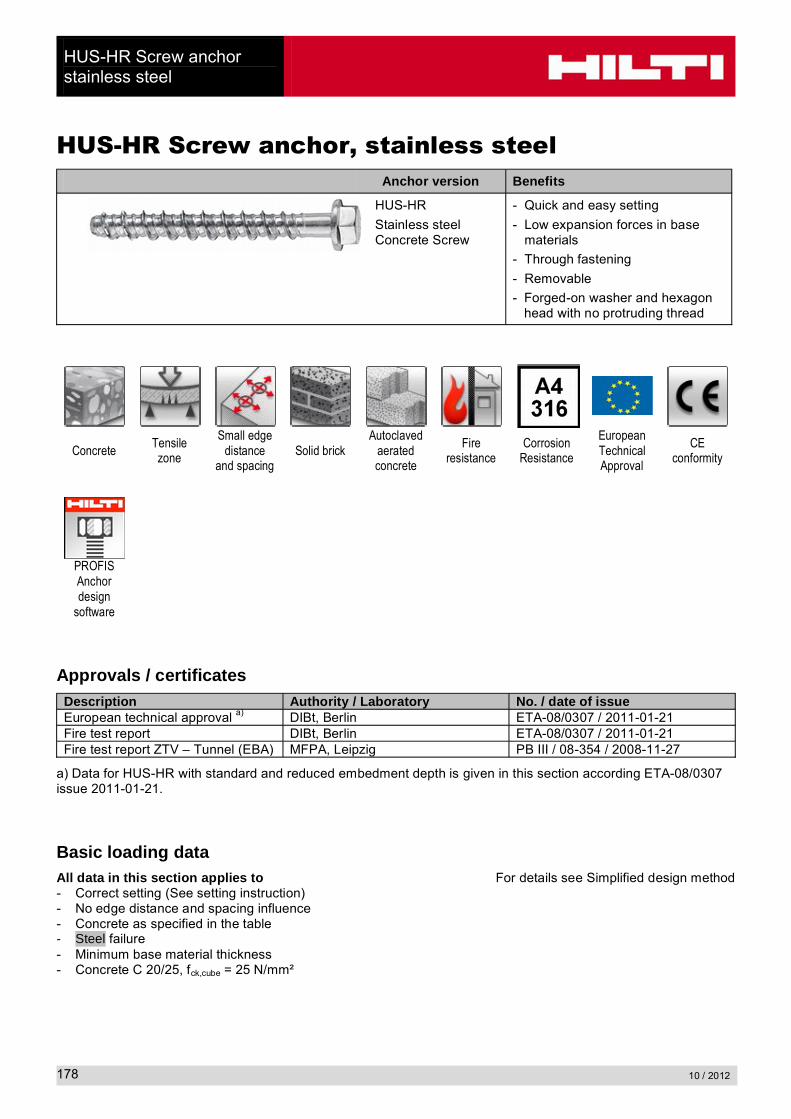
HUS-HR Screw anchor, stainless steelAnchor version Benefits
HUS-HR
Stainless steel Concrete Screw
- Quick and easy setting
- Low expansion forces in base materials
- Through fastening
- Removable
- Forged-on washer and hexagon head with no protruding thread
ConcreteTensile zone
Small edge distance
and spacingSolid brick
Autoclaved aerated concrete
Fire resistance
Corrosion Resistance
European Technical Approval
CE conformity
PROFIS Anchor design
software
Approvals / certificatesDescription Authority / Laboratory No. / date of issueEuropean technical approval a) DIBt, Berlin ETA-08/0307 / 2011-01-21Fire test report DIBt, Berlin ETA-08/0307 / 2011-01-21Fire test report ZTV – Tunnel (EBA) MFPA, Leipzig PB III / 08-354 / 2008-11-27
a) Data for HUS-HR with standard and reduced embedment depth is given in this section according ETA-08/0307issue 2011-01-21.
Basic loading dataAll data in this section applies to For details see Simplified design method- Correct setting (See setting instruction)- No edge distance and spacing influence- Concrete as specified in the table- Steel failure- Minimum base material thickness- Concrete C 20/25, fck,cube = 25 N/mm²
HUS-HR Screw anchorstainless steel
10 / 2012 179
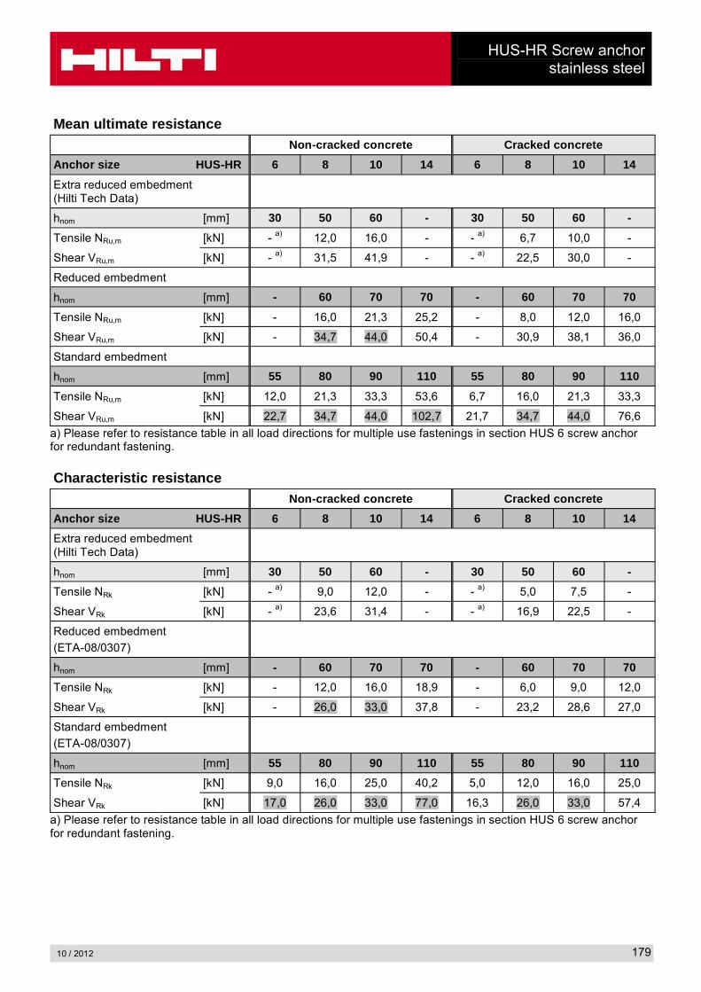
Mean ultimate resistance Non-cracked concrete Cracked concrete
Anchor size HUS-HR 6 8 10 14 6 8 10 14
Extra reduced embedment (Hilti Tech Data)
hnom [mm] 30 50 60 - 30 50 60 -
Tensile NRu,m [kN] - a) 12,0 16,0 - - a) 6,7 10,0 -
Shear VRu,m [kN] - a) 31,5 41,9 - - a) 22,5 30,0 -
Reduced embedment
hnom [mm] - 60 70 70 - 60 70 70
Tensile NRu,m [kN] - 16,0 21,3 25,2 - 8,0 12,0 16,0
Shear VRu,m [kN] - 34,7 44,0 50,4 - 30,9 38,1 36,0
Standard embedment
hnom [mm] 55 80 90 110 55 80 90 110
Tensile NRu,m [kN] 12,0 21,3 33,3 53,6 6,7 16,0 21,3 33,3
Shear VRu,m [kN] 22,7 34,7 44,0 102,7 21,7 34,7 44,0 76,6
a) Please refer to resistance table in all load directions for multiple use fastenings in section HUS 6 screw anchor for redundant fastening.
Characteristic resistanceNon-cracked concrete Cracked concrete
Anchor size HUS-HR 6 8 10 14 6 8 10 14
Extra reduced embedment (Hilti Tech Data)
hnom [mm] 30 50 60 - 30 50 60 -
Tensile NRk [kN] - a) 9,0 12,0 - - a) 5,0 7,5 -
Shear VRk [kN] - a) 23,6 31,4 - - a) 16,9 22,5 -
Reduced embedment
(ETA-08/0307)
hnom [mm] - 60 70 70 - 60 70 70
Tensile NRk [kN] - 12,0 16,0 18,9 - 6,0 9,0 12,0
Shear VRk [kN] - 26,0 33,0 37,8 - 23,2 28,6 27,0
Standard embedment
(ETA-08/0307)
hnom [mm] 55 80 90 110 55 80 90 110
Tensile NRk [kN] 9,0 16,0 25,0 40,2 5,0 12,0 16,0 25,0
Shear VRk [kN] 17,0 26,0 33,0 77,0 16,3 26,0 33,0 57,4
a) Please refer to resistance table in all load directions for multiple use fastenings in section HUS 6 screw anchor for redundant fastening.
HUS-HR Screw anchorstainless steel
10 / 2012180
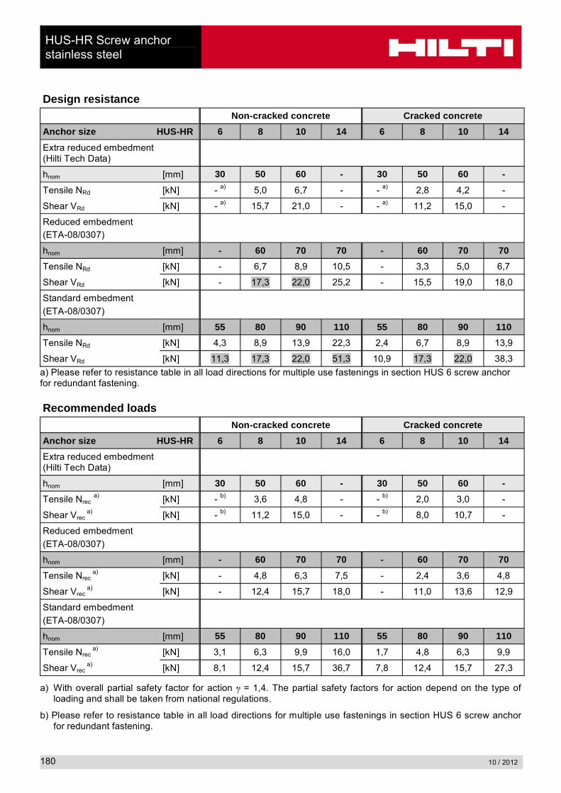
Design resistanceNon-cracked concrete Cracked concrete
Anchor size HUS-HR 6 8 10 14 6 8 10 14
Extra reduced embedment (Hilti Tech Data)
hnom [mm] 30 50 60 - 30 50 60 -
Tensile NRd [kN] - a) 5,0 6,7 - - a) 2,8 4,2 -
Shear VRd [kN] - a) 15,7 21,0 - - a) 11,2 15,0 -
Reduced embedment(ETA-08/0307)
hnom [mm] - 60 70 70 - 60 70 70
Tensile NRd [kN] - 6,7 8,9 10,5 - 3,3 5,0 6,7
Shear VRd [kN] - 17,3 22,0 25,2 - 15,5 19,0 18,0
Standard embedment
(ETA-08/0307)
hnom [mm] 55 80 90 110 55 80 90 110
Tensile NRd [kN] 4,3 8,9 13,9 22,3 2,4 6,7 8,9 13,9
Shear VRd [kN] 11,3 17,3 22,0 51,3 10,9 17,3 22,0 38,3
a) Please refer to resistance table in all load directions for multiple use fastenings in section HUS 6 screw anchor for redundant fastening.
Recommended loadsNon-cracked concrete Cracked concrete
Anchor size HUS-HR 6 8 10 14 6 8 10 14
Extra reduced embedment (Hilti Tech Data)
hnom [mm] 30 50 60 - 30 50 60 -
Tensile Nreca) [kN] - b) 3,6 4,8 - - b) 2,0 3,0 -
Shear Vreca) [kN] - b) 11,2 15,0 - - b) 8,0 10,7 -
Reduced embedment
(ETA-08/0307)
hnom [mm] - 60 70 70 - 60 70 70
Tensile Nreca) [kN] - 4,8 6,3 7,5 - 2,4 3,6 4,8
Shear Vreca) [kN] - 12,4 15,7 18,0 - 11,0 13,6 12,9
Standard embedment
(ETA-08/0307)
hnom [mm] 55 80 90 110 55 80 90 110
Tensile Nreca) [kN] 3,1 6,3 9,9 16,0 1,7 4,8 6,3 9,9
Shear Vreca) [kN] 8,1 12,4 15,7 36,7 7,8 12,4 15,7 27,3
a) With overall partial safety factor for action = 1,4. The partial safety factors for action depend on the type of loading and shall be taken from national regulations.
b) Please refer to resistance table in all load directions for multiple use fastenings in section HUS 6 screw anchor for redundant fastening.

HUS-HR Screw anchorstainless steel
10 / 2012 181
Basic loading data for single anchor in solid masonry unitsAll data in this section applies to- Load values valid for holes drilled with TE rotary hammers in hammering mod- Correct anchor setting (see instruction for use, setting details)- The core / material ratio may not exceed 15% of a bed joint area. - The brim area around holes must be at least 70mm - Edge distances, spacing and other influences, see below
Recommended loadsHilti
Base material Anchor size �������� �������� ���������
Germany, Austria, Switzerland hnom [mm] 55 60 70
Solid clay brickMz12/2,0 DIN 105/
EN 771-1fb
a) 12 N/mm²
Tensile Nrec [kN] 0,9 1,0 1,1
Shear Vrec [kN] 1,4 2,0 2,3
Solid sand-lime brick KS 12/2,0 DIN 106/
EN 771-2
fb a) 12 N/mm²
Tensile Nrec[kN]
0,6 0,6 1,0
Shear Vrec[kN]
0,9 1,1 1,7
Aerated concrete PPW 6-0,4 DIN 4165/
EN 771-4fb
a) 6 N/mm²
Tensile Nrec[kN]
0,2 0,2 0,4
Shear Vrec[kN]
0,4 0,4 0,9
a) fb = brick strength
HUS-HR Screw anchorstainless steel
10 / 2012182
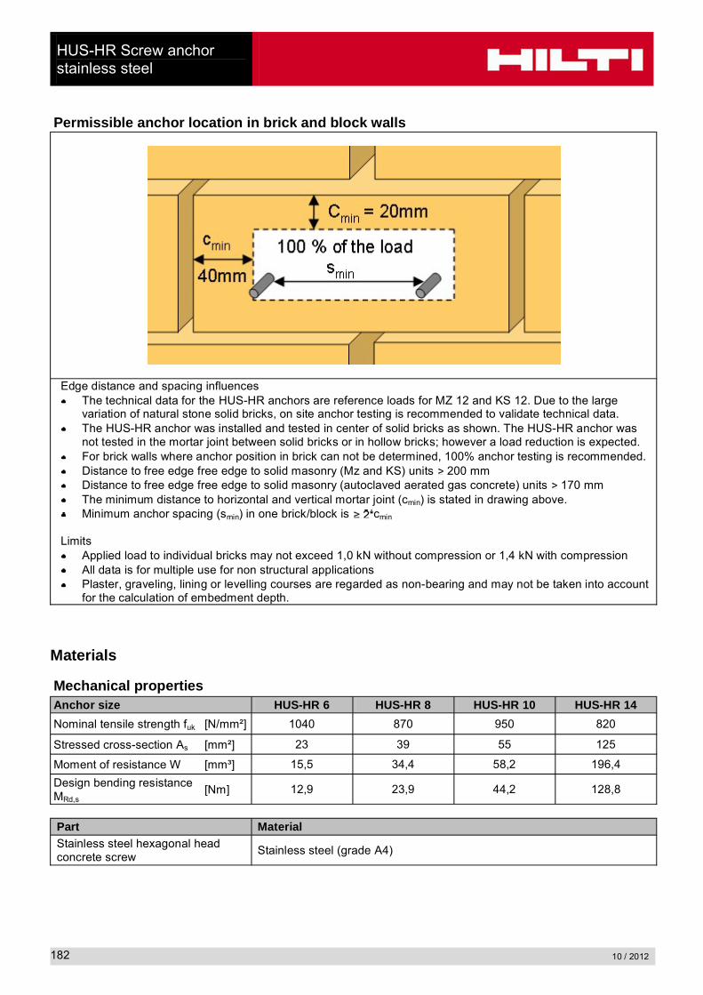
Permissible anchor location in brick and block walls
Edge distance and spacing influencesThe technical data for the HUS-HR anchors are reference loads for MZ 12 and KS 12. Due to the large variation of natural stone solid bricks, on site anchor testing is recommended to validate technical data.The HUS-HR anchor was installed and tested in center of solid bricks as shown. The HUS-HR anchor was not tested in the mortar joint between solid bricks or in hollow bricks; however a load reduction is expected.For brick walls where anchor position in brick can not be determined, 100% anchor testing is recommended.Distance to free edge free edge to solid masonry (Mz and KS) units 200 mmDistance to free edge free edge to solid masonry (autoclaved aerated gas concrete) units 170 mmThe minimum distance to horizontal and vertical mortar joint (cmin) is stated in drawing above.Minimum anchor spacing (smin) in one brick/block is cmin
LimitsApplied load to individual bricks may not exceed 1,0 kN without compression or 1,4 kN with compressionAll data is for multiple use for non structural applicationsPlaster, graveling, lining or levelling courses are regarded as non-bearing and may not be taken into account for the calculation of embedment depth.
Materials
Mechanical propertiesAnchor size HUS-HR 6 HUS-HR 8 HUS-HR 10 HUS-HR 14
Nominal tensile strength fuk [N/mm²] 1040 870 950 820
Stressed cross-section As [mm²] 23 39 55 125
Moment of resistance W [mm³] 15,5 34,4 58,2 196,4
Design bending resistance MRd,s
[Nm] 12,9 23,9 44,2 128,8
Part MaterialStainless steel hexagonal head concrete screw
Stainless steel (grade A4)

HUS-HR Screw anchorstainless steel
10 / 2012 183
Anchor dimensions
Dimensions Anchor version ls
[mm]ds
[mm]dk
[mm]
HUS-HR 6 35 … 70 7,5 5,4
HUS-HR 8 55 … 105 10,1 7,1
HUS-HR 10 65 … 130 12,3 8,4
HUS-HR 14 80 … 135 16,5 12,6
Setting
Recommended installation equipmentAnchor size �������� �������� ��������� ���������
Rotary hammer ���������� ���������� ����������� ������������
drill bit TE-C3X 6/17 TE-C3X 8/17 TE-C3X 10/22 TE-C3X 14/22
Socket wrench insert S-NSD 13 ½ (L) S-NSD 13 ½ (L) S-NSD 15 ½ (L) S-NSD 21 ½
Impact screw driverHilti SIW 144 or 121
Hilti TKI 2500Hilti SI 100
Setting instruction
For detailed information on installation see instruction for use given with the package of the product.

HUS-HR Screw anchorstainless steel
10 / 2012184
Setting details: depth of drill hole h1 and effective anchorage depth hef
Setting detailsAnchor version HUS-HR 6 8 10 14
Nominal embedment depth hnom [mm] 30 55 50 60 80 60 70 90 70 110
Nominal diameter of drill bit do [mm] 6 8 10 14
Cutting diameter of drill bit dcut [mm] 6,4 8,45 10,45 14,5
Depth of drill hole h1 [mm] 40 65 60 70 90 70 80 100 80 120
Diameter of clearance hole in the fixture
df [mm] 9 12 14 18
Effective anchorage depth hef [mm] 23 45 38 47 64 46 54 71 52 86
Max. fastening thickness tfix [mm] ls – hnom
Max. installation torque
Concrete Tinst [Nm] 20 - a) 35 - a) - a) 45 45 45 65 65
Solid m. Mz 12 Tinst [Nm] - b) 10 - b) 16 16 - 20 20 - b) - b)
Solid m. KS 12 Tinst [Nm] - b) 10 - b) 16 16 - 20 20 - b) - b)
Aerated conc. Tinst [Nm] - b) 4 - b) 8 8 - 10 10 - b) - b)
a) Hilti recommends machine setting only in concreteb) Hilti does not recommend this setting process for this application.

HUS-HR Screw anchorstainless steel
10 / 2012 185
Base material thickness, anchor spacing and edge distance Anchor size HUS-HR 6 HUS-HR 8 HUS-HR 10 HUS-HR 14
Nominal embedment depth
hnom [mm] 30 55 50 60 80 60 70 90 70 110
Minimum base material thickness non-cracked concrete
hmin [mm] 100 100 100 100 120 120 120 140 140 160
Minimum spacing smin [mm] 40 40 45 45 50 50 50 50 50 60
Minimum edge distance
cmin [mm] 40 40 45 45 50 50 50 50 50 60
Critical spacing for concrete cone and splitting failure
scr,N =
scr,sp[mm] 69 135 114 141 192 166 194 256 187 310
Critical edge distance for concrete cone and splitting failure
ccr,N =
ccr,sp[mm] 35 68 57 71 96 83 97 128 94 155
For spacing (edge distance) smaller than critical spacing (critical edge distance) the design loads have to be reduced (see system design resistance).
Critical spacing and critical edge distance for splitting failure apply only for non-cracked concrete. For cracked concrete only the critical spacing and critical edge distance for concrete cone failure are decisive.
Simplified design methodSimplified version of the design method according ETAG 001, Annex C. Design resistance according data given in ETA-08/0307 issue 2011.01.21.
Influence of concrete strengthInfluence of edge distanceInfluence of spacingValid for a group of two anchors. (The method may also be applied for anchor groups with more than two anchors or more than one edge. The influencing factors must then be considered for each edge distance and spacing. The calculated design loads are then on the save side: They will be lower than the exact values according ETAG 001, Annex C. To avoid this, it is recommended to use the anchor design software PROFIS anchor)
The design method is based on the following simplification:No different loads are acting on individual anchors (no eccentricity)
The values are valid for one anchor (single point fastening), multiple use applications are not part of this design method.
For more complex fastening applications please use the anchor design software PROFIS Anchor.

HUS-HR Screw anchorstainless steel
10 / 2012186
TENSION loading
The design tensile resistance is the lower value of- Steel resistance: NRd,s
- Concrete pull-out resistance: NRd,p = N0Rd,p fB
- Concrete cone resistance: NRd,c = N0Rd,c fB f1,N f2,N f3,N fre,N
- Concrete splitting resistance(only non-cracked concrete): NRd,sp = N0
Rd,c fB f1,sp f2,sp f3,sp fre,N
Basic design tensile resistance
Design steel resistance NRd,s
Anchor size HUS-HR 6 HUS-HR 8 HUS-HR 10 HUS-HR 14
NRd,s [kN] 17,0 24,3 37,6 73,0
Design pull-out resistance NRd,p = N0Rd,p fB
Non-cracked concrete Cracked concrete
Anchor size 6 8 10 14 6 8 10 14
Extra reduced embedment (Hilti Tech Data)
hnom [mm] 30 50 60 - 30 50 60 -
Tensile NRd [kN] - 5,0 6,7 - - 2,8 4,2 -
Reduced embedment
hnom [mm] - 60 70 70 - 60 70 70
Tensile NRd [kN] - 6,7 8,9 10,5 - 3,3 5,0 6,7
Standard embedment
hnom [mm] 55 80 90 110 55 80 90 110
Tensile NRd [kN] 4,3 8,9 13,9 22,3 2,4 6,7 8,9 13,9
HUS-HR Screw anchorstainless steel
10 / 2012 187
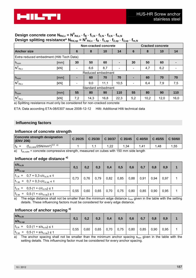
Design concrete cone NRd,c = N0Rd,c fB f1,N f2,N f3,N fre,N
Design splitting resistance* NRd,sp = N0Rd,c fB f1,sp f2,sp f3,sp fre,N
Non-cracked concrete Cracked concrete
Anchor size 6 8 10 14 6 8 10 14
Extra reduced embedment (Hilti Tech Data)
hnom [mm] 30 50 60 - 30 50 60 -
N0Rd,c [kN] - 6,6 8,7 - - 4,7 6,2 -
Reduced embedment
hnom [mm] - 60 70 70 - 60 70 70
N0Rd,c [kN] - 9,0 11,1 10,5 - 6,4 7,9 7,5
Standard embedment
hnom [mm] 55 80 90 110 55 80 90 110
N0Rd,c [kN] 7,2 14,3 16,8 22,3 5,2 10,2 12,0 16,0
a) Splitting resistance must only be considered for non-cracked concrete
ETA: Data according ETA-08/0307 issue 2008-12-12 Hilti: Additional Hilti technical data
Influencing factors
Influence of concrete strengthConcrete strength designation(ENV 206) C 20/25 C 25/30 C 30/37 C 35/45 C 40/50 C 45/55 C 50/60
fB = (fck,cube/25N/mm²)0,5 a) 1 1,1 1,22 1,34 1,41 1,48 1,55
a) fck,cube = concrete compressive strength, measured on cubes with 150 mm side length
Influence of edge distance a)
c/ccr,N0,1 0,2 0,3 0,4 0,5 0,6 0,7 0,8 0,9 1
c/ccr,sp
f1,N = 0,7 + 0,3 c/ccr,N0,73 0,76 0,79 0,82 0,85 0,88 0,91 0,94 0,97 1
f1,sp = 0,7 + 0,3 c/ccr,sp
f2,N = 0,5 (1 + c/ccr,N0,55 0,60 0,65 0,70 0,75 0,80 0,85 0,90 0,95 1
f2,sp = 0,5 (1 + c/ccr,sp
a) The edge distance shall not be smaller than the minimum edge distance cmin given in the table with the setting details. These influencing factors must be considered for every edge distance.
Influence of anchor spacing a)
s/scr,N0,1 0,2 0,3 0,4 0,5 0,6 0,7 0,8 0,9 1
s/scr,sp
f3,N = 0,5 (1 + s/scr,N0,55 0,60 0,65 0,70 0,75 0,80 0,85 0,90 0,95 1
f3,sp = 0,5 (1 + s/scr,sp
a) The anchor spacing shall not be smaller than the minimum anchor spacing smin given in the table with the setting details. This influencing factor must be considered for every anchor spacing.
HUS-HR Screw anchorstainless steel
10 / 2012188
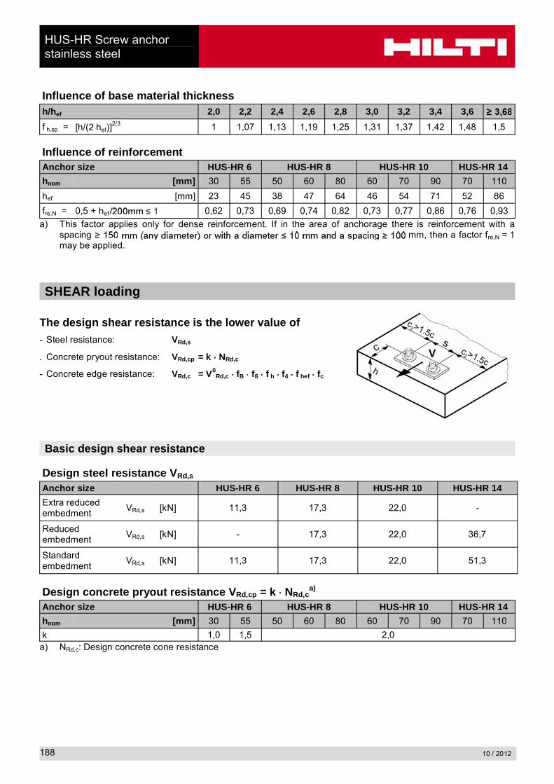
Influence of base material thicknessh/hef 2,0 2,2 2,4 2,6 2,8 3,0 3,2 3,4 3,6
f h,sp = [h/(2 hef)]2/3 1 1,07 1,13 1,19 1,25 1,31 1,37 1,42 1,48 1,5
Influence of reinforcementAnchor size HUS-HR 6 HUS-HR 8 HUS-HR 10 HUS-HR 14
hnom [mm] 30 55 50 60 80 60 70 90 70 110
hef [mm] 23 45 38 47 64 46 54 71 52 86
fre,N = 0,5 + hef 0,62 0,73 0,69 0,74 0,82 0,73 0,77 0,86 0,76 0,93
a) This factor applies only for dense reinforcement. If in the area of anchorage there is reinforcement with a spacing mm, then a factor fre,N = 1may be applied.
SHEAR loading
The design shear resistance is the lower value of- Steel resistance: VRd,s
- Concrete pryout resistance: VRd,cp = k NRd,c
- Concrete edge resistance: VRd,c = V0Rd,c fB fß f h f4 f hef fc
Basic design shear resistance
Design steel resistance VRd,s
Anchor size HUS-HR 6 HUS-HR 8 HUS-HR 10 HUS-HR 14
Extra reduced embedment
VRd,s [kN] 11,3 17,3 22,0 -
Reduced embedment
VRd,s [kN] - 17,3 22,0 36,7
Standard embedment
VRd,s [kN] 11,3 17,3 22,0 51,3
Design concrete pryout resistance VRd,cp = k NRd,ca)
Anchor size HUS-HR 6 HUS-HR 8 HUS-HR 10 HUS-HR 14
hnom [mm] 30 55 50 60 80 60 70 90 70 110
k 1,0 1,5 2,0a) NRd,c: Design concrete cone resistance

HUS-HR Screw anchorstainless steel
10 / 2012 189
Design concrete edge resistance VRd,c = V0Rd,c fB fß f h f4 f hef fc
Non-cracked concrete Cracked concrete
Anchor size HUS-HR � � �� �� � � �� ��
Extra reduced embedment (Hilti Tech Data)
hnom [mm] 30 50 60 - 30 50 60 -
V0Rd,c [kN] - 5,9 8,6 - - 4,2 6,1 -
Reduced embedment
hnom [mm] - 60 70 70 - 60 70 70
V0Rd,c [kN] - 5,9 8,6 15 - 4,2 6,1 10,6
Standard embedment
hnom [mm] 55 80 90 110 55 80 90 110
V0Rd,c [kN] 3,6 5,9 8,6 15,1 2,6 4,2 6,1 10,7
Influencing factors
Influence of concrete strengthConcrete strength designation(ENV 206) C 20/25 C 25/30 C 30/37 C 35/45 C 40/50 C 45/55 C 50/60
fB = (fck,cube/25N/mm²)0,5 a) 1 1,1 1,22 1,34 1,41 1,48 1,55
a) fck,cube = concrete compressive strength, measured on cubes with 150 mm side length
Influence of angle between load applied and the direction perpendicular to the free edgeAngle ß 0° 10° 20° 30° 40° 50° 60° 70° 80° 90°
2cos
1
V
f1 1,01 1,05 1,13 1,24 1,40 1,64 1,97 2,32 2,50
Influence of base material thicknessh/c 0,15 0,3 0,45 0,6 0,75 0,9 1,05 1,2 1,35
f h = {h/(1,5 c)} 1/2 0,32 0,45 0,55 0,63 0,71 0,77 0,84 0,89 0,95 1,00
HUS-HR Screw anchorstainless steel
10 / 2012190
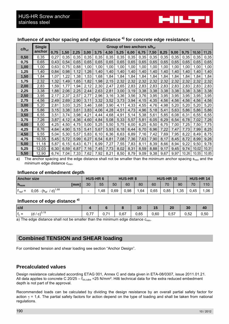
Influence of anchor spacing and edge distance a) for concrete edge resistance: f4
c/hefSingle anchor
Group of two anchors s/hef
0,75 1,50 2,25 3,00 3,75 4,50 5,25 6,00 6,75 7,50 8,25 9,00 9,75 ����� �����0,50 0,35 0,27 0,35 0,35 0,35 0,35 0,35 0,35 0,35 0,35 0,35 0,35 0,35 0,35 0,35 0,350,75 0,65 0,43 0,54 0,65 0,65 0,65 0,65 0,65 0,65 0,65 0,65 0,65 0,65 0,65 0,65 0,651,00 1,00 0,63 0,75 0,88 1,00 1,00 1,00 1,00 1,00 1,00 1,00 1,00 1,00 1,00 1,00 1,001,25 1,40 0,84 0,98 1,12 1,26 1,40 1,40 1,40 1,40 1,40 1,40 1,40 1,40 1,40 1,40 1,401,50 1,84 1,07 1,22 1,38 1,53 1,68 1,84 1,84 1,84 1,84 1,84 1,84 1,84 1,84 1,84 1,841,75 2,32 1,32 1,49 1,65 1,82 1,98 2,15 2,32 2,32 2,32 2,32 2,32 2,32 2,32 2,32 2,322,00 2,83 1,59 1,77 1,94 2,12 2,30 2,47 2,65 2,83 2,83 2,83 2,83 2,83 2,83 2,83 2,832,25 3,38 1,88 2,06 2,25 2,44 2,63 2,81 3,00 3,19 3,38 3,38 3,38 3,38 3,38 3,38 3,382,50 3,95 2,17 2,37 2,57 2,77 2,96 3,16 3,36 3,56 3,76 3,95 3,95 3,95 3,95 3,95 3,952,75 4,56 2,49 2,69 2,90 3,11 3,32 3,52 3,73 3,94 4,15 4,35 4,56 4,56 4,56 4,56 4,563,00 5,20 2,81 3,03 3,25 3,46 3,68 3,90 4,11 4,33 4,55 4,76 4,98 5,20 5,20 5,20 5,203,25 5,86 3,15 3,38 3,61 3,83 4,06 4,28 4,51 4,73 4,96 5,18 5,41 5,63 5,86 5,86 5,863,50 6,55 3,51 3,74 3,98 4,21 4,44 4,68 4,91 5,14 5,38 5,61 5,85 6,08 6,31 6,55 6,553,75 7,26 3,87 4,12 4,36 4,60 4,84 5,08 5,33 5,57 5,81 6,05 6,29 6,54 6,78 7,02 7,264,00 8,00 4,25 4,50 4,75 5,00 5,25 5,50 5,75 6,00 6,25 6,50 6,75 7,00 7,25 7,50 7,754,25 8,76 4,64 4,90 5,15 5,41 5,67 5,93 6,18 6,44 6,70 6,96 7,22 7,47 7,73 7,99 8,254,50 9,55 5,04 5,30 5,57 5,83 6,10 6,36 6,63 6,89 7,16 7,42 7,69 7,95 8,22 8,49 8,754,75 10,35 5,45 5,72 5,99 6,27 6,54 6,81 7,08 7,36 7,63 7,90 8,17 8,45 8,72 8,99 9,265,00 11,18 5,87 6,15 6,43 6,71 6,99 7,27 7,55 7,83 8,11 8,39 8,66 8,94 9,22 9,50 9,785,25 12,03 6,30 6,59 6,87 7,16 7,45 7,73 8,02 8,31 8,59 8,88 9,17 9,45 9,74 10,02 10,315,50 12,90 6,74 7,04 7,33 7,62 7,92 8,21 8,50 8,79 9,09 9,38 9,67 9,97 10,26 10,55 10,85
a) The anchor spacing and the edge distance shall not be smaller than the minimum anchor spacing smin and the minimum edge distance cmin.
Influence of embedment depthAnchor size HUS-HR 6 HUS-HR 8 HUS-HR 10 HUS-HR 14
hnom [mm] 30 55 50 60 80 60 70 90 70 110
f hef = 0,05 (hef / d)1,68 - 1,48 0,69 0,98 1,64 0,65 0,85 1,35 0,45 1,06
Influence of edge distance a)
c/d 4 6 8 10 15 20 30 40
fc = (d / c)0,19 0,77 0,71 0,67 0,65 0,60 0,57 0,52 0,50
a) The edge distance shall not be smaller than the minimum edge distance cmin.
Combined TENSION and SHEAR loading
For combined tension and shear loading see section “Anchor Design”.
Precalculated valuesDesign resistance calculated according ETAG 001, Annex C and data given in ETA-08/0307, issue 2011.01.21.All data applies to concrete C 20/25 – fck,cube =25 N/mm². Hilti technical data for the extra reduced embedment depth is not part of the approval.
Recommended loads can be calculated by dividing the design resistance by an overall partial safety factor for action = 1,4. The partial safety factors for action depend on the type of loading and shall be taken from national regulations.
HUS-HR Screw anchorstainless steel
10 / 2012 191
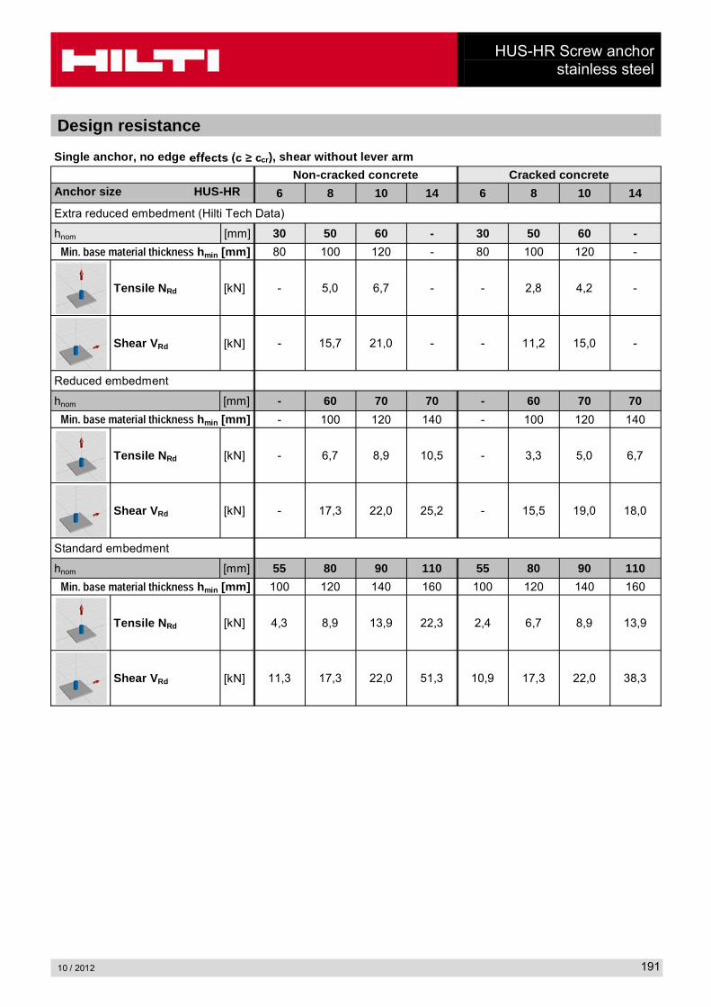
Design resistance
Single anchor, no edge cr), shear without lever arm
Non-cracked concrete Cracked concreteAnchor size HUS-HR 6 8 10 14 6 8 10 14
Extra reduced embedment (Hilti Tech Data)
hnom [mm] 30 50 60 - 30 50 60 -
���������������������������� hmin [mm] 80 100 120 - 80 100 120 -
Tensile NRd [kN] - 5,0 6,7 - - 2,8 4,2 -
Shear VRd [kN] - 15,7 21,0 - - 11,2 15,0 -
Reduced embedment
hnom [mm] - 60 70 70 - 60 70 70
���������������������������� hmin [mm] - 100 120 140 - 100 120 140
Tensile NRd [kN] - 6,7 8,9 10,5 - 3,3 5,0 6,7
Shear VRd [kN] - 17,3 22,0 25,2 - 15,5 19,0 18,0
Standard embedment
hnom [mm] 55 80 90 110 55 80 90 110
���������������������������� hmin [mm] 100 120 140 160 100 120 140 160
Tensile NRd [kN] 4,3 8,9 13,9 22,3 2,4 6,7 8,9 13,9
Shear VRd [kN] 11,3 17,3 22,0 51,3 10,9 17,3 22,0 38,3

HUS-HR Screw anchorstainless steel
10 / 2012192
Single anchor, min. edge distance (c = cmin), shear without lever arm
Non-cracked concrete Cracked concreteAnchor size HUS-HR 6 8 10 14 6 8 10 14
Extra reduced embedment (Hilti Tech Data)
hnom [mm] 30 50 60 - 30 50 60 -
���������������������������� hmin [mm] 80 100 120 - 80 100 120 -
Min. edge distance cmin [mm] 40 45 50 - 40 45 50 -
Tensile NRd [kN] - 5,0 6,7 - - 2,8 4,2 -
Shear VRd [kN] - 3,8 4,7 - - 2,7 3,3 -
Reduced embedment
hnom [mm] - 60 70 70 - 60 70 70
���������������������������� hmin [mm] - 100 120 140 - 100 120 140
Min. edge distance cmin [mm] - 45 50 50 - 45 50 50
Tensile NRd [kN] - 6,6 8,0 7,7 - 3,3 5,0 4,9
Shear VRd [kN] - 3,9 4,8 5,0 - 2,8 3,4 3,6
Standard embedment
hnom [mm] 55 80 90 110 55 80 90 110
���������������������������� hmin [mm] 100 120 140 160 100 120 140 160
Min. edge distance cmin [mm] 40 50 50 60 40 50 50 60
Tensile NRd [kN] 4,3 8,9 10,4 13,8 2,4 6,7 6,8 9,0
Shear VRd [kN] 3,2 4,8 5,1 7,1 2,2 3,4 3,6 5,0
HUS-HR Screw anchorstainless steel
10 / 2012 193
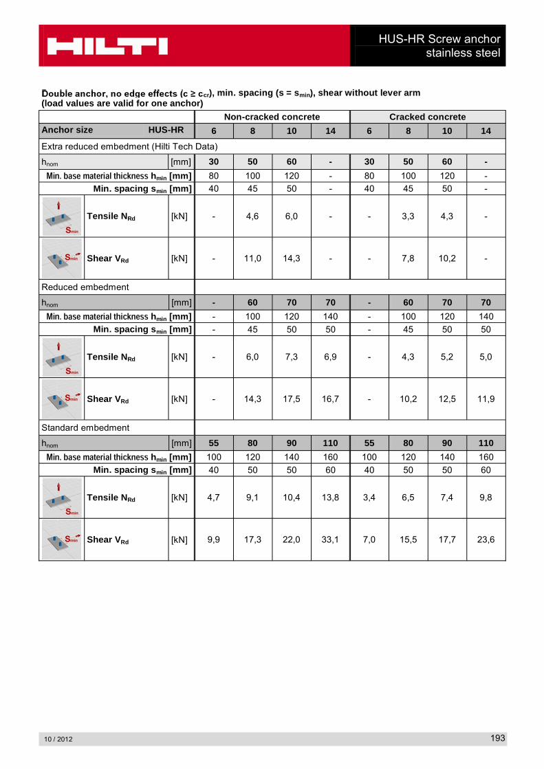
cr), min. spacing (s = smin), shear without lever arm(load values are valid for one anchor)
Non-cracked concrete Cracked concreteAnchor size HUS-HR 6 8 10 14 6 8 10 14
Extra reduced embedment (Hilti Tech Data)
hnom [mm] 30 50 60 - 30 50 60 -
���������������������������� hmin [mm] 80 100 120 - 80 100 120 -
Min. spacing smin [mm] 40 45 50 - 40 45 50 -
Tensile NRd [kN] - 4,6 6,0 - - 3,3 4,3 -
Shear VRd [kN] - 11,0 14,3 - - 7,8 10,2 -
Reduced embedment
hnom [mm] - 60 70 70 - 60 70 70
���������������������������� hmin [mm] - 100 120 140 - 100 120 140
Min. spacing smin [mm] - 45 50 50 - 45 50 50
Tensile NRd [kN] - 6,0 7,3 6,9 - 4,3 5,2 5,0
Shear VRd [kN] - 14,3 17,5 16,7 - 10,2 12,5 11,9
Standard embedment
hnom [mm] 55 80 90 110 55 80 90 110
���������������������������� hmin [mm] 100 120 140 160 100 120 140 160
Min. spacing smin [mm] 40 50 50 60 40 50 50 60
Tensile NRd [kN] 4,7 9,1 10,4 13,8 3,4 6,5 7,4 9,8
Shear VRd [kN] 9,9 17,3 22,0 33,1 7,0 15,5 17,7 23,6

HUS Screw anchorcarbon steel
10 / 2012194
HUS Screw anchor, carbon steelAnchor version Benefits
HUS-A 6
Carbon steel Concrete Screw with hex head
- Quick and easy setting
- Low expansion forces in base materials
- Through fastening
- Removable
- Forged-on washer and hexagon head with no protruding thread
HUS-H 6
Carbon steel Concrete Screw with hex head
HUS-H 8HUS-H 10HUS-H 14
Carbon steel Concrete Screw with hex head
HUS-I 6
Carbon steel Concrete Screw with hex head
HUS-P 6
Carbon steel Concrete Screw with pan head
ConcreteTensile zone
Small edge distance
and spacingSolid brick
Autoclaved aerated concrete
Fire resistance
European Technical Approval
CE conformity
PROFIS Anchor design
software
Approvals / certificates
Description Authority / Laboratory No. / date of issue
European technical approval a)
with fire assessment according TR020DIBt, Berlin ETA-08/0307/ 2011-01-21
Fire test report IBMB, Brunswick UB3574/5146/ 2006-05-20
Fire Assessment report Exova Warringtonfire WF 166402/ 2007-10-26
a) Does not include HUS-H 14
Basic loading data for concrete C20/25All data in this section applies to For details see simplified design method- Correct setting (see setting instruction)- No edge distance and spacing influence- Steel failure- Minimum base material thickness- Concrete C 20/25, fck,cube = 25 N/mm²The following technical data are based on: ETA: Data according ETA-08/0307 issue 2011-01-21
Hilti: Additional Hilti technical data
HUS Screw anchorcarbon steel
10 / 2012 195
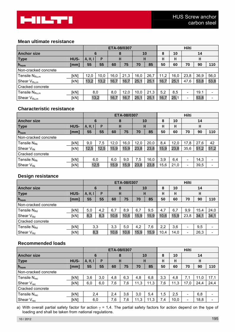
Mean ultimate resistance ETA-08/0307 Hilti
Anchor size 6 8 10 8 10 14Type HUS- ������� � � � � � �
hnom [mm] 55 55 60 75 70 85 50 60 70 90 110Non-cracked concrete
Tensile NRu,m [kN] 12,0 10,0 16,0 21,3 16,0 26,7 11,2 16,0 23,8 36,9 56,0
Shear VRu,m [kN] 13,2 13,2 16,7 16,7 25,1 25,1 16,7 25,1 47,6 53,8 53,8
Cracked concrete
Tensile NRu,m [kN] 8,0 8,0 12,0 10,0 21,3 5,2 8,5 - 19.1 -
Shear VRu,m [kN] 13,2 16,7 16,7 25,1 25,1 16,7 25,1 - 53,8 -
Characteristic resistanceETA-08/0307 Hilti
Anchor size 6 8 10 8 10 14Type HUS- ������� � � � � � �
hnom [mm] 55 55 60 75 70 85 50 60 70 90 110Non-cracked concrete
Tensile NRk [kN] 9,0 7,5 12,0 16,0 12,0 20,0 8,4 12,0 17,8 27,6 42
Shear VRk [kN] 12,5 12,5 15,9 15,9 23,8 23,8 15,9 23,8 35,6 51,2 51,2
Cracked concrete
Tensile NRk [kN] 6,0 6,0 9,0 7,5 16,0 3,9 6,4 - 14,3 -Shear VRk [kN] 12,5 15,9 15,9 23,8 23,8 15,6 21,0 - 39,5 -
Design resistanceETA-08/0307 Hilti
Anchor size 6 8 10 8 10 14Type HUS- ������� � � � � � �
hnom [mm] 55 55 60 75 70 85 50 60 70 90 110Non-cracked concrete
Tensile NRd [kN] 5,0 4,2 6,7 8,9 6,7 9,5 4,7 6,7 9,9 15,4 24,0
Shear VRd [kN] 8,3 8,3 10,6 10,6 15,9 15,9 10,6 15,9 23,8 34,1 34,1
Cracked concrete
Tensile NRd [kN] 3,3 3,3 5,0 4,2 7,6 2,2 3,6 - 9,5 -
Shear VRd [kN] 8,3 10,6 10,6 15,9 15,9 10,4 14,0 - 26,3 -
Recommended loadsETA-08/0307 Hilti
Anchor size 6 8 10 8 10 14Type HUS- ������� � � � � � �
hnom [mm] 55 55 60 75 70 85 50 60 70 90 110Non-cracked concrete
Tensile Nrec [kN] 3,6 3,0 4,8 6,3 4,8 6,8 3,3 4,8 7,1 11,0 17,1
Shear Vrec [kN] 6,0 6,0 7,6 7,6 11,3 11,3 7,6 11,3 17,0 24,4 24,4
Cracked concrete
Tensile Nrec [kN] 2,4 2,4 3,6 3,0 5,4 1,5 2,5 - 6,8 -
Shear Vrec [kN] 6,0 7,6 7,6 11,3 11,3 7,4 10,0 - 18,8 -
a) With overall partial safety factor for action = 1,4. The partial safety factors for action depend on the type of loading and shall be taken from national regulations.
HUS Screw anchorcarbon steel
10 / 2012196
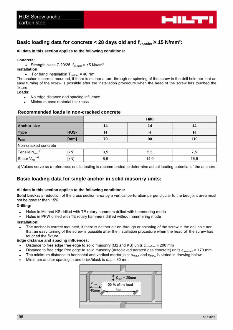
Basic loading data for concrete < 28 days old and fck,cube 15 N/mm²:
All data in this section applies to the following conditions:
Concrete:Strength class C 20/25, fck,cube
Installation:For hand installation Tinst,rec = 40 Nm
The anchor is correct mounted, if there is neither a turn-through or spinning of the screw in the drill hole nor that an easy turning of the screw is possible after the installation procedure when the head of the screw has touched the fixture.Loads:
No edge distance and spacing influenceMinimum base material thickness
Recommended loads in non-cracked concreteHilti
Anchor size 14 14 14
Type HUS- H H H
hnom [mm] 70 90 110
Non-cracked concrete
Tensile Nreca) [kN] 3,5 5,5 7,5
Shear Vreca) [kN] 6,6 14,0 16,5
a) Values serve as a reference, onsite testing is recommended to determine actual loading potential of the anchors
Basic loading data for single anchor in solid masonry units:
All data in this section applies to the following conditions:Solid bricks: a reduction of the cross section area by a vertical perforation perpendicular to the bed joint area must not be greater than 15%
Drilling:
Holes in Mz and KS drilled with TE rotary hammers drilled with hammering modeHoles in PPW drilled with TE rotary hammers drilled without hammering mode
Installation:The anchor is correct mounted, if there is neither a turn-through or spinning of the screw in the drill hole nor that an easy turning of the screw is possible after the installation procedure when the head of the screw has touched the fixture
Edge distance and spacing influences:Distance to free edge free edge to solid masonry (Mz and KS) units cmin,free 200 mmDistance to free edge free edge to solid masonry (autoclaved aerated gas concrete) units cmin,free 170 mmThe minimum distance to horizontal and vertical mortar joint cmin,h and cmin,v is stated in drawing belowMinimum anchor spacing in one brick/block is smin = 80 mm

HUS Screw anchorcarbon steel
10 / 2012 197
Recommended loadsHilti
Base material
Anchor size 6 8 10
Type HUS- A, H, I, P H H
hnom [mm] 55 60 70
Compressive strength class [N/mm²]
Freca) [kN]
Tensile and Shear
Solid clay brick
Mz 2,0-2DFDIN V 105-100 / EN 771-1LxWxH [mm]: 240x115x113hmin [mm]: 115
0,6 0,8 1,0
0,7 0,9 1,2
0,8 1,0 1,3
0,9 1,2 1,5
0,9 1,3 1,7
Solid sand-lime brick
KS 2,0-2DFDIN V 106-100 / EN 771-2LxWxH [mm]: 240x115x113
hmin [mm]: 115
0,8 1,0 1,1
0,9 1,1 1,2
1,0 1,2 1,3
1,1 1,3 1,5
1,2 1,5 1,7
Aerated concrete
PPW -0,65DIN 4165/ EN 771-4
LxWxH [mm]: 499x240x249
hmin [mm]: 240
6 0,4 0,5 1,3
a) Characteristic resistance for tension, shear or combined tension and shear loading.The characteristic resistance is valid for single anchor or for a group of two or four anchors with a spacing equal or larger than the minimum spacing smin according to specification.
Load values:
The technical data for the HUS-H anchors are reference loads for MZ 12 2,0-2DF, KS 12 2,0-2DF and PPW 6-0,65.The load Values are valid for non-structural applications.Due to the natural variation of stone solid bricks, on site anchor testing is recommended to validate technical data.The HUS-H anchor was installed and tested in the centre area of solid bricks as shown considering minimal edge and space distances.The HUS-H anchor was not tested in the mortar joint between solid bricks or in hollow bricks; however a load reduction is expected.For brick walls where anchor position in brick can not be determined, 100% anchor testing is recommended.

HUS Screw anchorcarbon steel
10 / 2012198
Limitations of loads:
All data is for redundant fastening for non structural applicationsPlaster, graveling, lining or leveling courses are regarded as non-bearing and may not be taken into account for the calculation of embedment depth.The decisive resistance to tension loads is the lower value of Nrec (brick breakout, pull out) and Nmax,pb (pull out of one brick).
Pull out of one brick:
The allowable load of an anchor or a group of anchors in case of single brick pull out, Nmax,pb [kN], is given in the following tables:
Clay bricks: All other brick types:
Nmax,pb
[kN]
brick breadth bbrick [mm] Nmax,pb
[kN]
brick breadth bbrick [mm]
80 120 200 240 300 360 80 120 200 240 300 360
brick length
lbrick
[mm]
240 1,1 1,6 2,7 3,3 4,1 4,9 brick length
lbrick
[mm]
240 0,8 1,2 2,1 2,5 3,1 3,7
300 1,4 2,1 3,4 4,1 5,1 6,2 300 1,0 1,5 2,6 3,1 3,9 4,6
500 2,3 3,4 5,7 6,9 8,6 10,3 500 1,7 2,6 4,3 5,1 6,4 7,7
Nmax,pb = resistance for pull out of one bricklbrick = length of the brick bbrick = breadth of the brick
Materials
Mechanical propertiesAnchor size 6 8 10 14Type HUS- A, H, I, P H H H
Nominal tensile strength fuk [N/mm²] 930 950 1000 770
Yield strength fyk [N/mm²] 750 855 900 700
Stressed cross-section As [mm²] 26,9 39,0 55,4 143,1
Moment of resistance W [mm³] 19,6 34,4 58,2 191,7
Design bending resistance MRd,s [Nm] 21,9 26,1 46,5 118
lbrick bbrickNmax,pb

HUS Screw anchorcarbon steel
10 / 2012 199
Material quality
Part Designation Material
Screw anchor
HUS-AHUS-HHUS-IHUS-PHUS-HHUS-HHUS-H
666681014
Carbon Steel,
Head configuration
HUS-A 6External threadM8 or M10
Circle mark with d = 2,5 mm for hnom = 55 mm
HUS-H 6Hex head
HUS-I 6Internal threadsM8 and M10
Two circle marks with d = 0,8 mm for hnom = 55 mm
HUS-P 6Pan head
HUS-H 8HUS-H 10HUS-H 14
Hex head
dsdk
ls

HUS Screw anchorcarbon steel
10 / 2012200
Anchor dimensions:
DimensionsAnchor size 6 8 10 14
Type HUS- A H I P H H H
Nominal length lS [mm] 55 60..120 55 60..80 65..150 75..280 80..160
Outer diameter of thread
dS [mm] 7,85 10,1 12,3 16,55
Core diameter dk [mm] 5,85 7,1 8,4 12,6
Setting:
Recommended installation equipmentAnchor Size 6 8 10 14
Type HUS- A I H P H H H
hnom [mm] 55 50 60 70 60 70 85 70 90 110
Rotary hammer TE 2 - TE 7 TE 2 - TE 30
drill bit for concrete, solid clay bricksolid sand-lime brick
TE -CX 6 TE -CX 8 TE -CX 10 TE -CX 14
drill bit for aerated concrete TE -CX 5 TE -CX 6 TE -CX 8 -
Socket wrench insertS-NSD 13
1/2 L- S-NSD 13 1/2 L S-NSD 15 1/2 S-NSD 21 1/2
TORX - TXI 30 - - -
Setting toolSIW/ SID 121SIW/ SID 144
TKI 2500
SIW 22T-ASI 100
Setting details for concrete from C20/25 to C50/60Anchor size 6 8 10 14
Type HUS- A I H P H H H
hnom [mm] 55 50 60 70 60 70 85 70 90 ���
Nominal diameter of drill bit d0 [mm] 6 8 10 14
Cutting diameter of drill bit dcut [mm] 6,4 8,45 10,45 14,50
Clearance hole diameter df [mm] 9 12 14 18
Depth of drill hole in floor/ wall position
h1 [mm] hnom+10 mmhnom
+10 mmhnom
+10 mmhnom
+10 mmDepth of drill hole in ceiling position
h1 [mm] hnom+3 mm
Thickness of fixture tfix [mm] ls - hnom
Max. installation torque for hand setting
max. Tinst [Nm] 25 35 35 45 45 45 55 65 (40)a)
Impact screw driver for machine settingSIW/SID 121,144
TKI 2500SIW 22T-A
SI 100SIW 22T-A
SI 100 b)
a) For concrete < 28 days old and fck,cubeb) For concrete < 28 days old and fck,cube ² only hand setting is recommended
HUS Screw anchorcarbon steel
10 / 2012 201
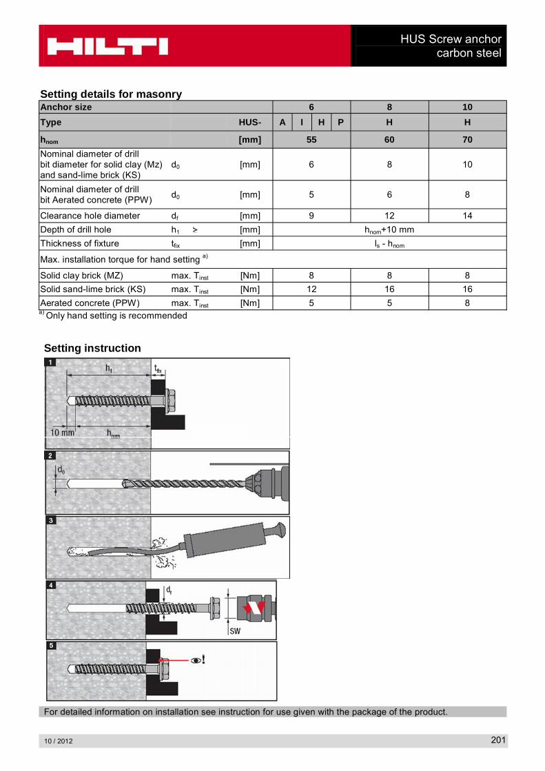
Setting details for masonryAnchor size 6 8 10
Type HUS- A I H P H H
hnom [mm] 55 60 70
Nominal diameter of drill bit diameter for solid clay (Mz)and sand-lime brick (KS)
d0 [mm] 6 8 10
Nominal diameter of drill bit Aerated concrete (PPW)
d0 [mm] 5 6 8
Clearance hole diameter df [mm] 9 12 14
Depth of drill hole h1 [mm] hnom+10 mm
Thickness of fixture tfix [mm] ls - hnom
Max. installation torque for hand setting a)
Solid clay brick (MZ) max. Tinst [Nm] 8 8 8
Solid sand-lime brick (KS) max. Tinst [Nm] 12 16 16
Aerated concrete (PPW) max. Tinst [Nm] 5 5 8a) Only hand setting is recommended
Setting instruction
For detailed information on installation see instruction for use given with the package of the product.
HUS Screw anchorcarbon steel
10 / 2012202
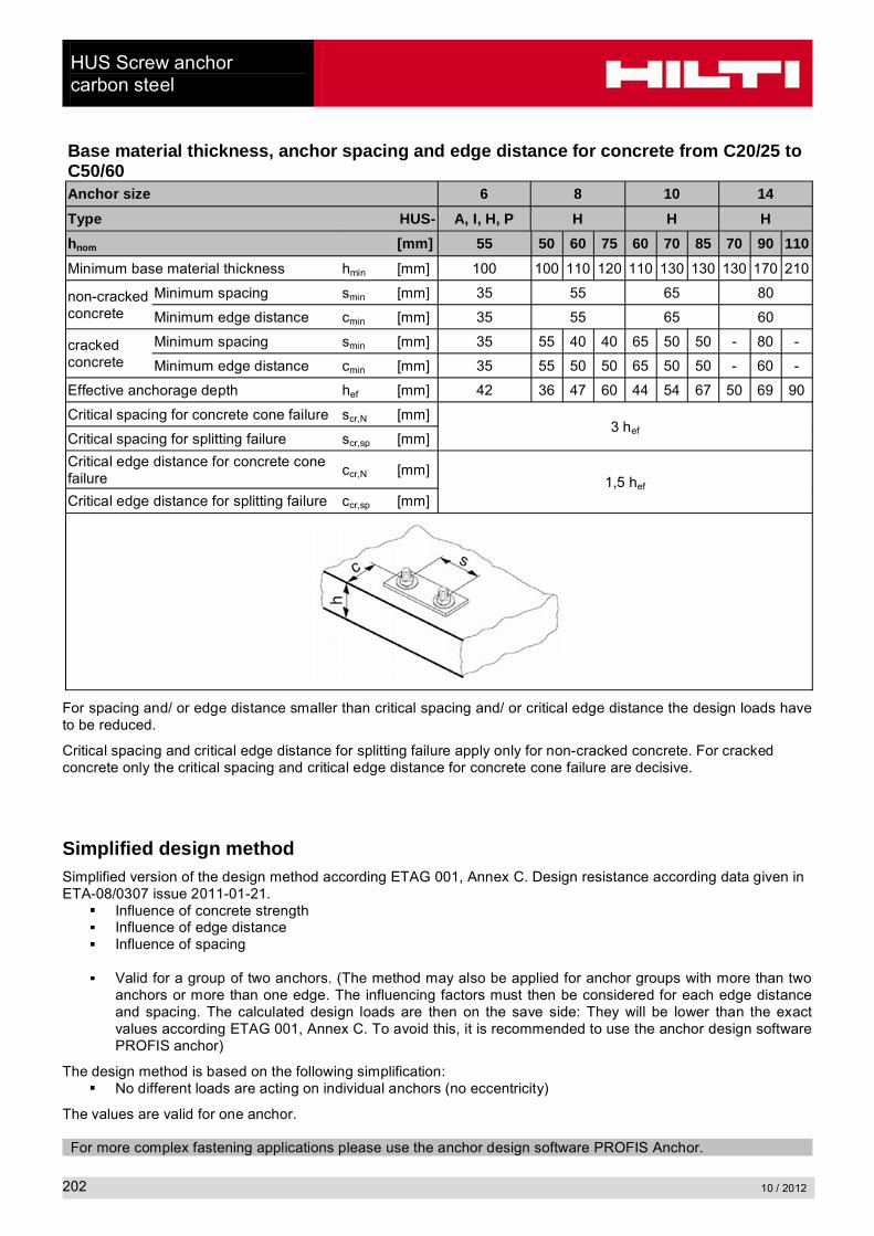
Base material thickness, anchor spacing and edge distance for concrete from C20/25 to C50/60Anchor size 6 8 10 14
Type HUS- A, I, H, P H H H
hnom [mm] 55 50 60 75 60 70 85 70 90 110
Minimum base material thickness hmin [mm] 100 100 110 120 110 130 130 130 170 210
non-cracked concrete
Minimum spacing smin [mm] 35 55 65 80
Minimum edge distance cmin [mm] 35 55 65 60
cracked concrete
Minimum spacing smin [mm] 35 55 40 40 65 50 50 - 80 -
Minimum edge distance cmin [mm] 35 55 50 50 65 50 50 - 60 -
Effective anchorage depth hef [mm] 42 36 47 60 44 54 67 50 69 90
Critical spacing for concrete cone failure scr,N [mm]3 hef
Critical spacing for splitting failure scr,sp [mm]
Critical edge distance for concrete cone failure
ccr,N [mm]1,5 hef
Critical edge distance for splitting failure ccr,sp [mm]
For spacing and/ or edge distance smaller than critical spacing and/ or critical edge distance the design loads have to be reduced.
Critical spacing and critical edge distance for splitting failure apply only for non-cracked concrete. For cracked concrete only the critical spacing and critical edge distance for concrete cone failure are decisive.
Simplified design methodSimplified version of the design method according ETAG 001, Annex C. Design resistance according data given in ETA-08/0307 issue 2011-01-21.
Influence of concrete strengthInfluence of edge distanceInfluence of spacing
Valid for a group of two anchors. (The method may also be applied for anchor groups with more than two anchors or more than one edge. The influencing factors must then be considered for each edge distance and spacing. The calculated design loads are then on the save side: They will be lower than the exact values according ETAG 001, Annex C. To avoid this, it is recommended to use the anchor design software PROFIS anchor)
The design method is based on the following simplification:No different loads are acting on individual anchors (no eccentricity)
The values are valid for one anchor.
For more complex fastening applications please use the anchor design software PROFIS Anchor.
HUS Screw anchorcarbon steel
10 / 2012 203
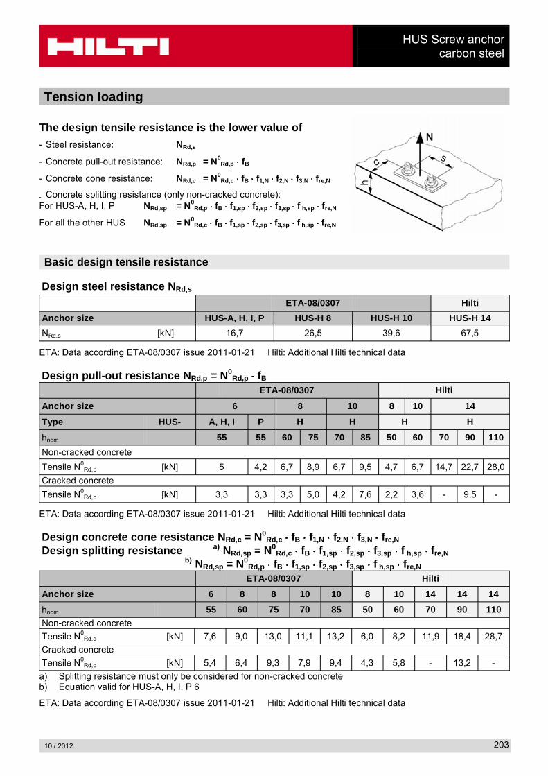
Tension loading
The design tensile resistance is the lower value of- Steel resistance: NRd,s
- Concrete pull-out resistance: NRd,p = N0Rd,p fB
- Concrete cone resistance: NRd,c = N0Rd,c fB f1,N f2,N f3,N fre,N
- Concrete splitting resistance (only non-cracked concrete):For HUS-A, H, I, P NRd,sp = N0
Rd,p fB f1,sp f2,sp f3,sp f h,sp fre,N
For all the other HUS NRd,sp = N0Rd,c fB f1,sp f2,sp f3,sp f h,sp fre,N
Basic design tensile resistance
Design steel resistance NRd,s
ETA-08/0307 Hilti
Anchor size HUS-A, H, I, P HUS-H 8 HUS-H 10 HUS-H 14
NRd,s [kN] 16,7 26,5 39,6 67,5
ETA: Data according ETA-08/0307 issue 2011-01-21 Hilti: Additional Hilti technical data
Design pull-out resistance NRd,p = N0Rd,p fB
ETA-08/0307 Hilti
Anchor size 6 8 10 8 10 14
Type HUS- A, H, I P H H H H
hnom 55 55 60 75 70 85 50 60 70 90 110
Non-cracked concrete
Tensile N0Rd,p [kN] 5 4,2 6,7 8,9 6,7 9,5 4,7 6,7 14,7 22,7 28,0
Cracked concrete
Tensile N0Rd,p [kN] 3,3 3,3 3,3 5,0 4,2 7,6 2,2 3,6 - 9,5 -
ETA: Data according ETA-08/0307 issue 2011-01-21 Hilti: Additional Hilti technical data
Design concrete cone resistance NRd,c = N0Rd,c fB f1,N f2,N f3,N fre,N
Design splitting resistance a) NRd,sp = N0Rd,c fB f1,sp f2,sp f3,sp f h,sp fre,N
b) NRd,sp = N0Rd,p fB f1,sp f2,sp f3,sp f h,sp fre,N
ETA-08/0307 Hilti
Anchor size 6 8 8 10 10 8 10 14 14 14
hnom 55 60 75 70 85 50 60 70 90 110
Non-cracked concrete
Tensile N0Rd,c [kN] 7,6 9,0 13,0 11,1 13,2 6,0 8,2 11,9 18,4 28,7
Cracked concrete
Tensile N0Rd,c [kN] 5,4 6,4 9,3 7,9 9,4 4,3 5,8 - 13,2 -
a) Splitting resistance must only be considered for non-cracked concreteb) Equation valid for HUS-A, H, I, P 6
ETA: Data according ETA-08/0307 issue 2011-01-21 Hilti: Additional Hilti technical data

HUS Screw anchorcarbon steel
10 / 2012204
Influencing factors
Influence of concrete strengthConcrete strength designation (ENV 206) HUS hnom ������� ������� ������� ������� ������� ������� �������
fB = (fck,cube/25N/mm²)0,5 a)
6 55
1 1,10 1,22 1,34 1,41 1,48 1,558 50...75
10 8514 70...110
fB = (fck,cube/25N/mm²)0,4 a) 10 60...70 1 1,08 1,17 1,27 1,32 1,37 1,42
a) fck,cube = concrete compressive strength, measured on cubes with 150 mm side length
Influence of edge distance a)
c/ccr,N0,1 0,2 0,3 0,4 0,5 0,6 0,7 0,8 0,9 1
c/ccr,sp
f1,N = 0,7 + 0,3 c/ccr,N0,73 0,76 0,79 0,82 0,85 0,88 0,91 0,94 0,97 1
f1,sp = 0,7 + 0,3 c/ccr,sp
f2,N = 0,5 (1 + c/ccr,N0,55 0,60 0,65 0,70 0,75 0,80 0,85 0,90 0,95 1
f2,sp = 0,5 (1 + c/ccr,sp
a) The edge distance shall not be smaller than the minimum edge distance cmin given in the table with the setting details. These influencing factors must be considered for every edge distance.
Influence of anchor spacing a)
s/scr,N0,1 0,2 0,3 0,4 0,5 0,6 0,7 0,8 0,9 1
s/scr,sp
f3,N = 0,5 (1 + s/scr,N0,55 0,60 0,65 0,70 0,75 0,80 0,85 0,90 0,95 1
f3,sp = 0,5 (1 + s/scr,sp
a) The anchor spacing shall not be smaller than the minimum anchor spacing smin given in the table with the setting details. This influencing factor must be considered for every anchor spacing.
Influence of base material thicknessh/hef 2,0 2,2 2,4 2,6 2,8 3,0 3,2 3,4 3,6
f h,sp = [h/(2 hef)]2/3 1 1,07 1,13 1,19 1,25 1,31 1,37 1,42 1,48 1,5
Influence of reinforcementAnchor size 6 8 10 14Type HUS- A, H, I, P H H H
hnom [mm] 55 50 60 75 60 70 85 70 90 110
hef [mm] 42 36 46,9 59,6 44 52,7 66,8 50 67 90
fre,Na) = 0,5 + hef 0,71 0,68 0,73 0,8 0,72 0,76 0,83 0,7 0,84 0,95
a) This factor applies only for dense reinforcement. If in the area of anchorage there is reinforcement with a spacing mm, then a factor fre,N = 1may be applied.
HUS Screw anchorcarbon steel
10 / 2012 205
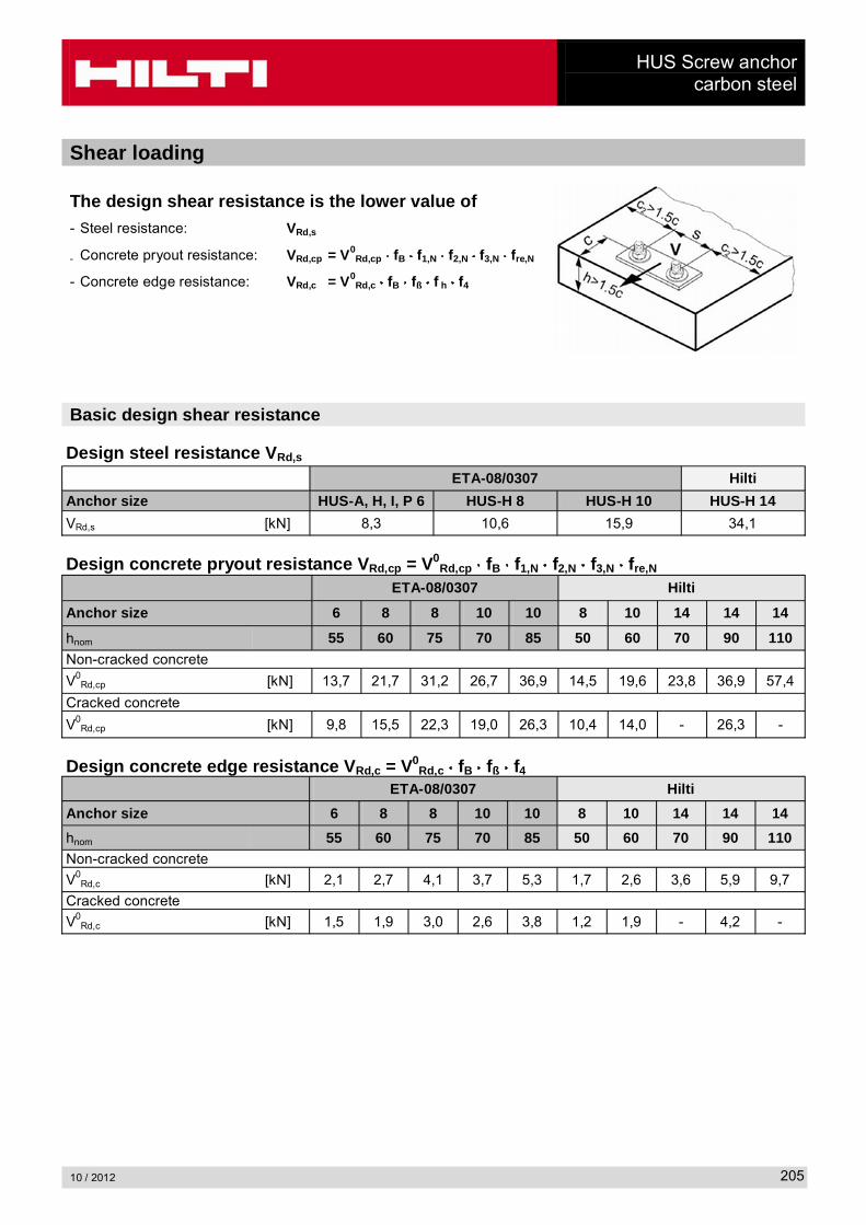
Shear loading
The design shear resistance is the lower value of- Steel resistance: VRd,s
- Concrete pryout resistance: VRd,cp = V0Rd,cp fB f1,N f2,N f3,N fre,N
- Concrete edge resistance: VRd,c = V0Rd,c fB fß f h f4
Basic design shear resistance
Design steel resistance VRd,s
ETA-08/0307 Hilti
Anchor size HUS-A, H, I, P 6 HUS-H 8 HUS-H 10 HUS-H 14
VRd,s [kN] 8,3 10,6 15,9 34,1
Design concrete pryout resistance VRd,cp = V0Rd,cp fB f1,N f2,N f3,N fre,N
ETA-08/0307 Hilti
Anchor size 6 8 8 10 10 8 10 14 14 14
hnom 55 60 75 70 85 50 60 70 90 110
Non-cracked concrete
V0Rd,cp [kN] 13,7 21,7 31,2 26,7 36,9 14,5 19,6 23,8 36,9 57,4
Cracked concrete
V0Rd,cp [kN] 9,8 15,5 22,3 19,0 26,3 10,4 14,0 - 26,3 -
Design concrete edge resistance VRd,c = V0Rd,c fB fß f4
ETA-08/0307 Hilti
Anchor size 6 8 8 10 10 8 10 14 14 14
hnom 55 60 75 70 85 50 60 70 90 110Non-cracked concrete
V0Rd,c [kN] 2,1 2,7 4,1 3,7 5,3 1,7 2,6 3,6 5,9 9,7
Cracked concrete
V0Rd,c [kN] 1,5 1,9 3,0 2,6 3,8 1,2 1,9 - 4,2 -

HUS Screw anchorcarbon steel
10 / 2012206
Influencing factors
Influence of concrete strengthConcrete strength designation (ENV 206) HUS hnom ������� ������� ������� ������� ������� ������� �������
fB = (fck,cube/25N/mm²)0,5 a)
6 55
1 1,10 1,22 1,34 1,41 1,48 1,558 50...75
10 8514 70...110
fB = (fck,cube/25N/mm²)0,4 a) 10 60...70 1 1,08 1,17 1,27 1,32 1,37 1,42
a) fck,cube = concrete compressive strength, measured on cubes with 150 mm side length
Influence of edge distance a)
c/ccr,N 0,1 0,2 0,3 0,4 0,5 0,6 0,7 0,8 0,9 1
f1,N = 0,7 + 0,3 c/ccr,N 0,73 0,76 0,79 0,82 0,85 0,88 0,91 0,94 0,97 1
f2,N = 0,5 (1 + c/ccr,N 0,55 0,60 0,65 0,70 0,75 0,80 0,85 0,90 0,95 1
a) The edge distance shall not be smaller than the minimum edge distance cmin given in the table with the setting details. These influencing factors must be considered for every edge distance.
Influence of anchor spacing a)
s/scr,N 0,1 0,2 0,3 0,4 0,5 0,6 0,7 0,8 0,9 1
f3,N = 0,5 (1 + s/scr,N 0,55 0,60 0,65 0,70 0,75 0,80 0,85 0,90 0,95 1
a) The anchor spacing shall not be smaller than the minimum anchor spacing smin given in the table with the setting details. This influence factor must be considered for every anchor spacing.
Influence of reinforcementAnchor size 6 8 10 14Type HUS- A, H, I, P H H H
hnom [mm] 55 50 60 75 60 70 85 70 90 110
hef [mm] 42 36 46,9 59,6 44 52,7 66,8 50 67 90
fre,Na) = 0,5 + hef 0,71 0,68 0,73 0,8 0,72 0,76 0,83 0,7 0,84 0,95
a) This factor applies only for dense reinforcement. If in the area of anchorage there is reinforcement with a spacing mm, then a factor fre,N = 1may be applied.
Influence of angle between load applied and the direction perpendicular to the free edgeAngle ß 0° - 55° 60° 65° 70° 75° 80° 85° ����� ����
fß 1,00 1,07 1,14 1,23 1,35 1,50 1,71 2,00
Influence of base material thicknessh/c 0,15 0,3 0,45 0,6 0,75 0,9 1,05 1,2 1,35
f h = {h/(1,5 c)} 2/3 0,22 0,34 0,45 0,54 0,63 0,71 0,79 0,86 0,93 1,00
HUS Screw anchorcarbon steel
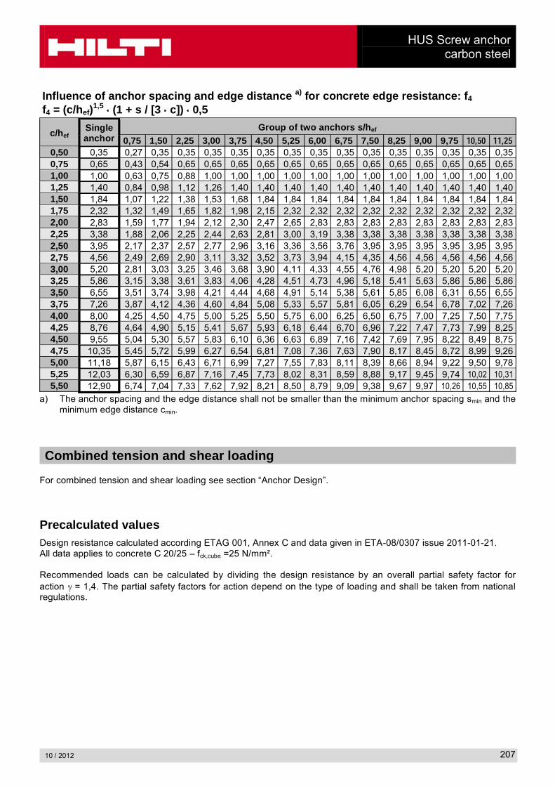
10 / 2012 207
Influence of anchor spacing and edge distance a) for concrete edge resistance: f4
f4 = (c/hef)1,5 (1 + s / [3 c]) 0,5
c/hefSingle anchor
Group of two anchors s/hef
0,75 1,50 2,25 3,00 3,75 4,50 5,25 6,00 6,75 7,50 8,25 9,00 9,75 ����� �����0,50 0,35 0,27 0,35 0,35 0,35 0,35 0,35 0,35 0,35 0,35 0,35 0,35 0,35 0,35 0,35 0,350,75 0,65 0,43 0,54 0,65 0,65 0,65 0,65 0,65 0,65 0,65 0,65 0,65 0,65 0,65 0,65 0,651,00 1,00 0,63 0,75 0,88 1,00 1,00 1,00 1,00 1,00 1,00 1,00 1,00 1,00 1,00 1,00 1,001,25 1,40 0,84 0,98 1,12 1,26 1,40 1,40 1,40 1,40 1,40 1,40 1,40 1,40 1,40 1,40 1,401,50 1,84 1,07 1,22 1,38 1,53 1,68 1,84 1,84 1,84 1,84 1,84 1,84 1,84 1,84 1,84 1,841,75 2,32 1,32 1,49 1,65 1,82 1,98 2,15 2,32 2,32 2,32 2,32 2,32 2,32 2,32 2,32 2,322,00 2,83 1,59 1,77 1,94 2,12 2,30 2,47 2,65 2,83 2,83 2,83 2,83 2,83 2,83 2,83 2,832,25 3,38 1,88 2,06 2,25 2,44 2,63 2,81 3,00 3,19 3,38 3,38 3,38 3,38 3,38 3,38 3,382,50 3,95 2,17 2,37 2,57 2,77 2,96 3,16 3,36 3,56 3,76 3,95 3,95 3,95 3,95 3,95 3,952,75 4,56 2,49 2,69 2,90 3,11 3,32 3,52 3,73 3,94 4,15 4,35 4,56 4,56 4,56 4,56 4,563,00 5,20 2,81 3,03 3,25 3,46 3,68 3,90 4,11 4,33 4,55 4,76 4,98 5,20 5,20 5,20 5,203,25 5,86 3,15 3,38 3,61 3,83 4,06 4,28 4,51 4,73 4,96 5,18 5,41 5,63 5,86 5,86 5,863,50 6,55 3,51 3,74 3,98 4,21 4,44 4,68 4,91 5,14 5,38 5,61 5,85 6,08 6,31 6,55 6,553,75 7,26 3,87 4,12 4,36 4,60 4,84 5,08 5,33 5,57 5,81 6,05 6,29 6,54 6,78 7,02 7,264,00 8,00 4,25 4,50 4,75 5,00 5,25 5,50 5,75 6,00 6,25 6,50 6,75 7,00 7,25 7,50 7,754,25 8,76 4,64 4,90 5,15 5,41 5,67 5,93 6,18 6,44 6,70 6,96 7,22 7,47 7,73 7,99 8,254,50 9,55 5,04 5,30 5,57 5,83 6,10 6,36 6,63 6,89 7,16 7,42 7,69 7,95 8,22 8,49 8,754,75 10,35 5,45 5,72 5,99 6,27 6,54 6,81 7,08 7,36 7,63 7,90 8,17 8,45 8,72 8,99 9,265,00 11,18 5,87 6,15 6,43 6,71 6,99 7,27 7,55 7,83 8,11 8,39 8,66 8,94 9,22 9,50 9,785,25 12,03 6,30 6,59 6,87 7,16 7,45 7,73 8,02 8,31 8,59 8,88 9,17 9,45 9,74 10,02 10,315,50 12,90 6,74 7,04 7,33 7,62 7,92 8,21 8,50 8,79 9,09 9,38 9,67 9,97 10,26 10,55 10,85
a) The anchor spacing and the edge distance shall not be smaller than the minimum anchor spacing smin and the minimum edge distance cmin.
Combined tension and shear loading
For combined tension and shear loading see section “Anchor Design”.
Precalculated valuesDesign resistance calculated according ETAG 001, Annex C and data given in ETA-08/0307 issue 2011-01-21.All data applies to concrete C 20/25 – fck,cube =25 N/mm².
Recommended loads can be calculated by dividing the design resistance by an overall partial safety factor for action = 1,4. The partial safety factors for action depend on the type of loading and shall be taken from national regulations.
HUS Screw anchorcarbon steel
10 / 2012208
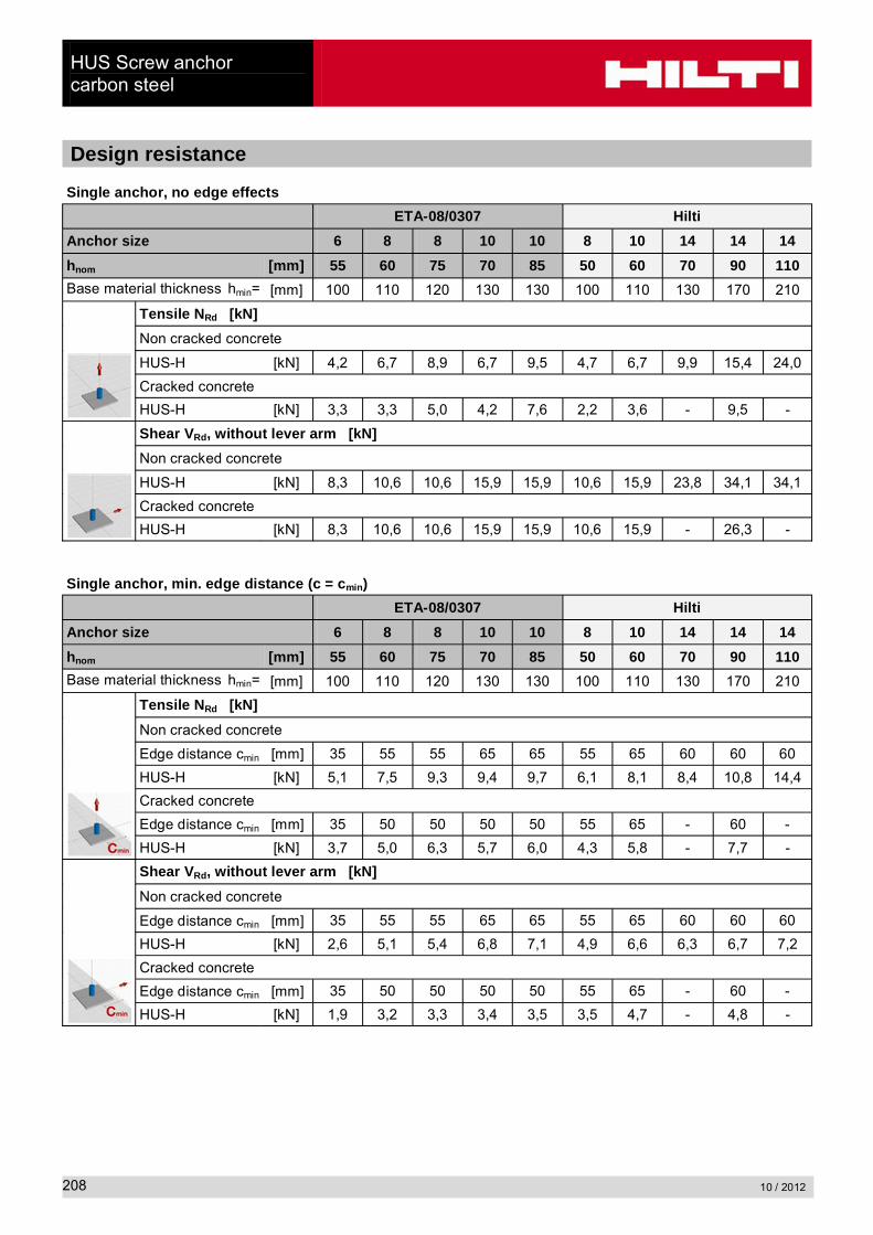
Design resistance
Single anchor, no edge effects
ETA-08/0307 Hilti
Anchor size 6 8 8 10 10 8 10 14 14 14
hnom [mm] 55 60 75 70 85 50 60 70 90 110
Base material thickness hmin= [mm] 100 110 120 130 130 100 110 130 170 210
Tensile NRd [kN]
Non cracked concrete
HUS-H [kN] 4,2 6,7 8,9 6,7 9,5 4,7 6,7 9,9 15,4 24,0
Cracked concrete
HUS-H [kN] 3,3 3,3 5,0 4,2 7,6 2,2 3,6 - 9,5 -
Shear VRd, without lever arm [kN]
Non cracked concrete
HUS-H [kN] 8,3 10,6 10,6 15,9 15,9 10,6 15,9 23,8 34,1 34,1
Cracked concrete
HUS-H [kN] 8,3 10,6 10,6 15,9 15,9 10,6 15,9 - 26,3 -
Single anchor, min. edge distance (c = cmin)
ETA-08/0307 Hilti
Anchor size 6 8 8 10 10 8 10 14 14 14
hnom [mm] 55 60 75 70 85 50 60 70 90 110
Base material thickness hmin= [mm] 100 110 120 130 130 100 110 130 170 210
Tensile NRd [kN]
Non cracked concrete
Edge distance cmin [mm] 35 55 55 65 65 55 65 60 60 60
HUS-H [kN] 5,1 7,5 9,3 9,4 9,7 6,1 8,1 8,4 10,8 14,4
Cracked concrete
Edge distance cmin [mm] 35 50 50 50 50 55 65 - 60 -
HUS-H [kN] 3,7 5,0 6,3 5,7 6,0 4,3 5,8 - 7,7 -
Shear VRd, without lever arm [kN]
Non cracked concrete
Edge distance cmin [mm] 35 55 55 65 65 55 65 60 60 60
HUS-H [kN] 2,6 5,1 5,4 6,8 7,1 4,9 6,6 6,3 6,7 7,2
Cracked concrete
Edge distance cmin [mm] 35 50 50 50 50 55 65 - 60 -
HUS-H [kN] 1,9 3,2 3,3 3,4 3,5 3,5 4,7 - 4,8 -
HUS Screw anchorcarbon steel
10 / 2012 209
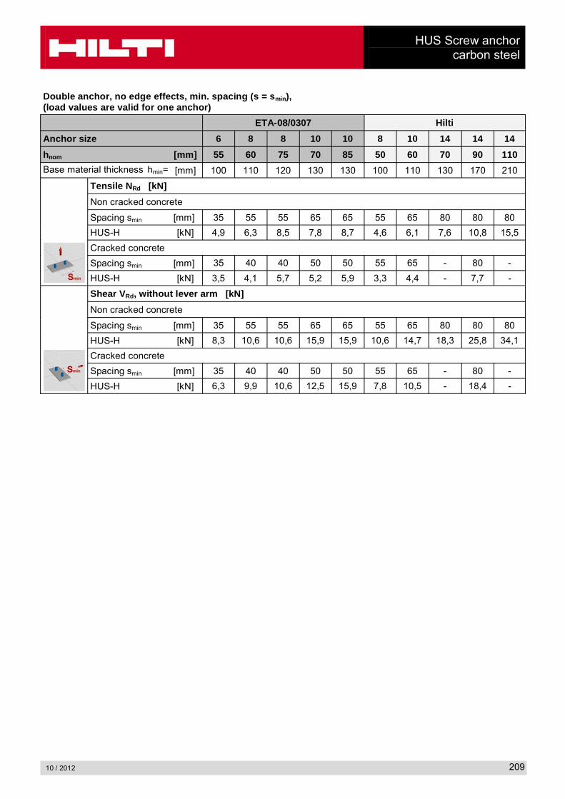
Double anchor, no edge effects, min. spacing (s = smin),(load values are valid for one anchor)
ETA-08/0307 Hilti
Anchor size 6 8 8 10 10 8 10 14 14 14
hnom [mm] 55 60 75 70 85 50 60 70 90 110
Base material thickness hmin= [mm] 100 110 120 130 130 100 110 130 170 210
Tensile NRd [kN]
Non cracked concrete
Spacing smin [mm] 35 55 55 65 65 55 65 80 80 80
HUS-H [kN] 4,9 6,3 8,5 7,8 8,7 4,6 6,1 7,6 10,8 15,5
Cracked concrete
Spacing smin [mm] 35 40 40 50 50 55 65 - 80 -
HUS-H [kN] 3,5 4,1 5,7 5,2 5,9 3,3 4,4 - 7,7 -
Shear VRd, without lever arm [kN]
Non cracked concrete
Spacing smin [mm] 35 55 55 65 65 55 65 80 80 80
HUS-H [kN] 8,3 10,6 10,6 15,9 15,9 10,6 14,7 18,3 25,8 34,1
Cracked concrete
Spacing smin [mm] 35 40 40 50 50 55 65 - 80 -
HUS-H [kN] 6,3 9,9 10,6 12,5 15,9 7,8 10,5 - 18,4 -

HUS 6 Screw anchorRedundant fastening
10 / 2012210
HUS 6 Screw anchor, Redundant fastening
Anchor version Benefits
HUS-A 6
Carbon steel Concrete Screw with hex head
- Quick and easy setting
- Low expansion forces in base materials
- Through fastening
- Removable
- Forged-on washer and hexagon head with no protruding thread
HUS-H 6
Carbon steel Concrete Screw with hex head
HUS-I 6
Carbon steel Concrete Screw with hex head
HUS-P 6
Carbon steel Concrete Screw with pan head
HUS-HR 6Stainless steel Concrete Screw
ConcreteTensilezone
Small edge distance
and spacing
Redundant fastening
Fire resistance
Corrosion Resistance
European Technical Approval
CE conformity
Approvals / certificatesDescription Authority / Laboratory No. / date of issueEuropean technical approval a) DIBt, Berlin ETA-10/0005 / 2011-08-23Fire test report DIBt, Berlin ETA-10/0005 / 2011-08-23
a) Data for HUS-HR 6 with nominal embedment depth = 30 mm for multiple use for non-structural applications(= redundant fastening) are not part of ETA-10/0005 issue 2011-08-23
Basic loading dataAll data in this section applies to For details see Simplified design method- Correct setting (See setting instruction)- No edge distance and spacing influence- Concrete C 20/25, fck,cube = 25 N/mm²
The following technical data are based on:ETA: Data according ETA-05/0005 issue 2011-08-23 Hilti: Additional Hilti technical data
HUS 6 Screw anchorRedundant fastening
10 / 2012 211
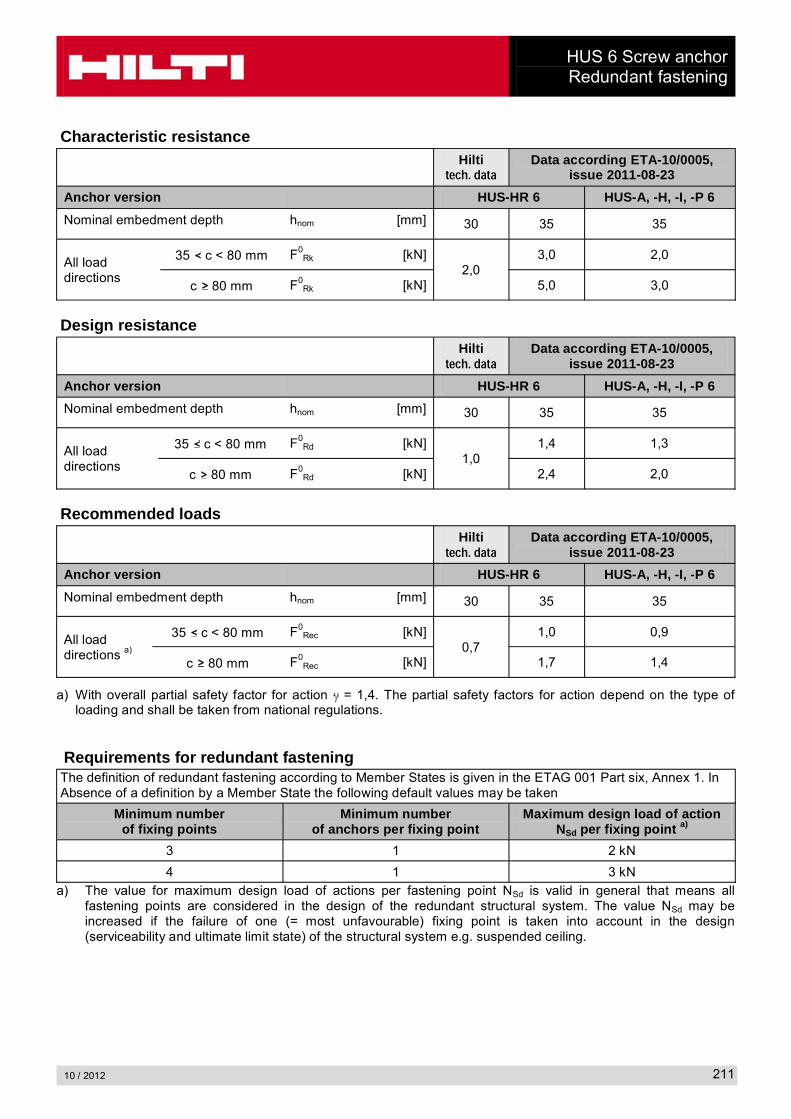
Characteristic resistanceHilti����������
Data according ETA-10/0005, issue 2011-08-23
Anchor version HUS-HR 6 HUS-A, -H, -I, -P 6
Nominal embedment depth hnom [mm] 30 35 35
All load directions
35 c < 80 mm F0Rk [kN]
2,03,0 2,0
c 80 mm F0Rk [kN] 5,0 3,0
Design resistanceHilti����������
Data according ETA-10/0005, issue 2011-08-23
Anchor version HUS-HR 6 HUS-A, -H, -I, -P 6
Nominal embedment depth hnom [mm] 30 35 35
All load directions
35 c < 80 mm F0Rd [kN]
1,01,4 1,3
c 80 mm F0Rd [kN] 2,4 2,0
Recommended loadsHilti����������
Data according ETA-10/0005, issue 2011-08-23
Anchor version HUS-HR 6 HUS-A, -H, -I, -P 6
Nominal embedment depth hnom [mm] 30 35 35
All load directions a)
35 c < 80 mm F0Rec [kN]
0,71,0 0,9
c 80 mm F0Rec [kN] 1,7 1,4
a) With overall partial safety factor for action = 1,4. The partial safety factors for action depend on the type of loading and shall be taken from national regulations.
Requirements for redundant fasteningThe definition of redundant fastening according to Member States is given in the ETAG 001 Part six, Annex 1. In Absence of a definition by a Member State the following default values may be taken
Minimum numberof fixing points
Minimum numberof anchors per fixing point
Maximum design load of action NSd per fixing point a)
3 1 2 kN
4 1 3 kN
a) The value for maximum design load of actions per fastening point NSd is valid in general that means all fastening points are considered in the design of the redundant structural system. The value NSd may be increased if the failure of one (= most unfavourable) fixing point is taken into account in the design (serviceability and ultimate limit state) of the structural system e.g. suspended ceiling.
HUS 6 Screw anchorRedundant fastening
10 / 2012212
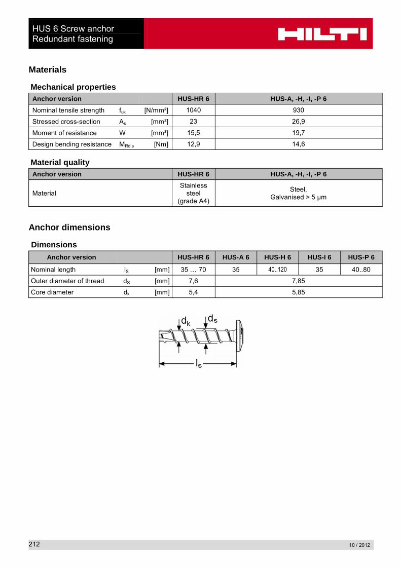
Materials
Mechanical propertiesAnchor version HUS-HR 6 HUS-A, -H, -I, -P 6
Nominal tensile strength fuk [N/mm²] 1040 930
Stressed cross-section As [mm²] 23 26,9
Moment of resistance W [mm³] 15,5 19,7
Design bending resistance MRd,s [Nm] 12,9 14,6
Material qualityAnchor version HUS-HR 6 HUS-A, -H, -I, -P 6
MaterialStainless
steel(grade A4)
Steel,Galvanised 5 µm
Anchor dimensions
Dimensions
Anchor version HUS-HR 6 HUS-A 6 HUS-H 6 HUS-I 6 HUS-P 6
Nominal length lS [mm] 35 … 70 35 40..120 35 40..80
Outer diameter of thread dS [mm] 7,6 7,85
Core diameter dk [mm] 5,4 5,85
HUS 6 Screw anchorRedundant fastening
10 / 2012 213
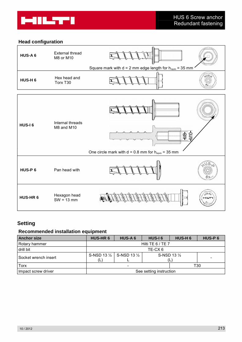
Head configuration
HUS-A 6 External threadM8 or M10
Square mark with d = 2 mm edge length for hnom = 35 mm
HUS-H 6 Hex head and Torx T30
HUS-I 6 Internal threadsM8 and M10
One circle mark with d = 0.8 mm for hnom = 35 mm
HUS-P 6 Pan head with
HUS-HR 6 Hexagon headSW = 13 mm
Setting
Recommended installation equipmentAnchor size HUS-HR 6 HUS-A 6 HUS-I 6 HUS-H 6 HUS-P 6Rotary hammer Hilti TE 6 / TE 7
drill bit TE-CX 6
Socket wrench insertS-NSD 13 ½
(L)S-NSD 13 ½
LS-NSD 13 ½
(L)-
Torx - T30
Impact screw driver See setting instruction

HUS 6 Screw anchorRedundant fastening
10 / 2012214
Setting instruction
HUS-HR 6 HUS-P 6, HUS-I 6
reduced drilling depthfor overhead installation
For detailed information on installation see instruction for use given with the package of the product.
HUS 6 Screw anchorRedundant fastening
10 / 2012 215
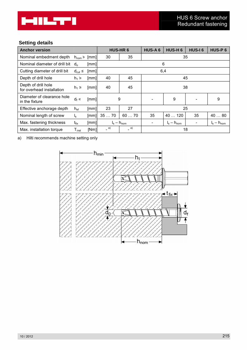
Setting detailsAnchor version HUS-HR 6 HUS-A 6 HUS-H 6 HUS-I 6 HUS-P 6
Nominal embedment depth hnom [mm] 30 35 35
Nominal diameter of drill bit do [mm] 6
Cutting diameter of drill bit dcut [mm] 6,4
Depth of drill hole h1 [mm] 40 45 45
Depth of drill holefor overhead installation
h1 [mm] 40 45 38
Diameter of clearance hole in the fixture
df [mm] 9 - 9 - 9
Effective anchorage depth hef [mm] 23 27 25
Nominal length of screw ls [mm] 35 … 70 60 … 70 35 40 … 120 35 40 … 80
Max. fastening thickness tfix [mm] ls – hnom - ls – hnom - ls – hnom
Max. installation torque Tinst [Nm] - a) - a) 18
a) Hilti recommends machine setting only
HUS 6 Screw anchorRedundant fastening
10 / 2012216
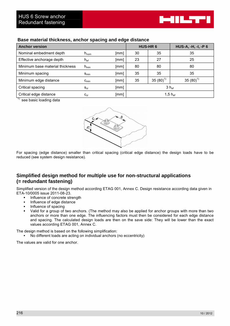
Base material thickness, anchor spacing and edge distanceAnchor version HUS-HR 6 HUS-A, -H, -I, -P 6
Nominal embedment depth hnom [mm] 30 35 35
Effective anchorage depth hef [mm] 23 27 25
Minimum base material thickness hmin [mm] 80 80 80
Minimum spacing smin [mm] 35 35 35
Minimum edge distance cmin [mm] 35 35 (80)1) 35 (80)1)
Critical spacing scr [mm] 3 hef
Critical edge distance ccr [mm] 1,5 hef1) see basic loading data
For spacing (edge distance) smaller than critical spacing (critical edge distance) the design loads have to be reduced (see system design resistance).
Simplified design method for multiple use for non-structural applications(= redundant fastening)Simplified version of the design method according ETAG 001, Annex C. Design resistance according data given in ETA-10/0005 issue 2011-08-23.
Influence of concrete strengthInfluence of edge distanceInfluence of spacingValid for a group of two anchors. (The method may also be applied for anchor groups with more than two anchors or more than one edge. The influencing factors must then be considered for each edge distance and spacing. The calculated design loads are then on the save side: They will be lower than the exact values according ETAG 001, Annex C.
The design method is based on the following simplification:No different loads are acting on individual anchors (no eccentricity)
The values are valid for one anchor.

HUS 6 Screw anchorRedundant fastening
10 / 2012 217
Design load – all load directions
Design resistance FRd = F0Rd fB f1 f2 f3 fre
Basic design resistance
Hilti����������
Data according ETA-10/0005, issue 2011-08-23
Anchor version HUS-HR 6 HUS-A, -H, -I, -P 6
Nominal embedment depth hnom [mm] 30 35 35
Basic design resistance in all load directions
35 c < 80 mm F0Rd [kN]
1,01,4 1,3
c 80 mm F0Rd [kN] 2,4 2,0
Influencing factors
Influence of concrete strengthConcrete strength designation(ENV 206) C 20/25 C 25/30 C 30/37 C 35/45 C 40/50 C 45/55 C 50/60
fB = (fck,cube/25N/mm²)0,5 a) 1 1,1 1,22 1,34 1,41 1,48 1,55
a) fck,cube = concrete compressive strength, measured on cubes with 150 mm side length
Influence of edge distance a)
c/ccr, 0,1 0,2 0,3 0,4 0,5 0,6 0,7 0,8 0,9 1
f1 = 0,7 + 0,3 c/ccr 0,73 0,76 0,79 0,82 0,85 0,88 0,91 0,94 0,97 1
f2 = 0,5 (1 + c/ccr 0,55 0,60 0,65 0,70 0,75 0,80 0,85 0,90 0,95 1
a) The edge distance shall not be smaller than the minimum edge distance cmin given in the table with the setting details. The influencing factors must be considered for every edge distance.
Influence of anchor spacing a)
s/scr 0,1 0,2 0,3 0,4 0,5 0,6 0,7 0,8 0,9 1
f3 = 0,5 (1 + s/scr 0,55 0,60 0,65 0,70 0,75 0,80 0,85 0,90 0,95 1
a) The anchor spacing shall not be smaller than the minimum anchor spacing smin given in the table with the setting details. This influencing factor must be considered for every anchor spacing.
Influence of reinforcementDense reinforcement Standard reinforcement a)
hnom [mm] 30 35 30 35
fre = 0,5 + hef 0,62 0,63 1
a) If in the area of anchorage there is reinforcement with a spacing mm (any diameter) or with a diameter
mm, then a factor fre,N = 1 may be applied.
HUS-A 6 / HUS-H 6 / HUS-I 6 / HUS-P 6 Screw anchor in precast prestressed hollow core slabs
10 / 2012218
HUS-A 6 / HUS-H 6 / HUS-I 6 / HUS-P 6 Screw anchorin precast prestressed hollow core slabs
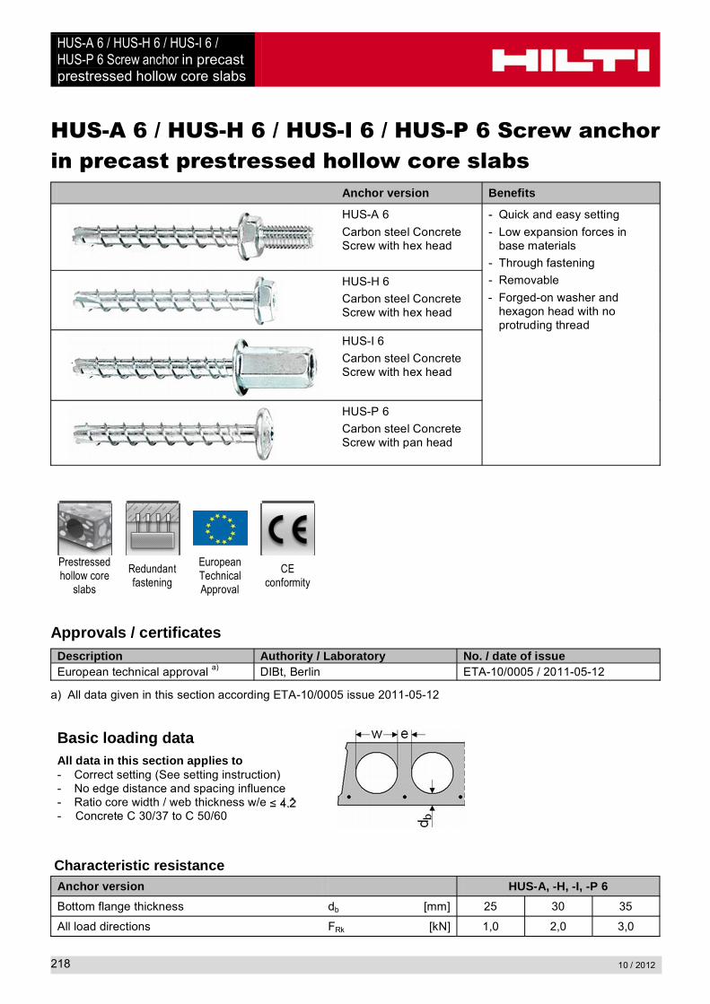
Anchor version Benefits
HUS-A 6
Carbon steel Concrete Screw with hex head
- Quick and easy setting
- Low expansion forces in base materials
- Through fastening
- Removable
- Forged-on washer and hexagon head with no protruding thread
HUS-H 6
Carbon steel Concrete Screw with hex head
HUS-I 6
Carbon steel Concrete Screw with hex head
HUS-P 6
Carbon steel Concrete Screw with pan head
Prestressed hollow core
slabs
Redundant fastening
European Technical Approval
CEconformity
Approvals / certificatesDescription Authority / Laboratory No. / date of issueEuropean technical approval a) DIBt, Berlin ETA-10/0005 / 2011-05-12
a) All data given in this section according ETA-10/0005 issue 2011-05-12
Basic loading dataAll data in this section applies to- Correct setting (See setting instruction)- No edge distance and spacing influence- Ratio core width / web thickness w/e - Concrete C 30/37 to C 50/60
Characteristic resistanceAnchor version HUS-A, -H, -I, -P 6
Bottom flange thickness db [mm] 25 30 35
All load directions FRk [kN] 1,0 2,0 3,0
HUS-A 6 / HUS-H 6 / HUS-I 6 / HUS-P 6 Screw anchor in precast prestressed hollow core slabs
10 / 2012 219
Design resistanceAnchor version HUS-A, -H, -I, -P 6
Bottom flange thickness db [mm] 25 30 35
All load directions FRd [kN] 0,7 1,3 2,0
Recommended loadsAnchor version HUS-A, -H, -I, -P 6
Bottom flange thickness db [mm] 25 30 35
All load directions a) Frec [kN] 0,5 1,0 1,4
a) With overall partial safety factor for action = 1,4. The partial safety factors for action depend on the type of loading and shall be taken from national regulations.
Requirements for redundant fasteningThe definition of redundant fastening according to Member States is given in the ETAG 001 Part six, Annex 1. In Absence of a definition by a Member State the following default values may be taken
Minimum numberof fixing points
Minimum numberof anchors per fixing point
Maximum design load of action NSd per fixing point a)
3 1 2 kN
4 1 3 kN
b) The value for maximum design load of actions per fastening point NSd is valid in general that means all fastening points are considered in the design of the redundant structural system. The value NSd may be increased if the failure of one (= most unfavourable) fixing point is taken into account in the design (serviceability and ultimate limit state) of the structural system e.g. suspended ceiling.
Materials
Mechanical propertiesAnchor version HUS-A, -H, -I, -P 6
Nominal tensile strength fuk [N/mm²] 930
Stressed cross-section As [mm²] 26,9
Moment of resistance W [mm³] 19,7
Design bending resistance MRd,s [Nm] 14,6
Material qualityAnchor version HUS-A, -H, -I, -P 6
MaterialCarbon steel,
galvanised to min. 5 µm

HUS-A 6 / HUS-H 6 / HUS-I 6 / HUS-P 6 Screw anchor in precast prestressed hollow core slabs
10 / 2012220
Anchor dimensions
Anchor version HUS-A 6 HUS-H 6 HUS-I 6 HUS-P 6
Nominal length lS [mm] 35 40..120 35 60..80
Outer diameter of thread dS [mm] 7,85
Core diameter dk [mm] 5,85
Head configuration
HUS-A 6 External threadM8 or M10
Square mark with d = 2 mm edge length for hnom = 35 mm
HUS-H 6 Hex head and Torx T30
HUS-I 6 Internal threadsM8 and M10
One circle mark with d = 0,8 mm for hnom = 35 mm
HUS-P 6 Pan head with
Setting
Anchor size HUS-A 6 HUS-I 6 HUS-H 6 HUS-P 6Rotary hammer Hilti TE 6 / TE 7
drill bit TE-CX 6
Socket wrench insertS-NSD 13 ½
LS-NSD 13 ½
(L)-
Torx - T30
Impact screw driver See setting instruction
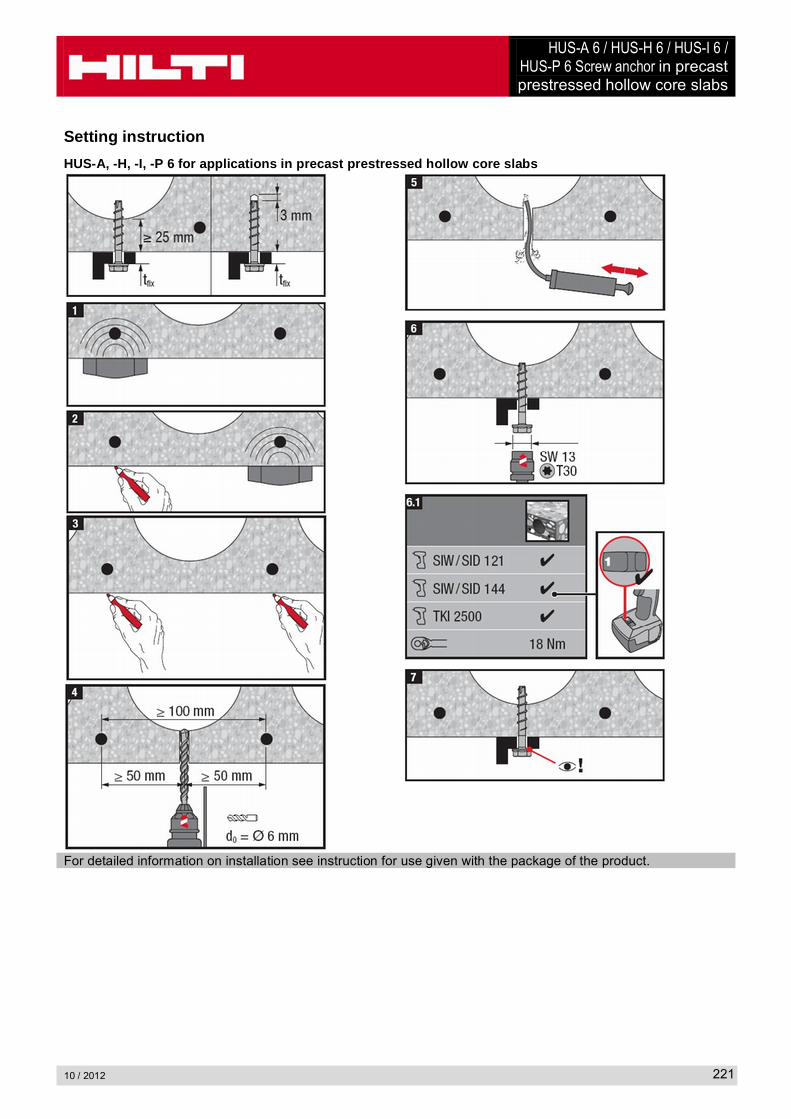
HUS-A 6 / HUS-H 6 / HUS-I 6 / HUS-P 6 Screw anchor in precast prestressed hollow core slabs
10 / 2012 221
Setting instruction
HUS-A, -H, -I, -P 6 for applications in precast prestressed hollow core slabs
For detailed information on installation see instruction for use given with the package of the product.
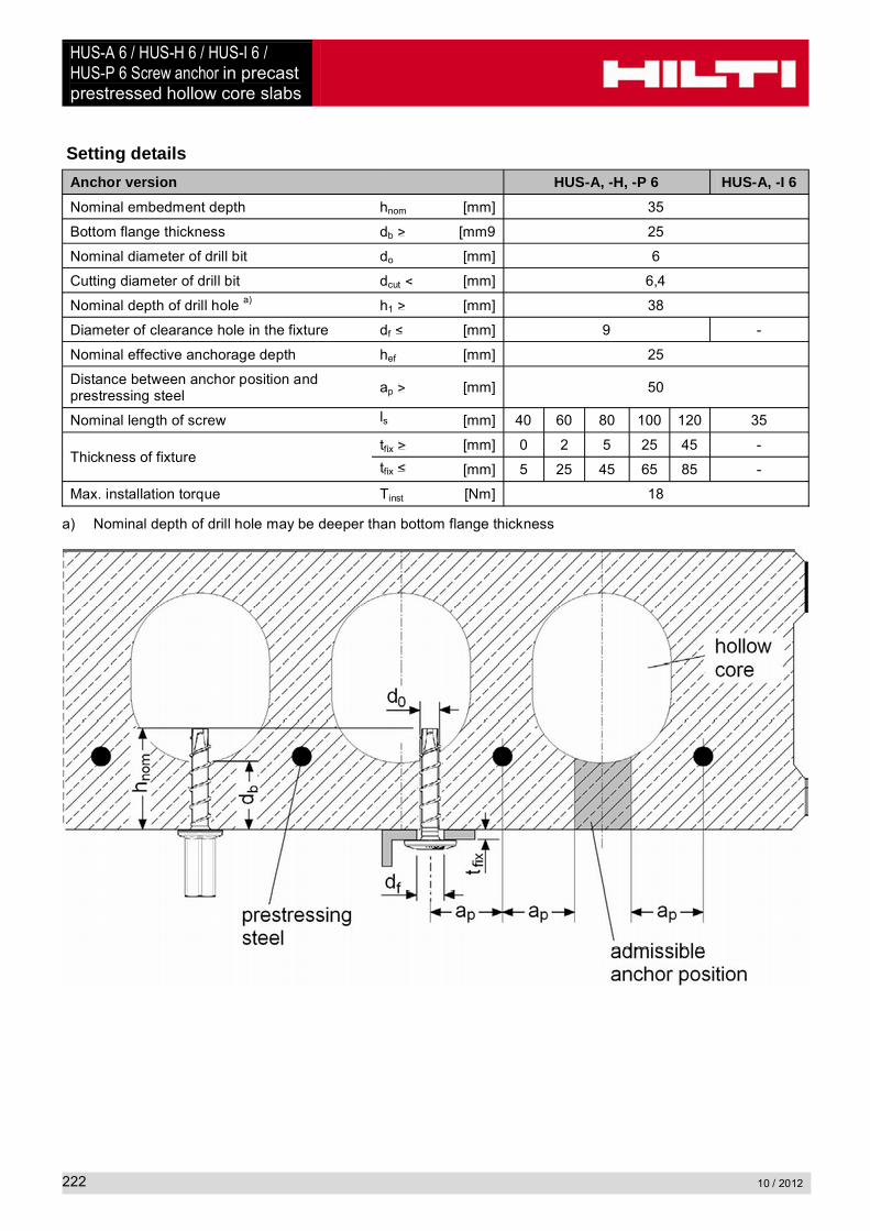
HUS-A 6 / HUS-H 6 / HUS-I 6 / HUS-P 6 Screw anchor in precast prestressed hollow core slabs
10 / 2012222
Setting details
Anchor version HUS-A, -H, -P 6 HUS-A, -I 6
Nominal embedment depth hnom [mm] 35
Bottom flange thickness db [mm9 25
Nominal diameter of drill bit do [mm] 6
Cutting diameter of drill bit dcut [mm] 6,4
Nominal depth of drill hole a) h1 [mm] 38
Diameter of clearance hole in the fixture df [mm] 9 -
Nominal effective anchorage depth hef [mm] 25
Distance between anchor position and prestressing steel
ap [mm] 50
Nominal length of screw ls [mm] 40 60 80 100 120 35
Thickness of fixturetfix [mm] 0 2 5 25 45 -
tfix [mm] 5 25 45 65 85 -
Max. installation torque Tinst [Nm] 18
a) Nominal depth of drill hole may be deeper than bottom flange thickness
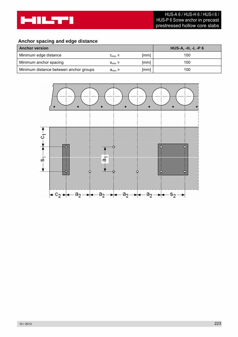
HUS-A 6 / HUS-H 6 / HUS-I 6 / HUS-P 6 Screw anchor in precast prestressed hollow core slabs
10 / 2012 223
Anchor spacing and edge distanceAnchor version HUS-A, -H, -I, -P 6
Minimum edge distance cmin [mm] 100
Minimum anchor spacing smin [mm] 100
Minimum distance between anchor groups amin [mm] 100

HUS 6 / HUS-S 6Screw anchor
10 / 2012224
HUS 6 / HUS-S 6 Screw anchorAnchor version Benefits
HUS 6
HUS-S 6
Carbon steel Concrete Screw
- Quick and easy setting
- Low expansion forces in base materials
- Through fastening
- Removable
ConcreteSmall edge
distance and spacing
Solid brick Hollow brickAutoclaved
aerated concrete
Redundant fastening
Fire resistance
Approvals / certificatesDescription Authority / Laboratory No. / date of issue
Fire test reportIBMB, BraunschweigDIBt, Berlin
UB 3574/5146 / 2006-05-20Z-21.1-1710 / 2009-05-20
Assessment report (fire) warringtonfire WF 166402 / 2007-10-26
Basic loading dataAll data in this section applies to- Correct setting (See setting instruction)- No edge distance and spacing influence- Concrete as specified in the table- Steel failure- Concrete C 20/25, fck,cube = 25 N/mm²
Note:When tightening the screw anchor in soft base materials and in hollow brick, care must be taken not to apply too much torque. If the screw anchor is over-tightened the fastening point is unusable for the HUS 6.
Solid masonry units:
o Mz 12 solid brick, compressive strength 12N/mm2, bulk density 1,8N/mm2, format mm (length/width/height)
o KS 12 solid lime block, compressive strength 12N/mm2, bulk density 2,0N/mm2, format 240/175/113 mm (length/width/height)The core/material ratio in bricks and solid sand lime blocks may not exceed 15% of a bed joint area.
Autoclaved aerated concrete:
o PB6 block, compressive strength 6 N/mm2, bulk density 0,6 N/mm2
o PB2 block, compressive strength 2 N/mm2, bulk density 0,2 N/mm2
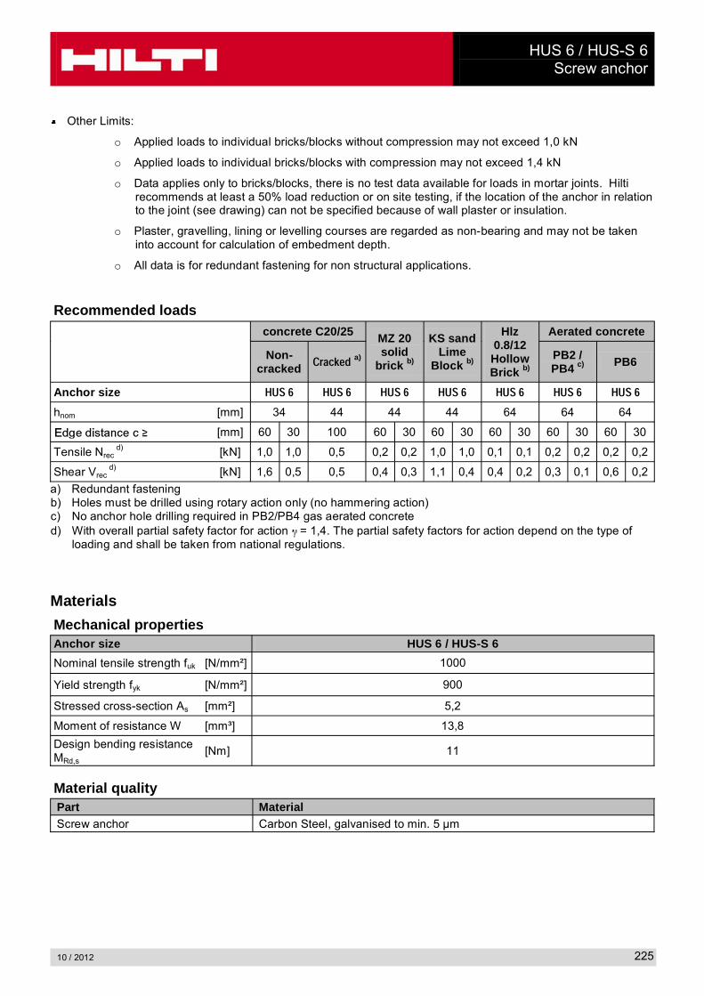
HUS 6 / HUS-S 6Screw anchor
10 / 2012 225
Other Limits:
o Applied loads to individual bricks/blocks without compression may not exceed 1,0 kN
o Applied loads to individual bricks/blocks with compression may not exceed 1,4 kN
o Data applies only to bricks/blocks, there is no test data available for loads in mortar joints. Hilti recommends at least a 50% load reduction or on site testing, if the location of the anchor in relation to the joint (see drawing) can not be specified because of wall plaster or insulation.
o Plaster, gravelling, lining or levelling courses are regarded as non-bearing and may not be taken into account for calculation of embedment depth.
o All data is for redundant fastening for non structural applications.
Recommended loads concrete C20/25 MZ 20
solid brick b)
KS sand Lime
Block b)
Hlz 0.8/12Hollow Brick b)
Aerated concrete
Non-cracked �������
a) PB2 / PB4 c) PB6
Anchor size ����� ����� ����� ����� ����� ����� �����
hnom [mm] 34 44 44 44 64 64 64
[mm] 60 30 100 60 30 60 30 60 30 60 30 60 30
Tensile Nrecd) [kN] 1,0 1,0 0,5 0,2 0,2 1,0 1,0 0,1 0,1 0,2 0,2 0,2 0,2
Shear Vrecd) [kN] 1,6 0,5 0,5 0,4 0,3 1,1 0,4 0,4 0,2 0,3 0,1 0,6 0,2
a) Redundant fasteningb) Holes must be drilled using rotary action only (no hammering action)c) No anchor hole drilling required in PB2/PB4 gas aerated concreted) With overall partial safety factor for action = 1,4. The partial safety factors for action depend on the type of
loading and shall be taken from national regulations.
Materials
Mechanical propertiesAnchor size HUS 6 / HUS-S 6
Nominal tensile strength fuk [N/mm²] 1000
Yield strength fyk [N/mm²] 900
Stressed cross-section As [mm²] 5,2
Moment of resistance W [mm³] 13,8
Design bending resistance MRd,s
[Nm] 11
Material qualityPart MaterialScrew anchor Carbon Steel, galvanised to min. 5 µm
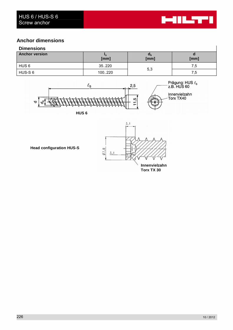
HUS 6 / HUS-S 6Screw anchor
10 / 2012226
Anchor dimensions
Dimensions Anchor version ls
[mm]dk
[mm]d
[mm]
HUS 6 35..2205,3
7,5
HUS-S 6 100..220 7,5
Head configuration HUS-S
HUS 6
InnenvielzahnTorx TX 30
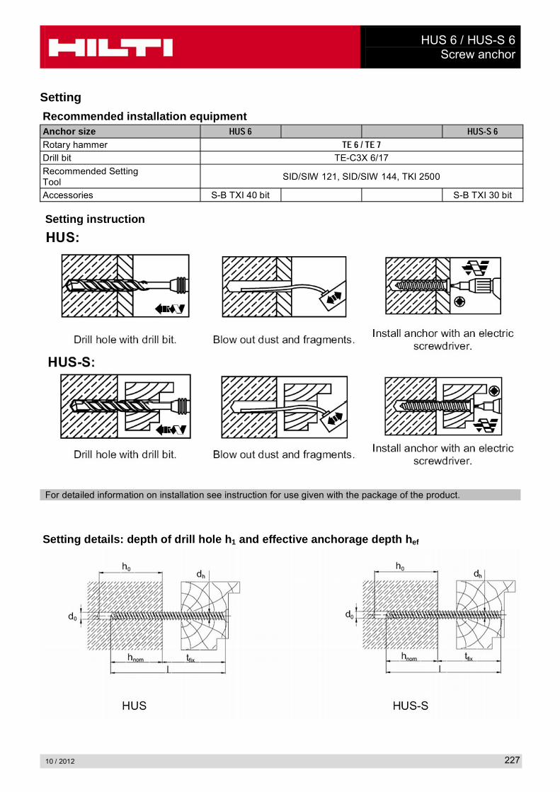
HUS 6 / HUS-S 6Screw anchor
10 / 2012 227
Setting
Recommended installation equipmentAnchor size ����� �������
Rotary hammer �����������
Drill bit TE-C3X 6/17
Recommended Setting Tool
SID/SIW 121, SID/SIW 144, TKI 2500
Accessories S-B TXI 40 bit S-B TXI 30 bit
Setting instruction
For detailed information on installation see instruction for use given with the package of the product.
Setting details: depth of drill hole h1 and effective anchorage depth hef

HUS 6 / HUS-S 6Screw anchor
10 / 2012228
Setting details
C20/25 Concrete
MZ 20 Brick/ KS 12 Block
Hollow Brick
Aerated Concrete
PB2/PB4 PB6
Nominal embedment depth hnom [mm] 34 44 64 64 64
Nominal diameter of drill bit do [mm] 6 6 6 - 6
Cutting diameter of drill bit dcut [mm] 6,4 6,4 6,4 - 6,4
Minimum depth of drill hole h1 [mm] 50 54 b) 64 a) - b) 70
Diameter of clearance hole in the fixture to clamp a fixture
df [mm]8,5
Diameter of clearance hole in the fixture for stand-off applications
df [mm]6,2
Max. fastening thickness tfix [mm] ls - hnom
Max. installation torque Tinst [Nm] 10 4 2 2 2
a) Holes must be drilled using rotary action only (no hammering action)b) No anchor hole drilling required in PB2/PB4 gas aerated concrete
Permissible anchor location in brick and block walls
Distance to free edge free edge to solid masonry (Mz and KS) units 200 mmDistance to free edge free edge to solid masonry (HLz and autoclaved aerated gas concrete) units 170 mmThe minimum distance to horizontal and vertical mortar joint (cmin) is stated in the recommended load table.Data applies only to bricks/blocks, there is no test data available for loads in mortar joints. Hilti recommends at least a 50% load reduction or on site testing, if the location of the anchor in relation to the joint (see drawing) can not be specified because of wall plaster or insulation.Minimum anchor spacing (smin) in one brick/block is cmin