and associates ebensburg pa f/6 number 3 (nos id- …
TRANSCRIPT

AD-A083 751 KIMBALL (L ROBERT) AND ASSOCIATES EBENSBURG PA F/6 13/13NATIONAL DAM INSPECTION PROGRAM. RAVEN RUN DAM NUMBER 3 (NOS ID--ETC(U)MAR AG R .J KIMBALL DACW31-6G C-6121
NCLASSIFIED
Nmmmhhmhmmhummiiiiimhmmi
IlK
I'1 11120
t '' IT 11.8
MICROCOPY RESOLUTION TEST CHANTNATIONAL BUREAU Of STANDARDS-1963- l
SUSQUEHANNA RIVER BASIN
LOST CREEK. SCHUYLKILL COUNTY
PENNSYLVANIA I0' RAVEN RUN DAM NO. 3
NOS 10 NO. PA-6OS
DER ID NO. 54-a
00 SHENANDOAH MUNICIPAL AUTHORITY0
9PHASE I INSPECTION REPORT
NATIONAL DAM INSPECTION PROGRAM
DTIC'.APR 2 4 1980.
11 C
premaed By
• .L. ROBERT KIMBALL & ASSOCIATES" 9 CONSULTING ENGINEERS & ARCHITECTS
EBENSBURG, PENNSYLVANIA
(-'. 'J" +159 %Is DcuRMT Is BZST QUALITY P AC TC IC .
"TIM COPY S ED TO DDC CONTAIN A
i Lt SIGNIFIC NT NUIBE OF PAGES WHIM DO MQ?
FORWPROIYUCY TFGIBLY.FOR
DEPARTMENT OF THE ARMY
* - BALTIMORE DISTRICT CORPS OF ENGINEERSBALTIMORE, MARYLAND
21203 This doclt
tor public reloCI ond til
ditr.bt1fliS uniflt

DISCLAIMER NOTICE
THIS DOCUMENT IS BEST QUALITYPRACTICABLE. THE COPY FURNISHEDTO DTIC CONTAINED A SIGNIFICANTNUMBER OF PAGES WHICH DO NOTREPRODUCE LEGIBLY.
/77
I
I

SUSOUEHANNA RIVER BASIN
LOST CREEK. SCHUYLKILL COUNTY
RAVEN.RUN.DAM .3NOS ID N. PA-656
DER ID N054-8)
Ll ?s u , ..-Lot Cr c, K,SSHENANOOAH0 M-tPA1 -THORITY
PHASE I INSPECTION REPORT*
L-OAMINSPECTION PROGRAM
... .
... L. RO, ERT KIMBALL & ASSOCIATESCONSULTING ENGINEERS & ARCHITECTS
EBENSBURG, PENNSYLVANIA
A~ W 153
FOR
DEPARTMENT OF THE ARMYBALTIMORE DISTRICT CORPS OF ENGINEERS
BALTIMORE, MARYLAND21203
. . .. . . & A" .O,;
.1, J .P 80
4

PREFACE
This report is prepared under guidance contained in theRecommended Guidelines for Safety Inspection of Dams, for PhaseI Investigations. Copies of these guidelines may be obtainedfrom the Office of Chief of Engineers, Washington, D.C. 20314.The purpose of a Phase I investigation is to identify expedi-tiously those dams which may pose hazards to human life or pro-perty. The assessment of the general condition of the dam isbased upon available data and visual inspections. Detailedinvestigation, and analyses involving topographic mapping, sub-surface investigations, testing, and detailed computational eva-luations are beyond the scope of a Phase I investigation;however, the investigation is intended to identify any need forsuch studies.
In reviewing this report, it should be realized that thereported condition of the dam is based on observations of field
conditions at the time of inspection along with data availableIto the inspection team. In cases where the reservoir waslowered or drained prior to inspection, such action, whileimproving the stability and safety of the dam, removes the nor-mal load on the structure and may obscure certain conditionswhich night otherwise be detectable if inspected under the nor-mal operating environment of the structure.
It is important to note that the condition of a dam depends on
numerous and constantly changing internal and external con -ditions, and is evolutionary in nature. It would be incorrectto assume that the present condition of the dam will continue torepresent the condition of the dam at some point in the future.Only through frequent inspections can unsafe conditions bedetected and only through continued care and maintenance can
* these conditions be prevented or corrected.
Phase I inspections are not intended to provide detailed hydro-logic and hydraulic analyses. In accordance with theestablished Guidelines, the spillway design flood is based onthe estimated "Probable Maximum Flood" for the region (greatestreasonably possible storm runoff), or fractions thereof. Thespillway design flood provides a measure of relative spillwaycapacity and serves as an aid in detemining the need for moredetailed hydrologic and hydraulic studies, considering the sizeof the dam, its general condition and the downstream damagepotential.
PHASE I REPORTNATIONAL DAM INSPECTION REPORT
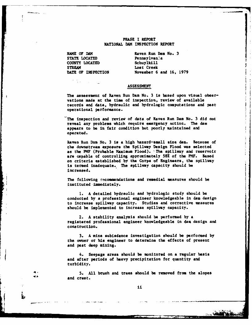
NAME OF DAM Raven Run Dam No. 3STATE LOCATED Pennsylvani:aCOUNTY LOCATED SchuylkillSTREAM Lost CreekDATE OF INSPECTION November 6 and 16, 1979
ASSESSMENT
The assessment of Raven Run Dam No. 3 is based upon visual obser-vations made at the time of inspection, review of availablerecords and data, hydraulic and hydrologic computations and pastoperational performance.
The inspection and review of data of Raven Run Dam No. 3 did notreveal any problems which require emergency action. The damappears to be in fair condition but poorly maintained andoperated.
Raven Run Dam No. 3 is a high hazard-small size dam. Because ofthe downstream exposure the Spillway Design Flood was selectedas the PMP (Probable Maximum Flood). 'The spillway and reservoirare capable of controlling approximately 58% of the PMF. Basedon criteria established by the Corps of Engineers, the 3piliwamyis termed inadequate., The spillway capacity should beincreased.
The following recommendations and remedial measures should beinstituted-immediately.
1. A detailed hydraulic and hydrologic study should beconducted by a professional engineer knowledgeable in dam designto increase spillway capacity. Studies and corrective measuresshould be implemented to increase spillway capacity.
2. A stability analysis should be performed by aregistered professional engineer knowledgeable in dam design andconstruction.
3. A mine subisdence investigation should be performed bythe owner or his engineer to determine the effects of presentand pest deep mining.
4. Seepage areas should be monitored on a regular basisand after periods of heavy precipitation for quantity andturbidity.
5. All brush and trees should be removed from the slopesand crest.
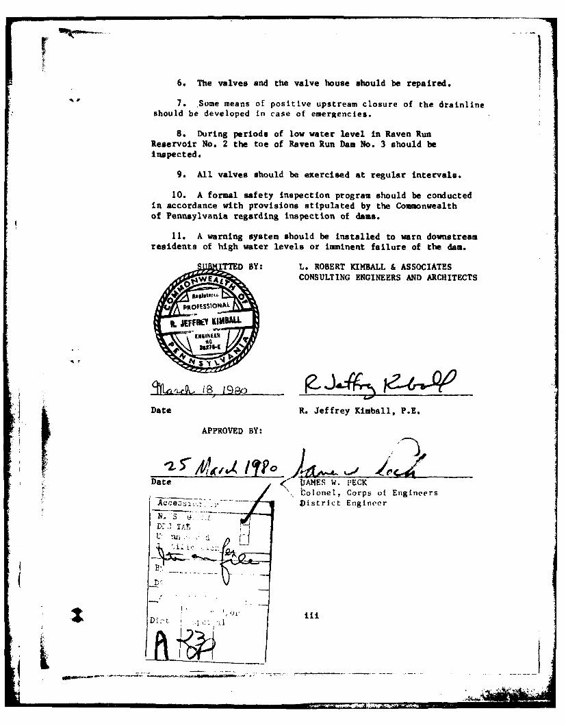
6. The valves and the valve house should be repaired.
7. Some means of positive upstream closure of the drainlineshould be developed in case of emergencies.
8. During periods of low water level in Raven RunReservoir No. 2 the toe of Raven Run Dam No. 3 should beinspected.
9. All valves should be exercised at regular intervals.
10. A formal safety inspection program should be conductedin accordance with provisions stipulated by the Commonwealthof Pennsylvania regarding inspection of dams.
11. A warning system should be Installed to warn downstreamresidents of high water levels or imminent failure of the dam.
ITTED BY: L. ROBERT KIMBALL & ASSOCIATESCONSULTING ENGINEERS AND ARCHITECTS
i ~IL ,W NYF~ KIMBL
k Date R. Jeffrey Kimball, P.E.
APPROVED BY:
Date D IAMES W. PECK. olonel, Corps of Engineers
z. , . ... District Engineer
4 n
Z D . . ........ . ... .
cu
0
04
'.4
iv0

TABLE OF CONTENTS
PAGE
SECTION 1 -PROJECT INFORMATION 1
1.1 General 11.2 Description of Project 11.3 Pertinent Data 3
SECTION 2 - ENGINEERING DATA 5
2.1 Design 52.2 Construction 52.3 Operation 52.4 Evaluation 5
SECTION 3 - VISUAL INSPECTION 6
3.1 Findings 63.2 Evaluation 7
SECTION 4 - OPERATIONAL PROCEDURES 8
4.1 Procedures 84.2 Maintenance of Dam 84.3 Maintenance of Operating Facilities 84.4 Warning System in Effect 8
SECTION 5 - HYDRAULICS AND HYDROLOGY 9
5.1 Evaluation of Features 95 5.2 Evaluation Assumptions 9
5.3 Summary of Overtopping analysis 105.4 Summary of Dam Breach Analysis 10I[SECTION 6 - STRUCTURAL STABILITY 11
6.1 Evaluation of Structural Stability 11
SECTION 7 - ASSESSMENT AND RECOMMENDATIONS/REMEDIALMEASURES 12
7.1 Dam Assessment 127.2 Recommendations/Remedial Measures 12
fVv
APPENDICES
APPENDIX A - CHECKLIST, VISUAL INSPECTION, PHASE IAPPENDIX B - CHECKLIST, ENGINEERING DATA, DESIGN, CONSTRUCTION,
OPERATION, PHASE IAPPENDIX C - PHOTOGRAPHSAPPENDIX D - HYDROLOGY AND HYDRAULICSAPPENDIX E - DRAWINGSAPPENDIX F - GEOLOGY
vi

PHASE INATIONAL DAM INSPECTION PROGRAM
RAVEN RUN DAM NO. 3NDI. I.D. NO. PA 656
DER I.D. NO. 54-8
SECTION 1PROJECT INFORMATION
1.1 General.
a. Authority. The National Dam Inspection Act, Public Law92-367, authorized the Secretary of the Army, through the Corpsof Engineers, to initiate a program of inspection of damsthroughout the United States.
b. Purpose. The purpose of the inspection is to determineif the dam constitutes a hazard to human life or property.
1.2 Description of Project.
a. Dam and Appurtenances. Raven Run Dam No. 3 is an earthand rockf ill dam 1,080 feet long and 40 feet high. The crestwidth of the dam varies from 10 feet wide to 24 feet wide. Theupstream slope above the water level is measured to be approxi-mately 3H:1V and the downstream slope is 1.5H:lV. The embank-ment consists of a center puddle core constructed of selectedimpervious material with both upstream and downstream rockf illzones with the exposed surfaces hand placed. The clay puddlecore was constructed from the original ground surface to theconglomerate rock for the entire length of the dam.
A secondary embankment (Right Arm) is located north of thetmain embankment. This embankment is 320 feet long and 7 feet
high. The crest width is 8 feet.- Both the upstream anddownstream slopes are 2H:1V. The upstream slope is protectedwith riprap. The embankment is constructed af a selectedmaterial with a puddle cutoff wall extending from the originalground surface into the conglomerate rock.
The spillway is located on the main embankment 780 feetfrom the left abutment. The spillway is rectangular shaped withstone masonry retaining walls forming the sides. The weirlength is 40 feet long. The spillway discharges into a gullycreated by erosion and eventually flows into Raven Run No. 2Reservoir. Beneath the spillway is a stone masonry cutoff wallin the puddle trench.
A 16" cast iron pipe passes beneath the damn at approximatelyoriginal ground surface. The pipe is supported on a dry laidvail extending down to the sandstone strata. In the reservoirthe pipe passes through a vertical masonry cutoff vail near theupstream toe of the embankment.* The entrance to the pipe isscreened vith a loosely laid dry masonry vail. No cutoffcollars are constructed along the pipe. Below the dam the pipepasses through a 10' x 16' masonry gate structure housing a 16"x 6" tee. The main 16" pipe serves as a blow off for drainingthe reservoir. Water is ordinarily discharged into the No. 2Reservoir through the 6" pipe.
b. Location. The dam is located on Lost Creek, two milesvest of Shenandoah, Schuylkill County, Pennsylvania. Raven RumDam No. 3 can be located on the Shenandoah, U.S.G.S. 7.5 minutequadrangle.
c. Size Classification. Raven Run Dam No. 3 is a smallsize structure (40 feet high, 278 acre-feet).
d. Hazard Classification. Raven Run Dam No. 3 is a highhazard dam. Downstream conditions indicate that loss of morethan a few lives is probable should the structure fail.* Onethousand feet downstream of the dam is Raven Rim Dam No. 2.Approximately 4,000 downstcream Lost Creek flows under a railroadembankment and through a culvert.* Ten dwellings are locatedimmediately downstream of this culvert.
e. Ownership. Raven Run Dam No. 3 is owned by theShenandoah Municipal Authority, Correspondence should beaddressed to:
Charles Dallazia, Manager* Shenandoah Municipal Authority
26 West Lloyd StreetShenandoah, PA 17976
- -I 717-462-1904
f. Purpose of Dam. Raven Run Dam No. 3 is used for watersupply
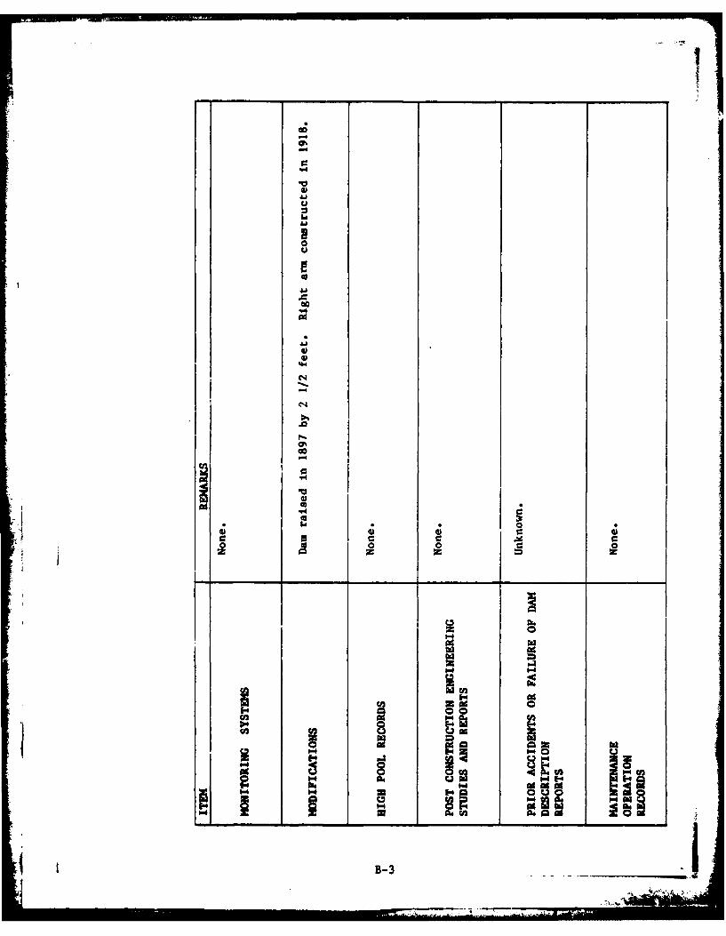
g. Design and Construction History. The dam was designedand construdtion was supervised by Heber S. Thompson, Engineerfor the Girard Water Company. The dam was constructed in 1884to 1885 by Thomas H. Rickert, a contractor located inPottsville, Pennsylvania. The dam was originally built toimpound the waters of Lost Creek, but the stream was first con-i taminated and finally destroyed by the mining operation of theLocust Mountain Coal Company. The Little Buck Mountain coalseam outcrops in the north arm of the reservoir and miningoperations reached close to the water surface.* A cave-in or cropfall occurred and water from the reservoir was lost to the mineat one point in time. In 1918 the right (north) arm embankmentwarn constructed.
2__ _ _

The height of the main embankment was increased by 2.5 feetin 1897.
h. Normal Operating Procedures. The north arm of thereservoir partially blocks flow into the reservoir. Water ispumped from the Ringtown reservoir into Raven Run No. 3 reser-voir through a cast iron pipe. A small amount of water is drawnoff the No. 3 reservoir to a small village. Excess water flowsinto Raven Run No. 2 Reservoir through the 6" water supply line.
1.3 Pertinent Data.
a. Drainage Area. 0.70 square miles
b. Discharge at Dam Site (cfs).
Maximum known flood at dam site UnknownSpillway capacity at top of dam 847Reservoir drain Unknown
c. Elevation (U.S.G.S. Datum) (feet). - Field survey basedon assumed pool elevation of 1610.0' as shown on U.S.G.S. 7.5minute quadrangle.
Top of dam - low point 1613.9Top of dam - OrIgia ul design height 1608.0Maximum pool - (PMF) 1614.6Normal pool 1610.3Emergency spillway crest 1610.3Streambed at centerline of dam Approximately 1574Maximum tailwater 1580.5
Toe of dam Approximately 1574
d. Reservoir (feet).
Length of maximum pool (PMF) 2000Length of normal pool 1100
e. Storage (acre-feet).
Normal pool 215Top of dam 278
f. Reservoir Surface (acres).
Top of dam 16.8Normal pool 14Spillway crest 14
3
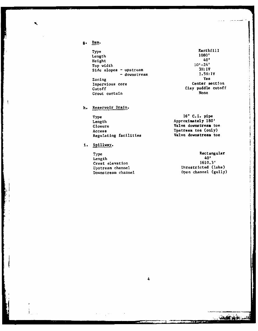
8. Dam
Type Earthfill
Length 1080'Height 40'
Top width 101-24'
Side slopes - upstream 3H:IV
- downstream 1.5H:1V
Zoning YesImpervious core Center sectionCutoff Clay puddle cutoffGrout curtain None
h. Reservoir Drain.
Type 16" C.I. pipe
Length Approximately 180'Closure Valve downstream toe
Access Upstream toe (only)Regulating facilities Valve downstream toe
i. Spillway.
Type RectangularLength 40'Crest elevation 1610.3'Upstream channel Unrestricted (lake)
Downstream channel Open channel (gully)
4
SECTION 2ENGINEERING DATA
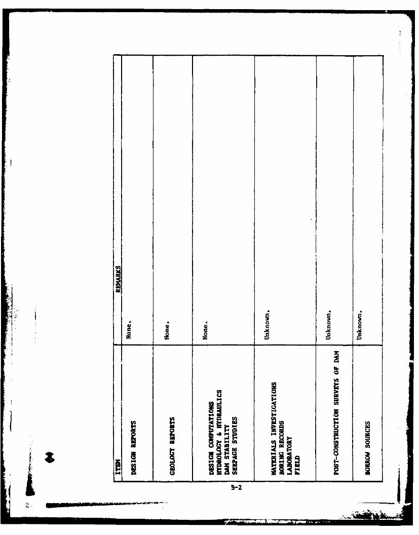
2.1 Design. Review of information in the files of theCommonwealth of Pennsylvania, Department of EnvironmentalResources revealed that several construction drawings wereavailable for review. In addition, design summary reports,inspection reports, permit, photographs and correspondence wereavailable for review. These data were reviewed for this study.
2.2 Construction. No information other than constructiondrawings were av-ailable on the original dam. C.;ns tructiondrawings and site visit reports are available on the construc-tion of the North Arm. No other data were available on theconstruction.
2.3 Operation. No operating records are maintained.
2.4 Evaluation.
a. Availability. Engineering data were provided byPennDER, Bureau of Dams and Waterway Management. No engineeringdata were provided by the owner. A representative of the owneraccompanied the inspection team to answer questions on operationand maintenance of the dam. The owner did not provide anyinformation on past deep mining activities in the area of thedam and reservoir.
* b. Adequacy. The type and amount of design data and otherengineering information are sketchy. The Phase I Report is pre-
:1 pared based on observed conditions, review of the available dataand hydrologic and hydraulic analysis.
SECTION 3
VISUAL INSPECTION
3.1 Findings.
a. General. The onsite inspection of Raven Run Dam No. 3was conducted by personnel of L. Robert Kimball and Associatesaccompanied by a representative of the Shenandoah MunicipalAuthority on November 16, 1979. The inspection consisted of:
1. Visual inspection of the retaining structure,abutments and toe.
2. Examination of the spillway facilities, exposedportion of any outlet works and other appurtenantstructures.
3. Observations affecting the runoff potential ofthe drainage basin.
4. Evaluation of the downstream area hazard potential.
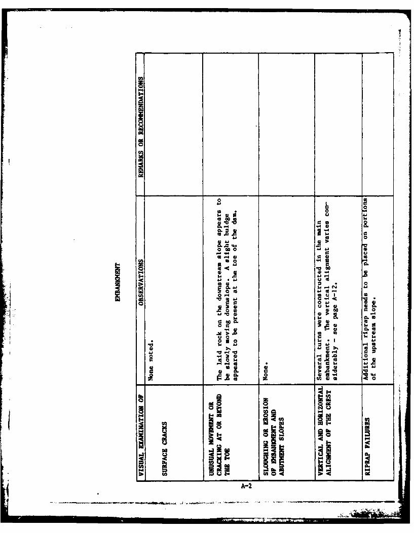
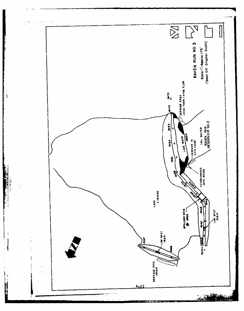
b. Dam. The dam appears to be in fair condition. From abrief survey conducted during the inspection, it was noted thatthe elevation of the crest of the dam varies considerably (seepage A-12). The upstream slope of the main embankment above thewater level is measured to be 3H:LV. However, the constructiondrawings show the downstream slope to be 2H:1V. The downstreamslope was measured to be 1.5H:LV. The crest width varied from10 feet to 24 feet wide. A power line crosses the main embank-ment crest. Trees and brush are growing on both the upstreamand downstream slopes and the crest. Some riprap, is missingfrom the upstream slope. The laid rock on the downstream slopenear the maximum section of the main embankment show some signsof movement. The toe shows some signs of bulging. Tailwater ispresent from the Raven Run No. 2 Reservoir and made examinationof the toe below this tailwater impossible. Along the leftabutment near the toe of the dam a seepage area was present. Atthe time of inspection less than 1 gallon per minute of flow wasmeasured.
The right arm embankment has a crest width of 8 feet and theupstream and downstream slopes are 2H:1V. Considerable growthof trees and small brush is present on both slopes and thecrest. Standing water was present along the toe of the embank-ment.* This water appears to be trapped against the toe.
c. 'Appurtenant Structures. The water level at the time ofinspection was just below the spillway crest (elevation 1610.0).The spillway appeared to be in good condition. Several of themasonry stones forming the sidewalls of the spillway need to berepaired.
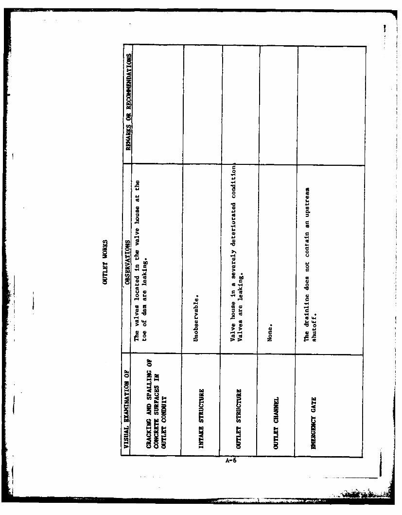
The valve house at the toe of the main embankment is in avery deteriorated condition. The valves in the valve house areleaking and the condition of the valves is questionable. Thereservoir drain contains no upstream shutoff.
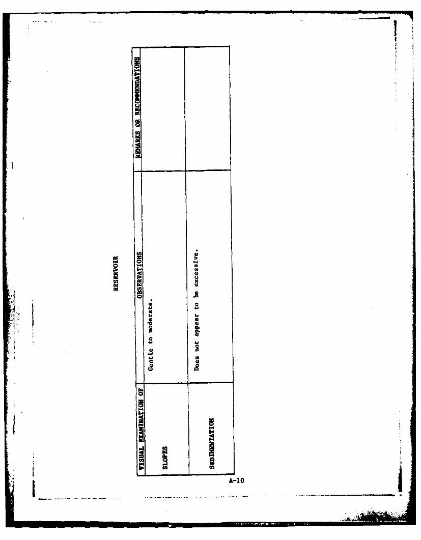
d. Reservoir Area. The watershed is covered partiallyvith timber land and strip inines. The reservoir slopes aregentle to moderate and are not susceptible to massive landslideswhich would effect the storage volume of the reservoir or over-topping of the dam by displacing water.
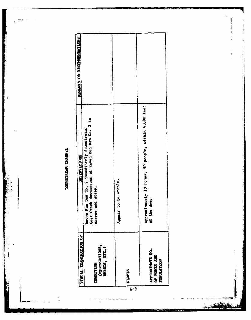
e. Downstream Channel. Immediately downstream of RavenRun Dam No. 3 is Raven Run Dam No. 2. Downstream of Raven RunDam No. 2 Lost Creek is narrow and steep. Approximately 10dwellings are located 4,000 feet downstream of Raven Run Dam No.3.
3.2 Evaluation. In general, the embankment appeared to be infair condition and the appurtenant structures in poor condition.The seepage area and apparent slow movement of the rock on thedownstream slope are of concern and should be monitored at regu--lar intervals. The spillway and reservoir drain should berepaired and maintained. An upstream shutoff should be providedon the draloline.
7

SECTION 4OPERATIONALL PROCEDURES
4.1 Procedures. Water is pumped from the Ringtown ReservoirInto Raven Ruin Dam No. 3. 4 minor amount of water is drawn offthe reservoir to a small village. The reservoir is maintainedat the spillway crest. Water is drawn off the reservoir throughthe 16" and 6" lines into Raven Run Reservoir No. 2. Excesswater is discharged through the spillway.
4.2 Maintenance of the Dam. No planned maintenance scheduleexists. Maintenance o[ the dam is performed by the MunicipalAuthority staff. Maintenance of the dam is considered poor.
4.3 Maintenance of Operating Facilities. Maintenance of thevalve house and valves has been severely lacking. No main-tenance schedule exists. Maintenance of the operating facili-ties is considered poor.
4.4 Warning System in Effect. All reservoirs in the ShenandoahMunicipal Authorities system are checked daily. However, thereis no official system to warn downstream residents of largespillway discharges or imminent failure of the darm.
4.5 Evaluation. Maintenance of the dam and operating facilitesis considered poor. There is no warning system in effect towarn downstream residents.
SECTION 5HYDRAULICS AND HYDROLOGY
5.1 Evaluation of Features.
a. Design Data. No calculations or design data pertainingto hydrology were available.
b. Experience Data. No rainf all, runoff or reservoirlevel data were available. The spillway reportedly has func-tioned adequately in the past.
c. Visual Observations. The spillway appeared to be infair condition but poorly maintained.
A low spot was noted on the dam embankment between theright abutment and the spillway wingwall. This area couldeasily be filled to the top of dam elevation.
d. Overtopping Potential. Overtopping potential wasinvestigated through the development of the probable maximumflood (PI4F) for the watershed and the subsequent routing of thePMF and fractions of the PMP through the reservoir and spillway.
The Corps of Engineers, Baltimore District, has directedthat the HEC-i Dam Safety Version systemized computer program beutilized. The program was prepared by the HydrologicEngineering Center (NEC), U.S. Army Corps of Engineers, Davis,California, July, 1978. The major methodologies or key inputdata for this program are discussed briefly in Appendix D.
5.2 Evaluation Assumptions. To enable us to complete thehydraulic and hydrologic analysis for this structure, it wasnecessary to make the following assumptions.
1.* The potential for runoff losses into mine openings wasnot considered.
2. The right arm of the embankment, which was constructedin 1917 to reduce storage losses into a mine cave, was not con-sidered In our analyses. Its effects on inflow and storagewould require a detailed Investigation beyond the scope of thisreport.
"rw

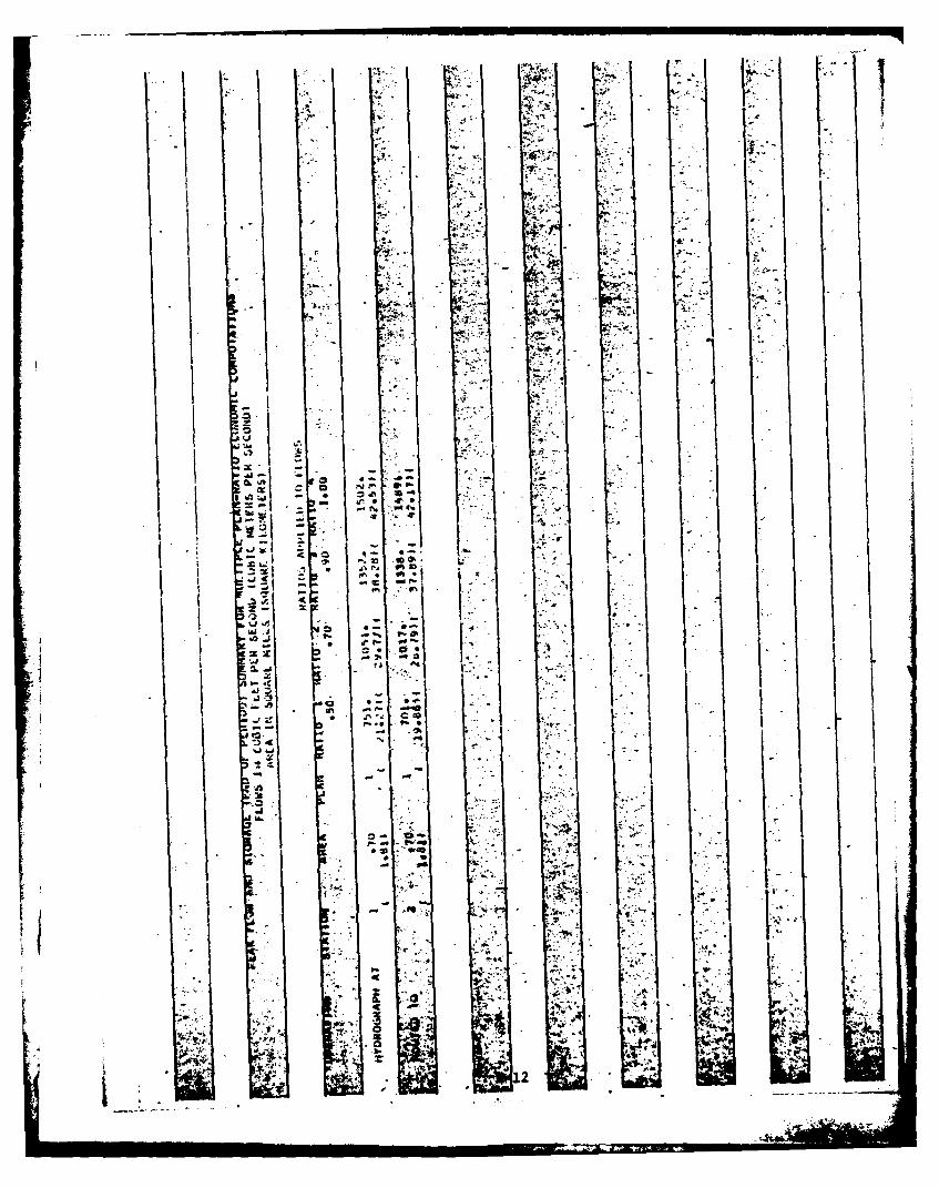
5.3 Summary of Overtopping Analysis. Complete summary sheetsfor the computer output are presented in Appendix D.
Peak inflow (PMF) 1502 cfsSpillway capacity 847 cfs
a. Spillway Adequacy Rating. The Spillway Design Flood(SDF) for this dam is the FMF. The SDF is based on the hazardand size classification of the dam. Based on the followingdefinition provided by the Corps of Engineers, the spillway israted as inadequate as a result of our hydrologic analysis.
Inadequate - For all high hazard dams which do not safelypass the SD! (PMF).
The spillway and reservoir are capable of controllingapproximately 58Z of the PMF without overtopping the embankmentat elevation 1613.9 (low spot). A computer printout of the hydro-logy is included in Appendix D.
5.4 Summary of Dam Breach Analysis. As the subject dam cansatisfactorily pass 50Z of the PMF without failure (based on ouranalysis) it was not necessary to perform a breach analysis anddowns:ream routing of the flood wave.
4 10
- *

SECTION 6STRUCTURAL STABILITY
6.1 Evaluation of Structural Stability.
a. Visual Observations. The rockfill on the downstreamslope of the main embankment showed some evidence of minor move-ment. The downstream slope of the dam is very steep (1.5H:IV).
In addition, a bulge appeared to be present near the toe of thedam. Some slow movement of the downstream slope was in evidencefrom the bending of trees. The downstream below the tailwatercould not be examined because of the tailwater condition.
Seepage was present on the right abutment near the toe of dam.
This seepage was measured to be less than 1 gallon per minute.
b. Design and Construction Data. No stability analyseswere conducted for the design of this dam. No other design orconstruction data are available on the structural stability of
the dam.
c. Operating Records. No operating records are maintained.
d. Post Construction Changes. In 1897 the main embankmentwas raised 2 1/2 feet. No information is available on this modi-fication. In 1918 the north arm embankment was constructed toeliminate loss of water into mine workings.
e. Seismic Stability. The dam is located in seismic zone1. No seismic stability analyses has been performed. Normally,
it can be considered that if a dam in this zone is stable understatic loading conditions, it can be assumed safe for anyexpected earthquake loading.
11
I l ..: Fz = ...
SECTION 7
ASSESSMENT AND RECOMNENDATIONS/REKEDIAL N.ASURES
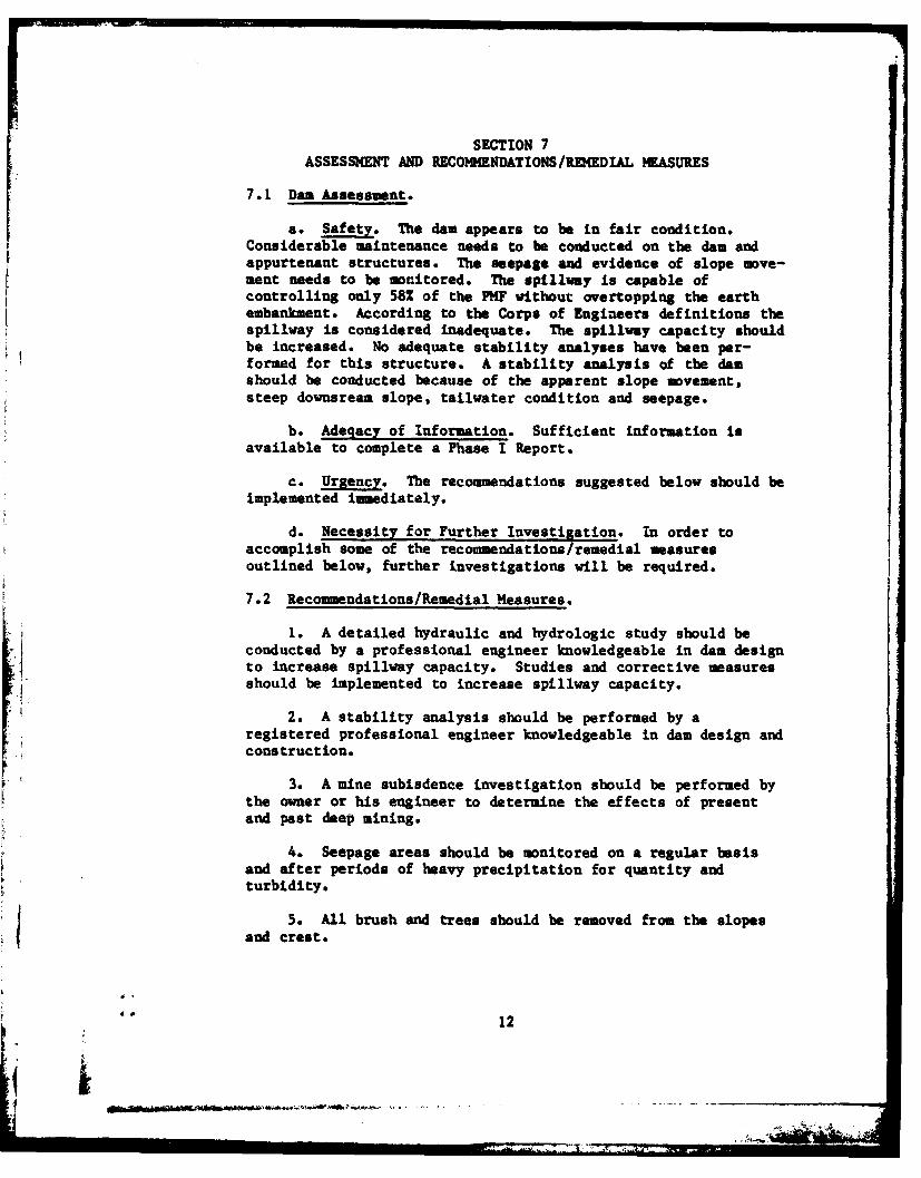
7.1 Dan Assessment.
a. Safety. The dam appears to be in fair condition.Considerable maintenance needs to be conducted on the dam andappurtenant structures. The seepage and evidence of slope move-ment needs to be monitored. The spillway is capable ofcontrolling only 58% of the PNF without overtopping the earthembankment. According to the Corps of Engineers definitions thespillway is considered inadequate. The spillway capacity shouldbe increased. No adequate stability analyses have been per-formed for this structure. A stability analysis of the damshould be conducted because of the apparent slope movement,steep downsream slope, tailwater condition and seepage.
b. Adeqacy of Information. Sufficient information isavailable to complete a Phase I Report.
c. Urgency. The recommendations suggested below should beimplemented immediately.
d. Necessity for Further Investigation. In order toaccomplish some of the recommendations/remedial measuresoutlined below, further investigations will be required.
7.2 Recommendations/Remedial Measures.
1. A detailed hydraulic and hydrologic study should beconducted by a professional engineer knowledgeable in dam designto increase spillway capacity. Studies and corrective measuresshould be implemented to increase spillway capacity.
2. A stability analysis should be performed by aregistered professional engineer knowledgeable in dam design andconstruction.
3. A mine subisdence investigation should be performed bythe owner or his engineer to determine the effects of presentand past deep mining.
4. Seepage areas should be monitored on a regular basisand after periods of heavy precipitation for quantity andturbidity.
5. All brush and trees should be removed from the slopesand crest.
F 12
b-.I. a.>

6. The valves and the valve house should be repaired.
7. Some means of positive closure on the upstream end of thedrainline should be developed in case of emergencies.
8. During periods of low water level in Raven Run
Reservoir No. 2 the toe of Raven Run Dam No. 3 should be
9. All valves should be exercised at regular Intervals.
10. A formal safety inspection program should be conductedin .accordancane with provisions stipulated by the Commonwealthof Pennsylvania regarding inspection of dams.
11. A warning system should be installed to warn downstreamresidents of high water levels or imminent failure of the dam.
13

APPENDIX ACHECKCLIST, VISUAL INSPECTION, PHASE I

12
oJl-4
4pa
N i
pa'
00
E- t h
44 U3 -0C3
Ai h
'-4"4 A r
AjA
04.
OhP4 co4
-944
4)
C.) 4 4
=4 U 3hi~3 P.4
W4I
41 O 0
0 .ba 00
44
S"4l 0 ti
to 0CL4 Aj C18 4.. co .
Ka* 00- ut
0 c 4
0 a-0A1 r 0.
A 0
U) ~ 00.
pqIi~. 4.4
U) U)~ .p40 ~4I0. 0 U)504 I.
2 2 UU)Sad
hiA-2

to______ _______ o_______
0
* a z
a 0ed4)0) j
4) (a
0 0) w .
0) c
0)00
0 A00
I~Id
0 0
C.CA
A-3
:ZA 7770 700
E-Idhii
w4" HC
I- -
41 A
U)A
zA-4
WI=0
i.ca
.... _ _ __ _ __ _ __ _ _ _ __ __ _
= 0o H
.0.0.0. .0 ,
"2 " - -4W
1.4 a
W P3
CA 3
A-5
0
a
*) 0 w
o
II'.V-4
10 aBP~ W
It;
A-6

'-P4
14
a. 0
4 PU
14 00
60% 60
-A
*1..4
04 .40
ci I
ft-A 7 0
10
.4L64
- 8-
caa
0 4) co
4))414
P, 0
*14
040
pbp
A-
U,
I
$
I II _______ ________
a'-- 0 q.4I- UU
4 QJU- xU)
o * Ca..UU)U
0 'a0
hi0
.1
.4II
& I_____________________
C
61 ~ A- 6161
0
09
I.
I=
0 I
wN
0a
CC2d
AZ..
0 W
A~.2c

00Nz
K 4?
-. j
- Ij
Oco
A-1 3
APPENDIX B
CHECKLIST, ENGINEERING DATA, DESIGN, CONSTRUCTION, OPERATION,
PHASE I
t I
ij'

1-4
i
"40
1-44
E-4 b]
0 in
o 'to00 t
la d -4 A$W - f
cc 4 -4 -4 r
w 0g~ ,z
-4-
B-10
04 o 1
3-2
IdI-44
40)
4.'4
ac
-B-
4i.i

'4B-4
U'w--6
A ENtPHOTOGRAPHS
z qz
C.)
zz
0 IILz 2
Iaz
og
MENE

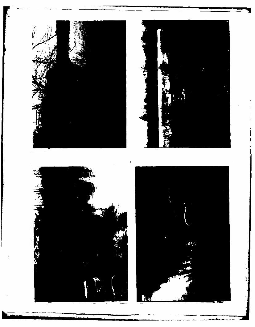
RAVEN RUN DAm No. 3
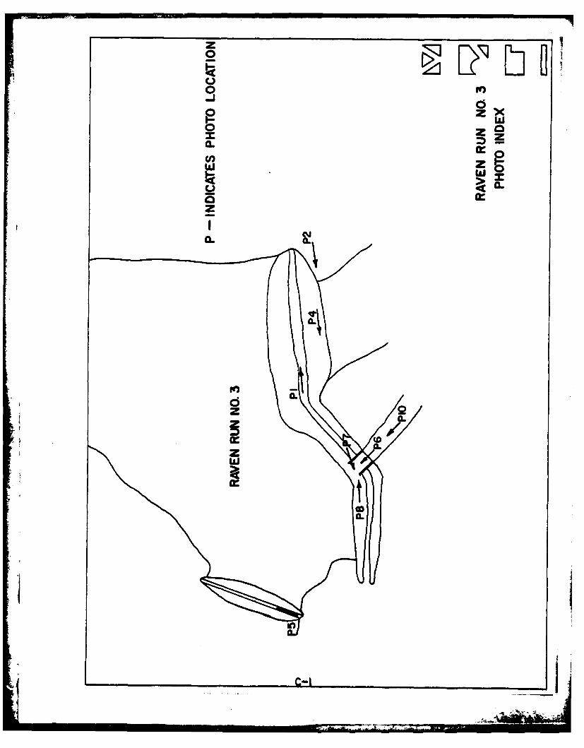
Photograph Descriptions
Sheet 1. Front
(1) Upper left - Crest of main embankment.
(2) Upper right - Downstream slope view from left abutment.
(3) Lower left - View of Raen Run Dam No. 2 and Raven Run
Dam No. 3.
(4) Lower right - Downstream slope at maximum section.
Note deteriorated valve house at toe.
Sheet 1. Back
(5) Upper left - Upstream slope and crest of right arm
embankment.
(6) Upper right - Spillway.(7) Lower left - Upstream slope of dam to the right of the
spillway.
(8) Lower right - Spillway weir.
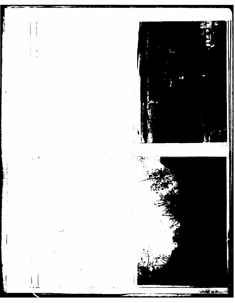
Sheet 2. Front
(9) Upper right - Downstream exposure below Raven Run DamNo. 2. Dams in upper right corner.
(10) Lower right - Vegetation in spillway discharge channel
looking towards weir.
c-2
__________________________ ___________IA
'S
i~~7:z7J..
a
~
'I7~*. -
44
&
D~, *'*
4~.
.p. *,i~'~
-

APPENDIX DHYDROLOGY AND HYDRAULICS
I
APPENDIX D
HYDROLOGY AND HYDRAULICS
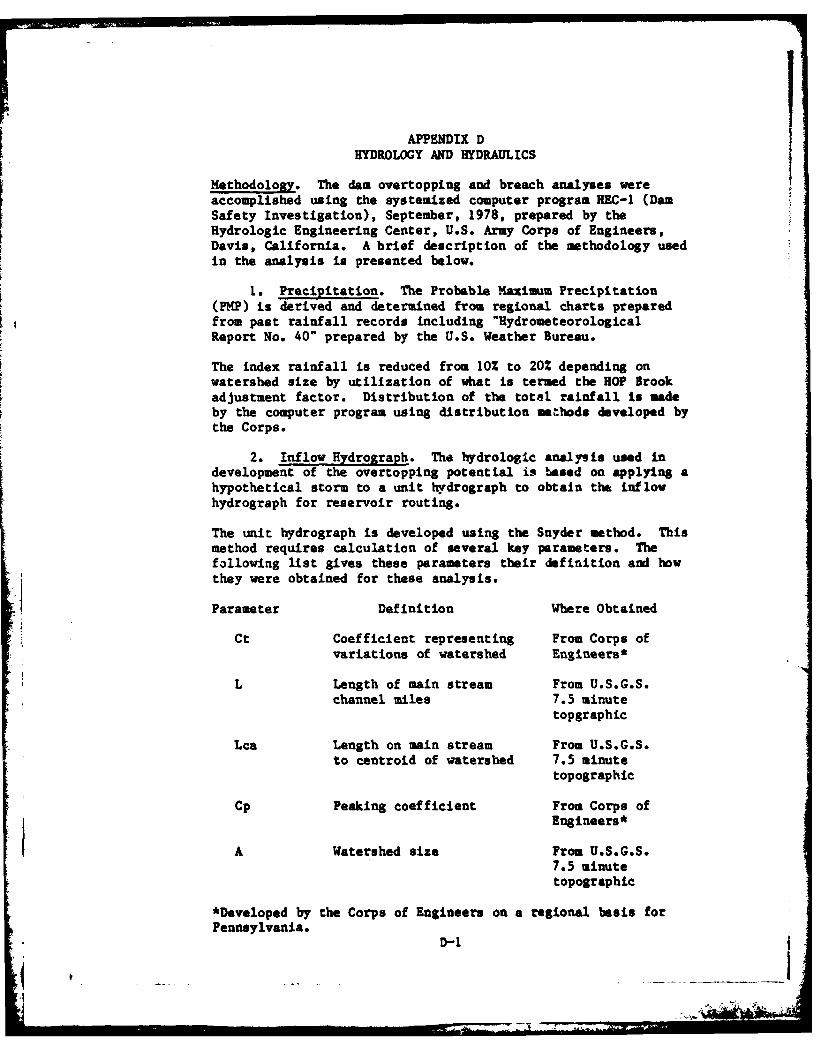
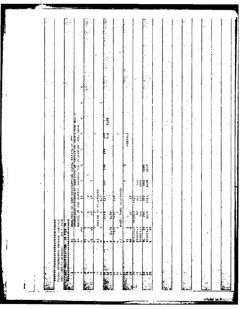
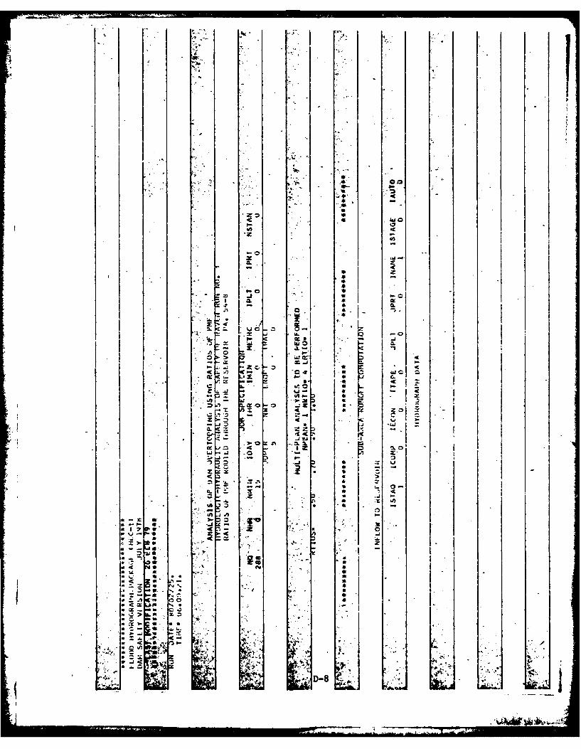
Methodology. The dam overtopping and breach analyses wereaccomplished using the systemized computer program HEC-1 (DamSafety Investigation), September, 1978, prepared by theHydrologic Engineering Center, U.S. Army Corps of Engineers,Davis, California. A brief description of the methodology usedin the analysis is presented below.
1. Precipitation. The Probable Maximum Precipitation(PMP) is derived and determined from regional charts preparedfrom past rainfall records including "HydrometeorologicalReport No. 40" prepared by the U.S. Weather Bureau.
The index rainfall is reduced from 10% to 20% depending onwatershed size by utilization of what is termed the HOP Brookadjustment factor. Distribution of the total rainfall is madeby the computer program using distribution methods developed bythe Corps.
2. Inflow Hydrograph. The hydrologic analysis used indevelopment of the overtopping potential is based on applying ahypothetical storm to a unit hydrograph to obtain the inflowhydrograph for reservoir routing.
The unit hydrograph is developed using the Snyder method. Thismethod requires calculation of several key parameters. Thefollowing list gives these parameters their definition and howthey were obtained for these analysis.
Parameter Definition Where Obtained
Ct Coefficient representing From Corps ofvariations of watershed Engineers*
L Length of main stream From U.S.G.S.channel miles 7.5 minute
topgraphic
Lca Length on main stream From U.S.G.S.to centroid of watershed 7.5 minute
topographic
Cp Peaking coefficient From Corps ofEngineers*
A Watershed size From U.S.G.S.7.5 minutetopographic
*Developed by the Corps of Engineers on a regional basis forPennsylvania.
D-1I_
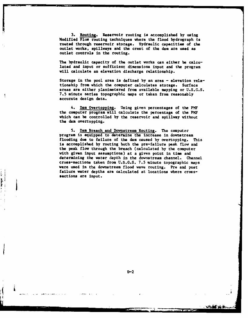
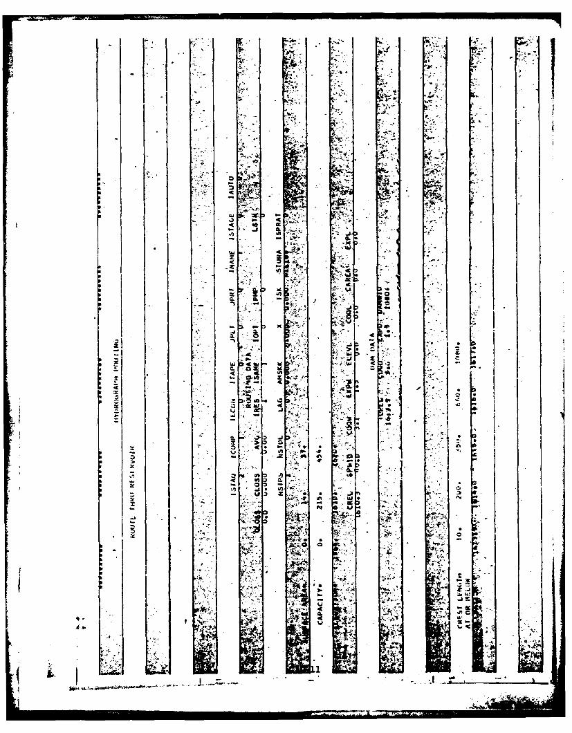
3. Routing. Reservoir routing is accomplished by usingModified Plus routing techniques where the flood hydrograph isrouted through reservoir storage. Hydraulic capacities of theoutlet works, spillways and the crest of the dam are used asoutlet controls in the routing.
The hydraulic capacity of the outlet works can either be calcu-lated and input or sufficient dimensions input and the programwill calculate an elevation discharge relationship.
Storage in the pool area is defined by an area - elevation rela-tionship from which the computer calculates storage. Surfaceareas are either planimetered from available mapping or U.S.G.S.7.*5 minute series topographic maps or taken from reasonablyaccurate design data.
4. Dam Overtopping. Using given percentages of the P4Fthe computer program will calculate the percentage of the PMFwhich can be controlled by the reservoir and spillway withoutthe dam overtopping.
5. Dam Breach and Dowstrea Routing. The computerprogram is equipped to determine the increase in downstreamflooding due to failure of the dam caused by overtopping. Thisis accomplished by routing both the pre-failure peak flow andthe peak flow through the breach (calculated by the computerwith given input assumptions) at a given point in time anddetermining the water depth in the downstream channel. Channelcross-sections taken from U.S.G.S. 7.5 minute topographic mapswere used in the downstream flood wave routing. Pre and postfailure water depths are calculated at locations where cross-
sections are input.
D-2
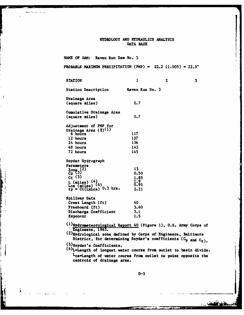
HYDROLOGY AND HYDRAULICS ANALYSISDATA BASE
NAME OF DAM: Raven Run Dam No. 3
PROBABLE MAXIMUM PRECIPITATION (PMP) - 22.2 (1.005) - 22.3"
STATION 1 2 3
Station Description Raven Run No. 3
Drainage Area(square miles) 0.7
Cumulative Drainage Area(square miles) 0.7
Adjustment of PMF forDrainage Area (Z)(1)6 hours 117
12 hours 12724 hours 13648 hours 14372 hours 145
Snyder HydrographParametersZon (2) 13Cpt3) 0.50Ct (3) 1.85L (miles) (4 1.9Lea (miles) J 0.95tp = Ct(LxLca) 0.3 hrs. 2.21
Spillway DataCrest Length (ft) 40Freeboard (ft) 3.60Discharge Coefficient 3.1Exponernt 1.5
(1 )!Zdrometeorological Report 40 (Figure 1), U.S. Army Corps ofEngineers, 1965.
(2)Hydrological zone defined by Corps of Engineers, BaltimoreDistrict, for determining Snyder's coefficients (Cp and Ct).
(3)Snyder' s Coefficients.(4)L-Length of longest water course from outlet to basin divide.
Lca-Length of water course from outlet to point opposite thecentroid of drainage area.
&D-3

ICHECK LIST
HYDROLOGIC AND HYDRAULICENGINEERING DATA
DRAINAGE AREA CHARACTERISTICS: D.A.-O.7 mi2 Wooded. Large Strip Area
ELEVATION TOP NORMAL POOL (STORAGE CAPACITY): 215 Ac.ft.
ELEVATION TOP FLOOD CONTROL POOL (STORAGE CAPACITY): 278 ac.ft.
ELEVATION MAXIMUM DESIGN POOL: Unknown
ELEVATION TOP DAM: 1613.9 feet
SPILLWAY CREST:
a. Elevation 1610.3 feet
b. Typo Rectangularc. Width 40 feetd. Length Unl:no~ne. Location Spillover Right abutmentf. Number and Type of Gates None
OUTLET WORKS:
a. Type 16" CIP
b. Location Tn,,eh .nv4. .. 4,1nc. Entrance inverts UnknoWn
d. Exit inverts Unknowne. Emergency draindown facilities CIP
HYDROMETEOROLOGICAL GAUGES:
a. Type Noneb. Locationc. Records ____
MAXIMUM NON-DAMAGING DISCHARGE: Unknown
D-4
IH
DANMNAME E~vilN 3uJ~oL ROBERT KIMBALL & ASSOCIATES 'D' NUMER
0' CONSULTING ENGINEERS A ARCHITECTS $MEET NO.-OF S
M ESENSURG PENNSYLVANIA BY0 ' M~Z DATE I- z5s-so
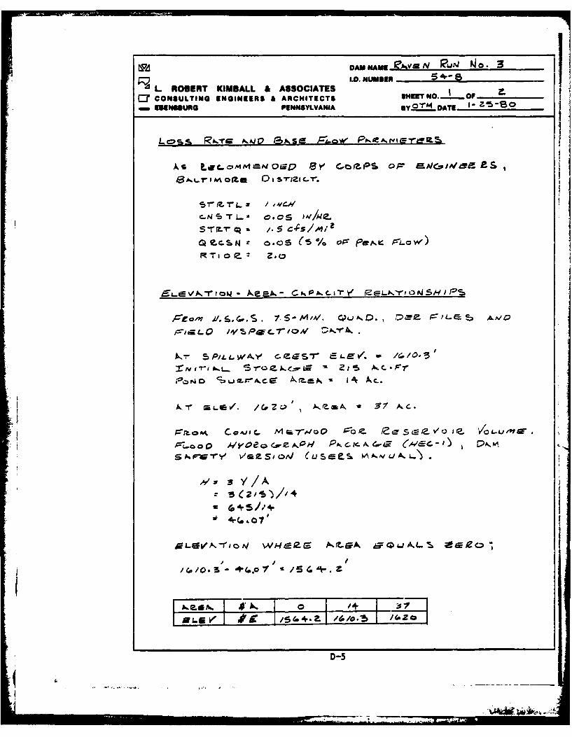
Lcss I'..T s 0 1 R 0 I2 ra.
'r"oi R.Tx/_ =Low)C V
RTo o.: Z.a
,5'm= r ow - sk "- c PA.c -,.-r Y LtDoN jp
ZI
,/. s/A
w (45//4
";s l'e, /o0.-'I -D -
I I'T I III il l i i i . ..... -5 .. - . o . . ,i , . . ~ ,r - I I I
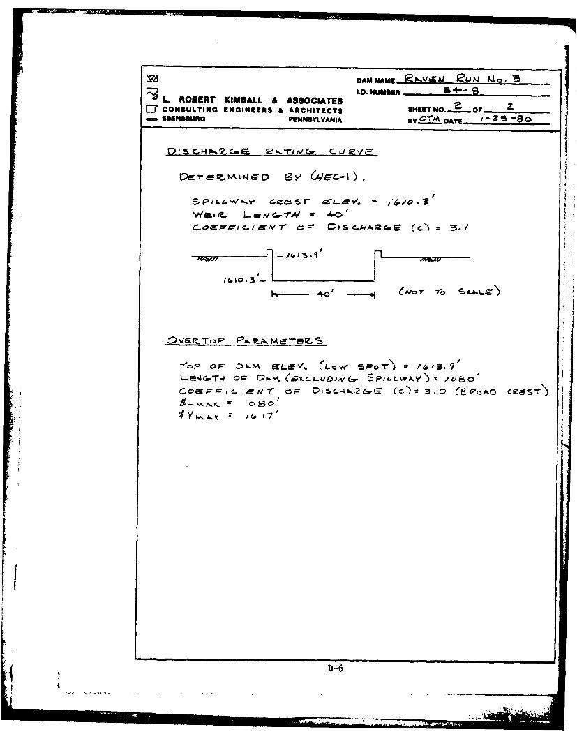
NODAMNAME Ia)6.V49AJ 12LiJ ~ 3
P ) I.D. NUMBER +sd L ROBERT KIMBALL & ASSOCIATES r. U
C7 CONSULTING ENGINEERS A ARCHITECTS SHEETNO. - OFEBENSBURG PENNSYLVANIA BY 0"22 DATE - - 8Z -80
t:::AII.J, D C-
".P / I L - .Ill . "f, cz = 4<o> .
.O ' lr-J=rA/r"0P !eSc.w/ ,Z¢E (c2..' = ./
=- , I. -6
c- 4A' Dic 4ia24 (Nov~ cecb
V It 7
I ID-6
.. I A
It
16-4.
.. o*'1 I
. O ---- I. -
0 ..
' - . .
.- 41 . - .
II~* 4- -- --. . -,. ,,< ,, _
-- :-- -4 "
+ e * . . 3 ... + . "'- *1 r:
+ ' ; +' , 4.--".t +;~ U++ a '
Z=. Z.I
r T.
-z 46
-z D
I~ z I
04 -
-D-
4l L'p

I- I .
CL Im
t .7 4-
92' ''06 D
4c V..
- -J 4
'is ' 4
I .- ~ '%CE
CL0
~ Ida
isw" 4 ll
wk.-
g Nt
P44
In*i 1* t.~ *'~* t* co
.. *Nq K.3k - - i
a *- ~ -*-
o -it' *~
S.~~i - 12

4Z:
P4 -
7~17
V4.
*x -
*us*~rd S.
-cc ;a,
At4
-A - .. h'-
APPENDIX EDRAWINGS

16
X0 d\.Pfitt , IiI.0
1700
suirur AirIDRA
5U-
T V
mo
Rui
0.6 MILES
Y
_u .
del- At I
RAVEN RUN DAMS NO. 2 AND N 0. 3
001111 STREAM EXPOSURE MAPscale I"s Road'
LHOSERT KIMBALL IS ASSOCIATESji E I COWAIING ENOWERS III ARCHTECTS
-~ ~ ~L.E Jaciei~w E* NN-
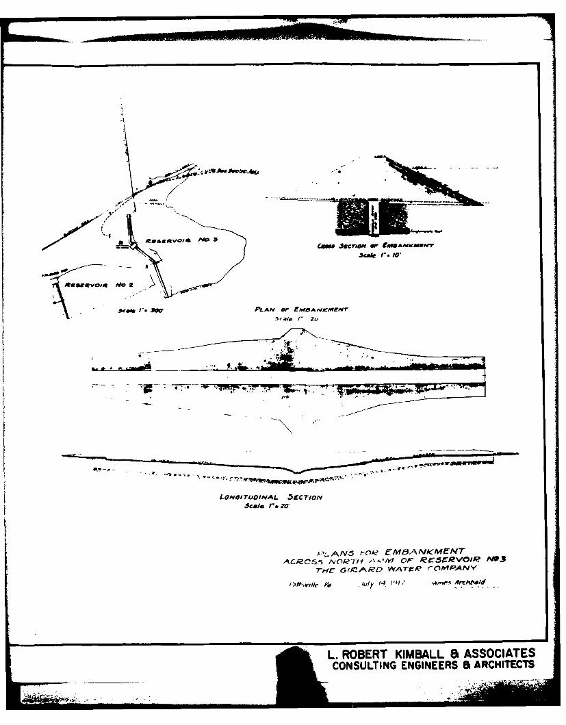
~~~ J~c#O &~ PLANOF NfBANAfEN
scile 1,. 1O
PLANN orO& E2M8AN,(M-VT
ACRCf5:5 Nnf,>V-f~' or ec-SCRVOIR N*3
T-Hr G'IOCARO WATEK? roMlPANY
L. ROBERT KIMBALL et ASSOCIATESCONSULTING ENGINEERS & ARCHITECTS
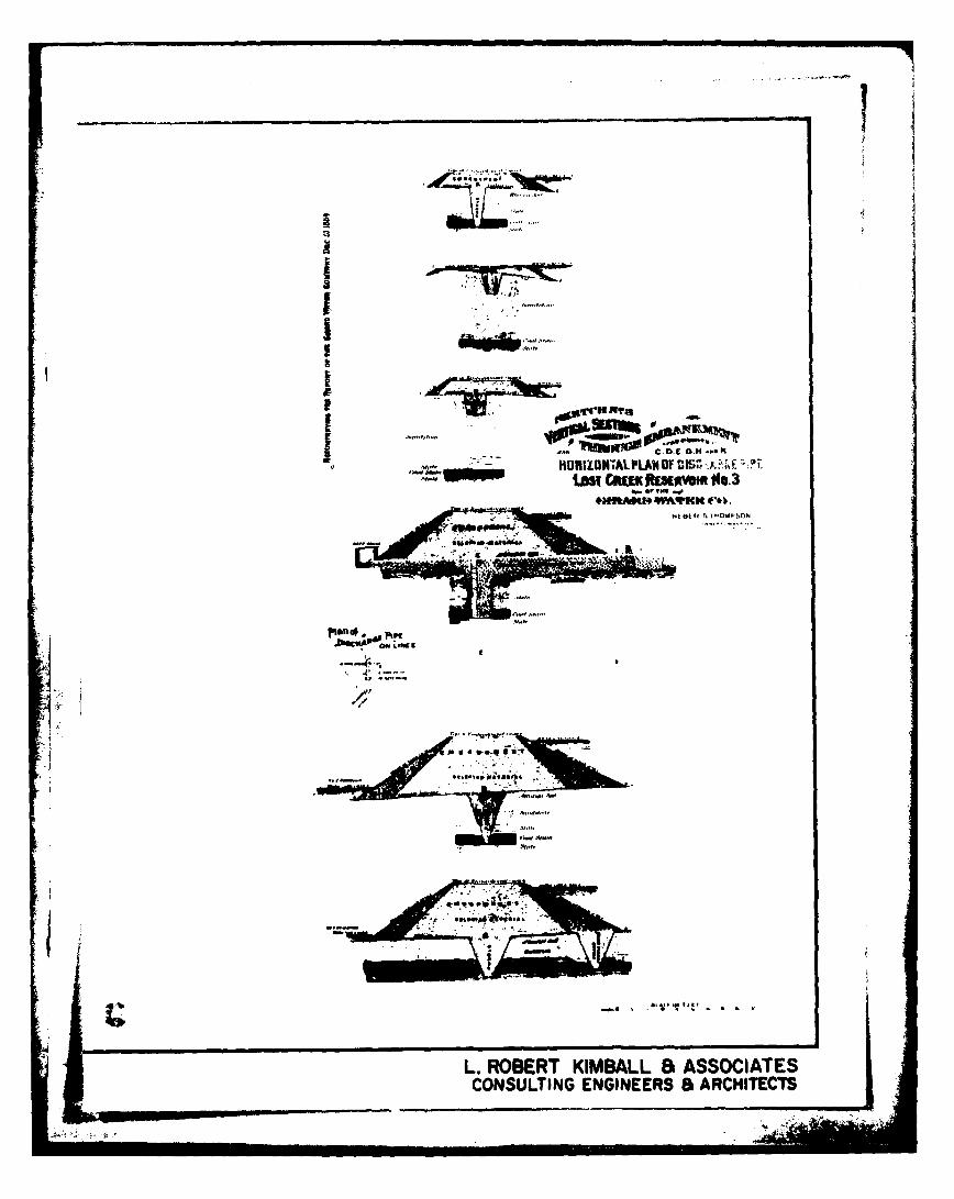
HOIZNALPLNOfDI's -rimi Ctaftmom 14A~ft9KN COPCI
L.RBR IBLL5ASCAECONSULTI ENGNES&ACIET

,. CALA5o rt ~er,.
F
14CC-2MP~rl~lnf tho *-P~rt 0,- the firr rfmm e 4 04.

TIM L
1ARDWATERC('.
L
L ROER KIBL -SSCAE
-NUTN ENIER a RHIET
-4dlom *OhIr*JW
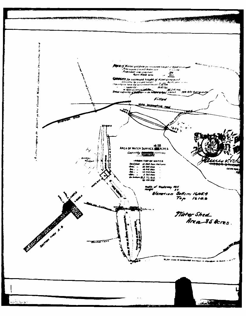
EM#,IWI~(~1Jdu ailV rj~vq'in'.
t p, it elf .Aa~~ g,~ E*IfMq
16.28SAREA OF WTE 3RFACLKACRE$
-wow 1wc £ Iave~i@n
~A FM1W
a. too *ItNW f 'kmI40
Arm..=.,. a

I-/
90
-aa
" RESERVOIR N9 3.
-" C' ' 0 -E x
L. ROBERT KIMBALL a ASSOCIATES -CONSULTI ENGINEERS & ARCITCT /
WARCHITECT
APPENDIX FGEOLOGY
Raven Run Dan No. 3 - General Geology
Raven Run Dam No. 3 is located in the Appalachian MountainSection of the Valley and Ridge Physiographic Province. Thisprovince is typified by numerous synclinal and anticlinalfeatures. Some minor faulting is indicated less than a mile tothe south of the dam. The bedrock underlying the reservoir con-sists of the Pennsylvania aged Pottsville Group and Post-Pottsville formation.
The Pottsville Group consists of light to dark gray, finegrained to conglomeratic sandstone, with lesser amounts ofshale, siltstone, coal and underclay. The bedding is generallywell-developed with sandstones and siltstones often cross-bedded. Joints are usually regular avd moderately well formed.The Post-Pottsville formation consists of light gray to brown,medium to coarse-grained interbedded sandstone and conglomerate.The bedding is moderately well developed while the Joints areregular and moderately developed.
Both deep mining and surface mining of anthracite coal hastaken place in the vicinity of this dam. The extent of any deepmining is unknown without extensive research.
P-
7__1
II in i i iR~i Ill.

I'Otsvll (roupt
J'rrom ,U~n ly .mndfunna n~ C(.lgiOflt
ANTACT RTATION
[ *~ 'fl~-Iu~zjvj~e ioPips""n
MISSISSIPPIA
''~' ~;s,' Fa SAL 1o5000