and hair-spring work · truing and poising balances. selecting, colleting, truing, vibrating and...
TRANSCRIPT

PRACTICAL BALANCE
AND
HAIR-SPRING WORK
WALTER J. KLEINLEIN
u

PRACTICAL BALANCE
AND
HAIR-SPRING WORK
WALTER J. KLEINLEIN

This edition, published in 1992 by Arlington Book Company, is an unabridged republication of the work originally published in 1925 by Walter J. Kleinlein, Waltham Mass. USA under the title "Practical Balance and Hair-Spring Work"
Limited Reprinting 500 Copies
ARLINGTON BOOK COMPANY 2706 Elsmore Street Fairfax, Virginia 22031-1409 USA Phone (703) 280-2005 • Fax (703) 280-5300
ISBN 0-930-163-46-X
P R A C T I C A L B A L A N C E
and
HAIR-SPRING WORK
By
WALTER J. KLEINLEIN
Author of "Rules and Practice for Adjusting Watches'
Copyright, 1925, by Walter J. Kleinlein
All rights reserved

Truing and Poising Balances. Selecting, Colleting, Truing, Vibrating and
Overcoiling Hair Springs
•
Preface
THE importance of the balance and hair spring as associated with fine watches is obvious. The requirement for understanding
combined with careful and skillful ability of the worker in handling the balance and hair spring is likewise obvious.
To the expert watchmaker who has a reputation for doing high-class work this book is not offered as something better but as something different and as something more directly applicable to the worker at the bench who desires to make himself more competent and more confident in this important par t of his work.
Demonstrations used in the text have been accumulated through years of personal instruction of those in training for both speed and quality of work, and the various operations are covered with strict attention to this detail.
The watch repairer seeking improvement in any feature of balance and hair-spring work may find just the information that will enable him to master the particular point that causes more or less difficulty in getting a balance true and in poise or in fitting a new hair spring, reforming an overcoil or truing a spring that has been damaged.
No at tempt is made to introduce mathematical or conflicting reference concerning various proportions of balances, or details of a scientific nature regarding hair springs, as these points delve into another phase of the mat ter in which the repairer is not so directly concerned.
The object is rather a desire to simply and clearly define and illuminate practical features that are associated with the daily work of the repairer to the extent of supplying detailed guidance from a fundamental standpoint which will be the means of actually enabling him to help himself and to do
in

more and better work with less effort and with greater commercial profit to himself.
Since the original presentation of the author's book — Rules and Practice for Adjusting Watches — many inquiries have been received for the same kind of practical bench-working information on the balance and hair spring, and this book is the author's effort in supplying this need. Shop detail is expressed in the same terms used in personal instruction, and systematically arranged in convenient form so that it may be available for immediate reference by the man at the bench in connection with his daily work.
WALTER J. KLEINLEIN,
January 21, 1925 Waltham, Mass.
IV
Contents PART I—TRUING AND POISING BALANCES
CHAPTER I Page
Tool Equipment 5 1. Details Covering Proper Calipers. 2. Tools Required for Bending the Rims in Truing the
Flat. 3. Tools Required for Bending the Rims in Truing the
Round. 4. Strength of Glass to be Used for Truing Balances. 5. Note on Above Remarks Covering Tools.
CHAPTER II
Observation and Detailed Practice in Flat Truing 11 6. Where to Begin in Truing a Balance. 7. Position of Calipers for Examination and Truing
the Flat. 8. Position of the Indicator for Truing the Flat. 9. How to Decide as to Which Rim is to be Bent Up
or Down. 10. The Next Step After Both Rims are Level at the
Arms. 11. Special Necessity of the Indicator Being Exactly
Above the Rim. 12. Force Required in Bending the Rims. 13. Difference Between Bending a Rim or Merely Pull
ing it Up or Down. 14. Proper Treatment for a Rim of the Above Descrip
tion. Why the Imperfection Nearest to the Arm Should
Always be Removed Before Attempting to Correct Other Imperfections.
CHAPTER III
Conventional Reasons and Examinations 17 16. Why Balances are Always Trued from the Top
Side of the Rim Instead of from the Bottom. 17. Why it is Necessary at Times to Move the Balance
Backward and Forward Instead of in One Direction when Examining the Light Between the Rim and Indicator.
18. Final Examination for True in the Flat.
V

CHAPTER IV
Observation and Detailed Practice in Round Truing 19 19. Advantages of Tools Described in Section No. 3
Over Other Methods for Correcting Imperfections in the Round.
20. Best Position of the Calipers for Truing the Round 21. Where to Begin in Truing the Round. 22. Why it is Necessary to Hold the Wrench Level
when Bending the Round. 23. Two Basic Balance-Truing Principles that Should
be Fixed in the Student's Mind.
CHAPTER V
Eccentric Pivots, Short-Arm Balances and Methods of Correction 25
24. Why Balances are Sometimes True in the Calipers and Not True in the Watch.
25. Definition of a Short-Arm Balance. 26. What Can be Done when One Arm is Shorter than
the Opposite. 27. The Best Method of Stretching a Short-Arm Bal
ance. 28. How Balances with a Slightly Short Arm can be
Trued without Stretching and How this can be Done in One Specific Way Only.
29. Explanation of the Result of Using the Wrong Method in Truing a Short Arm Balance.
30. How the Principle of Truing Short-Arm Balances Applies in General to Truing the Round.
CHAPTER VI
Fitting Screws — Effect of Temperature Variation on Truing Balances 33
31. How Balance Screws are Usually Fitted by Manufacturers of Fine Watches.
32. Why Certain Temperatures Should be Observed in Truing Balances.
CHAPTER VII
Special Methods of Detecting Slight Errors in Pivots and Truing of Balances 35
33. How to Detect Defective Cones and Balance Pivots. 34. Method Employed in Truing Balances and for
Final Inspection by Watchmakers on the Finest Foreign Watches.
VI
CHAPTER VIII Page
Poising Balances, Tools Required — Reducing Weight of Screws — Effect of Defective Pivots 37
35. Cause for Necessity of Poising Balances. 36. Tools Required for Poising Balances. 37. Usual Method of Reducing the Weight of Screws
in Poising. 38. Method Employed in Reducing the Weight of
Balance Screws by the Manufacturers of High-Grade Foreign Watches.
39. How the Balance Appears on the Tool When out of Poise, and What is Done to Obtain Poise. _
40. How to Determine When the Balance is in Poise. 41. The Effect of Flat Pivots on the Poise. 42. Action of the Balance on Poising Tool When Pivots
are Oval instead of Round.
CHAPTER IX
Poising Tool Better than Calipers — Making Alterations Without Disturbing the Mean Time 47
43. Why Better Work Can Be Done with a Poising Tool than with Poising Calipers.
44. Moving the Mean-Time Screws Sometimes Alters the Poise.
45. Making Corrections and Allowances ^ for _the Weight Removed from Balance Screws in Poising.
46. Effect of Out of Poise on the Time-Keeping Qualities of a Watch.
PART II — PRACTICAL HAIR-SPRING WORK
CHAPTER X
Practical Hair-Spring Work 53 47. General Suggestions. 48. Methods of Selecting Springs for Balances. 49. Colleting the Hair Spring. 50. Correct Form for Inner Coil of Hair Spring.
CHAPTER XI
Truing Hair Springs 64 51. Inspecting and Truing the Flat. 52. Inspecting and Truing the Round.
VII

C H A P T E R X I I
Vibrating or Timing Hair Springs 72 53. Some Factory Methods of Vibrating. 54. Methods of Repair Shop Vibrating. 55. Counting the Vibrations.
C H A P T E R X I I I
Overcoiling Hair Springs 79 56. The Gradually Inclined Bend for Raising the
Overcoil. 57. Short-Angle Bend for Raising the Overcoil and
Description of Tools. 58. Relationship of the Points of Attachment of the
Spring to Collet and Stud. 59. Attaching the Hair-Spring Stud. 60. Centering the Hair Spring on the Balance Cock. 61. Fit t ing a Hai r Spring Supplied by the Manufac
turer of the Watch.
PART I I I — S P E C I A L TOOLS A N D NOTES
C H A P T E R X I V
Special Tools and Notes J Q I 62. The Jacot Lathe for Finishing Pivots. 63. The Depthing Tool as Used for Truing and
Inspecting Balances. 64. A Scale for Comparing the Weights of Balance
Screws. 65. Finishers' and Adjusters' Method of Polishing
Balance Pivots in American Watch Factories. 66. Beat Blocks and Placing the Balance in Beat. 67. Impor tan t Details of Fit t ing a New Balance Staff.
VIII
Illustrations lit; . _ Page
1 Balance Truing Calipers 6 2 Indicator Grinding Disk 7 3 I lard Wood Truing Tweezers 8 4 Balance Bending Wrench 8 5 Extra Wide Slot Balance Wrench 9 (J Position of Calipers for Flat Truing 11 7 Position of Calipers for Flat Inspection 18 8 Position of Calipers for Round Truing 19 ') Position of Wrench for Bending the Round 21
10 Eccentric Cone Balance Staff 26 11 Balance Stretching Tool 28 12 Short Arm Balance Trued without Stretching 30 13 Short Arm Balance Improperly Trued without
Stretching 31 14 Jeweled Poising Tool 38 15 Balance Screw Undercutters 39 16 Shell Balance Screw Driver 39 17 Parallel Poising Pliers 39 18 Convex Bot tom Balance Screw 41 19 Screw Head Finishing Tool 43 20 Form for Selecting Hair Spring for Balance 56 21 Colleting Tool 58 22 Center Coil of Spring Bent for Collet 58 23 Flat Pliers for Forcing Collet and Stud Pins 59 24 Correct Form of Inner Coil Around Collet-Develop
ing to the Right : 61 25 ] Incorrect Forms of Inner Coil — Developing to the 2 6 ) Right 61 27 Hair-Spring Truing Calipers 65 28 Development of Inner Coil to the Left 68 29 Incorrect Sharp Bend at Point of Exit from Collet . 68 30 ) Incorrect Inner Coils with Diagram for Correction 31 J —Development to the Left 69 32 Standard Hand Vibrator 74 33 Gradually Inclined Overcoil 79 34 Overcoil Forming Tweezers 81 35 Diagram of Overcoil Curves 82 36 Overcoil Raising Tweezers 85 37 Ivory Tip Overcoil Raising Tweezers 86 38 First Bend of Short Anple Overcoil 87 39 Complete Short Angle Overcoil 87 40 Swiss Tacot Lathe 102 41 Depthing Tool as Used for Balance Truing 105 42 Balance Screw Weight Comparison Scale 107 43 American Pivot Polishing Lathe 109
IX

PRACTICAL BALANCE
and
HAIR-SPRING WORK
PART I
TRUING AND POISING BALANCES
General
THE work of truing and poising balances is a requirement of modern watch repairing that is frequently passed over lightly in the
instruction of beginners as well as by workmen themselves who have not given the matter suffi-i ient consideration.
As the tendency toward thin and small-model watches increases, however, the difficulties of the limited worker also increase, and he often realizes that something important is wanting in his ability, if for no other reason than that he finds less space available for wavering balances.
This is manifested in the fact that he has not as yet followed the proper instructions which would enable him to remove the kinks and true the balance flat and round in a few minutes' time.
To those who realize a weakness in performing this work, this book will prove a revelation after a few months of consistent practice, which is made easy by the daily opportunities that are afforded in the regular line of work. A little well-directed practice may save much time and difficulty in dealing with balances that run dangerously close to some associated part of the watch with the possibility of contact under varying temperatures, causing an extreme fast rate or stopping, with profound guessing as to the cause.
In fine wratches fresh from the manufacturers we find finely trued balances, and if the poise were examined it would also generally be found correct. Aside from the importance of these features is the interesting fact that the labor utilized in accomplishing such results is nearly always less than that utilized by many repairers in doing the work in a very unsatisfactory manner. A little concentrated practice in either flat or round truing
3

will demonstrate most convincingly that it pays to follow correct methods.
Perfect truing of balances and hair springs is a natural consequence when the work is handled by a trained workman, and it is one of the chief points of inspection tha t determines the class of work that the repairer will be allowed to handle in high-class establishments.
It is not merely a matter of appearance, for proper compensation demands careful truing, and the position and isochronal rates depend to a large extent upon the care used in poising the balance and then keeping it in poise as per the notes and suggestions in the chapter on poising.
To become expert in practical balance and hairspring work is to acquire a valuable asset, and it is earnestly desired that the details be not underestimated, but tha t they be carefully studied and applied to each day's work, as they are the necessary factors for simplifying much difficult work in the years to come, and it should be remembered tha t the hardest par t of one's work is always experienced during the period of learning.
To those who have had no experience whatever in the work it is suggested tha t each section be read and combined with actual practice until understood before proceeding to the next section.
4
C H A P T E R I
T R U I N G BALANCES
T O O L E Q U I P M E N T
1. Details Covering Proper Calipers
FIGURE 1 shows a cut of a good style of balance truing calipers. It should be quite heavy, and of sufficient stiffness to prevent springing
during the execution of hard bends of the balance arm. Jeweled jaws or bearings for pivots are not preferable, as they frequently chip or crack, and severely cut the cones. Hardened steel bearings about two and one-half millimeters in diameter and about three millimeters long are by far the most serviceable material that can be used.
The holes in which the pivots enter should be about eighteen or twenty one-hundredths of a millimeter in diameter, slightly counter-sunk and polished. This size will be found best for handling all of the larger-sized balances. These holes should of course be exactly in line with each other.
A horizontal hole about one millimeter in diameter should be drilled through the bearings close enough to the ends so that the cylindrical par t of pivots will be plainly visible when the balance is in calipers. This will prevent the pivots from becoming damaged through slicing or bending by coming in contact with the walls of long holes as the balance is placed in calipers, and will also be of some help in detecting bent pivots as well as making it easy to clean the pivot-holes and oil them from time to time.
The bar or arm bearing the indicator should move forward and backward with enough tension to hold it in any position, and should not become either loose or tight in action. This can be^at-
5

Truing and Poising Balances
tained by means of a split washer under the screw head as shown in Fig. 1.
Fig. 1
The indicator should be made with double pointers and constructed so that shifting in any direction may be accomplished with slight pressure of the tweezers. This is very important to repairers because the indicator requires expert setting every time a different length staff or size of balance is trued. It should be about one millimeter in thickness and have a slight curve on the ends for truing the round. The lower part of indicator should be ground flat and have a hollowed out section about one millimeter from the end to allow clearance for balance screws. Pressure with the tweezers at "A" or "B" , Fig. 1 should lower or raise the entire indicator. The arrow at " C " points to a round pin on which the end sector shifts with slight friction.
A soft metal disk in several sizes (the largest to be about the size of a sixteen size balance) should be provided for final grinding and finishing of both the flat and round surfaces of the indicator for obtaining the best light results on the various sizes of balances. Each disk should be staked to a staff
6
Truing Equipment
ol about the same length as usually found on balances of its size. Fig. 2 shows a correct size di k for the larger balances.
The disk should be coated with oil-stone powder and oil, then placed in calipers and moved forward and backward, while the indicator sector to be ground to form is held firmly against it. For truing the balances of very small wrist watches an extra calipers and disk to correspond will be required.
= $ = Fig. *
Several styles of calipers are on the market, but they are seldom ready for immediate use as the price paid does not admit of very close refinement of the above features.
Any time or expense assumed however in perfecting these details is well invested, as they will last for a lifetime and make it possible to do the work so much better than can be done with calipers that are only roughly finished.
2. Tools Required for Bending the Rims in Truing the Flat
Much of the flat truing is done with the fingers, although it is not possible to do it all in this way. Short bends, for instance, require something smaller than the fingers, especially in the case of stiff balances that are to be finely trued. One of the most useful tools for the purpose is a tweezers made of hardwood, as shown at slightly undersize in Fig. 3. A tweezers of this description will remove almost any kink, is easy to make, and will not mar the finish on the top of fine balances. It sometimes occurs that a balance is especially hard, and the rims will not yield to either the fingers or
7

Truing and Poising Balances
the tweezers, and in such instances the rim may be held in a smooth-jawed parallel pliers and the rim can then be bent with the fingers.
Fig. S
3. Tools Required for Bending the Rims in Truing the Round
For this purpose a tool made of brass or nickel wire and containing slots of various widths is necessary. The sharp corners of the slots should be removed, to prevent marring the sides of balance rims.
Fig. 4 shows a tool of this description with two slots on each end; the narrowest slot is five-tenths of a millimeter in width and one millimeter deep. Each other slot is wider than its predecessor by about five one-hundredths of a millimeter, and about one-tenth of a millimeter deeper. The wire used in making this tool should be about six millimeters in diameter, with the ends filed flat to about eight-tenths of a millimeter in thickness. For convenient handling it should be about 3\ inches long.
Truing Equipment
I n some instances balance screws are closely assembled, and it may seem necessary to remove a screw for making a bend in the round. This can be avoided, however, by having an extra wrench or tool with cuts wide enough to fit over both the rim aiid head of the screw. All ordinary bends can be made in this way with ease and safety.
Fig. 5 shows an undersize tool of this description which should be made of the same stock as per dimensions given for Fig. 4. The smallest slot to be about one millimeter wide and one millimeter deep, each subsequent slot to be about two and one-lialf-tenths of a millimeter wider and one-tenth of a millimeter deeper.
=ca
fir I I ̂ Fig. 6
4. Strength of Glass to be Used for Truing Balances
A fairly strong glass should be used for practicing fine truing, and after becoming familiar with close work it is best to use a medium two and one-half or three-inch glass and a stronger glass for inspection. The normal eye should have an opportunity of resorting to a stronger focus glass in later life when it may be needed.
5. Note on Above Remarks Covering Tools
The preceding remarks covering tools and the following details referring to positions of calipers, setting of indicator, examination of light between in-
9
« » r ' — k -

Truing and Poising Balances
dicator and rims and the points covering exact methods of making bends should not be passed over lightly but should receive serious consideration, for the attainment of success and ease in doing the work will be the reward.
10
CHAPTER II
OBSERVATION AND DETAILED PRACTICE IN FLAT TRUING
6. Where to Begin in Truing a Balance
The proper place to begin truing a balance is of the utmost importance, for if a wrong start is made it may take even an expert several times as long to finally get it true. This important place is always in the flat, and in every instance the first point to examine is the condition of the two rims, directly over the arms in relation to equal heigh t.
7. Position of Calipers for Examination and Truing the Flat
The calipers should be held in the left hand at an angle of about 45°, and with the end holding bal
ance toward the eye. The back end of calipers should rest firmly on the bench, and the front end should be supported by the left thumb which should be between the calipers and the bench.
As the eye should in all instances be a few inches above the bench, the work will be at an angle which will permit of instant raising or lowering for better light results. Fig. 6 demonstrates position of indicator and balance as it should be seen. The arrow pointing to the light be-
Fig. e tween indicator and balance rim.
8. Position of the Indicator for Truing the Flat
The indicator should be set so that there is a distinct space of light between it and the flat of
11

Truing and Poising Balances
rim directly over one of the arms. Then carefully note the amount of light and turn the balance so that the opposite rim will be under indicator(— at this point of instruction your attention is specially called to the importance of holding the head steady, as well as not moving either bar or indicator in the slightest degree, as otherwise the examination will be faulty —) this will immediately show as to whether one rim is lower than the other.
9. To Decide as to which Rim is to beBent Up or Down
If the light is not equal over both arms, sight under the balance and see if it is possible to detect whether either arm is bent up or down from the true level. This will often decide which rim is to be worked on first; bu t if the variation is very slight the decision is made entirely by the indicator, and as a rule the rim to be trued first is the one which shows the greatest variation from true over its entire surface. After making this decision, turn balance to the right so that the rim to be bent is clear of the indicator and hold calipers firmly in the flat truing position as per Fig. 6, and with the tweezers placed over rim at the arm make a bend either up or down as may be required. Then place the indicator exactly over the rim above the arm and examine again, and if the first bend does not level the rim, try again until successful.
Sometimes the tweezers can be eliminated and the thumb of right hand can be used in pushing the rim up at the arm, or the thumb together with the forefinger of the right hand, can be used in bending it down. A stiff balance generally requires a little of both methods to get it perfectly true, and a balance loose on staff will move so easily that it can readily be detected in the process of getting both rims exactly level at the arms.
12
Observation and Practice in Flat Truing
!<). The Next Step after Both Rims are Level at the Arms
Begin at one of the arms, or rather, at the end of I lie small segment which extends beyond the arm, I urn balance slowly and examine the light be-ivveen indicator and rim over the entire length out to the cut or free end. The first indication of cither more or less light will demonstrate the spot to begin truing the rim either up or down. This brings out the important point tha t the examination and truing should begin at the end of the rim which is joined to the arm. At no time should a correction be made out toward the free end of the rim until the indicator shows that the rim is perfectly level from the arm out to such point.
In the case of long sloping kinks or bends the tweezers or the fingers should be placed beyond the I x )int where the slope begins; not exactly at the point, because the tension would cause the actual bend to extend too far back of where it is wanted. This is very important, and should not be overlooked. A balance rim having short, wavy kinks should lie trued with the tweezers only, and the kinks ran be best removed by holding the tweezers at an angle and using the edges, rather than by placing it flat over the rim. In this way short kinks can be removed easily.
When one rim has been trued, the opposite should be handled in the same manner, always beginning at the end attached to arm and removing each kink regardless as to how much it throws the further end of rim up or down. Truing one rim will sometimes disturb the other, and it is necessary to go over each rim a second or third time before any at tempt is made to true the round. In such cases it should be necessary to merely push the rim either up or down to get it correct again, for if the kinks have been removed in the first truing they will not return, although springing up or down cannot be avoided by even the best of truers.
13

Truing and Poising Balances
11. Special Necessity of the Indicator being Exactly Above the Rim
The light will be very deceiving if the flat par t of the indicator is not directly over the flat surface of the rim and if it should be one or two millimeters inside or outside of the rim it will be almost impossible to get results, as the slightest variation of the eye or calipers, will change the proportion of light. Lack of attention to this detail always causes difficulty in truing as well as loss of time in getting the work done.
12. Force Required in Bending the Rims
Considerable finger strength is sometimes necessary in making bends such as forcing one rim up or down at the arm, and one should not feel discouraged or lose confidence because these bends are not made successfully at the first few at tempts. Experiment deliberately and with confidence, and use only slight pressure on each balance to begin with.
If the first bend does not give results, bend harder the next time, as the balance may be of a stiff nature and require more bending than a soft one would. By using moderate force the first time you will be sure that rim will not be bent too much, in case the balance is of a soft nature. Most watchmakers can tell from experience on various kinds of watches as to the particular models that have soft balances as compared to those having stiff balances, and this knowledge is of considerable assistance in making the necessary bends.
13. Difference Between Bending a Rim or Merely Pulling it Up or Down
Before entering upon the details of truing the round we will consider the difference of bending a rim or merely pulling it up or down, as this always
14
Observation and Practice in Flat Truing
. m i s to be a "st icking" point in direct teaching "I ilie work, and for this reason two contrasting examples will be analyzed.
1'resume a rim sloping gradually downward 11mil the end tha t is fastened to the arm out to l lie free end. This rim simply requires pushing ilie free end upward with the thumb or lifting it with the tweezers to make it fairly level.
As a contrasting example presume a rim tha t is i trifle low at the fixed end and gradually slopes
upward ou t to about the center and then slopes downward out to the cut. Actually this rim would be low at both ends and high in the center, and no amount of pushing up or down would make it level. It would act similar to a see-saw, pushing the fixed end up level will cause the free end to become considerably lower and in turn pushing up the free end, will cause the fixed end to become lower and this will continue until a distinct bend is made.
14. Proper Treatment for a Rim of the Above Description
The proper treatment for a rim of this kind would be about as follows: First bend or push up i lie rim at the fixed end until it is level, then examine it with the indicator to find how far it is level from the arm. This will most probably be about to the high point previously found at the center, and from this point to the end a noticeable downward slant will be apparent. T h e correct bend at the proper place here will get immediate results. The calipers should be in the correct position for Hat truing, as per Fig. 6, and then with the truing tweezers held in right hand grasp the rim so tha t side of tweezers toward yourself will be exactly at the point where the rim starts downward, and make a sharp bend by twisting the further side of tweezers upward. This should be accomplished with
15

Truing and Poising Balances
just as little pull upward or downward as possible, and practice until one is capable of correctly making this bend will go a long way toward truing many balances.
After making this bend replace the indicator over the rim above the arm and examine from the very beginning of the rim out to the cut. It is quite certain that this one application will not have proved sufficient to make the rim perfectly true, even with the most expert workman; all tha t can be expected up to this time is improvement. Invariably the same process of bending will have to be gone over again, only to a lesser degree, as in making the bend as described, the strength used in bending nearly always tends to force the rim downward at the arm.
After the second application of this bending the rim should be in such a condition that by merely pushing it up with the thumb of right hand or pulling it down with thumb and forefinger the desired condition will be obtained.
15. Why the Imperfection Nearest to the Arm Should always be Removed Before Attempting to Correct Other Imperfections
For the same reason that pertains to all things that are correctly constructed; namely, the principle of beginning at the base and building upward instead of in the middle or at the top, and in the case of truing a balance the end of segment attached to the arm forms the base, and the truing must begin there and proceed to the end tha t is free.
16
C H A P T E R I I I
CONVENTIONAL REASONS A N D E X A M I N A T I O N S
16. Why Balances are Always Trued from the Top Side of the Rim Instead of from the Bottom
This may seem to be an unnecessary question, but nevertheless it has been asked at various limes by students who had been repairing watches lor several years. The reason is because the two sides are not always parallel or, in other words, the rims are not always of an exact width at all points, and as the top side is the one observed in running or in inspection it is always made true, and any error in width is thereby placed on the bot tom side where it will not interfere with appearance.
17. Why it is Necessary at Times to Move the Balance Backward and Forward Instead of in one Direction when Examining the Light Between the Rim and Indicator
In some instances it is quite difficult to detect a slight error by moving the balance steadily in one direction from the arm to the free end, even when the indicator and all conditions are proper. A ^reat deal of benefit will be obtained by shifting the balance forward and backward about one-fourth of an inch and closely observing the light between indicator and rim. Practice in this point will detect variations that may escape otherwise, and it should be applied over the entire surface of both rims.
18. Final Examination for True in the Flat.
The final test as to the quality of the flat truing should be made by having the calipers slanted back
17

Truing and Poising Balances
on the bench slightly so that the light between indicator and rim can be seen as shown at "A" Fig. 7. Hold calipers steadily with the left hand and open them slightly so that the balance is just free enough to spin when touched by a camel's hair brush, and while it is spinning slowly (not fast) observe the top edge of rims with the strong glass and see if any waver can be noticed. If not, it can be passed for the present, and truing of the round is next in order.
Pig. 7
One very important feature that is not to be forgotten in the examination of the flat while balance is spinning slowly in calipers or running in the watch is the fact that the balance screws are not always in line, and the eye must be trained to observe the flat of rim only, so that confusion will not occur because of this fact or because the screws may be of irregular diameter which causes a wavy appearance when the rims may be perfectly true.
18
CHAPTER IV
OBSERVATIONS AND DETAILED PRACTICE IN ROUND TRUING
1(>. Advantages of Tools Described in Section No. 3 Over Other Methods for Correcting Imperfections in the Round
After the rims have been well trued in the flat we m.iy proceed with truing the round. The bending wrenches described in section No. 3 have distinct advantages over tweezers, pliers or the fingers for general use, as a slot can be used which is just a i rifle wider than the thickness of the balance rim. The leverage obtained through this tool admits of more quickly and more permanently removing small or large kinks because of the opportunity of placing it between the screws.
The wide-slot tool takes care of those instances where the screws are closely assembled, and if the < omers of the slots are properly removed, there is less danger of marring the balance rim or screws than there is through the use of tweezers or other instruments.
10. Best Position of the Calipers for Truing the Round
The calipers should rest firmly on the bench with the top side slightly tipped toward the operator.
Fig. 8 demonstrates the position of indicator and balance rim as they will appear when calipers are held in the proper position, the arrow " B " pointing
to the light between indicator and circumference of the rim. The angle at w h i c h calipers are held can be changed to suit
19

Truing and Poising Balances
the convenience of the truer, and is governed more or less by the position assumed by him at the bench. In most instances when the proper position is assumed by sitting low at the bench the angle is about 45 degrees.
21. Where to Begin in Truing the Round
The examination or truing of the round should begin at the fixed end of one of the rims, and the indicator should be placed so tha t light is plainly visible between it and the rim, with the indicator just high enough so that there is no danger of it rubbing on the balance screws.
The indicator should not be too close to the rim so that it will blur the light or scratch the rim and also not far enough away so tha t small errors cannot be detected. Begin at the end of small segment extending beyond the arm, and move the balance slowly, so that the free end will advance toward the indicator. If the light is not exactly the same at all points, turn balance so tha t rim to be bent is free from indicator and place the bending wrench on the rim at the proper place (See Fig. 9) and sway it sideways with enough force to bend the rim either in or out at the point where the first indication of change of light is noticed.
While examining the light between indicator and rim, neither the indicator, calipers or the eye should be shifted, because any slight change of position while examining will cause the light to vary even when the balance is perfectly true.
If the light is not equal between indicator and rim over the small section that extends beyond the arm, then this should be made true before proceeding to bend any other part of the rim. If it is found tha t this small sector curves inward and the rest of the rim extends outward beyond a true circle, it will be necessary first to bend out
20
i rations and Practice in Round Truing
!- small sector and then make a sharp bend in-ii d on the opposite side of the arm. I n using the bending wrench a slot should be
< 11-<-ied that fits quite freely, b u t not so freely tha t i lie corners of the slots will mar the rim.
After making these bends examine the small •.cctor and an equal section on the opposite side of .inn and if the light is equal, proceed to examine ilie rim out further until the next point that requires bending is located, and after making a bend l ine, test again with the indicator from the very I x-ginning of the rim and continue this until the i im is true, bu t not overlooking the point of set-ling the indicator, and beginning the examination ,ii the end of the rim attached to arm each time a licud is made.
When one rim has been trued, proceed to the next and use the same methods as with the first iiin. There is some difference in placing the wrench in position for making bends in the round compared to placing the tweezers for bending the Hat. It will be noted that in truing the flat it is advisable to place tweezers beyond the point where the bend begins. In the round it is advisable to place the wrench slightly nearer to the a rm than the exact point where the bend or kink begins. This is because the slot in the wrench is more rigid than the tweezers, and the tension will not extend back of the point of contact. It is more probable tha t the out-of-true condition will be
made worse by having the wrench forward of the point where the kink begins. Fig. 9 shows a balance rim with a severe kink, and the wrench in position for making the first bend. T h e calipers should be resting
Fig-9 on the bench so that the balance and indicator will appear similar to Fig. 8
21

Truing and Poising Balances
(Page 19) with kinked section of rim just opposite the indicator. Then firmly draw the bending-wrench toward yourself until the kinked par t is bent outward.
It may be necessary to move the wrench forward slightly in making several applications of the bend, and after the kinked section is made true the par t beyond the kink will extend considerably outward beyond the true circle, and it will be necessary to place the wrench at point shown by arrow (Fig. 9) and bend it inward to obtain perfect concentricity of the rim.
22. Why it is Necessary to Hold the Wrench Level when Bending the Round
It is necessary to hold the wrench level when making bends in the round so that throwing the flat out of t rue will be avoided as much as possible.
At best it will be unavoidable to prevent the flat from getting somewhat out of true when making pronounced bends in the round. This, however, is easily remedied by a slight bend in the flat with the truing tweezers or by pushing the rim up or down in the usual way.
In case tha t the bends in truing the round are made with an upward or downward twist, it will require extra bending to get the flat true again. At any rate , it is always imperative that the flat be true before a successful test of the round can be made, and each time that the flat is re-trued it will again be necessary to go over the round. This detail is called "touching u p " by expert balance-truers, and the number of times required to touch up both round and flat depends upon the experience of the truer.
An expert would expect final results after the second touching up, and would most probably not spend over five or ten minutes on the most difficult job, while an inexperienced truer might easily
22
crvations and Practice in Round Truing
I'ciid an hour on the same job and then not get in:-t-class results.
As a rule balances of high grade watches tha t li.ive not been mishandled will require only a touch-up process to get fine results, bu t the experience • Mid practice in truing must be back of the workman to enable him to do this touching-up properly • Mid it should not require more than a few minutes in true any balance tha t has had a staff changed or which has been mishandled and make it as true as w hen it left the factory.
' 3 . Two Basic Balance-Truing Principles that Should be Fixed in the Student's Mind
If the student, through reading up to this point, has two things firmly fixed in his mind, he has gained some important knowledge. The two references are that the flat must always be trued before the round, and that both rims must be t rue and absolutely level with each other to the slightest degree directly over the arms. This is the founda-lion upon which the final truing must be based, and is also the most difficult feature for many repairers to comprehend.
To comprehend this more thoroughly, presume that the small segment extending beyond the a rm is a trifle high in the flat and slants downward to an equal distance on the other side of the arm and from there out to the cut the rim is perfectly level with the opposite rim. Apparently four-fifths of the rim is perfectly true and the first fifth is not true.
It will be evident that the time spent in truing this rim has been lost as in bending down the small par t of rim at the arm the entire four-fifths of rim will be out of true again and require the same work as though it had not been trued. The round in such instances always requires retruing because bending a rim down at the
23
Truing and Poising Balances
arm increases the circumference and bending it up decreases the circumference at tha t point.
If this small section out of true had been the latter one-fifth of rim at the free end, the mat ter would have been simple, as it could have been bent down without disturbing the round or flat previously trued, while the method pursued was entirely contrary to principle, and prevented results from the very moment that this point was overlooked.
24
C H A P T E R V
!( C E N T R I C PIVOTS — S H O R T - A R M BALANCES A N D M E T H O D S OF C O R R E C
TION
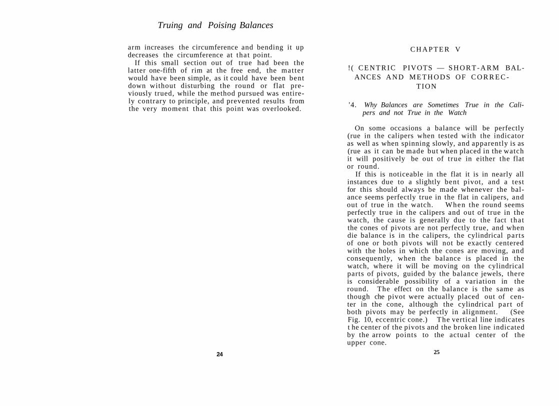
'4. Why Balances are Sometimes True in the Calipers and not True in the Watch
On some occasions a balance will be perfectly (rue in the calipers when tested with the indicator as well as when spinning slowly, and apparently is as (rue as it can be made but when placed in the watch it will positively be out of t rue in either the flat or round.
If this is noticeable in the flat it is in nearly all instances due to a slightly bent pivot, and a test for this should always be made whenever the balance seems perfectly true in the flat in calipers, and out of true in the watch. When the round seems perfectly true in the calipers and out of true in the watch, the cause is generally due to the fact tha t the cones of pivots are not perfectly true, and when die balance is in the calipers, the cylindrical par ts of one or both pivots will not be exactly centered with the holes in which the cones are moving, and consequently, when the balance is placed in the watch, where it will be moving on the cylindrical parts of pivots, guided by the balance jewels, there is considerable possibility of a variation in the round. The effect on the balance is the same as though che pivot were actually placed out of center in the cone, although the cylindrical par t of both pivots may be perfectly in alignment. (See Fig. 10, eccentric cone.) The vertical line indicates t he center of the pivots and the broken line indicated by the arrow points to the actual center of the upper cone.
25

Truing and Poising Balances
Balance staffs having cones of this description are by no means unusual, although serious instances are not often found in watches of high grade, and when one is found in a watch that is intended to be a very close time piece it should be changed or the cone recut, as it is seldom possible to true the balance so that it will give best results in the watch, even though it is possible to make it look true in calipers.
The only way to make it look true in the watch would be by employing the depthing tool method described in Section No. 34, also in Part III, Section No. 63.
25. Definition of a Short-arm Balance
Fig. 10 In truing the round, instances
will sometimes be found when the two arms are not of equal length. Such cases are known as short-arm balances, and the light will not be exactly the same between the indicator and rim at both ends of arm. Such balances require special treatment, compared to the regular balance. Before doing any work, however, it must be certain that both rims are perfectly level and true in the flat, for if one rim is slightly lower than the other at the arm it will appear longer in the round when examined with the indicator.
Should this be the case, it should be trued up level with the other rim after which both arms may be found to be of equal length. Likewise, if one rim is trued slightly higher at the arm than the rest of the balance, it will appear shorter when ex-
26
/Eccentric Pivots — Short-Arm Balances
i mined with the indicator. This point is men-lioned specifically as an important detail to prevent unnecessary work and probable damage to i lie balance by unnecessary stretching.
:>.(). What Can be Done When One Arm is Shorter than the Opposite
If one arm is really shorter than the other, there arc several methods that may be considered for correction; turning the balance half-way around on the staff, changing the balance, stretching the short arm or truing the balance as nearly perfect as possible are means of covering up this defect.
Turning the balance half-way around on the staff will sometimes show improvement, due to the fact that the staking shoulder may be eccentric or not fitted closely to the hole in balance.
Changing the balance can only be resorted to by the repairer in extreme cases, and is out of the question from a commercial standpoint unless the condition is beyond correction.
Stretching the short arm is a more common occurrence in factories, as well as by expert repairers, and is often the only means of saving the balance and getting it true. For stretching two methods are available, either the use of a cutting stretcher or a flat stretcher.
The cutting stretcher should be made of tool steel about two and one-half inches long and three millimeters in diameter; one end should be finished off at an angle of about forty-five degrees and filed flat on the back or long side to a dull or rounded cutting edge that will be wider than the arm and fit up close to the inside of rim (See Fig. 11). It should then be hardened and polished to make a clean cut. The balance arm should be resting on a solid steel block and stretcher held perfectly upright to produce a cut of equal depth across the entire width of the arm.
27

Truing and Poising Balances
Stretching of this description should only be considered for the lower grades of unadjusted watches which sometimes have considerable error of this description. Care should be exercised not to cu t too deep, as the balance can easily be ruined by weakening the arm too much. Some watchmakers do this stretching out toward the center of the balance so tha t it will be under the hair spring. If the cut is slight, however, it will not be noticed if made close to the rim, and as neither location is correct for a high-grade watch, one may be considered as commendable as the other.
A stretcher that fits the staking tool can also be used, and in instances where the arm of balance is located halfway between the top and bottom of the rims, the arm should always rest on a s tump for support directly under cutt ing edge, as otherwise the arm may be badly bent.
27. The Best Method of Stretching a Short-Arm Balance
The method of stretching the arm with a flat punch is by all means the best, for it does much neater work and practically eliminates the danger of injuring the balance. This requires a staking-tool set having well-tempered punches and s tumps such as are found in all high-grade staking outfits; the punch and stumps should be large enough in diameter to cover the width of the arm and both surfaces perfectly flat.
The arm to be stretched should be placed between the punch and stump with the rollers nearest
28
'-Acentric Pivots — Short-Arm Balances
;< punch. Strike the end of punch several times M(!I the hammer, then true the flat and test the iniis for equal length again in the round. If it
; . i s not stretched enough repeat the operation at a l xiint nearer the rim of balance.
11 will be difficult to find where this stretching lias taken place, but consideration should be riven to the fact that some arms are thinner .iml some softer than others, and the force to be applied in striking the punch is to be determined only by practice.
'.8. How Balances With a Slightly Short Arm can be Trued Without Stretching, and How this can be Done in One Specific Way Only
Truing the balance by means of covering up or hiding the short arm is quite an ar t that is practiced by all professional balance-truers, and with considerable success when the error is slight. Anyone who can t rue an equal arm balance can as easily true a slightly short-arm balance without stretching if the correct method is followed.
If it is possible to make a short-arm balance look as true when in the watch as one with equal arms, it can only be accomplished in one way, and tha t is to true the rim on the long arm perfectly concentric, then with the wrench bend out the short segment that extends beyond the arm on the short-arm side. Next place the wrench on opposite side of arm and just as close to the arm as possible, make a bend tha t will throw the rim outward. The object of this is to get the rim on the short-arm side concentric with the rim on long-arm side from a point just as close to the arm as possible. When this is accomplished, the only par t of the entire circumference that will not be t rue is that par t directly at the end of the short
29

Truing and Poising Balances
arm, and it will take a very expert examination to detect the error.
It is essential tha t the details of this operation be carefully followed, and tha t a correct understanding of the principle be had by the workman, and for tha t reason the mat ter will be considered further. The unskilled truer invariably wants to know why the rim on the short-arm side cannot be trued concentric and the long arm trued inward to conform with the short arm,
It will be noted that this is exactly in reverse of the above instructions, and the difference between this and the proper method is the difference between making it possible to true the balance or not to true it. If the balance is trued as per instructions there will be one spot that is not perfectly concentric. This refers to the small section directly at the end of the short arm, and careful examination with the indicator discloses the fact that there is a trifle more light at this spot.
When the balance spins slowly in calipers or oscillates in the watch, this small spot of light will not be visible nor cause any jump in the round. This is due to the fact that no particle of metal extends beyond the true circumference of the bal
ance. The error being merely a slight depression in the circumference that can be detected only with the indicator. See Fig. 12 for an exaggerated example of a short arm balance properly trued by this method. " A " indicating the short-arm segment which is
Fig. it not concentric.
29. Explanation of the Result of Using the Wrong Method in Truing a Short-Arm Balance
In case tha t the short-arm rim is trued concentric and the long-arm rim is trued inward from a
30
Eccentric Pivots — Short-Arm Balances
IMlint near the arm, the result would be that the < ii tire circumference of the balance is true except tin- small spot at the end of the long arm, and examination with the indicator will disclose that there is lrss light here than at any other point of the cir-( n inference. This indicates tha t instead of a ••light depression of the rim at one end of arm there is a convex segment.
The result because of this segment of solid metal extending beyond the perfect circle will be a jump in
the round when running in the watch or spinning slowly in the calipers, the jump appearing each time that the segment passes the point upon which the eye is focused, and a balance trued this way cannot possibly appear perfect.
For an exaggerated example of a short-arm balance trued in the wrong way see Fig. 13, " B " indicating the long-arm segment which is not concentric and from which point the rim should have been bent out.
30. How the Principle of Truing Short-Arm Balances Applies in General to Truing the Round
The principle applied to truing short-arm balances is useful in the general truing of balances in 1 lie round, and after the workman has reasonable experience in fine truing he will find that if one or both rims have a tendency to be trued inward very slightly near the cut, the balance will look much better when in the watch than would be the i ase if one or both rims were trued outward to an '•cjiial degree. This does not place the s tamp of approval on truing rims inward from the true con-< entric, but the point is mentioned for the purpose nf assisting in the detection and correction of slight wavering in the round.
31
Fig. IS

Truing and Poising Balances
To understand just where a slight error will not be apparent in running appearance is also of great importance in learning to do balance truing quickly.
32
C H A P T E R VI
i 1TTING SCREWS — E F F E C T OF T E M -I 'KRATURE VARIATION ON T R U I N G B A L
ANCES
3 1. How Balance Screws are Usually Fitted by Manufacturers of Fine Watches
The mean time screws should always be examined before truing, to be sure t ha t they are not light enough to destroy the truing in case they are turned either in or out in timing the watch.
Among manufacturers of very fine watches it is ;i rule to turn out all balance screws about one tu rn and then turn them back in place at as near equal I fusion as possible before truing. The reason for lliis is that some screws are originally set up very tight against the rim, while others may be set in place with less force, and when a tightly-bound : < rew is removed later in poising and replaced with less tension, there is considerable possibility tha t the rims may spring slightly and disturb the truing of the round.
It is not expected that the repairer shall t ry every balance screw in this way, bu t he should use care in replacing screws that are removed in poising so that they will have reasonably proper tension.
32. Why Certain Temperatures Should be Observed in Truing Balances
Best results are obtained by truing balances in about normal temperature or between sixty-five and seventy-five degrees Fahrenheit, and the inspection for true should be made at about the same temperature in which the truing was done. The rims will vary slightly with changes of tempera-
33

Truing and Poising Balances
ture because of the fact that they are expansion balances and cannot be expected to remain true in all temperatures. This is quite important in cases where the truing has been done in the evening with a possible temperature of seventy-five degrees and the following morning may be only sixty degrees. The balances may not look true in the morning, bu t if the inspection is made several hours later, with a rise in temperature, the rims will be found to have returned to the position in which they were trued.
34
C H A P T E R VII
IM-XIAL M E T H O D S O F D E T E C T I N G I I G H T ERRORS I N PIVOTS A N D T R U I N G
OF BALANCES
.\.\. How to Detect Defective Cones and Balance Pivots
The most simple method of testing the cones for d u e is to have a light calipers (similar to those used for truing hair springs) with very small holes HI the ends, just deep enough to prevent balance I mm dropping out of calipers when it is spinning II <-ely. This will allow a clear view of the cylindri-( al par t of pivots as well as the cones. Then rest calipers firmly on edge of bench with staff in horizontal position and balance free from any obstruction, slightly above the bench, and left hand hold-in g opposite end of calipers and controlling the I medom with which balance turns.
Spin balance slowly with a camel's hair brush held in the right hand and use a three-eighths to one-half inch focus glass for examination. If the I >i vots and cones are both true and in line with each other they will seem to stand still as the balance i evolves. If the pivots are true and in line with each other and the cones are not true, then the cylindrical part of pivots will seem to stand still, and the cone that is not true will jump or tremble as the balance revolves. If the pivots and cones are true and a pivot has flat spots on the cylindrical part , then a slight flash will be perceptible each I ime a flat place passes the eye.
If one pivot and cone is perfect and the opposite pivot is slightly bent, the perfect pivot and cone will seem to stand still and both cone and pivot will jump on end leaving the bent pivot. If this test has never been made previously a little consistent
35

Truing and Poising Balances
practice will be necessary, and as soon as the eye becomes accustomed to finding its object it will take but an instant to locate the errors.
By this same method roller shoulders and staking shoulders if out of true as well as sprung staffs can be detected.
34. Method Employed in Truing Balances and for Final Inspection by Watchmakers on the Finest Foreign Washes
For this work the Swiss watchmakers use a depthing tool fitted with a pair of spindles directly in line with each other and having very small holes so that the balance is centered on the extreme pivot ends. On the opposite side of the tool one spindle is formed as a truing indicator, the end of which is used for testing the flat truing and the side is used for testing the round. The indicator is set for the round by the regulating thumb screw, while shifting the spindle forward or backward in the slide regulates the flat for proper light between indicator and balance. All bending of the rims is done with the balance removed from the tool as the pivots would become damaged if any bending were attempted before removing.
By this method any cone that is out of true as well as any other pivot error can be detected instantly, and as the balance is at all times tested while turning on the pivot ends, any slight cone trouble can have no effect on the balance when it is placed in the watch. This method is considerably slower than the American way, but for ultra high grade watches the inspection will detect more errors when used by a skilled worker.
For a detailed description and cut of .this tool, see Fig. 41—Part III , Section 63.
36
CHAPTER VIII
POISING BALANCES
TOOLS REQUIRED — REDUCING WEIGHT OF SCREWS — EFFECT OF DEFECTIVE
PIVOTS
35. Cause for Necessity of Poising Balances
It is necessary to poise balances because of the fact that there is enough variation in the thickness of the rims and the weight of balance screws to cause one side to be heavier than the other. In manufacturing balances it is impossible to do the work fine enough to equalize the weight of all opposite points, and the equalization of this weight is of so much importance that a special operation of poising is made necessary.
In closely rated position watches the importance of the most minute detail of poise must be given careful consideration by anyone intending to obtain fine timing results. It is also necessary to understand the effect of imperfect balance pivots on the poise, why it is impossible to poise some balances perfectly and how to determine just what the particular pivot defect may be.
36. Tools Required for Poising Balances
Tools required consist of Poising Tool, Shell Screw-driver, set of Screw-head Undercutters, Parallel Pliers and Eye-glass. The poising tool should be preferably one with jeweled and highly-polished edges, free from flaws or rough places, so that there will be no interference with the free movement of balance pivots. A tool with hardened and polished steel jaws is also good, but is more liable to become magnetized as well as rusted on the working edges.
37

Truing and Poising Balances
Fig- U
The body of the tool should be constructed of some non-magnetic metal, and best results are obtained when the supports or legs are made so that they can be adjusted either longer or shorter for leveling the tool.
The jaws should be set far enough apart so that the cylindrical part of both pivots will rest clearly on the edges, for if either cone is resting on the edge to the slightest degree the poise will be uncertain.
With a tool of the above description resting level on the bench, it is possible to obtain perfect poise on any balance that has round pivots. Fig. 14 shows a tool of this kind. "A" is the thumbscrew by means of which the distance between the jaws is regulated. " B " and " C " are thumb-screws used for leveling, and the arrows point to the jeweled jaws.
There are various styles of cutters on the market for reducing the weight of balance-screws, some having several cutters mounted on a block and containing various sizes of holes for admitting the
38
/ 'ools—Weight of Screws—Defective Pivots
i In cads of screws and different outside diameters, lor undercutting the heads.
Reversible cutters in handles similar to a screw-driver are also on the market, but they only admit of two sizes, and are therefore not as universal as sets having five or six cutters similar to the combination shown in Fig. 15.
The shell screw-driver (Fig. 16) is a very handy tool for holding the screw while it is removed from the balance and for revolving the screw on cutter to reduce the weight. It is not absolutely necessary, but saves time in handling the screws within the range of its capacity. By means of pressure on the head "A" the Jaws " B " open to allow the head of screw to enter, and by releasing l he head the jaws again close, holding screw firmly.
Fig. 15
The parallel pliers (Fig. 17) are used for holding the balance when removing screws, and also for holding an unusually stiff balance when it is neces-
Fig. 17
39

Truing and Poising Balances
sary to remove a sharp kink in truing the flat. A tool of this description can be made by anyone out of a common flat pliers. The arrow points to the tongue and method of attachment. The upper section shows a top view of pliers.
37. Usual Method of Reducing the Weight of Screws in Poising
The usual method of reducing the weight of balance-screws is through undercutting or hollowing out the lower side of the head. This was formerly done by chucking up the screw in lathe and cutting with a graver, but has been superceded by the assortment of cutters which is much faster in operation and more certain in removing smaller quantities.
When the screw is free from the balance and still held in the driver, the threaded section should be placed in one of the cutters which will receive it freely enough so that no damage can result to the fine threads, although it should fit close enough to cut the metal as near as possible to the thread. The outside diameter of cutter should be a trifle smaller than the diameter of the head, so that the edge of screw-head will not appear ragged after the cutting. After the proper cutter has been selected, the screwdriver can be turned forward with a slight amount of pressure, being careful to hold it upright, and when the estimated amount of metal has been removed, replace the screw in the balance and test again on the tool.
As a matter of convenience and saving of time, the parallel pliers containing the balance are held in the left hand, while the removal of the screw for cutting is done with the shell screw-driver in the right hand. It is, of course, advisable to cut a screw less than necessary the first time rather than too much, for in the latter event the opposite side of balance will require cutting and cause unneces-
40
/ ools — Weight of Screws — Defective Pivots
..u y and excessive correction in retiming the watch. A fine saw is often very convenient for removing
Imrrs from slots of screws, as well as for the final I ouch in poising, but it should not be used to the extent of deforming the slot. The hair spring should, of course, not be on the balance when it is I icing poised, as because of the fact tha t it is a spiral it cannot be poised. All other parts , however, such as rollers and roller jewel should positively We in place.
38. Method Employed in Reducing the Weight of Balance Screws by the Manufacturers of High-grade Foreign Watches
The manufacturers of very fine foreign watches do not hollow out screws for reducing weight. In fact, the bottom of the screws are often made convex so that the circumference of the screws cannot come in contact with the rim. (See A Fig. 18.) The object of this method is twofold: first the convex bottom screw eliminates the possibility of the secretion of any liquid in which the balance may
be dipped when cleaning, and allowing the liquid to work out later to corrode the screw and rim; secondly, the convex bottom screw reduces to a minimum any interference with the compensating quali
fy, is ties of the rim. The hollowed out and flat bottom balance screws
do, in some degree, interfere with free action of t lie balance rims in expansion and contraction because of the larger surfaces being bound against and cramping the rim.
When it is necessary to remove weight from convex bottom screws, it is removed from the top of l lie screw-head by means of the Screw-head Finish-ing Tool shown in Fig. 19
This tool is held in the bench vise and the screw 41

Truing and Poising Balances
thread is entered in a small brass sub-chuck, the spindle of which is to be rolled forward and backward by the palm of the hand.
A section of a fine cutting flat file about one-half inch in width, and an oil-stone slip of the same proportions are to be shellacked to a lap which turns on a spindle located on one side of the tool as per "O," "M," Fig. 19. This lap is moved forward and backward with the other hand in reverse direction to which the screw is moving. This will reduce the weight of the screw-head according to the cutting quality of the file and the pressure applied.
The stone is then used for removing weight in a lesser degree and for finishing. After the required amount of metal has been removed, the end of screw will be in an unfinished state, and the finishing is completed by simply holding the stone stationary but firmly against the screw-head and revolving the spindle in one direction, which will produce the fine circular finish so often seen on the balance screws of high-grade watches.
The majority of watches that the watchmaker is called on to repair, however, do not have convex bottom balance-screws, and therefore more interest will, no doubt, be centered in the undercutting system, although if the watchmaker handles any quantity of this class of work he should be equipped to maintain the standard of the product in doing his work.
With a little practice, any kind of a watch screw, end or head, top of cannon-pinion, end of train-pivot, steady pin and many other pieces of material can be finished in a highly practical manner with the above tool in a few minutes' time.
Fig. 19 shows a screw-head finishing tool. Cut about one-half size.
"A" and " B " are the bearings connected by the rod "C" together forming the base.
" D " is a hollow section fitting over "C" and 42
Tools—Weight of Screws — Defective Pivots
Fig. 19
having a flat sector at bottom nine millimeters thick and ten millimeters deep, used for holding the tool in bench vise"E", and with a screw from the bottom holding it fast to "C".
" F " is the roller having flat sectors lengthwise, and round-end sectors fitting into the bearings "A" and " B " on which the roller moves.
"G" is a threaded sector which screws on the spindle which, in turn, passes through " F " and screws onto the chuck "H", and which opens or closes the chuck by the same method that any lathe chuck is tightened.
" I " is one of a series of brass sub-chucks having various sizes of holes for inserting the screw " J" or similar parts that are to have the ends finished or polished.
"K" is a hollow crosspiece fastened to "C" and regulated by the screw "L" and which carries the two rods "M" and "N".
"O" is a lap with a hole in the center, fitting just free over "M" and used to true up, reduce or finish the piece held in sub-chuck. " P " is a roller attached to "N" and used to roll an oil-stone or burnisher forward or backward by hand in applying a round finish to the end of piece held in chuck.
The equipment connected with the above tool consists of various sizes of sub-chucks, attachments for holding wheels and watch screws, and several additional laps to be used for grinding and polishing.
43
Truing and Poising Balances
39. How the Balance Appears on the Tool When Out of Poise, and What is Done to Obtain Poise
When a balance is out of poise to any extent it will swing forward and backward on the tool, and finally come to stop with the heavy point downward. The balance cannot be made to revolve slowly in one direction because of this heavy point which will only come to rest when it reaches the low point in its movements on the tool.
The first thing to do is either to remove weight from the screw at this heavy point, or to place a heavier screw directly opposite, in exchange for a lighter screw. If a supply of the various screws is not at hand, it becomes necessary to resort to only one method, and tha t is to reduce the weight of the heavy screw which, of course, interferes with the timing of the watch to the extent of the metal removed, by causing a faster rate . Not too much metal should be cut out on the first trial, and upon testing a second time on the tool it will frequently be found that the heavy point has been shifted to one of the adjoining screws, which should be cut slightly and balance again tested. The heavy point may possibly have shifted again to some other screw, bu t as long as this screw is on the same side of the balance that was originally cut, good progress is being made.
If it is found that the heavy point has been shifted to the opposite side, it is quite certain that too much weight has been removed in the previous cutting, and unnecessary removal of weight will be required to obtain poise. A balance tha t is heavily magnetized must be demagnetized before it can be poised.
40. How to Determine When Balance is in Poise
When enough metal has been removed so tha t the balance can be started and caused to roll in one direction, it should be stopped at various points
44
/ ools — Weight of Screws — Defective Pivots
and carefully noted as to whether it will begin to move slowly either forward or backward. A small camel's hair brush can be used for starting and stopping balance, and if the pivots are perfectly round and it is in poise, it can be brought to rest at any point.
It is necessary, of course, tha t the poising tool be perfectly level on the bench, for if it is not level a perfectly poised balance as well as one that is not in poise will roll toward the low side of tool until it rolls off the jaws entirely. If balance has been poised to a degree where it can be revolved without swinging perceptibly, and yet s ta r t s to move forward or backward slightly at one or more places when stopped, it will either be slightly heavy at some point or the pivots will have one or more flat places on the cylindrical parts, or a slightly bent pivot may be the cause.
A fair test for medium-grade work is to s top the balance at each quarter and see tha t it does not roll, and for a fine watch the balance should be stopped at each one-eighth of its circumference, and if the pivots are perfect it will s top at each place until again given a start , provided there is no draft to cause it to move.
41 . The Effect of Flat Pivots on the Poise
When there are flat places on pivots and balance is stopped so that the edge of one of these places is on the jaw of the poising tool, the balance will move forward and backward a trifle until the entire flat surface is resting on the jaws. The poise of a balance having a pivot of this description can only be estimated, and it cannot be perfectly poised until the pivots are rounded or the staff changed.
The quality of the watch and the degree of timekeeping expected should determine the advisability of changing the staff or of passing it as good enough.
45

Truing and Poising Balances
Staffs having pivots with these apparently slight, though serious, defects can often be saved by rounding up the pivots on the Jacot lathe. Even cones that are considerably out of true, can be corrected easily by anyone familiar with the use of the lathe, and time will not be wasted by anyone who will obtain a good lathe and learn how to use it.
42. Action of the Balance on Poising Tool When Pivots are Oval Instead of Round
Many imitation staffs as well as some of genuine manufacture have pivots tha t are oval instead of cylindrical, and the balance will swing on the tool and come to rest at each of two opposite points. Examination by measuring with a small metric micrometer, will prove that these points represent both sides of the smaller diameter of one or both pivots. The same effect can be produced by flat places opposite each other. It is, of course, unreasonable to pass such staffs, except for the very cheapest of watches.
46
C H A P T E R I X
I 'OISING TOOL B E T T E R T H A N CALIPERS. M A K I N G ALTERATIONS W I T H O U T
CHANGING T H E M E A N T I M E
13. Why Better Work Can be Done with a Poising Tool than with Poising Calipers
Sometimes poising calipers are recommended as preferable, to the tool with the argument advanced l hat results can be obtained in less time. This argument is somewhat misleading, for if the pivots are round, as they should be, the tool will produce better results in equal time. The reason for results being better is tha t the edges of the stones or jaws of tool can be more easily kept clean with a piece of pith drawn over them before poising each balance, while with the jeweled calipers, the slightest particle of dirt can interfere with the free rolling of balance and cause it to stop at all points, appearing in poise when it would not appear so if the jewels were perfectly clean, or if tested on the tool. If results are in any instance obtained more quickly with the calipers, it is at the expense of the quality of the work.
When pivots are oval, flat, slightly bent or otherwise damaged, the calipers are good enough, as approximate poise only can be obtained regardless as lo the method employed, and for cheap or worn-out watches any method will do. For very close position rating, however, the pivots must be cylindrical and the balance in poise, and for this requirement the fine edge-tool offers the best inducements, as it causes less friction for the pivots than does the calipers, and will detect the other pivot errors when they exist, while the calipers will cover them up.
47

Truing and Poising Balances
44. Moving the Mean-Time Screws Sometimes Alters the Poise
Balances equipped with mean-time screws sometimes cause the poise to vary when these screws are moved either in or out in timing the watch. One reason for this is because two opposite mean-time screws may be of unequal weight, and if both are moved either outward or inward one or more turns after poising, the side containing the heavier screw will swing downward slightly when tested on the tool.
Another reason for this is tha t possibly the meantime screws are drawn out an unequal distance from the rims, and even though weighing exactly the same, the poise will be affected when they are moved either inward or outward from the rim. It is not imperative that all four mean-time screws be turned out exactly the same distance from the rim, but it is imperative that two opposite meantime screws be exactly the same distance from the rim, or poise will surely be interfered with if the screws are moved in timing.
45. Making Corrections and Allowances for the Weight Removed from Balance Screws in Poising
It is naturally assumed that because of the weight removed from screws in poising the timing of the watch will show a gaining rate. This assumption is justified, as a rule, but , like all rules, it has exceptions.
If the balance does not require truing and has been timed in the watch, and the only alteration has been the removal of weight in poising, then the watch will gain time. Also, if it has been necessary to bend the rim inward in truing the round, the timing will be fast.
If, however, one or both rims have been bent outward in truing the round, the timing will very
48
Poising Tool Better Than Calipers
"lien be found slow, even after considerable weight has been removed from the screws in poising.
The gaining rate when rims have been trued inward is, of course, due to the fact that the weight of rims and screws has been carried nearer to the center, and this has the same effect as tha t of moving the mean-time screws inward.
The slow rate is due to the fact tha t the weight is moved farther from the center and has the same effect as though the mean-time screws were moved outward.
These points are always taken into considera-! ion by a good workman in truing and poising balances, and he proceeds in a manner that will save both time and labor, as well as produce the best results in keeping the balance to time. If he finds the mean-time screws turned close to the rim on a balance that required truing the rims inward or that has had considerable weight removed in poising he will turn the mean-time screws outward one or two turns each before the poise test is completed.
If it has been necessary to true the rims outward, and the mean-time screws are out a considerable distance from the rims, they should be turned in one or two turns before poising is completed.
It is possible in this way to poise the balance with the mean-time screws somewhere near to where they will be in the final timing, but if the moving of these screws is not considered until after poising is completed, hair spring restaked, and the watch timed, there is considerable opportunity for enough change in the poise to cause an uncertain rate in the different positions.
Mean-time screws should not be turned outward any farther than will permit of the threads engaging in the hole for the full thickness of the rim, as if they are turned out too far they may become loose or fall out entirely.
When these screws are turned out to the limit, and the rate is still fast, it will be necessary to add
49

Truing and Poising Balances
a pair of timing washers, one under each of two opposite screws, but never under mean-time screws. In the factories a heavier pair of balance screws are often fitted instead of adding washers, but the repair shop does not always have a complete stock of all screws. There is no particular harm in using well made and equal weight washers as can be attested by the platinum washers often found on the finest Swiss watches.
46. Effect of Out of Poise on the Time- Keeping Qualities of a Watch
When the balance is out of poise it will have more or less effect on the timing of a watch, according to the extent of the error and its particular location, combined with the arc of motion when running.
The isochronal variation can nearly always be traced directly to this error, and a slightly below average vertical motion combined with a balance that is heavy on the lower side when at rest in the watch will generally cause a slow rate during the first part of the twenty-four hours after winding, and a fast rate during the latter part. If the heavy point is at the top of balance, the isochronal variation will be in reverse of the above.
Should this heavy point be to the right or left side of the balance, a decided variation will take place with any change of position of the watch.
In case these heavy points be as above and the motion of balance be exceptionally good, then the results described above usually will be exactly opposite.
These points are stated for the purpose of impressing upon the reader the importance of thoroughness in poising, because of the fact that accurate poise is one of the most important factors in the art of isochronal adjusting, and is treated quite thoroughly to a finer degree in Chapter VII of the author's book entitled "Rules and Practice for Adjusting Watches."
50
f
PART II
PRACTICAL HAIR-SPRING WORK
SELECTING, COLLETING, TRUING,
VIBRATING AND OVERCOILING
HAIR SPRINGS

C H A P T E R X
PRACTICAL HAIR-SPRING W O R K
47. General Suggestions
If we were seeking the finest development of the watchmaker's art, it is quite probable tha t expert hair-spring work would be found to rank very near the top of the list of accomplishments. Those who have been fortunate enough to receive competent training in this branch of watch work, find a large degree of pleasure in performing the various operations, and while the work is sometimes considered as ul tra delicate, it is by no means difficult when properly understood and backed up by practice.
Many volumes containing scientific and theoretical formulas have been written on the subject, valuable indeed though generally so, only to those of advanced learning or for manufacturing purposes and for this reason simplicity of practical details is herein especially observed.
Like any other mat ter that is worthwhile this branch of the work requires study and consistent practice, preceded by reliable instruction and no watch repairer should feel satisfied, or consider tha t he is master of his profession until he is thoroughly capable of skilfully handling a hair spring in all of its various operations.
To be capable of only leveling or circling a spring so tha t it will not touch somewhere is not worthy of consideration.
One should be capable of fitting a new spring complete in accord with established principles as well as of truing, circling, raising or lowering the overcoil, or of otherwise making reasonable corrections on a spring which has been mishandled.
Adjusters and fine watchmakers generally are capable of doing this and while many who are not capable of doing so, are holding positions as watchmakers, they by no means obtain results
53

Practical Hair-Spring Work
tha t should be obtained from fine watches. Their work often does more to destroy the adjustment than it does to preserve it and this harmful feature generally takes place without the workman's knowledge, for the reason that he does not fully understand the important points tha t are concealed in this small but energetic bit of metal.
Before a workman attempts to indulge in the details of the spring that associate themselves intimately with the positional and isochronal adjustments, it is necessary that he master the more simple and practical work. Individually this work consists of the following operations. Selecting, Colleting, Truing, Vibrating, Overcoiling and Studding. This division of the work into six separate and distinct operations is made specifically so that they may be studied and practiced one at a time and preferably in the order as stated. In this way the best results are obtained in personal instruction and an understanding of the whole is more easily reached.
Some workmen grasp the operations easily, while others require greater effort to become proficient, bu t consistent practice, and thoughtful attention always produces a time when a particularly difficult operation becomes a simple matter .
These operations aside from being important in doing regular repair work and in fitting new springs, may be largely considered as the backbone of the adjustments, as they make it possible to advance to theoretical study and the performance of the practical alterations that constitute details of the adjuster's work in obtaining close position and isochronal rates.
For early practice it is advisable for beginners to obtain a few compensation balances and springs taken from discarded watches and after due practice of the various operations it will soon be apparent as to when it is advisable to undertake the regular work with entire confidence of success.
54
Selecting the Hair Spring
48. Methods of Selecting Springs for Balances
For selecting springs of proper strength, the manufacturer generally uses machines of which there are several varieties. In doing large quantities of work this method is of course the most satisfactory because it permits of turning out the work more speedily.
As we are now dealing with repair shop conditions however, where every other watch handled may be of a different size, we cannot consider the use of expensive instruments and it is therefore necessary to dwell upon the more simple methods where knowledge and experience rather than instrument is most important.
Hair springs of most modern watches consist generally of from fourteen to sixteen coils and before colleting it is well to know as to whether the spring will be of proper size when completed.
It is advisable to have a small assortment of springs at hand, these can be obtained in any quanti ty desired and are put up in packages of one dozen each with the packages numbered in consecutive whole and half figures.
For sixteen and eighteen size watches the strengths generally run from 23 to 27. For twelve size the numbers usually run from 34 to 38, for 10 size from 41 to 44 and for very small watches from 50 to 60, the lower number always signifying the stronger spring.
A very good method of selecting a spring from an assortment is to gauge the width and thickness of the old spring which can be easily accomplished with a metric micrometer. Another simple method is tha t of gravity which is most useful when the old spring is missing or has been improperly selected.
If the balance is of sixteen or eighteen size for instance we can easily distinguish as to whether it is very heavy or rather light in weight. In case
55
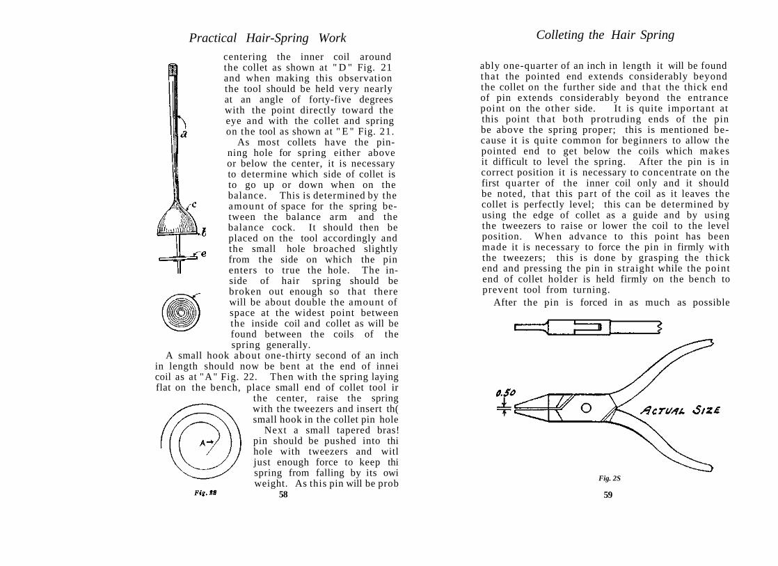
Practical Hair-Spring Work Colleting the Hair Spring
ably one-quarter of an inch in length it will be found that the pointed end extends considerably beyond the collet on the further side and tha t the thick end of pin extends considerably beyond the entrance point on the other side. It is quite important at this point that both protruding ends of the pin be above the spring proper; this is mentioned because it is quite common for beginners to allow the pointed end to get below the coils which makes it difficult to level the spring. After the pin is in correct position it is necessary to concentrate on the first quarter of the inner coil only and it should be noted, that this par t of the coil as it leaves the collet is perfectly level; this can be determined by using the edge of collet as a guide and by using the tweezers to raise or lower the coil to the level position. When advance to this point has been made it is necessary to force the pin in firmly with the tweezers; this is done by grasping the thick end and pressing the pin in straight while the point end of collet holder is held firmly on the bench to prevent tool from turning.
After the pin is forced in as much as possible
Fig. 2S
59
centering the inner coil around the collet as shown at " D " Fig. 21 and when making this observation the tool should be held very nearly at an angle of forty-five degrees with the point directly toward the eye and with the collet and spring on the tool as shown at " E " Fig. 21.
As most collets have the pinning hole for spring either above or below the center, it is necessary to determine which side of collet is to go up or down when on the balance. This is determined by the amount of space for the spring between the balance arm and the balance cock. It should then be placed on the tool accordingly and the small hole broached slightly from the side on which the pin enters to true the hole. The inside of hair spring should be broken out enough so that there will be about double the amount of space at the widest point between the inside coil and collet as will be found between the coils of the spring generally.
A small hook about one-thirty second of an inch in length should now be bent at the end of innei coil as at "A" Fig. 22. Then with the spring laying flat on the bench, place small end of collet tool ir
the center, raise the spring with the tweezers and insert th( small hook in the collet pin hole
Next a small tapered bras! pin should be pushed into thi hole with tweezers and witl just enough force to keep thi spring from falling by its owi weight. As this pin will be prob
58

Practical Hair-Spring Work
without bending, it should be cut off at the thick end about one-thirty-secondth part of an inch from the collet. Then with the flat pliers force it in completely. This is done by placing one end of the pliers against the end of pin, and the other end against the opposite side of collet. This position of the pliers will prevent slipping as the pressure is applied. After the large end of pin has been forced incompletely, the small end protruding through the opposite side of collet can be cut off. The spring will then appear as at "E" Fig. 21.
It is very important that the coil as it leaves the collet be perfectly level before the pin is forced in tight, as otherwise it would be necessary to twist the metal when truing the flat. Some manufacturers use pins that are flattened on one side and in this case the flat side should always be placed against the coil. The flat pliers used in doing this work can be of the ordinary three or three and one-half inch variety, with the ends narrowed down to about two millimeters in width. The inside of jaws should be filed away so that they are separated by about 0.50 millimeter when the pliers are closed. See Fig. 23.
This will prevent damage to the spring in case of possible slipping from the collet when the pin is forced in place. If the leveling of inner coil has received careful attention the entire spring should be quite level after the pin has been flushed.
SO. Correct Form for Inner Coil of Hair Spring
Forming the inner coil of hair spring around the collet is of considerable importance because upon the cleverness with which it is done depends the ease with which the round can be trued. The colleting tool should be held in the left hand with the spring toward the eye so that it will be seen as at "d" Fig. 21 (Page 58).
60
Colleting the Hair Spring
The inner coil consists of three distinct sections, the angle, elbow and spiral. These sections are shown in larger and proper form in Fig. 24. The angle is the straight part of coil immediately attached to collet and its form an angle of about 45 degrees is a continuation of the segment which is held in collet by the pin. See "A," Fig. 24. Theelbow is the curved section next to the angle as per "B" , Fig. 24 and consumes about one-eighth of the coil. All bending of the inner coil in getting it to proper form is centered around the elbow and within the first one-eighth of the coil. The spiral begins immediately beyond the elbow as shown at "C," Fig. 24. which also represents the extreme distance from the collet that any bend should be made
It should be remembered that the entire inner coil, together with the entire spring was originally a perfect spiral and that no part of this spiral has been changed except the small section within the first one-eighth of a coil from the collet and for this reason it is
Fig-t4 not required to go beyond this point in making a correction unless of course the coil has been bent or damaged beyond.
To more clearly define the proper form of the inner coil illustrations 25 and 26 are presented to show how considerably the entire spring can be out
Fig. tS
61

Practical Hair-Spring Work
of center through improper formation of this first one-eighth of the coil adjacent to collet.
Compare these two cuts with Fig. 24 and in the case of Fig. 25 we find considerably more space between the collet and inner coil near the pinning point. See "A" , Fig. 25. In the case of Fig. 26 we find considerably less space. See " B " , Fig. 26.
The three springs as represented by cuts 24, 25 and 26 would be exactly the same in every respect with the exception of the first one-eighth of the inner coil from the point of a t tachment to the collet. Beyond this first one-eighth of the coil each of these springs remains a perfect spiral bu t only in the case of Fig. 24 does the center of the collet represent the practical center of the spring.
Note that in Fig. 25 the entire spring is drawn toward the upper direction while in Fig. 26 it is forced to the opposite direction and the uneven pressure in both of these instances would have considerable effect upon the time keeping of the watches.
It will be necessary in either of these two instances to reform the coil near the point of attachment to collet and make it more nearly agree to the form as shown at "A-B , " Fig. 24.
Very little bending in the proper direction at the center makes a considerable correction as regards the outside coils of the spring.
Reforming the angle and elbow of the inner coil, Fig. 25, so that it will be nearer to the collet, draws tha t entire side of the spring nearer to the collet and forces it away an equal amount on the opposite side, thus doubling the amount of correction actually made. The same thing in reverse applies to reforming the elbo in regard to Fig. 26 so that it will cause the first one-eighth of the coil to be further away from the collet.
In many instances the first coil will begin to run parallel with the second coil directly beyond the point " B , " Fig. 24, although in cases where the space
62
Colleting the Hair Spring
between collet and inner coil is greater this parallel condition will be found to begin at about " C , " Fig. 24.
Particular care should be exercised in colleting a spring to see that it does not receive a very sharp bend immediately at the point of exit from collet similar to that shown at " D , " Fig. 29 (Page 68). -A bend of this description would cause a possible fracture and weakening of the spring at a point where it should be firm.
After the inner coil has been formed approximately correct hold the collet tool in very nearly vertical position with the point upward and observe the flat. If it requires some correction through being too low or too high at any point force it up or down with the tweezers as required and then turn again to the round for any final touch which may be required to complete the colleting.
To level the flat it is best to span the spring with the tweezers point using either point to raise or lower the inner coil at the particular point requiring attention. The beginner may have better success by observing the edge of the collet as a guide for leveling the inner coil but it should be remembered tha t collets are not always of even thickness and therefore the edge cannot always be depended upon as a perfect guide.
63

C H A P T E R X I
T R U I N G HAIR SPRINGS
The value of a properly trued hair spring for a watch that is expected to keep close time is well established among first class adjusters and in producing good work more self reliance is required than in truing balances.
The matter is one entirely dependent upon the eye and hand, as there is no indicator to point out the errors. A proper conception as to where or where not to make bends and training of the eye to determine when a spring is true, in addition to deftness in handling the tweezers is about all tha t the spring truer has to direct him in getting perfect results.
The only tools required are a pair of fine pointed tweezers, a light weight brass calipers and a medium strength glass.
The tweezers should be of fairly good weight to prevent springing apar t at the points but it is necessary that the extreme points come together solidly and that they be finished down fine enough to easily grasp a coil without interfering with the adjoining coils and they should be narrow enough to permit of a bend being made close to the collet when required.
The calipers may be of the ordinary brass variety with stock of about three millimeters in thickness. The jaws of one side should gradually taper to about seventy-five one hundredths of a millimeter in diameter at the ends. About three millimeters of each end should be removed and replaced with hardened steel bearings as shown at " C " , Fig. 27. The ends constructed in above dimensions will be smaller than any collet and a clear view of the inside coil at collet will be provided for.
Each steel bearing should have a hole about 0.25 millimeter in diameter drilled through length-
64
Truing Hair Springs
wise and the hole should be slightly counter sunk on the small end to receive the cones of balance pivots. This will permit the balance to spin on the cones and serve as a protection to the pivots while making bends in truing the spring. It is of course necessary to construct the bearings of a good quality of steel after which they are to be hardened and drawn to a straw color. T h e counter sunk end of the holes should be smoothly finished to prevent marring the cones. Fig. 27 shows calipers with balance and spring in place. " A " representing the f in ished side, " B " the unfinished and " C " the hardened steel bearings.
Fig. £7
51. Inspecting and Truing the Flat
The balance with hair spring staked in place should be placed in calipers and examined, first for t rue in the flat; this is done by slowly spinning the balance while calipers are slanted backward on the bench at an angle of about 45 degrees and looking across the top of spring toward the collet.
It is practical to observe only the inner five or six coils as the weight of the outer coils always causes them to waver considerably even when the spring is true.
The inner coils are supported by the collet and if they are true the entire spring will be true.
The detail to observe closely is as to whether any 65
i

Practical Hair-Spring Work
slight waver or jump exists in the first five or six coils from the center and if it does exist the balance should be stopped and turned slowly back and forth with the finger while the eye determines the exact location of the point of the spring tha t is not level.
Very often it will be found that the inner coil either raises or lowers slightly as it leaves the collet. If it raises, a downward pressure of the tweezers point should be applied to the top of coil near the point of exit. If the coil drops as it leaves the collet the tweezers should be placed under the spring and an upward pressure applied to the inner coil.
In case that the spring is considerably lower just opposite from where it leaves the collet it is best to hold calipers so that spring will be in the horizontal position with the point of exit forward and grasp the inner coil just beyond the elbow with the tweezers held in the vertical position and sway the top of tweezers slightly backward which will raise the side of the spring that is low.
If the spring is considerably high opposite to where it leaves the collet, the top of tweezers should be swayed slightly forward but in either instance the tweezers points should have a firm hold on the coil.
The coil should not be grasped beyond the first one-eighth, however, unless necessary because of previous incorrect bending as it should be kept in mind that fundamentally the spring is level and that the apparent deviation is due entirely to distortion of the extreme end of the inner coil where it is pinned to the collet. In every instance the above stated operations are to be made with the left hand steadying the calipers while the right hand manipulates the tweezers.
If the spring wobbles considerably because wrong bends have been made it should be removed from the balance and placed on the colleting tool where better progress can be made after which it can be more easily trued in the calipers. As all springs on
66
Truing Hair Springs
fine watches have overcoils, it will be especially important that only the inner five or six coils be observed as previously stated. Training the eye to ignore the wavering of the overcoil and outside coils is one of the points in which perfection is to be attained before spring truing becomes a really simple matter.
52. Inspecting and Truing the Round
For observation and making bends in truing the round it is advisable that the top of calipers be leaning slightly toward the operator as this position will make it possible to observe the top of the coils. Best results in observation or making bends are not always obtained in looking directly down upon the coils and sometimes a slight angle is best.
If the center coil has been formed on colleting tool as per Fig. 24 (Page 61), it will not be difficult to get the round true.
*If the round is perfectly true and the balance is spinning slowly in the direction so that the coils envelop they will appear to be whirling into a hole of which the collet is the center.
*When the balance is spinning in the opposite direction so tha t the coil will develop from the point of a t tachment at collet; then the appearance will be similar to the waves formed by dropping a stone in still water.
The above appearance in both instances is due to the fact that the inner coil is properly centered and the eye follows the perfect spiral form of the coils to and from the center according to the direction in which the balance is turning.
As in truing the flat, only the inner five or six coils should be observed and if any jump or hesitation is noted the balance should be stopped and then turned very slowly with the finger while the inner coil is carefully examined. If the collet is true it can be of considerable benefit in the examination.
67

Practical Hair-Spring Work
As stated and illustrated in section 50 (Page 61) the coil should leave the collet at an angle of about 45 degrees which represents a straight continuation of its form within the pin hole and this form should be distinct up to where the elbow begins. Beyond the elbow the coil should begin to assume the spiral form which will cause it to gradually increase its distance until the greatest space between the collet and the inner coil will be just before it begins to take its place as the second coil.
Fig. 28 shows the development of the inner coil to the left as it will appear in the calipers, when attached to the balance, in the case of most American watches. In the case of most foreign watches the development would be just opposite or to the right similar to Fig 24 (Page 61).
In some instances the repairer will find hair springs that have a very sharp bend at the point of exit from the collet as shown at " D " , Fig. 29.
If the spring is t rue in these cases the form of the first one-eighth of the coil will be as shown
i f r o m " D " t o " E , " Fig. 29. I t i s quite possible for a bend of this description to cause a fracture of the coil at collet and while such bends should not be made in the original fitting of the spring
it is hardly advisable to rebend them to proper form as any additional bending may break the spring off entirely.
Figures 30 and 31 showing the spring in reverse development as compared to Figures 25 and 26 (Page 61), demonstrate approximately the most usual condition of the inner coil of a hair spring when the round truing has been mishandled.
The solid lines represent the coil in an incorrect 68
Truing Hair Springs
position and the broken lines have been applied to show where the solid line should be in comparison with the circumference of the collet.
The object in this demonstration is to show how and where to make the few bends required in the solid line so tha t it will assume the position of the broken line, and to supply a workable means of s tudy showing tha t when this is done to the inner coil of a spring it will be centered, or what is called t rue in the round.
In accomplishing this fact it is not necessary to make any bend beyond one-eighth of the coil from the point of a t tachment to the collet.
The first bend in the case of Fig. 30 would be to shorten the angle or straight par t at "A" . T h e tweezers points should grip the coil at "A" and the tweezers should then be rolled toward the left (not sharply twisted) until curve assumes the form " A " to " B " of the broken line. It will then be necessary to grip the coil at " B " and make a slight squeeze bend to the right or away from the collet to modify the sharp curve.
If it is necessary to make another bend to get the entire coil over the broken line it will probably consist of an outward bend at "C " No bending is required beyond the arrow " C " and these three bends properly made are all tha t will be required to get the spring true in the round.
In the case of Fig. 3 1 a little more care is required in making the first bend of the solid line to cause it to assume the position of the broken line " D " to " E " so tha t the coil will not be broken off at the collet.

Practical Hair-Spring Work
The tweezers points should grasp the coil a t " D " and squeeze it slightly toward the right to remove the sharp bend. This will force the solid line out too far beyond " E " and " F " and it will be necessary to grasp the coil at " E " and make a rolling bend to the left and if this does not give it the correct form another bend at " F " should place the entire coil in correct position. In making any of the above bends it is necessary that the spring be held firmly on the colleting tool or in the truing calipers.
Any bends that might be made beyond the first one-eighth of the coil would simply make it more difficult to get the coil in correct position.
Bends described should be executed more in the manner of a kneading operation rather than in the manner of making a sharp twist.
A little study of Figures 30 and 31 and comparison with actual springs on the balance or on the colleting tool will soon develop a clear understanding as to how and where to make bends in order to obtain a perfectly true spring in the round.
The feature of spinning the balance slowly in the calipers and observing the coils should always be the final test for true and continued training of the eye will eventually make it possible to detect and eliminate the small errors that enable one to attain perfection in both flat and round truing.
It is important to again call attention to the fact tha t only the inner five or six coils should be observed when spinning the balance and making the examination in either round or flat as the overcoil and stud will confuse for some little time until concentration on these center coils becomes a settled fact.
It is often advisable for beginners to have a perfectly true spring staked to a balance for the purpose of comparison, as slight variations from true may at times be difficult to detect and by occasionally observing the smooth, even movement of a true spring, a new inspiration will arise to
70
Truing Hair Springs
assist in locating the proper point at which to make the bend. Incidentally should the spring be true and possibly in doubt, then a comparison with the true spring will assist in reaching an immediate decision without unnecessarily bending it.
In truing springs it is advisable to eventually train the eye to observe the round and flat without considering the edges of collet as a guide. All expert spring truers follow this rule because of the uncertainty associated with the perfect round and thickness of collets. It is also possible to do the work more quickly. Beginners however often find considerable advantage in using the collet as a guide until fair progress has been made.
71

C H A P T E R XII
VIBRATING OR TIMING HAIR SPRINGS
53. Some Factory Methods of Vibrating
After the operations of selecting, colleting and truing a new spring have been completed, the next operation will be that of vibrating or timing the spring to the balance.
This consists of finding the proper length of the spring to cause the balance to make a certain number of vibrations in a given time. Usually this is referred to as a certain number of beats per hour, each beat denoting the drop of an escape wheel tooth on a pallet stone. It is clear that vibrating deals with timing while selecting deals entirely in the volume or size of the spring.
The old-time watches, generally known as slow train watches were constructed to make either 14,400 or 16,200 beats per hour. All modern watches are known as quick train and produce 18,000 beats per hour.
In the factories machines made on the watch movement plan sometimes with the train in a straight line are generally used, a large seconds dial is fitted around the fourth pivot which carries a long second hand. The balance jewels and fork slot are made large enough so that all balances of a certain model will enter and can be run upon being placed in position. A pair of finger clamps are supplied for grasping the outside coil while the balance is running and upon opening these clamps the coil can be shifted either forward or backward for causing the balance to run either slower or faster. Comparison of time is made either with another movement or with a ticker service connected with a master clock, which by means of a common telegraph instrument sounds the seconds regularly. Several machines can be run by one operator at a
72
Vibrating Hair Springs
time and if upon running five minutes the time is found to be two seconds slow the spring is shortened in the clamps about one-fourth of an inch, if the time is fast the spring is lengthened and another test for time is made. This method is used most frequently for cheaper grades of watches upon which certain pinning points are not observed.
Another method of factory vibrat ing for high-grade watches is to have three separate machines, one of which is fitted with a s tandard balance, another with a s tandard spring and a third machine which is used for proving the time. All hair springs of a certain model watch are colleted, overcoiled and studded after which they are placed on the s tandard balance of the one machine and timed for a certain number of minutes. After this timing the springs are placed in a receptacle which is numbered to correspond with the seconds fast or slow on the s tandard balance.
All balances of this particular model are placed on the standard spring of the proper machine and timed for an equal number of minutes after which they are separated and given certain numbers. These numbers are so arranged tha t they will correspond with each other; for instance a spring tha t has shown a gaining rate of several seconds in the test will be placed with a balance showing a certain losing rate . After the springs are staked to the balances they are tested in the third machine which will note any remaining error, for which correction is made by means of changing the weight of the balance screws.
This method permits of making the springs all of equal length and of pinning the collet and stud points in certain relation to each other, which is of very great importance in temperature and fine position adjusting and which is thoroughly explained in the author 's book "Rules and Practice for Adjusting Watches ."
In the production of the cheaper grades of watches 73

Practical Hair-Spring Work
the relation of the points of a t tachment of the spring at collet and stud are not observed. The springs are merely vibrated to the balance regardless as to actual length and together with the labor saved in less rigid inspection the manufacturer is enabled to reduce the cost of balance and hairspring work about eighty per cent.
This method is of course to be followed in replacing springs of cheap watches in the repair shop as explained in sections No. 54 and 55 following.
54. Methods of Repair Shop Vibrating
Several methods of vibrating are open to the repairer. A standard vibrator of very simple construction as shown in Fig. 32 can be produced by any workman.
An old dial plate or similar piece of metal as shown at "f", with an old enamel dial or flat piece of glass with white paper underneath as shown at " g " can be fastened to the plate. A metal pipe about five millimeters in diameter and about three times as long with a two millimeter hole, should be set upright at about where the seconds hand hole is located in the dial, as at "h." This pipe should have a hole drilled horizontally through to the center, about two millimeters from the top, threaded and fitted with a thumbscrew as shown at " i . "
Fig. St
74
Vibrating Hair Springs
Then secure a piece of brass or nickel wire about three centimeters long and small enough in diameter so that it will fit freely in the pipe and at about one centimeter from one end bend this wire at right angles as shown at " j . " This par t is to be used for the purpose of raising or lowering the wire and to be held in any position by the thumbscrew.
When in place the long part of the wire will be in a horizontal position. About three millimeters from the other end bend it downward so tha t it will parallel the section in the pipe. Drill a hole in this end just large enough to receive a hairspring stud and then fit a small screw near enough to the end to hold the stud in position as shown at "k . " All tha t is required to complete the vibrator is a balance and spring properly timed to be used as a s tandard. Place the stud in position and adjust the bar in the pipe so that the lower balance pivot just rests on the dial or glass, swing the bar slightly to one side of center and set the thumb screw up tight.
The spring to be vibrated to time should be staked to its balance and with the tweezers in the right hand grasp the outer coil at some point and raise it until the balance is suspended from the bench. Then with the fingers of the left hand, turn the balance around one-half way or more and release it. The balance will then begin to oscillate and should be lowered until the lower pivot just rests on the dial similar to the standard balance as shown in the cut Fig. 32.
T h e balance will now swing forward and backward just as it does in the watch. It should be moved toward the standard balance until the ends of the screw-heads strike the screws of standard balance just hard enough to set it in motion. Then quickly withdraw the balance which is held with the tweezers until the two balances are two or three millimeters apart . Next observe the speed at which both balances are mov-
75

Practical Hair-Spring Work
ing either by comparison of the screws or balance arms and if correct the balance attached to the spring to be vibrated will move in exactly the same time that the standard balance does. A little practice will soon accustom the eye to note the difference in the speed of the two balances as well as to when they are moving in equal time.
If the balance is moving slower than the standard it is necessary to shorten the spring and if it moves faster the spring should be lengthened. This is accomplished by moving the tweezers either away from or toward the end of the coil. For this purpose it is best to use two tweezers, one in the left hand for supporting the spring while the tweezers in the right hand grip the coil at the proposed new vibrating point.
When it is noted tha t the screws or arms of both balances are maintaining the same speed for a period of thirty or forty seconds then a bend can be made in the coil at the point held by the tweezers and this will represent the proper location for the stud. About one-eighth of an inch of the coil beyond the stud point may be allowed to remain for possible future alteration and all of the outside coil beyond this should be broken off. As all modern watches have 18,000 beats per hour, three balances with springs timed to this number of beats should be supplied as standards, one large and one medium and one very small size for miniature watches as it is not practical to compare the oscillations of a 5 Ligne balance with those of an eighteen size.
Balances that have springs timed to 14,400 and 16,200 beats can also be supplied, for use on old model watches, bu t as there are very few of such watches in existence they will seldom be required and the vibrating can be done by pulling the coil through the stud to correct timing.
76
Vibrating Hair Springs
55. Counting the Vibrations
One method tha t is very often used by skilled repair workmen, is tha t of counting the vibrations.
This is _ accomplished by placing any pocket watch having a second hand on the bench, with the dial up, and allowing the balance to oscillate with the lower pivot resting on the watch glass. T h e outer coil is held by the tweezer and comparison of the oscillations is made with the second hand.
If the spring is to be vibrated to 18,000 beats per hour, it will equal three hundred beats per minute or one hundred and fifty beats per one half minute.
It is impossible to count three hundred in one minute and it is also impossible for the eye to follow each oscillation accurately; therefore every other oscillation is counted. This makes it less difficult, as one of the balance arms can be followed, and counted, each time tha t it arrives at its full arc on one side and instead of counting three hundred per minute it is necessary to count only one hundred and fifty per minute or seventy-five per one-half minute. It is very important tha t the second hand be observed accurately when the counting is started and when it is finished, and when a correct count of one hundred and fifty arcs have been made in one minute, it will be necessary to simply multiply this by two, which equals the three hundred beats per minute.
If the second hand is not accurately observed and if the count is inaccurate the vibrating point will be considerably out of the way.
For example we will assume that there is an error in the count of one arc amounting to two beats in one minute.
This will make a difference of one hundred and twenty beats per hour when multiplied by sixty.
One hundred and twenty beats per hour multiplied by twenty-four hours equals 2880 beats and
77

Practical Hair-Spring Work
this divided by 300 places the error for twenty-four hours at 9.6 minutes.
It is good practice to count the arcs of a balance and spring that have been timed in a watch by holding the stud with the tweezer and allowing the balance to oscillate on the watch glass. After the arcs can be correctly counted and repeated several times for one minute and one half minute periods, some idea as to the value of this method will be obtained. When a new spring is being fitted or when the vibrating point is totally unknown it is necessary to find the approximate point by counting for five or ten seconds at a time and shifting the point held by the tweezers either forward or backward on the coil until the correct count for one minute is obtained.
The writer's personal recommendation to the repairer would be to adopt the method of using the vibrator with several different sizes of balances as this has proved to be the most satisfactory method in his own experience as well as tha t of many others.
In selecting balances and springs for use as standards it is best to prove that they are properly timed by actual tests in watches tha t are properly equipped with regulator pins. It is necessary to consider the pins and that they be adjusted close to the coil so tha t the standards will be timed as nearly correct as possible.
Slight allowance can be made in vibrating new springs when it is observed that the regulator pins are farther away or nearer to the stud than that at which the standard was timed.
78
CHAPTER XIII
OVERCOILING HAIR SPRINGS
56. The Gradually Inclined Bend for Raising the Overcoil
Producing overcoils or new springs or altering the height and correcting the curves of an overcoil are simple matters for the springer of experience, though it requires considerable practice to become expert at the work.
Figure 33 demonstrates the gradually inclined overcoil which is probably the most simple method of raising the coil. "A" represents the first bend and " B " the second bend, while "A", " B " , C" represent the entire overcoil. This method generally consumes about one-fourth of the outer coil in rising before it begins to curve over the spring.
Pig. SS
The tools required for the gradual incline style of overcoil consist of two tweezers with well fitting points for raising the coil and several sizes of overcoil forming tweezers for various sizes of springs. For convenience in making the bends the spring may be staked on the balance which should then be placed on a block having a hole large enough to admit the rollers.
The first bend is made at about three-quarters of a coil from the end as designated by "A" Fig. 33 and the coil should be firmly grasped at the point designated with one of the tweezers held in the left hand and in a vertical position. Then with the second tweezers held in the right hand grasp the coil about one millimeter to the right of the first tweezers, — both tweezers in the vertical position.

Practical Hair-Spring Work
Now hold the left hand tweezers steady and bend the top of right hand tweezers back toward yourself sharply until the coil is raised to a point just opposite as designated by " B " Fig. 33.
*While making this bend it is very essential that the tweezers in left hand be held rigidly upright or possibly swayed slightly forward while the top of right hand tweezers is swayed sharply toward yourself. T ry this on a few old springs.
When the bend is properly made the high point of the coil will be just opposite as at " B " Fig. 33 and from that point the coil will decline out to the end so that it will be parallel to "B"-"A" .
Next with balance in the same position on the block grasp the coil at the high point " B " with the tweezers in the right hand and then with the tweezers in the left hand grasp it about one millimeter to the left of right hand tweezers and sway top of left hand tweezers away from yourself sharply until the end of the coil " C " is raised to a level with " B . "
These two bends are all that is required for rais-ng the coil, though at first several trials will be required before the desired results are obtained. In making duplicate bends because of lack of results the first time it should be carefully noted that the tweezers grasp the coil at exactly the same places to avoid kinking the coil.
It should also be remembered that it requires much more time to explain the operations of the several bends than it requires to actually make them for the entire time required for raising an overcoil consists of only a fraction of a minute.
The instructions regarding the particular hand in which the tweezers are held either rigid or to be swayed one way or the other in making the bends are for springs developing to the left from the collet as most American springs do, and for springs that develop to the right it is necessary tha t the holding
i m p o r t a n t note. — 80
Overcoiling Hair Springs
and swaying be done by the tweezers in ' the hands jus t in reverse to these instructions.
If the raising of outside coil has been properly executed, it will describe the same circle as it did previous to being raised, namely, parallel to the second coil, only higher.
It will then be ready for forming the curves and for this work the overcoil forming tweezers as shown in Fig. 34 is used.
This style of tweezers is very necessary for coiling and in place of being pointed, the ends are made in various widths for the different sizes of springs. The inside of one end is concave, while the opposite is convex and they fit closely together when the tweezers are closed.
The first bend to be made with this tweezers is the main or elbow bend as shown at " A , " Fig. 35 and it should be made a trifle over one-half way across from the vibrating or stud point as represented by " B , " Fig. 35. The broken line represents the proportion of the outer coil that is used in forming the overcoil. Close attention to this detail will give assurance as to the proper location of the elbow after the overcoil has been completely formed. The coil should be at least the width of the coils above the body of the spring at the elbow to provide sufficient clearance though this clearance may be considerably greater in larger watches depending upon the available spring space.
The elbow bend "A", Fig. 35, together with the other curves of the overcoil can best be made by placing the balance and spring in the hair-spring truing calipers as shown in Fig. 27 (Page 65), then place the convex end of tweezers on the inside of
81
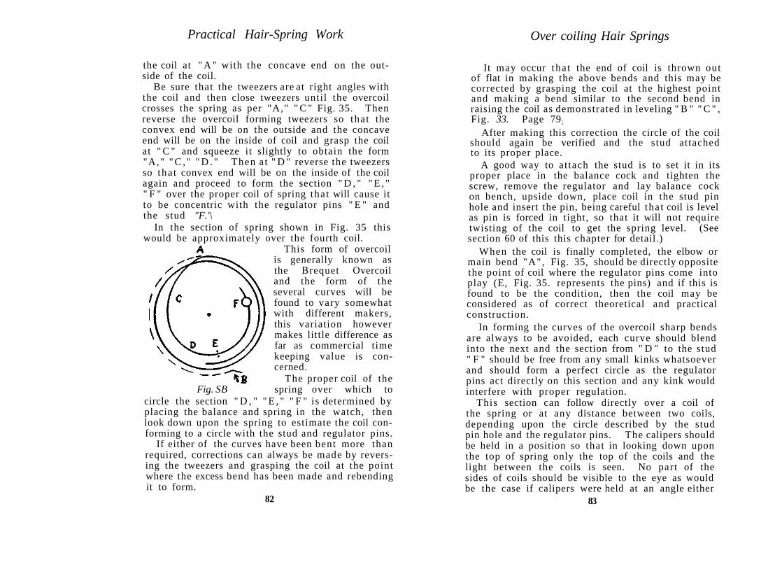
Practical Hair-Spring Work
the coil at " A " with the concave end on the outside of the coil.
Be sure that the tweezers are at right angles with the coil and then close tweezers until the overcoil crosses the spring as per "A," " C " Fig. 35. Then reverse the overcoil forming tweezers so that the convex end will be on the outside and the concave end will be on the inside of coil and grasp the coil at " C " and squeeze it slightly to obtain the form "A," " C , " " D . " Then a t " D " reverse the tweezers so tha t convex end will be on the inside of the coil again and proceed to form the section " D , " " E , " " F " over the proper coil of spring tha t will cause it to be concentric with the regulator pins " E " and the stud "F.'\
In the section of spring shown in Fig. 35 this would be approximately over the fourth coil.
This form of overcoil is generally known as the Brequet Overcoil and the form of the several curves will be found to vary somewhat with different makers, this variation however makes little difference as far as commercial time keeping value is concerned.
The proper coil of the Fig. SB spring over which to
circle the section " D , " " E , " " F " is determined by placing the balance and spring in the watch, then look down upon the spring to estimate the coil conforming to a circle with the stud and regulator pins.
If either of the curves have been bent more than required, corrections can always be made by reversing the tweezers and grasping the coil at the point where the excess bend has been made and rebending it to form.
82
Over coiling Hair Springs
It may occur tha t the end of coil is thrown out of flat in making the above bends and this may be corrected by grasping the coil at the highest point and making a bend similar to the second bend in raising the coil as demonstrated in leveling " B " " C " , Fig. 33. Page 79;
After making this correction the circle of the coil should again be verified and the stud attached to its proper place.
A good way to at tach the stud is to set it in its proper place in the balance cock and tighten the screw, remove the regulator and lay balance cock on bench, upside down, place coil in the stud pin hole and insert the pin, being careful tha t coil is level as pin is forced in tight, so that it will not require twisting of the coil to get the spring level. (See section 60 of this this chapter for detail.)
When the coil is finally completed, the elbow or main bend "A", Fig. 35, should be directly opposite the point of coil where the regulator pins come into play (E, Fig. 35. represents the pins) and if this is found to be the condition, then the coil may be considered as of correct theoretical and practical construction.
In forming the curves of the overcoil sharp bends are always to be avoided, each curve should blend into the next and the section from " D " to the stud " F " should be free from any small kinks whatsoever and should form a perfect circle as the regulator pins act directly on this section and any kink would interfere with proper regulation.
This section can follow directly over a coil of the spring or at any distance between two coils, depending upon the circle described by the stud pin hole and the regulator pins. The calipers should be held in a position so that in looking down upon the top of spring only the top of the coils and the light between the coils is seen. No part of the sides of coils should be visible to the eye as would be the case if calipers were held at an angle either
83

Practical Hair-Spring Work
too great or too small; this will insure an approximate circle within the range of the regulator pins which could not be obtained without proper guidance of the under coils even though they are spiral in form.
When examining the level of overcoil after the stud has been attached it may be noticed that the end hangs somewhat nearer to the spring than the center of the coil, this is due to the weight of stud and unless it is plainly noticeable that the coil has been bent downward there should be no alteration attempted before placing the balance in the watch for verification.
57. Short-Angle Bend for Raising the Overcoil and Description of Tools.
The short-angle bend is used very extensively at the present time in raising the overcoil of hair springs. It consumes only about one-eighth of the coil from the point of rising to the point where the coil assumes its proper level above the spring.
When properly executed this method admits of a very fine development of the coils as they wind and unwind during the oscillations of the balance. Such springs are more easily circled in the watch and because of the sturdiness of the bends they will retain their form at this point much longer than will the gradually inclined coil which is more easily pulled out of its position through rough handling.
There are several methods of forming this bend. Perhaps the most practical is the method used generally by the Swiss.
This requires a special tool in the form of tweezers fitted with steel or ivory ends the latter being intended to prevent scratching the finish of the coil in the slightest degree.
The tweezers having steel ends can be obtained ready made and are shown in Fig. 36.
84
Overcoiling Hair Springs
Fig. 86
The width of the slot in this tool is regulated by the slide and small set screw as shown in the above cut.
For the information of those desiring to devote the time to making a tool with ivory ends the following details together with Fig. 37 which is shown in twice the regular size for sixteen size springs will be of considerable assistance although the steel tweezers as described and shown in Fig. 36 are very satisfactory in doing the work.
First obtain a large sized extra heavy tweezers as per " 1 " Fig. 37 and cut off the points to where they will be about three millimeters in width. Then form a piece of ivory, tapering to the width and general form of the ends of tweezers and about six millimeters long by about three millimeters in thickness.
Cut or file this to about one millimeter in thickness for a distance of four millimeters from the wide or rear end and allow the forward part to remain full thickness, fit this into the tweezers as shown at "m," Fig. 37, and supply a small screw as shown at "n" to hold it tight.
The forward part which has been left at full thickness of three millimeters should be filed to a concave form about one millimeter in depth at the center as shown at "O" of the end view. About one-fourth of a millimeter from the edges this section should be flat as shown at "P . " This completes one side of the ivory ends and to the opposite inner side a smaller section of ivory should be attached in the same manner; the forward end need be only about two millimeters in thickness and this should be finished to a convex form, retaining the
85

Practical Hair-Spring Work
Fig. S7
full two millimeters in thickness at the center " q " Fig. 37.
This end should fit closely into the concave section of the opposite end. About one-half millimeter from the extreme end it should have a fine slot about one-tenth of a millimeter in width and about three-tenths of a millimeter in depth as shown at "r ."
This slot should be cut crosswise of the convex end and parallel to the end. The depth of slot should be the same from one side to the other as far as it enters the concave section of the opposite ivory end and it is one of the most difficult and important parts of the tool to properly construct.
A large stop or set screw should be applied to the end having the concave section as shown at " S " , and a small block of steel should be fastened to the opposite side. This is for the purpose of adjusting the two ends to prevent them from coming solidly together when the tweezers are closed, for it is necessary that the concave and convex surfaces be separated by about fifteen one-hundredths of a millimeter for large springs and the set screw allows for regulation of this space. A tool of smaller proportions is necessary for smaller springs.
The first bend should be made a trifle less than three-quarters of a coil from the end of spring. Place the overcoil forming tweezers on the bench with the slotted side facing upward as shown in
86
Overcoiling Hair Springs
Fig. 37 and with end of tweezers pointing toward yourself. Next place the outer coil of spring in the slot at the point stated above. At this time the spring is to be in the reverse position compared to that which it will occupy in the watch. The coil should be held level in the slot of tweezers so that the bend will be made properly; then press the upper side of tweezers down firmly until the set screw prevents further action and the first bend " A " to " B " Fig. 38 will have been made and the coil will have the appearance as per " A " - " B " with the extreme end parallel to it. For the second
bend reverse the spring and place raised part of coil in the slot so that the bend previously made at " A " will be about one-eighth of an inch to the right of the tweezers, hold the coil level and again press the upper part of tweezers down firmly to the stop screw and the second bend will have been completed. This produces the two main bends that raise the outer coil and completes the work that this tool can be used for. It may be noted that from the second bend to the end of the coil it will drop sharply toward the spring so that the extreme end may be touching the main coils.
In order to raise the end so that the entire coil will be level, one additional bend is all that will be required to obtain correct form as shown in Fig. 39 where "A" represents the first bend and " B " the
87

Practical Hair-Spring Work
second with " C " representing the extreme end of the coil.
The details of making the third bend which levels the coil are similar to those used in making the second bend of the gradually inclined coil as two tweezers are used in making the correction.
Assuming that the spring develops to the left as is the case with most American watches; grasp the coil about one millimeter to the left of the second bend " B " Fig. 39 with the tweezers held perfectly upright in the left hand.
Then with a second tweezers in the right hand and held perfectly upright grasp the coil a trifle to the right of the bend " B " and sway the top of the right hand tweezers sharply toward yourself until the section of the coil " B " - " C " assumes the perfect parallel position above the spring just as it appears complete in Fig. 39.
While making this bend it is important that the left hand tweezers be held rigid and if the bend has been correctly made the overcoil will be level and just as much above the rest of the spring as the extent of elevation between the first and second bends.
For Swiss or other watches tha t have springs developing to the right from the collet, the two bends made by the overcoil raising tweezers require tha t the spring be in the opposite positions, but the tweezers should retain the same position on the bench.
After the coil has been leveled it will be ready for circling and the regular overcoil forming tweezers, Fig. 34 (Page 81), together with the instructions on pages 81 and 82 are used for this purpose. In either instance there may be variations in circling the coil depending upon the style of coil desired and after due practice and examination of the springs of fine watches it will be easy enough for
88
Overcoiling Hair Springs
the workman to duplicate any kind of bends tha t may be desired.
58. Relationship of the Points of Attachment of the Spring to Collet and Stud
In the adjustment of high-grade watches certain pinning points, or the relation of the point attached to the collet and the point attached to the stud are observed.
Manufacturers obtain such relationships by breaking off the outside coil at a certain place, so that when the overcoil is formed the stud can be placed at the desired relation and the length of the spring is never altered thereafter in the operation of vibrating. All corrections in time are made by altering the weight of the balance by means of screws that are either heavier or lighter as required.
In fitting odd springs however it is necessary tha t the relative position of the points of at tachment be obtained almost entirely through alterations of the spring, as this will cause less disturbance of the temperature adjustment than would be caused by any considerable alteration of the weight of balance after it has passed through the original temperature adjustment.
When it is understood that there is to be a definite relationship between the collet and stud points of at tachment of a new spring, there will be no difficulty in obtaining the desired result if a few important points are observed. First the spring should be broken out rather close around the collet and secondly when the location of the stud is determined through vibrating only a very slight bend should be made in the coil for the purpose of noting its location, and a quarter of the outside coil should be allowed to remain beyond the vibrating point.
A comparison of the two points of a t tachment should then be made. If, for instance, it is desired
89

Practical Hair-Spring Work
tha t the completeJ spring be of exactly even coils it will be necessary thai the bend made ir,.outer^ coil be located just about one-quarter of the outeide coil short of even coils. Should it be found to be so, we will have been fortunate, for when _ he oyer coil is raised and circled, the stud point will be just about even with the collet point of at tachment
It will be quite probable however that it will not be so and for example, we will assume that the bend in outer coil is just even or slightly beyond he even coil point before the over cod is raised. T h « wouia cause the spring to be a quarter of a coil,or-more longer than even coils after the overcoi has been raised and circled. T h e proper alteration t c . b e made would be to replace the spring on the collet holder and remove it by pushing out"the= pin with_a fine pointed punch, then break off about one-third of the inner coil and recollet. The stud point of location on the outer coil, should then be moved forward, just the same distance, as the length ot the small piece of spring broken off at the center
This will cause the vibrating of the spring to remain correct and also cause the spring to be 01 even coils after the overcoil has been raised and circled All surplus p a r t of the coil extending beyond the stud point of location may be broken away before the overcoil is raised. A little thought on the subject and a few experiments will soon make it an easy matter to ob ta in desired relationships ot the two points in the fitting of new springs. m
In case that it is sometimes found, that it will be necessary to break away too much at the center, it will be best to select another spring about one-half number weaker or stronger. This w i n e a r l y always be effective as all good quality springs are carefully gauged by t h e makers. Diagrams ^ j th theoretical and pract ical descriptions of p m n n g points will be found in the author s^book Rules and Practice for Adjusting Watches.
90
Attaching the Hair-Spring Stud
59. Attaching the Hair-Spring Stud
In the factories where only a few different sizes of Hair-Spring Studs are used we will find special tools for holding the stud firmly while the outer end of the spring is being securely attached by means of forcing the small brass pin in place. The operatives who do this work may attach hundreds of studs per day and necessarily have proper equipment to get the most out of their efforts. The tool holding the stud generally has a small lever which is operated with one of the fingers in opening and closing the jaws.
High grade cutting pliers with narrow points and sharp cutting edges are used for removing the surplus ends of the brass pins after they have been forced in place by the tweezers and small flat pliers. The pliers and tweezers are constantly kept in good condition to prevent marring the spring through slipping.
In the repair shop nearly every hair-spring stud is different because of the fact tha t many makes and sizes of watches are handled daily. The best method probably for this class of work is to remove the regulator from the balance cock, attach stud in proper place securely held by the screw, tu rn balance cock upside down on the bench, and remove pin from hole by means of a pointed instrument if required. The pressure with the point should be applied from the same side of stud hole on which the end of spring enters as all stud pins are applied from the opposite side of hole to which the coil enters.
At this point we are ready to repin the stud. First insert a pivot broach in the stud hole (from the opposite side to that which the coil enters) to clean out any remaining burrs or brass, then insert end of spring keeping it in proper place and level while the tapered brass pin is carefully applied with the tweezers from the opposite side.
91

Practical Hair-Spring Work
After this has been done use the fine cutting pliers to cut off the thick end of pin about one sixteenth of an inch from the hole, then force pin in tight with the small flat pliers used in colleting, resting one jaw against the thick end of pin and the other jaw on opposite side of the stud. This should cause the spring to be firmly attached to the stud as well as to be almost perfectly level and the next operation is to remove the surplus pointed end of the pin quite close to the stud with the cutting pliers. If the stud is not perfectly level with the coil it will be necessary to grasp the coil near the stud with good tweezers and level it before removing the stud from balance cock.
60. Centering the Hair Spring on the Balance Cock
After the stud has been attached to the hair spring as per previous section it becomes a simple matter to determine as to whether the spring is centered or not.
If the entire overcoil is properly formed, the center of the collet will be directly in line with the hole in balance jewel when the spring is attached to the balance cock and detached from the balance.
Turn to Fig. 35 (Page 82). The black dot in the center represents the hole in balance cock jewel and if the section of the coil "D" to " F " is formed over the proper coil of spring and the section "A," "C," " D " is properly formed then the center of collet hole will be directly in line with the hole in the jewel.
When the balance cock is held horizontally and the center of the collet hole is toward " E " as compared to lining up with the jewel hole — then the overcoil is formed one or more coils too far inward.
On the other hand, if the center of the collet hole is toward the elbow "A" as compared to lining up with the jewel hole — then the overcoil is formed one or more coils too far out.
92
Centering the Hair Spring
As a method of correction the rule would be to remove the spring from the cock, place it on the colleting tool and then the first and most effective bend to make is to grasp the overcoil about one-half way between " C " and " D " with the overcoil forming tweezers and bend the coil — out or in — as required and then recircle the coil from " D " to " F " over the proper coil of the spring and test again on the balance cock.
By means of the above method a very good approximate centering of the spring can be obtained. The final proof however as to the concentricity of the spring is obtained after the balance and spring have been placed in the watch as it is quite possible that there may be other points of the overcoil that require slight touching up in addition to those mentioned above.
Any slight bends that are made in the overcoil after it is in the watch should be made with a fine pointed tweezers that are used only for truing the spring and for slight corrections of the overcoil. Before applying the tweezers to the coil it should be carefully noted that the bend to be made will shift the body of the spring in the direction desired as an incorrect bend may cause much unnecessary work before the spring is again centered as good as it was.
When the spring is properly centered the section of the overcoil " D " to " F " Fig. 35 will be concentric with the regulator pins "E."
As the balance oscillates the coils of spring will wind and unwind evenly at all points. For close observation the balance should be stopped and the coils will be found to be either wound up and close together or they will be unwound and farther apart than normal. As the balance is allowed to swing one-half way around and again stopped the opposite effect will prevail and the eye can easily observe as to whether the space between the outside coils in either case is the same all around the spring. This is a good test for good work on high-grade watches and it is well worth much consideration and practice.

Practical Hair-Spring Work
61. Fitting a Hair Spring Supplied by the Manu
facturer of the Watch
One of the most usual methods of replacing a hair spring is to obtain a spring for the particular model of watch as supplied by the manufacturer of the watch.
Springs of this description can generally be obtained from material houses completely over-coiled, studded and colleted for many different models of watches.
It is often presumed that because the spring is catalogued and designated for a specific model it will merely require staking to the balance to perfectly replace the old spring in time keeping. Should this not be a fact however there is a possibility of disappointment on the par t of the watchmaker.
There are several reasons as to why a spring designated for a particular model of watch by the manufacturer may be very far from perfect in time keeping results and this may happen without any laxity on the pa r t of the manufacturer as he may do his very best to supply the correct spring and does supply the correct spring as far as human effort will enable him to do so.
In fact he supplies the same spring tha t is supplied to the vibrators in his own hair-spring department and the workers in this department seldom find that a spring applied to a balance will time correctly until specific alterations have been made. These alterations are incidentally not always made by changing the weight of the balance as frequently the variation is so great that it is necessary to try a different strength spring entirely.
Springs of the same lot will show some variation and balances of the same lot tha t appear to be exactly the same will vary in time keeping and the only way to obtain a correction is through a knowl-
94
Fitting a Factory Hair Spring
edge of the practical details as explained in Chapter X I I of this book.
The strength of a hair spring may be quite accurately assumed by means of the fine strength testing gauges which all hair-spring manufacturers use.
The weight of a balance can also be accurately estimated but there is no way through this testing and weighing by which the two may be assembled and correct timing results assured.
The cause for this is the fact that there is no connection between the total weight and the timing weight of a balance wheel.
This is explained by the fact tha t the mat ter depends entirely upon the distribution of the weight of the balance and not upon its net weight.
For instance two balances may in general appearance and in wreight appear to be exactly the same bu t one may have a slightly heavier arm and a slightly thinner rim while the other m a y b e jus t in reverse.
A spring fitted to the balance with the heavier arm and lighter rim and timed perfectly will lose considerable time if it is transferred to the balance of the same weight but having a lighter arm and heavier rim. This is based on the simple rule covering the fact that a losing or gaining ra te is obtained by moving the weights farther from or nearer to the center and it applies to the transfer of the weight of the various permanent parts of the balance in exactly the same way that turning a pair of time screws outward or away from the center will cause a losing rate and turning them inward toward the center will cause a gaining ra te while the total weight of the balance will remain the same in either instance.
The fact then tha t springs supplied by the manufacturer do not always time perfectly is not to be considered unusual because the manufacturer himself would be obliged to bring the spring and bal-
95

Practical Hair-Spring Work
ance to time before the combination would be ready for the watch. It is obvious then that it would be necessary for the manufacturer to have the balance in every case where a new spring is to be fitted if correct timing is expected.
Approximately close results may be obtained in most instances by ordering a spring as catalogued for a particular model of watch. The accuracy in timing however cannot be expected to be as good in many instances as would be the case if the balance wheel complete were sent to the manufacturer to have the spring fitted.
The manufacturer having a large selection of springs will overcome the greater variations by selecting a spring that will vibrate the balance to time and will change the weight of the balance only for minor corrections.
The watchmaker in a repair shop having only a few complete springs at best will be obliged to decrease the weight of the balance if it times slow or to increase the weight if it times fast.
These alterations of the balance weight must necessarily be made by removing or adding balance screws and this requires an assortment of screws of various weights and sizes of threads.
If the watch is of low grade or unadjusted it will not prove detrimental to remove or add one or two pairs of balance screws in bringing the spring to time.
Should the watch however be of a high-grade adjusted type there is considerable possibility tha t the temperature adjustment may be interfered with. It is advisable in the case of this type of watch that not more than one pair of screws be removed or added and an established policy not to exceed a fractional par t of a pair of screws would be better as the gross weight of balances for high grade watches is carefully estimated.
When it is necessary to remove or add a pair of balance screws it is always best to apply the change
96
Fitting a Factory Hair Spring
to the pair of screws nearest to the arm and of course directly opposite each other — as this is where the least variation in the balance takes place during the expansion and contraction of the rims in changes of temperature.
The free ends near the cuts vary the most and screws in the first quarter of the rim from the cuts should not be interfered with and of course the time screws should not be removed or altered in weight.
When it is required that only a fraction of the weight of a pair of screws should be removed then the Screw Head Finishing Tool shown on Page 43, section No. 38 may be used to fine advantage otherwise the undercutters or graver can be used
If only a slight amount of additional weight is required due to the time being slightly fast then timing washers may be applied under a pair of screws.
The only alternatives to the above corrections would be to move the stud to a different point on the overcoil which is hardly permissible on good watches because it alters the established length of the overcoil and changes the relative points of at tachment of the spring at the collet and stud and this concerns one of the fine points of adjusting to Positions and Isochronism.
The other alternative would be to have a well assorted selection of balance screws which is hardly to be expected in the average repair shop.
In case that an assortment of balance screws is available the balance screw .scale referred to in Special Tools and Notes, Par t I I I . Section 64, will provide an easy means of making comparison of the weight of the screw removed and that of the screw to be applied After changing the screws of an adjusted watch it is always advisable to remove tlie spring and repoise the balance as it is quite impossible to keep the balance in perfect poise except through actual testing and making final corrections.
97

Practical Hair-Spring Work
in regard 10 unadjusted watches however, tine poise is not expected and as cost of the work is an essential factor it may be advisable to conserve the time devoted to refinements.
98
^
PART III
SPECIAL TOOLS AND NOTES
J

CHAPTER XIV
SPECIAL TOOLS AND NOTES
62. The Jacot Lathe for Finishing Pivots
The Jacot Lathe for finishing train and balance pivots is a very useful addition to any watchmaker's outfit.
Fig. 40 illustrates this lathe at about one-half size together with several spindles as they are used for various kinds of pivot work.
"A" Represents the bed of Lathe and " B " the base by which the lathe is held in the jaws of the bench vise.
" C " Is a thumbscrew by which the spindle " D " is released or held tight.
" E " Is a pulley which slides forward or backward on " D " by means ot " F " which in turn is regulated by turning "G."
" H " Is a thumbscrew which releases the spindle " I " so that it can be moved backward and turned to a different slot in the segment " J " to enable it to slide over the pin "K" which in turn brings to the top the desired depth of slot at "L."
The small figures on the spindles represent the depth of slots in one-hundredths of a millimeter.
" M " Is a brass wire fork passing through the pulley " E " and which can be shifted forward or backward by releasing the screw designated by the small arrow. This fork enfolds an arm of the balance or train wheel and causes it to turn when the pulley is turned by means of moving the bow and horse hair "N" and which in turn moves the wheel and the pivot in the slot "L."
"O" Is a handle which is applied to either end of the spindle "D . "
" P " Represents a cut section of the end of " D " and in the hole of which the opposite pivot to the one being finished is centered.
101

Special Tools and Notes
" Q " Shows an enlarged section of " I " with a train pivot in place ready co be polished or reduced by placing the burnisher " R " on top and moving it forward and backward with the right hand and with considerable pressure while the bow in the left hand turns the pivot in the opposite direction.
" S " Demonstrates the position of a conical pivot on the spindle " I " for the purpose of reducing the pivot or for truing up the cone.
Pig. 40
" T " Represents a burnisher of about the form and about in the position it would be on the cone when moved to the top of " L " or over the pivot.
Note that the right side of the burnisher is always supported by one of the flat planes on the spindle.
" U " Shows a conical pivot in position in one of the disk spindles used entirely for finishing the ends of pivots.
It is necessary to have several burnishers and different formed edges for all around pivot work.
For polishing pivots the burnisher should have fine lines crosswise. This can be obtained by drawing the burnisher over a medium or a fine grade of emery paper and a burnisher having coarse crosswise lines should be used for reducing the diameter of
102
Special Tools and Notes
pivots. Drawing the burnisher over an India Oil stone will produce a sharp cutting surface.
After a burnisher has been treated as above it should be thoroughly washed and brushed in benzine to remove all traces of the powder which would be very detrimental if allowed to become imbedded in the pivot. For finishing the ends of pivots as shown at " U " smaller burnishers are required and the cutting surface may vary according as to whether burnishing only is required or whether the end of the pivot is to be reduced.
This lathe in the hands of an experienced workman makes it possible to do good work very quickly although the pressure required and the proper cutting burnisher to use depends very much upon the hardness of the steel to be cut and for experimenting it is advisable to use old wheels and staffs until a correct sense of touch is acquired.
63. The Depthing Tool as Used for Truing and Inspecting Balances
In part I, Chapter VII . Section 34 the method and use of the depthing tool for inspecting and truing balances is brought to the attention of the reader. To the watchmaker who has been trained to true balances by means of this method it is naturally the easiest way to attain the desired result. Many of our workers of foreign experience are doing very fine work in this way and therefore a more detailed description of the tool and the method of its use is herewith presented.
Fig. 41 Illustrates this tool with one of the spindles converted into an indicator for detecting the flat and round truing of a balance.
" A " and " B " represent the two halves of the depthing tool as they are joined together by the rod " C " on which the two sections swing in the same fashion that an ordinary hinge works.
" D " Represents a thumbscrew on the forward 103

Special Tools and Notes
side and " E " represents a stiff slightly curved spring on the rear side. The spring is held in place at each end by means of the cross bars under the screw-heads " F " .
" G " Represents one of the four tables made in two parts with a V shaped slot in the lower section of each table and in which the spindles " H " slide forward or backward. The upper sections of the tables are held in place by the small metal screws which are not to be set up tight as their only usefulness is to keep the upper section from falling off.
" I " Represents one of the four thumbscrews which when tightened up will hold the spindle firmly at whatever location desired.
" J " Represents the indicator used for observing the flat or round truing of the balance and it may be moved forward or backward or turned side ways by means of the small handle shown at " K " and when the large thumbscrew above is slightly released.
" L " Illustrates a view of the indicator " J " as it appears when looking straight down from the top.
The spindles have small V shaped holes in the ends just deep enough to receive the ends of the pivots when the balance is placed in position as demonstrated.
Turning the thumbscrew " D " regulates the distance between the spindle " H " and the indicator " J " which regulation is necessary for every different size of balance for either flat or round truing or inspection.
When the balance is in place the indicator should be carefully moved forward until there is just light visible between the end and the top of the balance rim as shown in the cut and then the thumbscrew should be tightened.
When the indicator is in the correct position for inspecting the flat the end will be just over the flat of the balance rim and not forward or backward of the rim. The forward side of the indicator should
104
Special Tools and Notes
Fig. 41
be at an angle which will cause it to conform to the curve of the circumference of the balance.
The balance should be held just free enough so that it can be easily turned with a camel's hair brush and while it is being turned the light between the end of indicator and the balance rim can be noted to determine the exact location of any high or low spots on the surface.
In case that the balance rims require any corrections it will be necessary to remove the balance from the tool while the bends are being made as any pressure on the rims while it is in the tool would very likely cause the pivots to become bent. Inspection of the flat truing is made with the tool in about the position as shown in the cut.
For inspecting the round it will be necessary to turn the thumbscrew " D " to the right until the forward edge of the indicator is just a trifle outside of the circumference of the balance rim.
It will not be necessary to move the indicator forward as observation for the round inspection is made by turning the tool endwise with the right end toward yourself and the bot tom supported by the thumb ot the left hand while the bottom of the left end of the tool rests on the bench.
105

Special Tools and Notes
Observation of the light between the indicator and the rim is then made by looking through the hollow end of the tool at about the point indicated by the arrow " N " .
A balance that is true when tested on the ends of the pivots as per this method will be true in the watch as slight defects of cones or the eccentricity of pivots cannot have effect on the rims due to the fact that it has been tested on exactly the same centers on which it runs in the jewels.
Watchmakers who use this method of truing generally do all bending of the rims with the fingers while the balance is held in a parallel pliers. Details as to where to begin truing a balance and the general principles as stated in Par t I, Chapters II , 111,1V and V remain the same regardless as to the method of inspection.
The pointed ends of the spindles " M " are used for the regular work of obtaining the center distances of wheels and pinions for ascertaining the correctness of depthing.
64. A Scale for Comparing the Weights of Balance Screws
When it is necessary to replace a damaged balance screw with one of equal weight or when a heavier or lighter screw is required in poising the balance it is quite important to have some means of comparing the weight of the new screw with that of the old.
Comparison by appearance or by measurement is not practical because of the various alloys used in making screws and a screw which is of smaller dimensions often weighs more than a larger screw.
Fig. 42 Illustrates a very ordinary little comparison scale which will prove to be worth many times its cost to any watch repairer. " A " Represents the base upon the top of which the bar " B " balances on the points of the two screws shown in the center.
106
Special Tools and Notes
Fig. h%
The bar should be adjusted to balance evenly and the screw taken from the balance should be placed in one of the small cups in the ends. To avoid mixing the screws it is a good policy to form a habit of using one specific cup at all times for the screw taken from the balance and the left end cup at " C " will be found to be the most convenient.
The cup " D " can then always be used for comparing the weight of the screw tha t is being selected for replacement.
It is but a mat ter of practice to determine as to whether a screw is of equal weight or a trifle heavier or lighter and this simple method is all tha t is required to at tain a considerable degree of accuracy in selecting a screw that is approximately correct in weight.
It is of course necessary to t ry the balance for poise again on the tool after the screw has been applied and minor poise alterations are to be made in the regular way.
The problem of adding or removing weight from a balance in poising is of course decided by the timing rate of the watch and by the position of the timing screws, if any.
If the watch times fast and the timing screws are turned out considerably from the rim it is necessary to add weight and if the timing screws are turned in close to the rim or if the watch runs slow weight should be removed.
In factories graduated scales are used for changing balance screws in bringing watches to time. The balances of the cheaper grades are not repoised after the screws have been changed and while this method is quite satisfactory and labor saving for
107

Special Tools and Notes
cheap watches it will not answer the purpose for high grade work where close limits of allowance for position or isochronal variations are maintained.
65. Finishers and Adjusters Method of Polishing Balance Pivots in American Watch Factories
A time saving little pivot polishing lathe that is successfully used by many finishers and adjusters in American Watch Factories is presented for consideration in this section.
This lathe can be used to even better advantage by the repairer for the reason that the pivots of nearly every balance tha t has been in service for some time require more or less polishing.
"A" Figure 43 represents the frame constructed of brass or nickel stock about 6.00 millimeters in thickness.
" B " Is the base of equal thickness which remains permanently attached to the bench by means of two wood screws applied to the holes near either end and which has two vertical holes through which the steady pins attached to the bottom of the frame "A" pass for holding the lathe in position.
By this means the lathe is firm on the edge of the bench directly in front of the workman when in use and can be instantly removed when the work is completed.
" C " Represents the spindle on the forward end of which the pulley " D " turns.
" E " Is a collar applied for keeping the pulley in place and for adjusting the end shake freedom.
" F " Represents a lug into which the fork " G " is inserted and made adjustable by means of the small set screw.
" H " Represents a round metal bar which passes through the frame and which is made adjustable for height by the thumbscrew.
" I " Represents a steel disk about two-tenths of a millimeter in thickness and which is attached to " H " by the screw " J . "
108
Special Tools and Notes
Fig. 43
The broken line " K " defines the location of a hole in the disk about two-tenths of a millimeter in diameter and which should be adjusted in line with the hole in the center of the spindle. Both holes require countersinking to conform to the shape of a conical pivot.
Should the hole in the disk not line up correctly side ways it can be adjusted by slightly releasing the screw " J " and shifting the disk in the direction desired after which the screw can again be tightened.
The balance wheel is then inserted by releasing the spindle, the pivot to be finished should protrude through the hole in the disk while the opposite
109

Special Tools and Notes
pivot is entered in the hole of the spindle. The spindle is then adjusted so that the balance is just free with the thumb screw tightened.
The fork " G " is to enfold one of the arms of the balance wheel which can then be moved forward and backward by means of the thread or horse hair " M " and the left hand which manipulates the bow " L . "
A thin hard steel burnisher with rounded edge is then used for polishing the pivot, the cylindrical par t and a small section of the cone of which protrudes through the disk.
The top part of the rod " H " is used as a rest for the edge of the burnisher while the end of the pivot is being finished. The burnisher manipulated by the right hand is of course moved in opposite directions to which the bow is moved and no rouge or other polishing substance except plenty of oil is used.
Should the pivot be quite rough or jammed on the end a thin Jasper stone slip or an Arkansas stone slip may be used previous to applying the burnisher bu t care must be taken not to reduce the pivot below the proper diameter for the jewel hole or to shorten it so that the balance cock would require bending to obtain proper end shake. It would be better to change the staff than to deform the pivot.
With this pivot polisher an experienced workman can produce very good and speedy work as it is not necessary to remove either the rollers or the hair spring from most balances. The stud of the hair spring is merely hooked over the balance arm during the polishing operations to prevent it from catching, on the edge of the disk and damaging the spring.
66. Beat Blocks and Placing the Balance in Beat
Placing the balance in beat refers to obtaining equal operation in its oscillations on both sides of the pallet fork. It is obviously a par t of balance and hair-spring work although its correct application
110
Special Tools and Notes
cannot be assumed except through consideration of each particular model of watch.
The usual test is made by allowing the balance to gradually begin the oscillations and intermittently stopping and releasing it as the jewel pin passes from side to side through the fork slot.
If the balance is in beat and the escapement is in perfect condition the balance will begin the return journey on the shortest possible arc without stopping or hesitating on either side upon being released.
The chief factor in obtaining this equal operation lies_ principally in •— equal tension of the hair spring — as it winds and unwinds during the oscillations of the balance.
To attain this equal tension of the spring it is necessary that the relation of the hair-spring stud and the jewel pin be precisely defined as regards the distance from each other in any particular watch.
To be exact the center of the flat side of the jewel pin should be precisely in line with the balance and pallet pivots when the stud is attached to the balance cock, and when the balance is at rest, and this in turn will cause the spring tension to centralize on the line mentioned which incidentally represents the center of the fork slot.
When the spring requires slight shifting after it has been placed in the watch and because the jewel pin is not on the above mentioned line of centers it can be shifted by means of a wire about one-millimeter in diameter, tapered and filed to a narrow chisel shape on one end. With the balance stopped and held by the finger the sharp end is then carefully inserted in the collet slot and slight pressure will move the collet in the desired direction.
Shifting the collet in the watch applies of course to only very slight corrections as any considerable shifting would probably raise it and make restaking necessary.
In some models it will be noted that the balance 111

Special Tools and Notes
"hangs up" on both sides of the fork on the return swing instead of continuing to operate freely and while this denotes an escapement error, provided of course that the train is free there is nothing that the repairer can do about it except to get the operations as equal as possible on both sides.
A balance that is considerably out of beat may not start without moving it after winding in case the watch runs down or a sudden jar may cause the balance to stop and not start until it is moved about.
There are various methods of ascertaining the correct position of the hair-spring stud on the balance. Most of these methods involve the use of a special tool known as a "beat block."
It is hardly required that an illustration be exhibited here as all tool catalogues have various varieties and watchmakers who desire them generally have samples. In factories where an operator may be working on one particular model of watch a beat block is quite necessary. In the repair shop however the repairer can more easily find the exact location for the stud of any kind of a watch without a beat block in less time than it takes to find the block.
A good method consists of setting the balance cock in place on the plate and then hold the balance over the cock with the lower balance pivot directly over the hole in the balance jewel and with the flat side of the jewel pin directly in line with the balance and pallet jewel holes: then look straight down on the top of the watch and note where the hair-spring stud should be, make a mental note of the location using some screw or screw hole in the rim as a guide and then stake the spring in place. This eliminates any scratching or defacing of the balance.
Any spring that has been staked to the balance can be tested in the same way by placing the complete balance and spring above the cock and noting the stud in comparison with its point of attachment to the balance cock when the flat side of the
112
Special Tools and Notes
jewel pin is in line with the balance and pallet jewels.
67. Important Details of Fitting a New Balance Staff
Aside from the temper of the steel used in making a new balance staff or in fitting a ready-made staff the following details involve consideration of major importance. The diameter, length and form of pivots, Staking diameter (either rivet or friction), Collet shoulder diameter, Impulse Roller diameter, Safety Roller diameter, Total and sectional lengths with squareness of shoulders and Concentricity of the various diameters with the pivots.
The diameter, length and form of pivots involves proper freedom in the jewels both side and endwise as well as strength at the cone combined with symmetry.
The staking diameter if too small on a rivet staff may cause the balance to be out of center or of unequal length arms with difficulty in truing the round. If too large, a burr will be raised which may cause the balance to continually spring out of true in the flat.
A friction staff if too large may become sprung in driving to position and if too small it would be impossible to keep the balance true.
The punches and stumps of the staking tool should be kept from becoming rusty, chipped or damaged in any way and the proper size and shape of punch should be considered as very important.
The cone of pivots should positively not be used in driving the staff to a seating because of the certainty of bending them at the oil recess.
The collet shoulder diameter if too large will spread the collet causing an extremely wide slot and actual impairment of the balance poise. If too small the collet may become loose and the
113

Special Tools and Notes
spring out of beat. In the manufacture of high-grade watches the diameter of the collet hole in comparison with the shoulder on the staff is given careful consideration so that wide slots or loose collets will be avoided.
The effect of a wide slot shows up in the poise and eventually in time keeping and a balance may be in perfect poise until the collet is applied; then the rim of balance opposite that on which the wide slot appears will be considerably heavier than the rim on the slot side. There is no way of verifying poise with the spring on the balance bu t an experiment can be made by poising a balance perfectly and then staking on a collet on which the hole is too small for the shoulder on the balance, which in turn will cause the collet slot to spread. In making this experiment more effective results will be obtained if the pin hole in the collet is fitted with a small piece of spring and a pin cut to fill the hole.
A collet having a very narrow slot will have very slight effect on the poise, but if a new staff is fitted to the balance and the diameter of the collet staking shoulder is only two or three one-hundredths of a millimeter larger than the old one there is every possibility of the slot spreading enough to cause much disturbance to the poise.
The impulse and safety roller staking diameters should have a slight front taper and the diameter of the greater dimension may be not more than one one-hundredth of a millimeter larger than the hole in the roller for a good fitting.
The total length of the staff must be correct with the balance cock level to eliminate any bending of the cock which might tend to cause the balance jewel hole to be out of upright. The sectional lengths require accuracy in both length and squareness of shoulders for obtaining the necessary relations of the balance, rollers, and jewel pin in connection with the other associated working parts.
If concentricity of the Staking, Collet and 114
Special Tools anal Notes
Roller shoulders in relation to the balance pivots is not an accomplished fact in any staff it will not be possible to get the best results in regard to equal jewel pin and guard pin freedom at all points and neither will it be possible to at tain the best results in the easiest way in regard to truing and poising the balance and in truing the hair spring.
115