and interference limitations - arxiv · and interference limitations sami akin and mustafa cenk...
TRANSCRIPT

arX
iv:1
005.
1364
v1 [
cs.IT
] 9
May
201
0
1Cognitive Radio Transmission under QoS Constraints
and Interference Limitations
Sami Akin and Mustafa Cenk Gursoy
Abstract
In this paper, the performance of cognitive transmission under quality of service (QoS) constraints and interference
limitations is studied. Cognitive secondary users are assumed to initially perform sensing over multiple frequency
bands (or equivalently channels) to detect the activities of primary users. Subsequently, they perform transmission in
a single channel at variable power and rates depending on thechannel sensing decisions and the fading environment.
A state transition model is constructed to model this cognitive operation. Statistical limitations on the buffer lengths
are imposed to take into account the QoS constraints of the cognitive secondary users. Under such QoS constraints
and limitations on the interference caused to the primary users, the maximum throughput is identified by finding
the effective capacity of the cognitive radio channel. Optimal power allocation strategies are obtained and the
optimal channel selection criterion is identified. The intricate interplay between effective capacity, interferenceand
QoS constraints, channel sensing parameters and reliability, fading, and the number of available frequency bands is
investigated through numerical results.
Keywords: channel sensing, cognitive transmission, effective capacity, energy detection, interference constraints,
Nakagami fading, power adaptation, quality of service constraints, Rayleigh fading, state-transition model.
I. INTRODUCTION
Recent years have witnessed much interest in cognitive radio systems due to their promise as a technology
that enables systems to utilize the available spectrum muchmore effectively. This interest has resulted in a
spur of research activity in the area. In [1], Asghari and Aissa, under constraints on the average interference
caused at the licensed user over Rayleigh fading channels, studied two adaptation policies at the secondary
user’s transmitter in a cognitive radio system one of which is variable power and the other is variable rate
and power. They maximized the achievable rates under the above constraints and the bit error rate (BER)
requirement in MQAM modulation. The authors in [2] derived the fading channel capacity of a secondary
The authors are with the Department of Electrical Engineering, University of Nebraska-Lincoln, Lincoln, NE, 68588 (e-mails: [email protected], [email protected]).
This work was supported by the National Science Foundation under Grants CNS – 0834753 and CCF–0917265.
DRAFT

user subject to both average and peak received-power constraints at the primary receiver. In addition, they
obtained optimum power allocation schemes for three different capacity notions, namely, ergodic, outage,
and minimum-rate. Ghasemiet al. in [3] studied the performance of spectrum-sensing radios under channel
fading. They showed that due to uncertainty resulting from fading, local signal processing alone may not be
adequate to meet the performance requirements. Therefore,to remedy this uncertainty they also focused on
the cooperation among secondary users and the tradeoff between local processing and cooperation in order
to maximize the spectrum utilization. Furthermore, the authors in [4] focused on the problem of designing
the sensing duration to maximize the achievable throughputfor the secondary network under the constraint
that the primary users are sufficiently protected. They formulated the sensing-throughput tradeoff problem
mathematically, and use energy detection sensing scheme toprove that the formulated problem indeed has
one optimal sensing time which yields the highest throughput for the secondary network. Moreover, Quanet
al. in [5] introduced a novel wideband spectrum sensing technique, called multiband joint detection, which
jointly detects the signal energy levels over multiple frequency bands rather than considering one band at a
time.
In many wireless systems, it is very important to provide reliable communications while sustaining a
certain level of quality-of-service (QoS) under time-varying channel conditions. For instance, in wireless
multimedia transmissions, stringent delay QoS requirements need to be satisfied in order to provide acceptable
performance levels. In cognitive radio systems, challenges in providing QoS assurances increase due to the
fact that secondary users should operate under constraintson the interference levels that they produce to
primary users. For the secondary users, these interferenceconstraints lead to variations in transmit power
levels and channel accesses. For instance, intermittent access to the channels due to the activity of primary
users make it difficult for the secondary users to satisfy their own QoS limitations.
These considerations have led to studies that investigate the cognitive radio performance under QoS
constraints. Musavian and Aissa in [6] considered variable-rate, variable-power MQAM modulation em-
ployed under delay QoS constraints over spectrum-sharing channels. As a performance metric, they used
the effective capacity to characterize the maximum throughput under QoS constraints. They assumed two
users sharing the spectrum with one of them having a primary access to the band. The other, known as
secondary user, is constrained by interference limitations imposed by the primary user. Considering two
modulation schemes, continuous MQAM and discrete MQAM withrestricted constellations, they obtained
the effective capacity of the secondary user’s link, and derived the optimum power allocation scheme that
2

maximizes the effective capacity in each case. Additionally, in [7], they proposed a QoS constrained power
and rate allocation scheme for spectrum sharing systems in which the secondary users are allowed to use
the spectrum under an interference constraint by which a minimum-rate of transmission is guaranteed to the
primary user for a certain percentage of time. Moreover, applying an average interference power constraint
which is required to be fulfilled by the secondary user, they obtained the maximum arrival-rate supported
by a Rayleigh block-fading channel subject to satisfying a given statistical delay QoS constraint. We note
that in these studies on the performance under QoS limitations, channel sensing is not incorporated into the
system model. As a result, adaptation of the cognitive transmission according to the presence or absence of
the primary users is not considered.
In [8], where we also concentrated on cognitive transmission under QoS constraint, we assumed that
the secondary transmitter sends the data at two different fixed rates and power levels, depending on the
activity of the primary users, which is determined by channel sensing performed by the secondary users.
We constructed a state transition model with eight states tomodel this cognitive transmission channel, and
determined the effective capacity. On the other hand, we assumed in [8] that channel sensing is done only
in one channel, and did not impose explicit interference constraints.
In this paper, we study the effective capacity of cognitive radio channels where the cognitive radio detects
the activity of primary users in a multiband environment andthen performs the data transmission in one
of the transmission channels. Both the secondary receiver and the secondary transmitter know the fading
coefficients of their own channel, and of the channel betweenthe secondary transmitter and the primary
receiver. The cognitive radio has two power allocation policies depending on the activities of the primary
users and the sensing decisions. More specifically, the contributions of this paper are the following:
1) We consider a scenario in which the cognitive system employs multi-channel sensing and uses one
channel for data transmission thereby decreasing the probability of interference to the primary users.
2) We identify a state-transition model for cognitive radiotransmission in which we compare the trans-
mission rates with instantaneous channel capacities, and also incorporate the results of channel sensing.
3) We determine the effective capacity of the cognitive channel under limitations on the average inter-
ference power experienced by the primary receiver.
4) We identify the optimal criterion to select the transmission channel out of the available channels and
obtain the optimal power adaptation policies that maximizethe effective capacity.
3

5) We analyze the interactions between the effective capacity, QoS constraints, channel sensing duration,
channel detection threshold, detection and false alarm probabilities through numerical techniques.
The organization of the rest of the paper is as follows: In Section II, we discuss the channel model
and analyze multi-channel sensing. We describe the channelstate transition model in Section III under the
assumption that the secondary users have perfect CSI and send the data at rates equal to the instantaneous
channel capacity values. In Section IV, we analyze the received interference power at the primary receiver
and apply this as a power constraint on the secondary users. In Section V, we define the effective capacity
and find the optimal power distribution and show the criterion to choose the best channel. Numerical results
are shown in Section VI, and conclusions are provided in Section VII.
II. COGNITIVE CHANNEL MODEL AND CHANNEL SENSING
In this paper, we consider a cognitive radio system in which secondary users senseM channels and choose
one channel for data transmission. We assume that channel sensing and data transmission are conducted
in frames of durationT seconds. In each frame,N seconds is allocated for channel sensing while data
transmission occurs in the remainingT − N seconds. Transmission power and rate levels depend on the
primary users’ activities. If all of the channels are detected as busy, transmitter selects one channel with
a certain criterion, and sets the transmission power and rate to Pk,1(i) and rk,1(i), respectively, where
k ∈ {1, 2, . . . ,M} is the index of the selected channel andi = 1, 2, . . . denotes the time index. Note that if
Pk,1(i) = 0, transmitter stops sending information when it detects primary users in all channels. If at least
one channel is sensed to be idle, data transmission is performed with powerPk,2(i) and at raterk,2(i). If
multiple channels are detected as idle, then one idle channel is selected again considering a certain criterion.
The discrete-time channel input-output relation between the secondary transmitter and receiver in theith
symbol duration in thekth channel is given by
yk(i) = hk(i)xk(i) + nk(i) i = 1, 2, . . . , (1)
if the primary users are absent. On the other hand, if primaryusers are present in the channel, we have
yk(i) = hk(i)xk(i) + sk,p(i) + nk(i) i = 1, 2, . . . , (2)
wherexk(i) andyk(i) denote the complex-valued channel input and output, respectively. In (1) and (2),hk(i)
is the channel fading coefficient between the cognitive transmitter and the receiver. We assume thathk(i)
4

has a finite variance, i.e.,σ2hk
< ∞, but otherwise has an arbitrary distribution. We definezk(i) = |hk(i)|2.
We consider a block-fading channel model and assume that thefading coefficients stay constant for a block
of durationT seconds and change from one block to another independently in each channel. In (2),sk,p(i)
represents the active primary user’s faded signal arrivingat the secondary receiver in thekth channel, and
has a varianceσ2sk,p
(i). nk(i) models the additive thermal noise at the receiver, and is a zero-mean, circularly
symmetric, complex Gaussian random variable with varianceE{|nk(i)|2} = σ2
nkfor all i. We assume that
the bandwidth of thekth channel isBk.
In the absence of detailed information on primary users’ transmission policies, energy-based detection
methods are favorable for channel sensing. Knowing that wideband channels exhibit frequency selective
features, we can divide the band into channels and estimate each received signal through its discrete Fourier
transform (DFT) [5]. The channel sensing can be formulated as a hypothesis testing problem between the
noisenk(i) and the signalsk,p(i) in noise. Noting that there areNBk complex symbols in a duration of
N seconds in each channel with bandwidthBk, the hypothesis test in channelk can mathematically be
expressed as follows:
Hk,0 : yk(i) = nk(i), i = 1, . . . , NBk
Hk,1 : yk(i) = sk,p(i) + nk(i), i = 1, . . . , NBk.
(3)
For the above detection problem, the optimal Neyman-Pearson detector is given by [10]
Yk =1
NBk
NBk∑
i=1
|yk(i)|2 ≷
Hk,1
Hk,0γk. (4)
We assume thatsk,p(i) has a circularly symmetric complex Gaussian distribution with zero-mean and variance
σ2sk,p
. Assuming further that{sk,p(i)} are i.i.d., we can immediately conclude that the test statistic Yk is chi-
square distributed with2NBk degrees of freedom. In this case, the probabilities of falsealarm and detection
can be established as follows:
Pk,f = Pr(Yk > γk|Hk,0) = 1− P
(NBkγkσ2nk
, NBk
)
(5)
Pk,d = Pr(Yk > γk|Hk,1) = 1− P
(
NBkγkσ2nk
+ σ2sk,p
, NBk
)
(6)
whereP (x, a) denotes the regularized lower gamma function and is defined asP (x, a) = γ(x,a)Γ(a)
whereγ(x, a)
5

is the lower incomplete gamma function andΓ(a) is the Gamma function. In Figure 1, the probability of
detection,Pd, and the probability of false alarm,Pf , are plotted as a function of the energy detection
threshold,γ, for different values of channel detection duration. Note that the bandwidth isB = 10kHz
and the block duration isT = 0.1s. We can see that when the detection threshold is low,Pd andPf tend
to be 1, which means that the secondary user, always assumingthe existence of an active primary user,
transmits with powerP1(i) and rater1(i). On the other hand, when the detection threshold is high,Pd and
Pf are close to zero, which means that the secondary user, beingunable to detect the activity of the primary
users, always transmits with powerP2(i) and rater2(i), possibly causing significant interference. The main
purpose is to keepPd as close to 1 as possible andPf as close to 0 as possible. Therefore, we have to keep
the detection threshold in a reasonable interval. Note thatthe duration of detection is also important since
increasing the number of channel samples used for sensing improves the quality of channel detection.
In the hypothesis testing problem in (3), another approach is to considerYk as Gaussian distributed, which
is accurate ifNBk is large [4]. In this case, the detection and false alarm probabilities can be expressed in
terms of GaussianQ-functions. We would like to note the rest of the analysis in the paper does not depend
on the specific expressions of the false alarm and detection probabilities. However, numerical results are
obtained using (5) and (6).
III. STATE TRANSITION MODEL
In this paper, we assume that both the secondary receiver andtransmitter have perfect channel side
information (CSI), and hence perfectly know the realizations of the fading coefficients{hk(i)}. We further
assume that the wideband channel is divided into channels, each with bandwidth that is equal to the
coherence bandwidthBc. Therefore, we henceforth haveBk = Bc. With this assumption, we can suppose
that independent flat fading is experienced in each channel.In order to further simplify the setting, we
consider a symmetric model in which fading coefficients are identically distributed in different channels.
Moreover, we assume that the background noise and primary users’ signals are also identically distributed
in different channels and hence their variancesσ2n andσ2
sp do not depend onk, and the prior probabilities of
each channel being occupied by the primary users are the sameand equal toρ. In channel sensing, the same
energy threshold,γ, is applied in each channel. Finally, in this symmetric model, the transmission power
and rate policies when the channels are idle or busy are the same for each channel. Due to the consideration
of a symmetric model, we in the subsequent analysis drop the subscriptk in the expressions for the sake
6

of brevity.
First, note that we have the following four possible scenarios considering the correct detections and errors
in channel sensing:
Scenario 1: All channels are detected as busy, and channel used for transmission is actually busy.
Scenario 2: All channels are detected as busy, and channel used for transmission is actually idle.
Scenario 3: At least one channel is detected as idle, and channel used fortransmission is actually
busy.
Scenario 4: At least one channel is detected as idle, and channel used fortransmission is actually
idle.
In each scenario, we have one state, namely either ON or OFF, depending on whether or not the instantaneous
transmission rate exceeds the instantaneous channel capacity. Considering the interferencesp(i) caused by
the primary users as additional Gaussian noise, we can express the instantaneous channel capacities in the
above four scenarios as follows:
Scenario 1: C1(i) = Bc log2(1 + SNR1(i)).
Scenario 2: C2(i) = Bc log2(1 + SNR2(i)).
Scenario 3: C3(i) = Bc log2(1 + SNR3(i)).
Scenario 4: C4(i) = Bc log2(1 + SNR4(i)).
Above, we have defined
SNR1(i) =P1(i)z(i)
Bc
(
σ2n + σ2
sp
) ,SNR2(i) =P1(i)z(i)
Bcσ2n
,SNR3(i) =P2(i)z(i)
Bc
(
σ2n + σ2
sp
) ,SNR4(i) =P2(i)z(i)
Bcσ2n
. (7)
Note thatz(i) = |h(i)|2 denotes the fading power. In scenarios 1 and 2, the secondarytransmitter detects
all channels as busy and transmits the information at rate
r1(i) = Bc log2 (1 + SNR1(i)) . (8)
On the other hand, in scenarios 3 and 4, at least one channel issensed as idle and the transmission rate is
r2(i) = Bc log2 (1 + SNR4(i)) , (9)
since the transmitter, assuming the channel as idle, sets the power level toP2(i) and expects that no
interference from the primary transmissions will be experienced at the secondary receiver (as seen by the
7
absence ofσ2sp in the denominator of SNR4).
In scenarios 1 and 2, transmission rate is less than or equal to the instantaneous channel capacity. Hence,
reliable transmission at rater1(i) is attained and channel is in the ON state. Similarly, the channel is in the
ON state in scenario 4 in which the transmission rate isr2(i). On the other hand, in scenario 3, transmission
rate exceeds the instantaneous channel capacity (i.e.,r2(i) > C3(i)) due to miss-detection. In this case,
reliable communication cannot be established, and the channel is assumed to be in the OFF state. Note that
the effective transmission rate in this state is zero, and therefore information needs to be retransmitted. We
assume that this is accomplished through a simple ARQ mechanism.
For this cognitive transmission model, we initially construct a state transition model. While the ensuing
discussion describes this model, Figure 2 provides a depiction. As seen in Fig. 2, there areM +1 ON states
and 1 OFF state. The single OFF state is the one experienced inscenario 3. The first ON state, which is the
top leftmost state in Fig. 2, is a combined version of the ON states in scenarios 1 and 2 in both of which
the transmission rate isr1(i) and the transmission power isP1(i). Note that all the channels are detected as
busy in this first ON state. The remaining ON states labeled2 through(M+1) can be seen as the expansion
of the ON state in scenario 4 in which at least one channel is detected as idle and the channel chosen for
transmission is actually idle. More specifically, thekth ON state fork = 2, 3, . . . ,M + 1 is the ON state
in which k − 1 channels are detected as idle and the channel chosen for transmission is idle. Note that the
transmission rate isr2(i) and the transmission power isP2(i) in all ON states labeled2 through(M + 1).
Next, we characterize the state transition probabilities.State transitions occur everyT seconds. We can
easily see that the probability of staying in the first ON state, in which all channels are detected as busy, is
expressed as follows:p11 = αM (10)
whereα = ρPd + (1− ρ)Pf is the probability that channel is detected as busy, andPd and Pf are the
probabilities of detection and false alarm, respectively as defined in (6). Recall thatρ denotes the probability
that a channel is busy (i.e., there are active primary users in the channel). It is important to note that the
transition probability in (10) is obtained under the assumptions that the primary user activity is independent
among the channels and also from one block to another. Indeed, under the assumption of independence over
the blocks, the state transition probabilities do not depend on the originating state and hence we have
p11 = p21 = · · · = p(M+1)1 = p(M+2)1 = αM , p1 (11)
8

where we have definedp1 = pi1 for all i = 1, 2, . . . ,M+2. Similarly, we can obtain fork = 2, 3, . . . ,M+1,
p1k = p2k = · · · = p(M+1)k = p(M+2)k = P(
(k − 1) out of Mchannels are detected as idleand the channel chosen for transmission
is actually idle
)(12)
=
M
k − 1
αM−k+1(1− α)k−1
︸ ︷︷ ︸
probability that(k − 1) out of M channelsare detected as idle
×(1− ρ)(1− Pf )
1− α︸ ︷︷ ︸
probability that the channel chosen fortransmission is actually idle
given that it is detected as idle
(13)
=M !
(M − k + 1)!(k − 1)!αM−k+1 (1− α)k−2 (1− ρ) (1− Pf) (14)
, pk (15)
Now, we can easily observe that the transition probabilities for the OFF state are
p1(M+2) = p2(M+2) = · · · = p(M+1)(M+2) = p(M+2)(M+2) = 1−
M+1∑
k=1
p1k (16)
=
M∑
k=1
M !
(M − k)!k!αM−k (1− α)k−1 ρ(1 − Pd)
, pM+2. (17)
Then, we can easily see that the(M + 2)× (M + 2) state transition probability matrix can be expressed as
R =
p1,1 . . p1,M+2
. .
. .
pM+2,1 . . pM+2,M+2
=
p1 . . pM+2
. .
. .
p1 . . pM+2
Note thatR has a rank of 1. Note also that in each frame duration ofT seconds,r1(k)(T − N) bits are
transmitted and received in state 1, andr2(k)(T −N) bits are transmitted and received in states 2 through
M + 1, while the transmitted number of bits is assumed to be zero instateM + 2.
IV. I NTERFERENCEPOWER CONSTRAINTS
In this section, we consider interference power constraints to limit the transmission powers of the secondary
users and provide protection to primary users. In particular, we assume that the transmission power of the
secondary users is constrained in such a way that the averageinterference power on the primary receiver is
limited.
9

Note that interference to the primary users is caused in scenarios 1 and 3. In scenario 1, the channel
is busy, and the secondary user, detecting the channel as busy, transmits at power levelP1. Consequently,
the instantaneous interference power experienced by the primary user isP1zsp wherezsp = |hsp(i)|2 is the
magnitude-square of the fading coefficient of the channel between the secondary transmitter and the primary
user. Note also that the probability of being in scenario 1 (i.e., the probability of detecting all channels busy
and having the chosen transmission channel as actually busy) is αM−1ρPd, as can be easily seen through
an analysis similar to that in (13).
In scenario 3, the secondary user, detecting the channel as idle, transmits at powerP2 although the
channel is actually is busy. In this case, the instantaneousinterference power isP2zsp. Since we consider
power adaption, transmission power levelsP1 andP2 in general vary withzsp and also withz, which is
the power of the fading coefficient between the secondary transmitter and secondary receiver in the chosen
transmission channel. Hence, in both scenarios, the instantaneous interference power levels depend on both
zsp and z whose distributions depend on the criterion with which the transmission channel is chosen and
the number of available channels from which the selection isperformed. For this reason, it is necessary in
scenario 3 to separately consider the individual cases withdifferent number of idle-detected channels. We
haveM such cases. For instance, in thekth case fork = 1, 2, . . . ,M , we havek channels detected as idle
and the channel chosen out of thesek channels is actually busy. The probability of thekth case can be
easily found to be M !(M−k)!k!
αM−k (1− α)k−1 ρ(1 − Pd).
Following the above discussion, we can now express the average interference constraints as follows:
αM−1ρPd︸ ︷︷ ︸
probability ofscenario 1
E {P1zsp}︸ ︷︷ ︸
average interferencein scenario 1
+M∑
k=1
M !
(M − k)!k!αM−k (1− α)k−1 ρ(1− Pd)
︸ ︷︷ ︸
probability of thekth case of scenario 3
Ek {P2zsp}︸ ︷︷ ︸
average interferencein the kth caseof scenario 3
≤ Iavg (18)
Note from above thatIavg is the constraint on the interference averaged over the distributions of z and
zsp (through the expectations), and also averaged over the probabilities of different scenarios and cases. It
is important to note that the termEk {P2zsp}, as discussed above, depends in general on the number of
idle-detected channels,k. This dependence is indicated through the subscriptk.
In a system with more strict requirements on the interference, the following individual interference
constraints can be imposed:
E {P1zsp} ≤ I0 and Ek {P2zsp} ≤ Ik for k = 1, 2, . . . ,M. (19)
10

If, for instance,I0 = I1 = I2 = . . . = IM , then interference averaged over fading is limited by the same
constraint regardless of which scenario is being realized.As considered in [7], by appropriately choosing the
values ofI0 andIk in (19), we can provide primary users a minimum rate guarantee for a certain percentage
of the time in a Rayleigh fading environment through the following outage constraints:
Pr
{
log2
(
1 +Pprizp(i)
P1(i)zsp(i) + σ2npBc
)
≤ Rmin
}
≤ P out1 , (20)
Pr
{
log2
(
1 +Pprizp(i)
P2(i)zsp(i) + σ2npBc
)
≤ Rmin
}
≤ P out2,k . for k = 1, 2, . . . ,M. (21)
P out1 and P out
2,k can be seen as the outage constraints in scenario 1 and in thekth case of scenario 3,
respectively. In the above formulations,Rmin is the required minimum transmission rate to be provided
to the primary users with outage probabilitiesP out1 andP out
2,k , and zp(i) = |hp(i)|2 wherehp is the fading
coefficient of the channel between the primary transmitter and primary receiver.σ2np
is the variance of
the zero-mean, circularly symmetric, complex Gaussian thermal noise at the primary receiver.Ppri is the
transmission power of the primary transmitter. Under the assumption thatzp is an exponential random
variable (i.e., we have a Rayleigh fading channel between the primary transmitter and receiver), the outage
probability in (20) can be expressed as follows:
Pr
{
log2
(
1 +Pprizp(i)
P1(i)zsp(i) + σ2npBc
)
≤ Rmin
}
= Pr
{
zp ≤2Rmin − 1
Ppri
(
P1(i)zsp(i) + σ2npBc
)}
(22)
= E
{
1− e− 2Rmin−1
Ppri(P1(i)zsp(i)+σ2
npBc)}
(23)
≤ 1− e− 2Rmin−1
Ppri(E{P1(i)zsp(i)}+σ2
npBc) (24)
where (23) is obtained by performing integration with respect to the probability density function (pdf) of
zp in the evaluation of the probability expression in (22). As aresult, the expectation in (23) is with respect
to the remaining random componentsP1 andzsp. Finally, the inequality in (24) follows from the concavity
of the function1− e−x and Jensen’s inequality. From (24), we can immediately see that if we impose
E {P1zsp} ≤ Φ1 = −loge (1− P out
1 )2Rmin−1
Ppri
− σ2npBc, (25)
then the constraint in (20) will be satisfied. A similar discussion follows for (21) as well.
In the subsequent parts of the paper, we assume that an average interference power constraint in the form
11

given in (18) is imposed.
V. EFFECTIVE CAPACITY
In this section, we identify the maximum throughput that thecognitive radio channel with the aforemen-
tioned state-transition model can sustain under interference power constraints and statistical QoS limitations
imposed in the form of buffer or delay violation probabilities1. Wu and Negi in [11] defined the effective
capacity as the maximum constant arrival rate that can be supported by a given channel service process
while also satisfying a statistical QoS requirement specified by the QoS exponentθ. If we defineQ as the
stationary queue length, thenθ is defined as the decay rate of the tail distribution of the queue lengthQ:
limq→∞
logP (Q ≥ q)
q= −θ. (26)
Hence, we have the following approximation for the buffer violation probability for largeqmax: P (Q ≥
qmax) ≈ e−θqmax. Therefore, largerθ corresponds to more strict QoS constraints, while the smaller θ implies
looser constraints. In certain settings, constraints on the queue length can be linked to limitations on the delay
and hence delay-QoS constraints. It is shown in [12] thatP{D ≥ dmax} ≤ c√
P{Q ≥ qmax} for constant
arrival rates, whereD denotes the steady-state delay experienced in the buffer. In the above formulation,c
is a positive constant,qmax = admax anda is the source arrival rate. Therefore, effective capacity provides
the maximum arrival rate when the system is subject to statistical queue length or delay constraints in the
forms of P (Q ≥ qmax) ≤ e−θqmax or P{D ≥ dmax} ≤ c e−θa dmax/2, respectively. Since the average arrival
rate is equal to the average departure rate when the queue is in steady-state [13], effective capacity can also
be seen as the maximum throughput in the presence of such constraints.
The effective capacity for a given QoS exponentθ is given by
− limt→∞
1
θtlogeE{e−θS(t)} = −
Λ(−θ)
θ(27)
whereS(t) =∑t
k=1 r(k) is the time-accumulated service process, and{r(k), k = 1, 2, . . . } is defined as the
discrete-time, stationary and ergodic stochastic serviceprocess. Note thatΛ(θ) is the asymptotic log-moment
1Note that interference constraints are imposed to provide acertain level of quality-of-service to the primary users, while buffer or delayconstraints are used to statistically guarantee a quality-of-service level to the transmissions of the secondary users. Hence, the formulation inthe paper effectively considers service guarantees for both the primary and secondary users. On the other hand, QoS constraints throughout thepaper refer to buffer/delay constraints to avoid confusion.
12
generating function ofS(t), and is given by
Λ(θ) = limt→∞
1
tlogE
[eθS(t)
]. (28)
The service rate according to the model described in SectionIII is r(k) = r1(k)(T − N) if the cognitive
system is in state 1 at timek. Similarly, the service rate isr(k) = r2(k)(T − N) in the states between 2
andM + 1. In the OFF state, instantaneous transmission rate exceedsthe instantaneous channel capacity
and reliable communication can not be achieved. Therefore,the service rate in this state is effectively zero.
In the next result, we provide the effective capacity for thecognitive radio channel and state transition
model described in the previous section.
Theorem 1: For the cognitive radio channel with the state transition model given in Section III, the
normalized effective capacity (in bits/s/Hz) under the average interference power constraint (18) is given by
RE(SNR, θ) = −1
θTBcmax
αM−1ρPdE{P1zsp}
+∑M
k=1 αM−k(1−α)k−1ρ(1−Pd)
M!(M−k)!k!
Ek{P2zsp}
≤Iavg
loge
(
p1E{e−(T−N)θr1
}+
M∑
k=1
pk+1Ek
{e−(T−N)θr2
}+ pM+2
)
.
(29)
Above,pk for k = 1, 2, . . . ,M +2 denote the state transition probabilities defined in (11), (15), and (17) in
Section III. Note also that the maximization is with respectto the power adaptation policiesP1 andP2.
Remark: In the effective capacity expression (29), the expectationE {P1zsp} in the constraint andE{e−(T−N)θr1
}
are with respect to the joint distribution of(z, zsp) of the channel selected for transmission when all channels
are detected busy. The expectationsEk {P2zsp} andEk
{e−(T−N)θr2
}are with respect to the joint distribution
of (z, zsp) of the channel selected for transmission whenk channels are detected as idle.
Proof of Theorem 1: In [9, Chap. 7, Example 7.2.7], it is shown for Markov modulated processes that
Λ(θ)
θ=
1
θloge sp(φ(θ)R) (30)
wheresp(φ(θ)R) is the spectral radius (i.e., the maximum of the absolute values of the eigenvalues) of the
matrixφ(θ)R, R is the transition matrix of the underlying Markov process, andφ(θ) = diag(φ1(θ), . . . , φM+2(θ))
is a diagonal matrix whose components are the moment generating functions of the processes in given states.
The rates supported by the cognitive radio channel with the state transition model described in the previous
section can be seen as a Markov modulated process and hence the setup considered in [9] can be immediately
13

applied to our setting. Since the processes in the states aretime-varying transmission rates, we can easily
find thatφ(θ) = diag{E{e(T−N)θr1
}, E1
{e(T−N)θr2
}, . . . , EM
{e(T−N)θr2
}, 1}
. Then, we have
φ(θ)R =
φ1(θ)p1 . . φ1(θ)pM+2
. .
. .
φM+2(θ)p1 . . φM+2(θ)pM+2
.
Sinceφ(θ)R is a matrix with unit rank, we can readily find that
sp(φ(θ)R) = trace(
φ(θ)R)
= φ1(θ)p1 + φ2(θ)p2 + · · ·+ φM+1(θ)pM+1 + φM+2(θ)pM+2 (31)
= p1E{e(T−N)θr1
}+ p2E1
{e(T−N)θr2
}+ · · ·+ pM+1EM
{e(T−N)θr2
}+ pM+2. (32)
Then, combining (32) with (30) and (27), normalizing the expression withTBc in order to have the effective
capacity in the units of bits/s/Hz, and considering the maximization over power adaptation policies, we reach
to the effective capacity formula given in (29). �
We would like to note that the effective capacity expressionin (29) is obtained for a given sensing
durationN , detection thresholdγ, and QoS exponentθ. In the next section, we investigate the impact of
these parameters on the effective capacity through numerical analysis. Before the numerical analysis, we
first identify below the optimal power adaptation policies that the secondary users should employ.
Theorem 2: The optimal power adaptations for the secondary users underthe constraint given in (18) are
P1 =
µ1
z
[(z
zspβ1λ
) 1c+1
− 1
]
, zzsp
≥ β1λ
0, otherwise, (33)
and
P2 =
µ2
z
[(z
zspβ2λ
) 1c+1
− 1
]
, zzsp
≥ β2λ
0, otherwise, (34)
whereµ1 = Bc(σ2n + σ2
sp), µ2 = σ2nBc, c = Bc(T − N)θ/ loge 2, β1 = µ1ρPd
cαandβ2 = ρ(1−Pd)µ2
c(1−ρ)(1−Pf ). λ is a
parameter whose value can be found numerically by satisfying the constraint (18) with equality.
Proof: Since logarithm is a monotonic function, the optimal power adaptation policies can also be obtained
14

from the following minimization problem:
minαM−1ρPdE{P1zsp}
+∑M
k=1 αM−k(1−α)k−1ρ(1−Pd)
M!(M−k)!k!
Ek{P2zsp}
≤Iavg
p1E{e−(T−N)θr1
}+
M∑
k=1
pk+1Ek
{e−(T−N)θr2
}(35)
It is clear that the objective function in (35) is strictly convex and the constraint function in (18) is linear with
respect toP1 andP22. Then, forming the Lagrangian function and setting the derivatives of the Lagrangian
with respect toP1 andP2 equal to zero, we obtain:[
λρPdzspα
−cz
µ1
(
1 +zP1
µ1
)−c−1]
αMf(z, zsp) = 0 (36)
[
λρ(1− Pd)zsp −c(1− ρ)(1− Pf)z
µ2
(
1 +zP2
µ2
)−c−1]
M∑
k=1
αM−k(1− α)k−1 M !
(M − k)!k!fk(z, zsp) = 0 (37)
whereλ is the Lagrange multiplier. Above,f(z, zsp) denotes the joint distribution of(z, zsp) of the channel
selected for transmission when all channels are detected busy. Hence, in this case, the transmission channel is
chosen amongM channels. Similarly,fk(z, zsp) denotes the joint distribution whenk channels are detected
idle, and the transmission channel is selected out of thesek channels. Definingβ1 = µ1ρPd
cαand β2 =
ρ(1−Pd)µ2
c(1−ρ)(1−Pf ), and solving (36) and (37), we obtain the optimal power policies given in (33) and (34). �
Now, using the optimal transmission policies given in (33) and (34), we can express the effective capacity
as follows:
RE(SNR, θ) =−1
θTBcloge
(
p1Eβ1λ
{(z
zspβ1λ
)− cc+1
}
+
M∑
k=1
pk+1Ek,β2λ
{(z
zspβ2λ
)− cc+1
}
+ pM+2
)
. (38)
Above, the subscriptsβ1λ andβ2λ in the expectations denote that the lower limits of the integrals are equal
these values and not to zero. For instance,Eβ1λ
{(z
zspβ1λ
)− cc+1
}
=∫∞
β1λ
(x
β1λ
)− cc+1
f zzsp
(x) dx.
Until now, we have not specified the criterion with which the transmission channel is selected from a
set of available channels. In (38), we can easily observe that the effective capacity depends only on the
channel power ratiozzsp
, and is increasing with increasingzzsp
due to the fact that the terms(
zzspβ1λ
)− cc+1
and(
zzspβ2λ
)− cc+1
are monotonically decreasing functions ofzzsp
. Therefore, the criterion for choosing the
transmission band among multiple busy bands unless there isno idle band detected, or among multiple idle
2Strict convexity follows from the strict concavity ofr1 andr2 in (8) and (9) with respect toP1 andP2 respectively, strict convexity of theexponential function, and the fact that the nonnegative weighted sum of strictly convex functions is strictly convex [14, Section 3.2.1].
15

bands if there are idle bands detected should be based on thisratio of the channel gains. Clearly, the strategy
that maximizes the effective capacity is to choose the channel (or equivalently the frequency band) with the
highest ratio of zzsp
. This is also intuitively appealing as we want to maximizez to improve the secondary
transmission and at the same time minimizezsp to diminish the interference caused to the primary users.
Maximizing zzsp
provides us the right balance in the channel selection.
We definex = maxi∈{1,2,...,M}zi
zsp,iwhere zi
zsp,iis the ratio of the gains in theith channel. Assuming that
these ratios are independent and identically distributed in different channels, we can express the pdf ofx as
fx(x) = Mf zzsp
(x)[
F zzsp
(x)]M−1
, (39)
wheref zzsp
and F zzsp
are the pdf and cumulative distribution function (cdf), respectively, of zzsp
, the gain
ratio in one channel. Now, the expectationEβ1λ
{(z
zspβ1λ
)− cc+1
}
, which arises under the assumption that
all channels are detected busy and the transmission channelis selected among theseM channels, can be
evaluated with respect to the distribution in (39).
Similarly, we definexk = maxi∈{1,2,...,k}zi
zsp,ifor k = 1, . . . ,M . The pdf ofxk can be expressed as follows:
fxk(x) = kf z
zsp(x)[
F zzsp
(x)]k−1
k = 1, 2, . . . ,M. (40)
The expectationEk,β2λ
{(z
zspβ2λ
)− cc+1
}
can be evaluated using the distribution in (40). Finally, after some
calculations, we can write the effective capacity in integral form as
RE (SNR, θ) = −1
θTBcloge
{
MαM
∫ ∞
β1λ
f zzsp
(x)[
F zzsp
(x)]M−1
[β1λ
x
] cc+1
dx
(1− ρ)(1− Pf)M
∫ ∞
β2λ
f zzsp
(x)[
α + (1− α)F zzsp
(x)]M−1
[β2λ
x
] cc+1
dx+ pM+2
}
. (41)
VI. NUMERICAL RESULTS
In this section, we present numerical results for the effective capacity as a function of the channel sensing
reliability (i.e., detection and false alarm probabilities) and the average interference constraints. Throughout
the numerical results, we assume that QoS parameter isθ = 0.1, block duration isT = 1s, channel sensing
duration isN = 0.1s, and the prior probability of each channel being busy isρ = 0.1.
Before the numerical analysis, we first provide expressionsfor the probabilities of operating in each one
of the four scenarios described in Section III. These probabilities are also important metrics in analyzing
16

the performance. We have
P{secondary system is in scenario 1} = PS1 = αM−1ρPd,
P{secondary system is in scenario 2} = PS2 = αM−1(1− ρ)Pf ,
P{secondary system is in scenario 3} = PS3 =
M∑
k=1
M
k
αM−k(1− α)k
︸ ︷︷ ︸
probability that at least one channelis detected as idle
ρ(1− Pd)
1− α︸ ︷︷ ︸
probability that the channel chosenfor transmission is actually busygiven that it is detected as idle
=(1− αM)ρ(1− Pd)
1− α,
P{secondary system is in scenario 4} = PS4 =(1− αM)(1− ρ)(1− Pf)
1− α.
(42)
In Figure 3, we plot these probabilities as a function of the detection probabilityPd for two cases in
which the number of channels isM = 1 andM = 10, respectively. As expected, we observe thatPS1 and
PS2 decrease with increasingM . We also see thatPS3 andPS4 are assuming small values whenPd is very
close to 1. Note from Fig. 1 that asPd approaches 1, the false alarm probabilityPf increases as well.
A. Rayleigh Fading
The analysis in the preceding sections apply for arbitrary joint distributions ofz andzsp under the mild
assumption that the they have finite means (i.e., fading has finite average power). In this subsection, we
consider a Rayleigh fading scenario in which the power gainsz and zsp are exponentially distributed. We
assume thatz and zsp are mutually independent and each has unit-mean. Then, the pdf and cdf of zzsp
can
be expressed as follows:
f zzsp
(x) =1
(x+ 1)2x ≥ 0 and F z
zsp(x) =
x
x+ 1x ≥ 0. (43)
In Fig. 4, we plot the effective capacity vs. probability of detection,Pd, for different number of channels
when the average interference power constraint normalizedby the noise power isIavg(dB) = 10 log10
(Iavg
σ2np
Bc
)
=
0dB, whereσ2np
is the noise variance at the primary user. We observe that with increasingPd, the effective
capacity is increasing due to the fact more reliable detection of the activity primary users leads to fewer
miss-detections and hence the probability of scenario 3 or equivalently the probability of being in state
M + 2, in which the transmission rate is effectively zero, diminishes. We also interestingly see that the
highest effective capacity is attained whenM = 1. Hence, secondary users seem to not benefit from the
17

availability of multiple channels. This is especially pronounced for high values ofPd. Although several
factors and parameters are in play in determining the value of the effective capacity, one explanation for
this observation is that the probabilities of scenarios 1 and 2, in which the secondary users transmit with
powerP1, decrease with increasingM , while the probabilities of scenarios 3 and 4 increase as seen in (42).
Note that in scenario 3, no reliable communication is possible and transmission rate is effectively zero. In
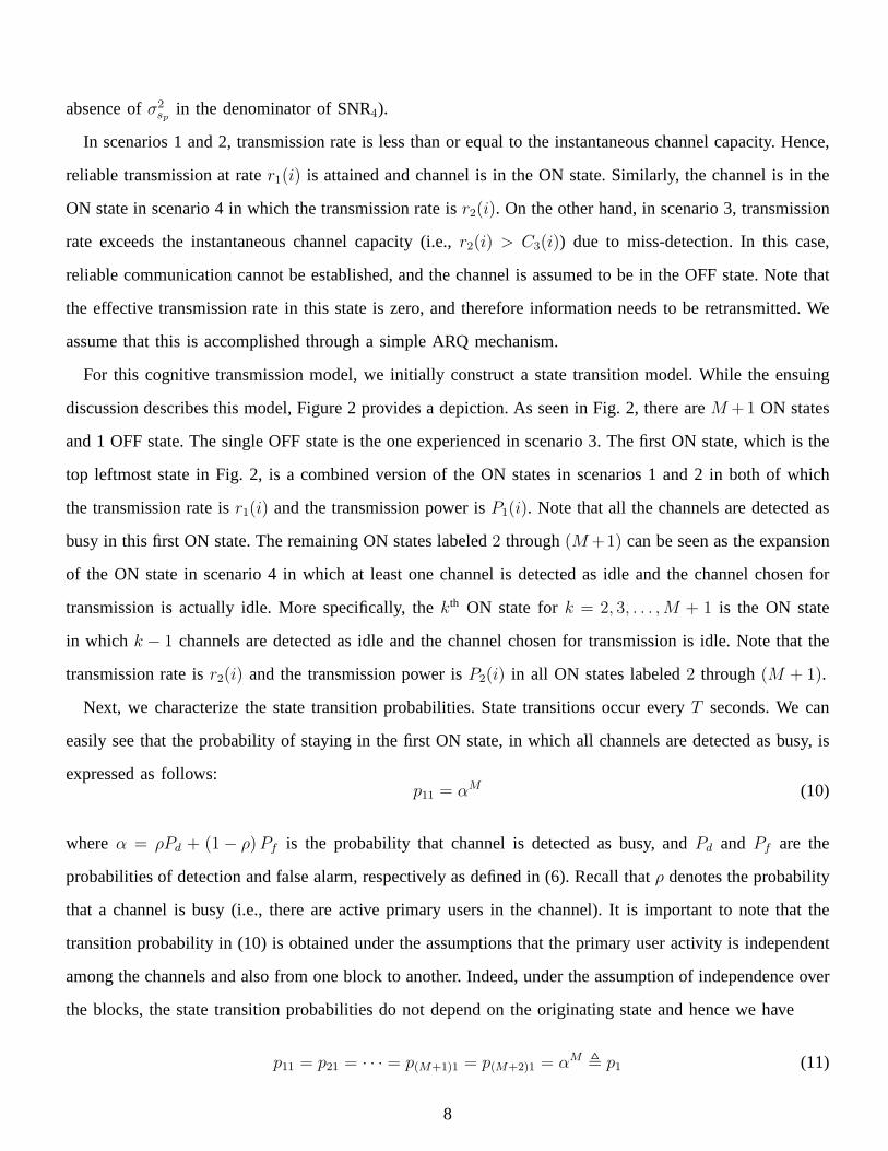
Fig. 5, we display similar results whenIavg = −10dB. Hence, secondary users operate under more stringent
interference constraints. In this case, we note thatM = 2 gives the highest throughput while the performance
with M = 1 is strictly suboptimal.
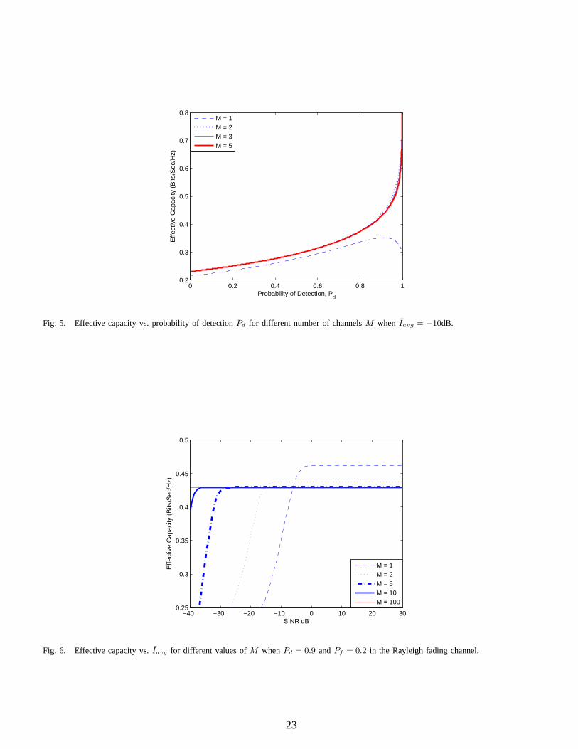
In Fig. 6, we show the effective capacities as a functionIavg (dB) for different values ofM whenPd = 0.9
andPf = 0.2. Confirming our previous observation, we notice that as the interference constraint gets more
strict and henceIavg becomes smaller, a higher value ofM is needed to maximize the effective capacity.
For instance,M = 10 channels are needed whenIavg < −30dB. On the other hand, for approximately
Iavg > −6dB, havingM = 1 gives the highest throughput.
Above, we have remarked that increasing the number of available channels from which the transmission
channel is selected provides no benefit or can even degrade the performance of secondary users under certain
conditions. On the other hand, it is important to note that increasingM always brings a benefit to the primary
users in the form of decreased probability of interference.In order to quantify this type of gain, we consider
below the probability that the channel selected for transmission is actually busy and hence the primary user
in this channel experiences interference:
Pint = P(
channel selectedfor transmissionis actually busy
)
= P(
channel selectedfor transmissionis actually busy
and all channels aredetected as busy
)
+ P(
channel selectedfor transmissionis actually busy
and at least one channelis detected as idle
)
(44)
= PS1 + PS3 (45)
= ρ1− αM − Pd + Pdα
M−1
1− α. (46)
Note thatPint depends onPd and alsoPf throughα = ρPd + (1 − ρ)Pf . It can be easily seen that this
interference probabilityPint decreases with increasingM whenPd > Pf . As M goes to infinity, we have
limM→∞ Pint = ρ1−Pd
1−α. Indeed, in this asymptotic regime,Pint becomes zero with perfect detection (i.e.,
with Pd = 1). Note that secondary users transmit (ifP1 > 0) even when all channels are detected as busy.
As M → ∞, the probability of such an event vanishes. Also, havingPd = 1 enables the secondary users to
avoid scenario 3. Hence, interference is not caused to the primary users.
18

In Fig. 7, we plotPint vs. the detection probability for different values ofM . We also display how the
false alarm probability evolves asPd varies from 0 to 1. It can be easily seen that whilePint = ρ when
M = 1, a smallerPint is achieved for higher values ofM unlessPd = 1. On the other hand, as also
discussed above, we immediately note thatPint monotonically decreases to 0 asPd increases to 1 whenM
is unbounded (i.e.,M → ∞).
B. Nakagami Fading
Nakagami fading occurs when multipath scattering with relatively large delay-time spreads occurs. There-
fore, Nakagami distribution matches some empirical data better than many other distributions do. With this
motivation, we also consider Nakagami fading in our numerical results. The pdf of the Nakagami-m random
variabley = |h| is given byfy(y) = 2Γ(m)
(m2σ2
y
)m
y2m−1e−my2
2σ2y wherem is the number of degrees of freedom.
If both zsp andz have the same number of degrees of freedom, we can express thepdf of x = zzsp
as follows:
fx(x) =Γ(2m)xm−1
(x+ 1)2mΓ(m)2. (47)
Note also that Rayleigh fading is a special case of Nakagami fading whenm = 1. In our experiments, we
consider the case in whichm = 3. Now, we can express the cdf ofx for m = 3 as
Fx(x) = 1 +15
(x+ 1)4−
10
(x+ 1)3−
6
(x+ 1)4. (48)
In Fig. 8, we plot effective capacity vs.Iavg (dB) for different values ofM whenPd = 0.9 andPf = 0.2.
Here, we again observe results similar to those in Fig. 6. We obtain higher throughput by sensing more than
one channel in the presence of strict interference constraints on cognitive radios.
VII. CONCLUSION
In this paper, we have studied the performance of cognitive transmission under QoS constraints and
interference limitations. We have considered a scenario inwhich secondary users sense multiple channels
and then select a single channel for transmission with rate and power that depend on both sensing decisions
and fading. We have constructed a state transition model forthis cognitive operation. We have meticulously
identified possible scenarios and states in which the secondary users operate. These states depend on sensing
decisions, true nature of the channels’ being busy or idle, and transmission rates being smaller or greater
than the instantaneous channel capacity values. We have formulated and imposed an average interference
19

constraint on the secondary users. Under such interferenceconstraints and also statistical QoS limitations
in the form of buffer constraints, we have obtained the maximum throughput through the effective capacity
formulation. Therefore, we have effectively analyzed the performance in a practically appealing setting in
which both the primary and secondary users are provided withcertain service guarantees. We have determined
the optimal power adaptation strategies and the optimal channel selection criterion in the sense of maximizing
the effective capacity. We have had several interesting observations through our numerical results. We have
shown that improving the reliability of channel sensing expectedly increases the throughput. We have noted
that sensing multiple channels is beneficial only under relatively strict interference constraints. At the same
time, we have remarked that sensing multiple channels can decrease the chances of a primary user being
interfered.
REFERENCES
[1] V. Asghari and S. Aissa, “Rate and Power Adaptation for Increasing Spectrum Efficiency in Cognitive Radio Networks,”IEEE International
Conference on Communications, Dresden, Germany, Jun. 14-18, 2009.
[2] L. Musavian and S. Aissa, “Capacity and Power Allocationfor Spectrum-Sharing Communications in Fading Channels,”IEEE Trans.
Wireless Commun., Vol. 8, No. 1, pp. 148-156, Jan. 2009.
[3] A. Ghasemi and E. Sousa, “Spectrum Sensing in Cognitive Radio Networks: The Cooperation-Processing Tradeoff,”Wireless Comm. and
Mobil Comp., Vol. 7, Iss. 9, pp. 1049-1060, 17 May 2007.
[4] Y.-C. Liang, Y. Zheng, E. C. Y. Peh, and A. T. Hoang, “Sensing-throughput tradeoff for cognitive radio networks,”IEEE Trans. Wireless
Commun., Vol. 7, No. 4, pp. 1326-1337, Apr. 2008.
[5] Z. Quan, S. Cui, A. H. Sayed, and H. V. Poor, “Wideband Spectrum Sensing in Cognitive Radio Networks,”Proc. of IEEE International
Conference on Communications, Beijing, China, May 19-23, 2008.
[6] L. Musavian and S. Aissa, “Adaptive Modulation in Spectrum-Sharing Systems with Delay Constraints,”IEEE International Conference
on Communications, Dresden, Germany, Jun. 14-18, 2009.
[7] L. Musavian and S. Aissa, “Quality-of-Service Based Power Allocation in Spectrum-Sharing Channels,”IEEE Global Communication
Conference, New Orleans, LA, USA, Nov. 30 - Dec. 4, 2008.
[8] S. Akin and M.C. Gursoy, “Effective Capacity Analysis ofCognitive Radio Channels for Quality of Service Provisioning,” IEEE Global
Communication Conference, Honolulu, Hawaii, Nov. 30 - Dec. 4, 2009.
[9] C.-S. Chang,Performance Guarantees in Communication Networks, New York: Springer, 1995.
[10] H. V. Poor,An Introduction to Signal Detection and Estimation, 2nd ed., Springer-Verlag, 1994.
[11] D. Wu and R. Negi, “Effective Capacity: A Wireless Link Model for Support of Quality of Service,”IEEE Trans. Wireless Commun., vol.
2, no. 4, pp. 630-643. July 2003.
[12] L. Liu and J.-F. Chamberland, “On The Effective Capacities of Multiple-Antenna Gaussian Channels,”IEEE International Symposium on
Information Theory, Toronto, 2008.
[13] C.-S. Chang and T. Zajic, “Effective bandwidths of departure processes from queues with time varying capacities,”Proceedings of IEEE
Infocom, pp. 1001-1009, 1995
[14] S. Boyd and L. Vandenberghe, Convex optimization. Cambridge, U.K.: Cambridge Univ. Press, 2004.
20

0 1 2 3 4 50
0.1
0.2
0.3
0.4
0.5
0.6
0.7
0.8
0.9
1
Energy Detection Threshold, γ
Pro
babi
lity
of D
etec
tion,
Pd a
nd F
alse
Ala
rm, P
f
Pf, N=10−4 sec
Pd, N=10−4 sec
Pf, N=10−3 sec
Pd, N=10−3 sec
Pf, N=10−2 sec
Pd, N=10−2 sec
Fig. 1. Probability of DetectionPd and False AlarmPf vs. Energy Detection Threshold
Fig. 2. State transition model for the cognitive radio channel. The numbered label for each state is given on the lower-right corner of the boxrepresenting the state.
21

0 0.2 0.4 0.6 0.8 10
0.1
0.2
0.3
0.4
0.5
0.6
0.7
0.8
0.9
1
Pro
abab
ility
pf S
cena
rios
Probability of Detection, Pd
S1, M = 1
S2, M = 1
S3, M = 1
S4, M = 1
S1, M = 10
S2, M = 10
S3, M = 10
S4, M = 10
Fig. 3. Probability of different scenarios vs. probabilityof detectionPd for different number of channelsM .
0 0.2 0.4 0.6 0.8 10.2
0.3
0.4
0.5
0.6
0.7
0.8
Probability of Detection, Pd
Effe
ctiv
e C
apac
ity (
Bits
/Sec
/Hz)
M = 1M = 5M = 10M = 20
Fig. 4. Effective capacity vs. probability of detectionPd for different number of channelsM when Iavg = 0dB.
22
0 0.2 0.4 0.6 0.8 10.2
0.3
0.4
0.5
0.6
0.7
0.8
Effe
ctiv
e C
apac
ity (
Bits
/Sec
/Hz)
Probability of Detection, Pd
M = 1M = 2M = 3M = 5
Fig. 5. Effective capacity vs. probability of detectionPd for different number of channelsM when Iavg = −10dB.
−40 −30 −20 −10 0 10 20 300.25
0.3
0.35
0.4
0.45
0.5
SINR dB
Effe
ctiv
e C
apac
ity (
Bits
/Sec
/Hz)
M = 1M = 2M = 5M = 10M = 100
Fig. 6. Effective capacity vs.Iavg for different values ofM whenPd = 0.9 andPf = 0.2 in the Rayleigh fading channel.
23

0 0.2 0.4 0.6 0.8 10
0.02
0.04
0.06
0.08
0.1
Probability of Detection, Pd
Inte
rfer
ence
Pro
babi
lity,
Pin
t
0 0.2 0.4 0.6 0.8 10
0.2
0.4
0.6
0.8
1
Probability of Detection, Pd
Pro
babi
lity
of F
alse
Ala
rm, P
f
M=1M=2M=5M=10M=20M=∞
Fig. 7. Pint vs. correct detection probabilityPd for different number of channelsM in the upper figure. False alarm probabilityPf vs. correctdetection probabilityPd in the lower figure.
−40 −30 −20 −10 0 10 20 30
0.3
0.32
0.34
0.36
0.38
0.4
0.42
0.44
0.46
0.48
0.5
SINR dB
Effe
ctiv
e C
apac
ity (
Bits
/Sec
/Hz)
M = 1M = 2M = 5M = 10M = 100
Fig. 8. Effective capacity vs.Iavg for different values ofM whenPd = 0.9 andPf = 0.2 in the Nakagami-m fading channel withm = 3.
24