and motor glitters /andrew coates - amazon s3s... · and motor gliders /andrew coates new edition...
TRANSCRIPT

and Motor Glitters /Andrew Coates

ICiBttattg afn

Jane's World Sailplanes and Motor Gliders

Jane's World Sailplanesand Motor Gliders /Andrew Coates
New edition
Jane's Publishing Company London • Sydney

Copyright © Andrew Coates 1978, 1980First published in 1978This edition published in 1980 byJane's Publishing CompanyMacdonald and Jane's Publishing Group LimitedPaulton House, 8 Shepherdess WalkLondon Nl 7LW
Printed in Great Britain by Netherwood Dalton & Co Ltd
Designed by Paul Minns
ISBN 0 71060017 8

Contents
Photograph credits "Introduction 'Australia "Austria 1 2Brazil 18Canada 20Czechoslovakia 21Finland 23France 29West Germany 43India 113Italy 116Japan 120Netherlands 122Poland 123Romania 135South Africa 139Switzerland 140United Kingdom 146USA 172USSR 195Yugoslavia 198 International gliding records 201 FAI World Gliding Championships 1937-1978 202Index by country 203 Index of aircraft types 205

Photograph credits
Aero Svet: Page 199 Akaflieg Braunschweig: Page 44 Roger Barrett: Page 197 Charles E. Brown: Page 29 Caproni Vizzola: Page 117via Andrew Coates: Pages 12, 13, 14, 16, 21, 23, 26, 37, 47, 48, 50, 52, 54, 55, 56, 57,64,65,66,80,82,84,88, 90, 91, 92,93, 94, 95, 96, 97, 98, 99, 103, 105, 107, 108, 109, 110, 119, 122, 123, 125, 126, 128, 130, 132, 135, 137, 139, 140, 141, 143, 144, 145, 147, 148, 149, 150, 151, 154, 155, 156, 157, 159, 160, 161, 165, 166, 168, 170, 174, 176, 181, 183 Coventry Gliding Club: Page 77 J. B. Cynk: Pages 124, 127 Eiri Avion: Page 24 N. Ellison: Pages 162, 163, 171 Flow Technology 2000 Ltd: Page 31 Jim Foreman (via Soaring Society of America): Page 173 John Glossop: Pages 22, 68, 72, 106 Wojciech Gorgolewski: Page 134 D. Gossett: Page 171 J. M. Gradidge: Pages 136, 172 Grob: Page 67 Rauni Heinanen: Page 25 Anne Ince: Pages 83, 194, 200via Jane's All the World's Aircraft: Pages 9, 10, 17, 18, 19, 27, 28, 30, 32, 33,34, 36,39,40,41,43,46,49, 51,58,69, 70, 71, 74, 76, 79, 100, 101, 112, 113, 114, 115, 118, 120, 121, 131, 133, 138, 175, 182, 190, 192, 198
D. Kibbe: Page 185Howard Levy: Page 180Dr D. J. Marsden: Page 20M. McGeorge: Page 86Lorna Minton: Pages 62, 153Monnett: Page 186Oberlerchner: Page 15Cyril Peckham: Page 146Philip Pegler: Page 169Vico Rosaspina: Page 116Peter Ross: Pages 81, 87Scheibe: Pages 75, 78Schempp-Hirth: Pages 85, 89Schleicher (via Sailplane & Gliding): Page 104Peter Selinger: Page 142Schweizer: Pages 188, 189, 191, 193Brian Service: Page 35Slings by: Page 167Hans Smit: Pages 45, 73, 102Soaring Society of America: Page 179Start + Plug: Page 111G. Sunderland: Page 11Peter Taylor: Page 38G. Uveges: Pages 129, 177, 178, 183Peter Warren: Page 164Wassmer: Page 42Ann Welch: Page 152C. mils: Pages 53, 195U. H. Walter: Pages 59, 60, 61, 63

Introduction
The complete history of gliding is impossible to relate in a few short sentences. For centuries man had dreamed of spreading his wings and soaring like a bird but it was not to be until the closing years of the nineteenth century that experimenters like Otto Lilienthal in Germany and Octave Chanute in the USA first succeeded in cheating gravity - if only for a short time - in their crude and dangerous hang-gliders. But credit for building the first true controlled glider must go to the acknowledged pioneers of powered flight, Orville and Wilbur Wright, who made numerous flights over the sand dunes at Kitty Hawk, North Carolina, in their 1902 glider.By the mid-1920s, pilots were regularly returning flight times measured in hours, generally by using the up-currents around hills to slope-soar. It was not long, however, before they learned how to use thermals to gain the height necessary for cross-country flying. Most of this pioneering work was done in Germany, a country with a particularly strong gliding movement centred at the Wasserkuppe in the Rhon district. In fact, most of the credit for early aerodynamic advances in sailplane design must go to the German Akafliegs which, by the mid-1939s, were designing streamlined cantilever-winged aircraft with enclosed cockpits and long tapered wings, the forebears of today's sailplanes.The Second World War forced something of a recession on the development of gliding as a sport and the machines of the 1950s were little different from those of the pre-war years, although there were a few war-surplus training gliders about. The great revolution in sailplane design and construction was to come about in the 1960s with the marriage of special laminar-flow wing sections to glassfibre as a building material. Glassfibre confers great structural strength for relatively low weight and has the added advantage of being extremely smooth, essential where drag has to be kept to a minimum. It is also quite easy to work, and several amateur-built sailplanes use glassfibre as the prime material. Thus, by the end of that decade, sailplanes had evolved into sleek, comfortable machines, often of great beauty, capable of phenomenal performance, yet with handling characteristics that made them as safe to fly for relatively inexperienced sport pilots as for the most dedicated competition fliers.But sailplane design has not stood still and the last decade has witnessed some startling advances in the quest for better and better performance. The modern competition machine can incorporate an impressive array of performance aids, ranging from camber-changing flaps on the wing trailing edge, which can be drooped to provide extra drag for landing or cranked up marginally to reduce drag for high-speed cross-country flying between thermals, to water ballast tanks in the wings which increase the gross weight and aid penetration. The number of pilots completing flights of more than 1,000 km (620 ml) has increased dramatically; of the 33 FAI Diplomas awarded, twelve have been claimed since the
beginning of 1976.Not all gliding is competitive of course, and large numbers of people fly simply for the sheer pleasure of it all. Their aircraft tend to be less aerodynamically advanced and usually more spartan in their equipment; these gliders form the bulk of the 191 types described in this book. Drawn from twenty nations, they embrace historic pre-war gliders as well as a number of experimental 'one-off' and home-built designs. Also included are a number of motor gliders, a relatively new breed of aircraft that has evolved through the need to dispense with the ground-crew and launching aids necessary for conventional glider operations. For convenience, the contents have been divided alphabetically by country, and each entry consists of a short technical description, table of data and both a specially prepared three-view drawing and a photograph. The author would like to acknowledge the valuable help which has been received from many different sources all over the world, and from the many friends, both personal and in gliding clubs and the sailplane industry, without whom this book could not have been compiled. Thanks are due to Mrs G. Bryce-Smith, Editor of Sailplane and Gliding, the official journal of the British Gliding Association; Mrs R. Harwood, Mr C. Wills and John Taylor of Jane's All the World's Aircraft for the loan of photographs, and to the many individual photographers credited at the front of this book; and not least to my Editor, Paul Ellis, for all his help.
Andrew Coates ARAeSHertfordshire
April 1978
Introduction to new edition
Jane's World Sailplanes and Motor Gliders, first published in 1978, has been substantially revised and updated to produce this edition. Seventeen new aircraft are included, drawings have been amended to take account of modifications to existing types, and there are many new photographs.

Schneider ES 52 Kookaburra /Australia
Edmund Schneider, who built the Grunau Baby in Germany and was one of the pioneer sailplane manufacturers, was invited by the Gliding Federation of Australia to set up a sailplane factory in Australia after the Second World War. He first produced the Kangaroo two-seater, which flew in 1953, followed by the Grunau Baby 4, the Kookaburra, Nymph, Kingfisher, Arrow and Boomerang. The ES 52 Kookaburra is a two-seat trainer and is used by the majority of Australian gliding clubs. The original Kookaburra first flew in 1952, and the ES 52B in 1959. The model B is an improved version with the wing span increased from 11.7m (38 ft 4V2 in) to 14.86 m (48 ft 9 in), and is fitted
with a nose wheel instead of a skid to ease ground handling. The cockpit has been enlarged and a wheel-brake is incorporated.The fuselage is constructed from plywood-covered wooden frames and stringers. The one-piece blown canopy is hinged aft and there is a window on each side under the wing root to improve visibility. The three-piece wing is of conventional wooden construction with two spars. The aircraft is semi-aerobatic.
Data ES 52 KookaburraManufacturer SchneiderFirst flight June 1954Wing span 11.7 m (38 ft 4V2 in)Length 7.9 m (25 ft 11 in)Height 1.38m (4ft 6V2 in)Wing area 15.0 m2 (161.5 sq ft)Wing section Gottingen 549/M-12Aspect ratio 9.13Empty weight 220 kg (485 Ib)Max weight 393 kg (866 Ib)Water ballast NoneMax wing loading 26.2 kg/m2 (5.36 Ib/sq ft)Max speed 119 kt (220 km/h)Stalling speed 36 kt (67 km/h)Min sinking speed at 39 kt (72 km/h) 1.05 m (3.4 ft)/secMax rough air speed 81.5 kt (151 km/h)Best glide ratio at 44 kt (81 km/h) 20

Australia / Schneider ES GOB Super Arrow
The Super Arrow is a single-seat Standard Class sailplane designed by Harry Schneider, son of the late founder of the company. The ES GOB Super Arrow, which first flew in September 1969, is a development of the ES 59 Arrow, which was commissioned by the Gliding Federation of Australia. The ES GOB is identical to the ES 60 Boomerang, designed in 1964 for competition flying, except for the tail unit. The boomerang-shaped all-flying tailplane of the ES 60, positioned one third up the fin, has been replaced on the ES 60B by a conventional tailplane and elevator located at the base of the fin. The unusual feature of the ES 59 Arrow is that the wing is
constructed in one piece, wingtip to wingtip. It consists of a moulded plastic leading edge with birch plywood covering back to 60% chord. Metal Schempp-Hirth airbrakes are fitted. The fuselage is a ply-covered semi-monocoque structure with glassfibre fairings and features a non-retractable landing wheel with brake. The cockpit is lined and the canopy is hinged sideways. An adjustable back-rest and rudder pedals are incorporated.
Data ES 60B Super ArrowManufacturer SchneiderFirst flight September 1969Wing span 15.0 m (49 ft 2l/2 in)Length 7.04 m (23 ft 1 in)Height 1.52 m (5 ft 0 in)Wing area 12.87 m2 (138.6 sq ft)Wing section Wortmann FX-61-184/60-126Aspect ratio 17.5Empty weight 221.5 kg (488 Ib)Max weight 347 kg (765 Ib)Water ballast NoneMax wing loading 26.96 kg/m2 (5.52 Ib/sq ft)Max speed 121 kt (225 km/h)Stalling speed 32.5 kt (60 km/h)Min sinking speed at 40 kt (75 km/h) 0.7 m (2.3 ft)/secMax rough air speed 89 kt (165 km/h)Best glide ratio at 49 kt (90 km/h) 31
10

Sutherland MOBA-2C / Australia
In 1972 the MOBA-2A, designed by an aircraft engineer, Gary Sutherland, was one of the two winners of an Australian Gliding Federation competition to design a 13 m (42 ft 8 in) sailplane which could be built in a small workshop with limited tools. The MOBA-2C is an improved version of the 15 m MOBA-2B. There is less emphasis on cheapness in the design of the MOBA-2C, resulting in a versatile and ambitious sailplane.The fuselage, of the elongated pod and boom type, is an all-metal semi-monocoque structure, with a unique glassfibre cockpit shell which, with the canopy, slides forward on rollers and tracks to provide access to the cockpit.
Armrests are provided and the control column isside-mounted.The high-set three-piece wings and T-tail are of mixedconstruction, with aluminium box-section spars, plywoodribs, plastic foam and glassfibre skins. The flaps are ofaluminium but the ailerons, tailplane and elevator are ofwood. The landing gear consists of a retractable mono wheeland a tailwheel.Still under construction in 1979, the prototype was expectedto make its first flight that year.
Data MOBA-2CManufacturer Gary SutherlandFirst flight 12 December 1979Wing span 15.0 m (49 ft 2 x/2 in)Length 6.78 m (22 ft 3 in)Height 1.32 m (4ft 4 in)Wing area 9.08 m 2 (97.7 sq ft)Wing section Wortmann FX-67-K-150Aspect ratio 24.74Empty weight 226 kg (499 Ib)Max weight 331 kg (730 Ib)Max wing loading 36.5 kg/m2 (7.48 Ib/sq ft)Max speed 105 kt (194.5 km/h)Stalling speed 42 kt (78 km/h)Min sinking speed at 45 kt (83 km/h) 0.61 m (2.0 ft)/secMax rough air speed 88 kt (163 km/h)Best glide ratio at 50 kt (93 km h) 37
11

Austria / Alpla-Werke AVo 68 Samburo
The Samburo is a low-wing motor glider designed for training, cross-country and recreational flying. It was designed by Werner Vogel with help from Prof. Dr. Ernst Zeibig of Vienna and built at the recently established glider department of the Alpla-Werke. It has a fabric-covered steel- tube frame fuselage and conventional tail. The aft section of the large two-piece canopy slides back to provide access over the wing. The wings are of wood and fabric construction and incorporate spoilers. They fold to 10 m (32 ft 9V2 in) for hangarage.Seating is side-by-side and dual controls are provided. The landing gear includes a fixed main wheel, steerable tail wheel
and small wing support wheels on nylon legs. The mainwheel brake can also be used as a parking brake.The Limbach engine is situated in the nose and drives atwo-blade variable-pitch propeller. The AVo 60 is a lightervariant powered by a 60 hp engine driving a fixed pitchpropeller. It uses less fuel and has a smaller fuel tank.Performance is similar to that of the AVo 68 with theexception of a slower rate of climb.Sixteen Samburos had been built by the end of 1977.
Data AVo 68Manufacturer Alpla-WerkeFirst flight 1971Wing span 16.7 m (54 ft 9Vz in)Length 7.9 m (25 ft 11 in)Height 1.82 m (5 ft 11 ¥2 in)Wing area 20.7 m2 (222.8 sq ft)Wing section Gottmgen 549/NACA 642Aspect ratio 13.6Empty weight 470 kg (1,036 Ib)Max weight 685 kg (1,510 Ib)Water ballast NoneMax wing loading 31.4 kg/m2 (6.43 Ib/sq ft)Max speed 92 kt (170 km/h)Stalling speed 32.5 kt (60 km/h)Min sinking speed at 40 kt (74 km/h) 0.85 m (2.79 ft)/secBest glide ratio at 43 kt (80 km/h) 24Power plant Limbach, 60 hp
T-O run 150-180 m (492-590 ft) Rate of climb 2.8 m (9.2 ft)/sec
12

Brditschka HB-3 / Austria
H.W. Brditschka of Linz, Austria, currently produces two powered sailplanes, the single-seat HB-3 and the larger two-seat HB-21.The wing of the HB-3 is based on the design of Ing. Fritz Raab for the Krahe sailplane and is constructed from red pine, spruce and birch ply. The HB-3 is suitable for training and for flying in mountainous terrain, having a short take-off run and good rate of climb. Three prototypes were built, the first of which flew in June 1971.This unusual motor glider has a cantilever all-wood high wing, all-wood ailerons and upper-surface spoilers. The fuselage consists of a steel-tube frame with glassfibre
covering. The tail unit is joined to the fuselage by two steel tubes, the lower one running below the propeller to the base of the fuselage and the upper one running through the centre of the propeller. The structure is wire-braced. The Rotax 642 two-stroke engine drives a Hoffmann two-blade fixed-pitch propeller via a belt.In 1973 an HB-3 became the first self-launching glider to be electrically powered. This version, known as the MB-E1, uses one 8-10 kW (13 hp) Bosch electric motor.
Data HB-3BRManufacturer BrditschkaFirst flight June 1971Wing span 12.0 m (39 ft 4V2 in)Length 7.0 m (22 ft 1 l x/2 in)Height 2.95 m (9 ft 8 in)Wing area 14.22 m2 (153.1 sq ft)Wing section Gottingen 758/Clark YAspect ratio 11.1Empty weight 255 kg (562 Ib)Max weight 372 kg (820 Ib)Water ballast NoneMax wing loading 26.2 kg/m2 (5.36 Ib/sq ft)Max speed 95 kt (175 km/h)Stalling speed 32.5 kt (60 km/h)Min sinking speed 1.15 m (3.8 ft)/secBest glide ratio at 43 kt (80 km/h) 21Power plant Rotax 642 2-stroke, 30.6 kW (41 hp)
T-O run 100 m (328 ft)Rate of climb at S/L 180 m (590 ft)/minRange 700 km (378 nm)
13

Austria / Brditschka HB-21
The HB-21 is a two-seat development of the HB-3 motor glider (page 13) and has the same arrangement of propeller allowing the upper tail boom to pass through the propeller boss.The three-piece wings are constructed from birch ply with laminated beech spars and incorporate wooden ailerons and upper-surface spoilers. The tail is of conventional wooden construction with fabric-covered control surfaces. The fuselage is similar to that of the HB-3 but is of increased length. It consists of a tubular steel frame with glassfibre covering and incorporates a roomy heated cockpit with two seats set in tandem, covered by a high-domed three-piece
canopy hinged to open sideways.As with the smaller HB-3 a choice of power units is available:the HB-21 L is powered by a 48.5 kW (65 hp)VW-Westermayer 1600G flat-four; the HB-21 R uses a 30.6kW (41 hp) Rotax 642 flat-twin engine, either driving aHoffmann HO 14-175 B 117 LD two-blade fixed-pitchpropeller. A 54 litre (11.9 Imp gallon) aluminium fuel tank issituated in the wing.Twelve HB-21s had been sold by early 1978. One took partin the Sixth German Motor Glider Competition in 1976.
Data HB-21 RManufacturer BrditschkaFirst flight 1973Wing span 16.24 m (53 ft 3V2 in)Length 7.9 m (25 ft 11 in)Height 2.6 m (8 ft 6V4 in)Wing area 18.98 m2 (204.3 sq ft)Wing section Wortmann FX-61-184/60-126Aspect ratio 13.9Empty weight 418 kg (922 Ib)Max weight 640 kg (1,411 Ib)Water ballast NoneMax wing loading 33.7 kg/m2 (6.9 Ib/sq ft)Max speed 140 kt (260 km/h)Stalling speed 35.5 kt (66 km/h)Min sinking speed at 43 kt (80 km/h) 0.8 m (2.6 ft)/secBest glide ratio at 54 kt (100 km/h) 28Power plant Rotax 642 2-stroke, 30.6 kW (41 hp)
T-Orun 170 m (558 ft)Rate of climb at S/L 132 m (433 ft)/minRange 650 km (350 nm)
14

Oberlerchner Mg 19 / Austria
After the Second World War, Austrian industrialist Joseph Oberlerchner promoted the re-establishment of sailplane manufacture and was responsible for producing the Mg 19, a development of the pre-war Mg 9. Ing. Erwin Musger, designer of the Mg series, had established and sustained pre-war Austria as a significant producer of sailplanes. His first design, the Mg 2, appeared in 1930 and was a cantilever shoulder-wing glider with gull wings spanning 18m (59ft OVi in). It was folio wed in 1931 by the Mg 4, the first Austrian high performance glider, which gave rise to a series of appreciable distance flights. A later development was the Mg 10.
In 1935 Musger designed the two-seat Mg 9, in which he set up the Austrian duration record of 8.09 hours in 1936. On 10 September 1938 a world duration record of 40 hours 51 minutes was established, also in an Mg 9. The Mg 12 training glider was produced just before the outbreak of war. The Mg 19 itself is a two-seat tandem trainer with a low-set gull wing of conventional wood and fabric construction. The prototype flew for the first time in November 1951, and many of this successful and popular trainer were built and are still flying.
Data Mg 19aManufacturer Josef OberlerchnerFirst flight November 1951Wing span 17.6 m (57 ft 9 in)Length 8.04 m (26 ft 4V2 in)Height 1.65 m (5 ft 6 in)Wing area 21.0 m2 (226.1 sq ft)Wing section Gottingen 549/676Aspect ratio 14.2Empty weight 298 kg (657 Ib)Max weight 480 kg (1,058 Ib)Water ballast NoneMax wing loading 22.9 kg/m2 (4.69 Ib/sq ft)Max speed 97 kt (180 km/h)Stalling speed 27 kt (50 km/h)Min sinking speed at 33.5 kt (62 km/h) 0.65 m (2.1 ft)/secMax rough air speed 70 kt (130 km/h)Best glide ratio at 36 kt (67 km/h) 27.8
15

Austria / Oberlerchner Mg 23
Experience gained with the successful Mg 19 (page 15) was used by Erwin Musger in designing the high performance Mg 23, which first flew in June 1955.The Mg 23 is a single-seat sailplane of conventional plywood construction. It has single-spar wooden wings with the spar set well behind the leading edge and layers of plywood stiffening forward of the spar. This and the close rib spacing of 125 mm (5 in) facilitate production of smooth polished surface areas. The wings are fitted with wooden Schempp-Hirth airbrakes.The fuselage consists of a plywood shell with a reinforced nose and a Plexiglas canopy.
The landing gear consists of a single wheel with brake, a nose skid which uses rubber to provide a certain amount of shock absorption, and a bow-shaped tail skid. The Mg 23 repeated the success of the Mg 19 by winning the Austrian State Championships and improving upon a number of national records. It was also a landmark in that it signalled the start of the Austrian national team and helped establish Austria among the contenders to be reckoned with in World Championships.The last sailplane to be built by Josef Oberlerchner was the Mg 23 SL (described below), which appeared in 1962 with a taller fin, longer canopy and lowered landing wheel.
Data Mg 23 SLManufacturer Josef OberlerchnerFirst flight April 1962Wing span 16.4 m (53 ft 9a/2 in)Length 7.11 m (23 ft 4 in)Wing area 14.21 m2 (153 sq ft)Wing section NAG A 6 3i 315Aspect ratio 18.54Empty weight 240 kg (529 Ib)Max weight 360 kg (794 Ib)Water ballast NoneMax wing loading 25.3 kg/m2 (5.18 Ib/sq ft)Max speed 119 kt (220 km/h)Stalling speed 32.5 kt (60 km/h)Min sinking speed at 37 kt (68 km/h) 0.66 m (2.2 ft)/secMax rough air speed 70 kt (130 km/h)Best glide ratio at 42.5 kt /79 km/h) 32
16

Standard Austria / Austria
The standard Austria, which won the 1960 OSTIV prize for the best Standard Class sailplane, was commissioned by the Austrian Aero Club. The designer, Riidiger Kunz, was aiming to produce a sailplane with a relatively low wing loading and a high lift/drag ratio, and consequently had to devise a completely new method of construction. The Standard Austria is built entirely of wood with the exception of the nose section, the pilot's seat and the tail-cone, all of which are glassfibre. The large fixed landing wheel with its disc brake is situated in front of the centre of gravity. The wood-and-fabric V-tail is all-moving and incorporates geared tabs. The wooden wing is of
stressed-skin construction without spars and is fabric covered from 65% chord to the trailing edge. The great strength of this high performance sailplane, together with its good flying characteristics, make the Standard Austria especially suitable for cloud flying. The 1964 version of the Standard Austria, the model SH, was fitted with a new wing with an Eppler 266 wing section. This modification improves performance at speeds between 32 and 54 kt (60 to lOOkm/h).
Data Standard AustriaManufacturer Austrian Aero ClubFirst flight July 1959Wing span 15.0 m (49 ft 2Vi in)Length 6.2 m (20 ft 4 in)Wing area 13.5 m 2 (145.3 sq ft)Wing section NACA 652415Aspect ratio 16.7Empty weight 205 kg (452 Ib)Max weight 323 kg (712 Ib)Water ballast NoneMax wing loading 23.93 kg/m2 (4.9 Ib/sq ft)Max speed 135 kt (250 km/h)Stalling speed 30 kt (55 km/h)Min sinking speed at 37.5 kt (70 km/h) 0.7 m (2.3 ft)/secMax rough air speed 75.5 kt (140 km/h)Best glide ratio at 56.5 kt (105 km/h) 34
17

Brazil / EEUFMG CB-2 Minuano
The Brazilian gliding movement operates under somewhat difficult conditions not Only because of the geography of the country but also because poor roads hamper retrieval. This, added to the country's distance from the main centres of sailplane manufacture, has contributed to the patchwork development of the sport. Nevertheless, there have been several indigenous designs, among them the Quero Quero II, the two-seat Neiva and the CB-2 Minuano. The Minuano was designed by Professor Claudio Barros and built at the Air Research Centre of Engineering at Minhas Gerais University. Construction started in 1971 and the aircraft first flew on 20 December 1975.
A single-seat high performance sailplane, the Minuano has cantilever high-set wings utilising a single aluminium spar. The covering is a plywood/glassfibre honeycomb sandwich. The plain flaps and ailerons are of similar construction. There are no airbrakes but the flaps deflect up to 90°. The fuselage consists of an all-wood semi-monocoque structure. The unsprung monowheel landing gear is manually retractable.
Data CB-2 MinuanoManufacturer EEUFMG (CEA)First flight December 1975Wing span 15.0 m (49 ft 2¥2 in)Length 7.0 m (22 ft llVi in)Height 1.43 m (4ft 8V4 in)Wing area 10.2 m2 (109.8 sq ft)Wing section Wortmann FX-61 -163/60-126Aspect ratio 22.0Empty weight 214 kg (472 Ib)Max weight 304 kg (670 Ib)Water ballast NoneMax wing loading 29.8 kg/m2 (6.1 Ib/sq ft)Max speed 140 kt (260 km/h)Stalling speed 35 kt (65 km/h)Min sinking speed at 39 kt (72 km/h) 0.55 m (1.8 ft)/secMax rough air speed 86.5 kt (160 km/h)Best glide ratio at 48.5 kt (90 km/h) 38
18

IPD Urupema / Brazil
The best known Brazilian-built sailplane outside its native country is the Urupema, which took part in the 1968 World Championships at Leszno and in those of 1970 at Marfa, Texas, where it was placed twenty-second out of forty competitors in the Standard class.The design of this 15-metre high performance single-seat sailplane was started in 1964 by a group of engineers and students at the Centre Tecnico de Aeronautica (CTA) under the leadership of Guido Pessotti. This group also work on powered aircraft and were responsible for the 8-metre Periquito 2 sailplane in 1956. This long-nosed glassfibre and wood built sailplane has
cantilever shoulder wings, with a forward sweep of 1° 22' at quarter chord, which incorporate DFS airbrakes. The fuselage is a semi-monocoque wooden structure with a very low ground incidence. The conventionally sited tail assembly incorporates an all-moving tailplane with anti-balance tabs. Like the wings, construction is of wood and honeycomb paper sandwich. The pilot is seated in a reclining position in a long slim cockpit reminiscent of the Foka, and covered by a one-piece clear detachable canopy. The cockpit features adjustable rudder pedals, head rest, thigh support and ventilation system. Landing gear consists of a non-retractable wheel with brake.
Data 6505 UrupemaManufacturer IPD/PARFirst flight January 1968Wing span 15.0 m (49 ft 2¥2 in)Length 7.45 m (24 ft 5% in)Height 1.52 m (4 ft 11 1/! in)Wing area 12.0 m2 (129.2 sq ft)Wing section Wortmann FX-05-171/121Aspect ratio 18.8Empty weight 230 kg (507 Ib)Max weight 310 kg (683 Ib)Water ballast NoneMax wing loading 25.83 kg/m2 (5.29 Ib/sq ft)Max speed 138 kt (255 km/h)Stalling speed 33 kt (61 km/h)Min sinking speed at 42 kt (78 km/h) 0.66 m (2.2 ft)/secMax rough air speed 86 kt (160 km/h)Best glide ratio at 51 kt (95 km/h) 36
19
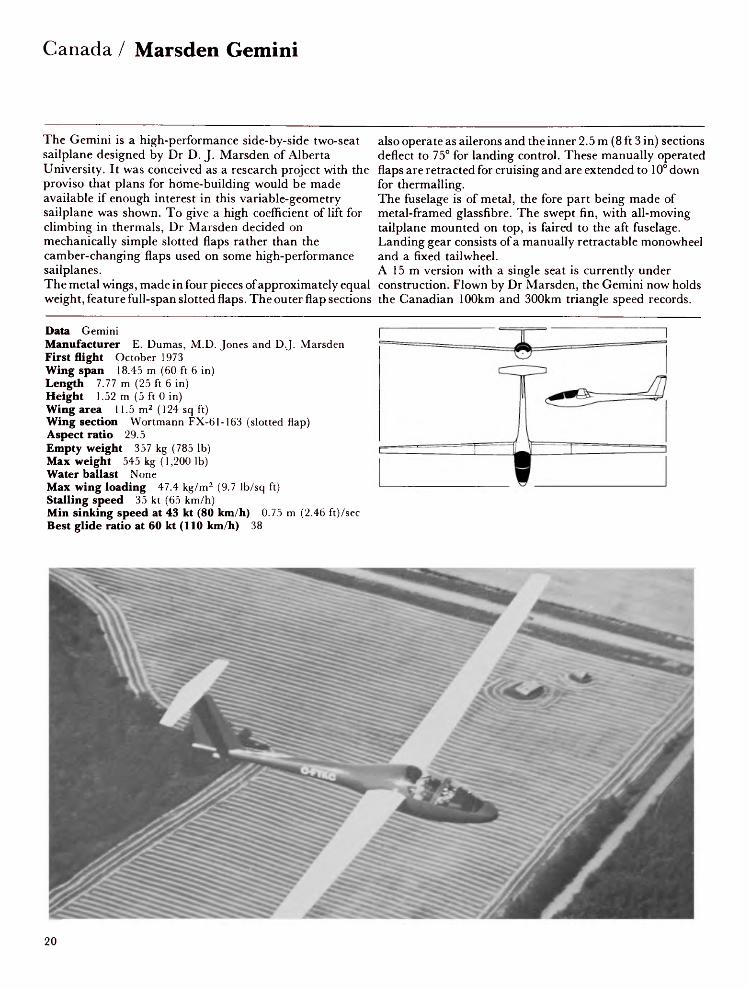
Canada / Marsden Gemini
The Gemini is a high-performance side-by-side two-seat sailplane designed by Dr D. J. Marsden of Alberta University. It was conceived as a research project with the proviso that plans for home-building would be made available if enough interest in this variable-geometry sailplane was shown. To give a high coefficient of lift for climbing in thermals, Dr Marsden decided on mechanically simple slotted flaps rather than the camber-changing flaps used on some high-performance sailplanes.The metal wings, made in four pieces of approximately equal weight, feature full-span slotted flaps. The outer flap sections
also operate as ailerons and the inner 2.5 m (8 ft 3 in) sections deflect to 75° for landing control. These manually operated flaps are retracted for cruising and are extended to 10° down for thermalling.The fuselage is of metal, the fore part being made of metal-framed glassfibre. The swept fin, with all-moving tailplane mounted on top, is faired to the aft fuselage. Landing gear consists of a manually retractable monowheel and a fixed tailwheel.A 15 m version with a single seat is currently under construction. Flown by Dr Marsden, the Gemini now holds the Canadian 100km and 300km triangle speed records.
Data GeminiManufacturer E. Dumas, M.D. Jones and D.J. MarsdenFirst flight October 1973Wing span 18.45 m (60 ft 6 in)Length 7.77 m (25 ft 6 in)Height 1.52 m (5 ft 0 in)Wing area 11.5 m 2 (124 sq ft)Wing section Wortmann FX-61-163 (slotted flap)Aspect ratio 29.5Empty weight 357 kg (785 Ib)Max weight 545 kg (1,200 Ib)Water ballast NoneMax wing loading 47.4 kg/m 2 (9.7 Ib/sq ft)Stalling speed 35 kt (65 km/h)Min sinking speed at 43 kt (80 km/h) 0.75 m (2.46 ft)/secBest glide ratio at 60 kt (110 km/h) 38
20

LET Blanik / Czechoslovakia
Since the first L-13 Blanik was rolled out in March 1956, thousands of glider pilots all over the world have received their training in this tandem-seat aircraft. By the summer of 1977 about 2,500 Blaniks had been built, of which more than 2,000 were for export. Production continues. Designed by Karel Dlouhy, the Blanik has all-metal single-spar wings with an auxiliary rear spar carrying the hinges and tracks, and DPS airbrakes and Fowler type flaps. The semi-monocoque fuselage is constructed in two halves and riveted together in the vertical plane. The only non- metal parts are the fabric coverings on the control surfaces. The Blanik is fully stressed for aerobatics and this feature,
together with its sound construction, excellent flyingqualities, durability and ease of servicing, have contributedto its popularity.This aircraft has appeared no less than thirteen times in theFAI world record list as well as setting many nationalrecords. In 1969 the Chilean pilot Alijo Williamson wasawarded the FAI Lilienthal medal for his 5 hr 51 min flightacross the Andes in a Blanik.In 1969 a small quantity was built of a powered version, theL-13J, using an Avia Ml50 Jawa 3-cylinder engine of 42 hp,but this version is not in series production.
Data L-13 BlanikManufacturer LETFirst flight March 1956Wing span 16.2 m (53 ft 1% in)Length 8.4 m (27 ft 6% in)Height 2.09 m (6 ft 10 in)Wing area 19.15 m2 (206.2 sq ft)Wing section NAG A 63i A615/612Aspect ratio 13.7Empty weight 292 kg (644 Ib)Max weight 500 kg (1,102 Ib)Water ballast NoneMax wing loading 26.1 kg/m2 (5.34 Ib/sq ft)Max speed 130 kt (240 km/h)Stalling speed 32.4 kt (60 km/h)Min sinking speed at 45 kt (83 km/h) 0.84 m (2.8 ft)/secMax rough air speed 78 kt (145 km/h)Best glide ratio at 50 kt (93 km/h) 28.2
21

Czechoslovakia / VSO 10
The Czechoslovakian VSO 10 was the winner of the first International Club Class competition, held in Sweden in summer 1979. In a field of 33 the VSO 10C took first and second places, piloted by M. Brunecky and J. Vavra respectively. The VSO 10 was designed as a single-seat Standard Class sailplane but, to comply with Club Class rules, the retractable landing wheel was locked down and covered with a large glassfibre fairing. This version (photo) had the suffix C added to its designation. Designed by Jan Janovec and his team in 1972 and embodying experience gained with the VSB 66S, the V-tail 15 m single-seater which flew in 1970, the VSO 10 has
notably clean lines. Work on three prototypes began at Vyvojova Skupina Orlican, Chocen, in 1975 and the first flew on 26 October 1976.The VSO 10 is of mixed construction, comprising a glassfibre cockpit shell and aluminium alloy rear fuselage, with a steel tube structure carrying the wings and undercarriage attachments. The metal T-tail has a fabric-covered elevator and rudder. The cantilever shoulder-set wing is a single-spar all-wood structure incorporating wooden slotted ailerons and metal DFS airbrakes on the upper surfaces.
Data VSO 10Manufacturer Vyvojova Skupina OrlicanFirst flight October 1976Wing span 15.0 m (49 ft 2 l/2 in)Length 7.0 m (23 ft)Height 1.20 m (3 ft 11V4 in)Wing area 12.0 m 2 (129.167 sq ft)Wing section Wortmann FX-61-163/FX-60-126Aspect ratio 18.75Empty weight 234.4 kg (516.76 Ib)Max weight 380 kg (837.76 Ib)Water ballast NoneMax wing loading 31.67 kg/m 2 (6.49 Ib/sq ft)Max speed 140 kt (260 km/h)Stalling speed 37 kt (68 km/h)Min sinking speed at 39 kt (72 km/h) 0.63 m (2.07 ft)/secMax rough air speed 88 kt (163 km/h)Best glide ratio at 51 kt (94 km/h) 36.2
22

Eiri PIK-20D / Finland
The PIK-20 is the latest development in the long series of PIK sailplanes designed by Pekka Tammi. It started with a group of enthusiasts at the Helsinki Institute of Technology who in 1971 designed and built a glassfibre tug, inspiring others to investigate the possibilities of glassfibre sailplanes. The PIK-20 is a 15m Unrestricted Class sailplane incorporating flaps with different settings for speed flying and thermalling. It first flew in October 1973. In 1975 the manufacturers changed their name to Eiri Avion and were producing the PIK-20B (photo), which features interconnecting flaps and ailerons, 140 kg (309 Ib) water ballast capacity, pneumatically sealed side-hinged canopy,
and optional carbon-fibre wing spars. The flaps move between ± 12° for normal flying and lower to 90° for full braking action and landing. The PIK-20B has won several national championships and took the first three places in the Standard Class at the 1976 World Championships in Finland. About 150 have been built.The PIK-20D is the current production version, featuring carbon-fibre wing spars, a more pointed nose and upper-surface airbrakes. The flaps operate from — 12° to + 16°. The rudder area was increased by moving the tailplane 12 cm (4.7 in) forward. The 20D first flew in 1976 and by the summer of 1979 some 200 had been built.
Data PIK-20DManufacturer Eiri AvionFirst flight April 1976Wing span 15.0 m (49 ft 2 l/2 in)Length 6.45 m (21 ft 2 in)Height 1.45 m (4ft Sin)Wing area 10.0 m 2 (107.7 sq ft)Wing section Wortmann FX-67-K-170/150Aspect ratio 22.5Empty weight 220 kg (480 Ib)Max weight 450 kg (992 Ib)Water ballast 140 kg (309 Ib)Max wing loading 45kg/m2 (9.21 Ib/sq ft)Max speed 158 kt (292 km/h)Stalling speed 32 kt (60 km/h)Min sinking speed at 39 kt (73 km/h) 0.56 m (1.84 ft)/secMax rough air speed 130 kt (240 km/h)Best glide ratio at 63 kt (117 km/h) 42
23

Finland / Eiri PIK-20E
The chief designer of Eiri Avion, Jukka Tervamaki, has adapted the PIK-20D to incorporate an engine. This aircraft is designated the PIK-20E and meets the OSTIV airworthiness regulations for powered sailplanes. The power unit is a 31.6 kW (43 hp) Rotax 503 two-stroke piston engine which drives a two-blade wooden propeller. An electric starter is fitted. The engine is mounted on a pylon aft of the cockpit and is completely retractable by means of a handwheel situated on the starboard side of the cockpit. The carbon fibre-reinforced fuselage is similar to that of the 20D except for the cockpit, which has been lengthened by 80 mm to accommodate the 33 litre fuel tank behind the pilot's seat.
The original tailwheel has been replaced by a steerable wheel mounted on a steel sprung skid, and wingtip nylon wheels are fitted. The wing, swept back by 1° 36', is fitted with large upper-surface airbrakes and the span of the tailplane has been increased by 0.4 m.The prototype first flew in November 1976, powered by a 22.4 kW (30 hp) Kohler 440 cc engine. The production machine, with the Rotax engine, flew in March 1978 and went into production in the summer of that year.
Type PIK-20EManufacturer Eiri AvionCountry of origin FinlandFirst flight November 1976Wing span 15.0 m (49 ft 2 1/! in)Length 6.53 m (21 ft 5 in)Wing area 10.0 m 2 (107.7 sq ft)Wing section Wortmann FX-67-K-1707150717Aspect ratio 22.5Empty weight 290 kg (639 Ib)Max weight 470 kg (1,036 Ib)Water ballast 120 kg (265 Ib)Max wing loading 47.0 kg/m 2 (9.63 Ib/sq ft)Max speed 154 kt (285 km/h)Stalling speed 36 kt (66 km/h)Min sinking speed at 42 kt (77 km/h) 0.6 m (2 ft)/secBest glide ratio at 63 kt (117 km/h) 41Power plant Rotax 501, 37.3 kW (50 hp) 500 cc
T-Orun 450 m (1,476 ft) Rate of climb 4.0 m (13 ft)/sec
24

Fibera KK-1 Utu / Finland
Designed by Dipl.-Eng. Ahto Anttila of Oy Fibera Ab, the prototype KK-1 Utu first flew on 14 August 1964. Since then four other prototypes, designated KK-lb, c, d, and e, have been built, each with various constructional techniques and structural modifications. The aim was to investigate the structural application of plastic laminates stabilised with polyurethane foam. As a result the superiority of plastic materials, especially when compared with wood, has become evident.The wing consists of a glassfibre reinforced plastic (GRP) sandwich shell with a plastic foam core, a single I-spar and no ribs. The upper surface-hinged ailerons are of GRP shell
construction with plastic foam stiffening. Trailing-edge flaps are fitted on both wings. The fuselage is a monocoque double-shell structure with glassfibre laminates. The tail fin is moulded integrally with the fuselage and the tailplane is mounted on the top of the fin. A non-retractable monowheel with drum brake is fitted.A total of 22 examples had been built by early 1970, but the company is no longer in existence and only a few Utus are still flying.
Data KK-leUtuManufacturer FiberaFirst flight 1964Wing span 15.0 m (49 ft 2¥2 in)Length 6.5 m (21 ft 4 in)Height 1.22 m (4ft 0 in)Wing area 11.3 m2 (121.6 sq ft)Wing section NAG A 633618/63612Aspect ratio 20.0Empty weight 200 kg (441 Ib)Max weight 310 kg (683 Ib)Water ballast NoneMax wing loading 27.43 kg/m2(5.62 Ib/sq ft)Max speed (smooth air) 135 kt(250 km/h)Stalling speed 34 kt (63 km/h)Min sinking speed at 40 kt (74 km/h)0.6 m (2 ft)/secMax rough air speed 113 kt(210 km/h)Best glide ratio at 43.5 kt (81 km/h)35
25

Finland / IKV-3 Kotka
Mr Tuomo Tervo, who supervised the construction of the PIK-3C, and Mr Jorma Jalkanen, who with Tervo was involved in the design and building of the PIK-16 Vasarrta and Havukka sailplanes, have together designed the single-seat high performance IKV-3. Construction of the prototype by members of IKV, the flying club of Vasama, was started in mid-1965, supervised by K.K. Lehtovaara Oy; the IKV-3 was later manufactured in series by Ilmailukerho.The cantilever single-spar wooden wings are ply skinned and the ailerons and trailing-edge flaps are constructed from ply covered plastic foam. The airbrakes, of which there are two
pairs on each wing, operate on both upper and lower surfaces and are constructed of light alloy. The fuselage is a conventional wooden structure with a long slender glassfibre nose and flush canopy. The ply tailplane is of the variable incidence type. The rudder and elevator are fabric covered. The landing gear consists of a retractable monowheel with drum brake and a detachable tail wheel. On 28 May 1968 a Scandinavian record of 602 km (325 nm) was set up by S. Hamalanen in an IKV-3.
Data IKV-3 KotkaManufacturer IKVFirst flight June 1966Wing span 18.2 m (59 ft 8l/2 in)Length 7.75 m (25 ft 5 in)Height 2.0 m (6 ft 6V2 in)Wing area 17.0 m2 (183 sq ft)Wing section Wortmann FX-62-K153/FX-60-126Aspect ratio 19.0Empty weight 340 kg (750 Ib)Max weight 450 kg (992 Ib)Water ballast NoneMax wing loading 26.47 kg/m2 (5.42 Ib/sq ft)Max speed 135 kt (250 km/h)Stalling speed 28 kt (52 km/h)Min sinking speed at 37.5 kt (70 km/h) 0.53 m (1.7 ft)/secMax rough air speed 93 kt (172 km/h)Best glide ratio at 54 kt (100 km/h) 38
26

PIK-3C Kajava / Finland
The PIK series takes its name from the Polyteknikkojen Ilmailukerho, which was founded at Helsinki Technical University in 1931. The series began in 1945 but the PIK-3 was the first type to be produced in series. It was designed by Lars Norrmen and Ilkka Lounama as a small cheap sailplane suitable for construction by flying clubs. The prototype first flew in the summer of 1950. The oval fuselage is of wood with diagonal ply covering. The conventional tail has a ply-covered fin and stabilisers. The detachable Plexiglas canopy runs back as far as the main spar. The high-set single-spar two-part wings are of wood and incorporate flaps and ailerons. Production PIK-3Bs,
developed by Aush Koskinen, omitted the flaps and substituted airbrakes. Twenty PIK-3A and 3B models have been built.The PIK-3C Kajava was a high performance version of the PIK-3B. The basic 13-metre wing was increased to 15 metre span and modifications were made to the Standard class rules. The wing structure was completely revised but the PIK-3B fuselage was retained but with a new canopy fitted. The prototype PIK-3C first flew on 20 May 1958 and the design was adopted for series production by S. Ilmailuliitto in the winter of 1958 under the supervision ofTuomo Tervo.
Data PIK-3C KajavaManufacturer IlmailukerhoFirst flight May 1958Wing span 15.0 m (49 ft 2Vi in)Length 6.6 m (21 ft 7% in)Height 1.0 m (3 ft 3 in)Wing area 13.1 m2 (141 sq ft)Wing section Gottingen 549/693Aspect ratio 17.1Empty weight 165 kg (364 Ib)Max weight 280 kg (617 Ib)Water ballast NoneMax wing loading 21.4 kg/m2 (4.38 Ib/sq ft)Max speed 135 kt (250 km/h)Stalling speed 30 kt (55 km/h)Min sinking speed at 35 kt (65 km/h) 0.61 m (2 ft)/secMax rough air speed 78 kt (145 km/h)Best glide ratio at 40.5 kt (75 km/h) 30
27

Finland / PIK-16C Vasama
In 1963 the OSTIV prize for the best Standard class sailplane was awarded to the Finnish designed and built PIK- 16C Vasama. It was designed by Tuomo Tervo, Jorma Jalkanen and Kurt Hedstrom and was a development of the PIK-3A Kajava. It first flew in June 1961. The single-seat PIK- 16C has a conventional tail unit in place of the V-tail of the prototype, and the wings have been improved by using a sandwich type construction at the leading edge. The wing is built entirely of pine and birch wood and a striking feature of its design is its exceptional thinness, chosen to attain the optimum glide angle. The spoilers operate on top and bottom surfaces of the wing and
the plain ailerons are of ply-covered wooden construction. The highly polished surface areas contribute to this sailplane's high performance. The monocoque fuselage is of wooden construction with a glassfibre nose. The landing gear comprises a non-retractable monowheel with brake, and a skid.The PIK-16C was produced by K.K. Lehtovaara Oy, and a total of fifty-six PIK-16A, B and Cs was built. Several Finnish records were set with the Vasama and at the 1963 World championships in Argentina, Juhani Horma was placed third.
Data PIK-16C VasamaManufacturer K.K. Lehtovaara OyFirst flight June 1961Wing span 15.0 m (49 ft 2Vi in)Length 5.97 m (19 ft 7 in)Height 1.45m (4ft 9 in)Wing area 11.7 m2 (126 sq ft)Wing section Wortmann FX-05-188/NACA 682615Aspect ratio 19.2Empty weight 190 kg (419 Ib)Max weight 300 kg (661 Ib)Water ballast NoneMax wing loading 25.64 kg/m2 (5.25 Ib/sq ft)Max speed 135 kt (250 km/h)Stalling speed 33.5 kt (62 km/h)Min sinking speed at 39.5 kt (73 km/h) 0.59 m (1.9 ft)/secMax rough air speed 92 kt (170 km/h)Best glide ratio at 46 kt (85 km/h) 34
28
Breguet 901 /France
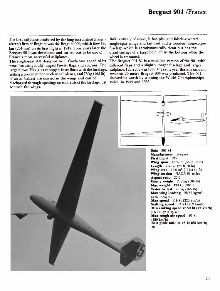
The first sailplane produced by the long established French aircraft firm of Breguet was the Breguet 900, which flew 470 km (254 nm) on its first flight in 1949. Four years later the Breguet 901 was developed and turned out to be one of France's most successful sailplanes.The single-seat 901 designed by J. Cayla was ahead of its time, featuring multi-hinged Fowler flaps and ailerons. The large blown Plexiglas canopy is inset flush with the fuselage, setting a precedent for modern sailplanes, and 75 kg (165 Ib) of water ballast are carried in the wings and can be discharged through openings on each side of the fuselagejust beneath the wings.
Built entirely of wood, it has ply- and fabric-covered single-spar wings and tail unit and a wooden monocoque fuselage which is aerodynamically clean but has the disadvantage of a large hole left in the bottom when the wheel is retracted.The Breguet 901-SI is a modified version of the 901 with different flaps and a slightly longer fuselage and larger tailplane. It first flew in 1956, the same year that the tandem two-seat 20-metre Breguet 904 was produced. The 901 showed its worth by winning the World Championships twice, in 1954 and 1956.
Data 901-SIManufacturer BreguetFirst flight 1956Wing span 17.32 m (56 ft 10 in)Length 7.57 m (24 ft 10 in)Wing area 15.0 m2 (161.5 sq ft)Wing section NACA 63 seriesAspect ratio 20.0Empty weight 265 kg (584 Ib)Max weight 430 kg (948 Ib)Water ballast 75 kg (165 Ib)Max wing loading 28.67 kg/m2(5.87 Ib/sq ft)Max speed 119 kt (220 km/h)Stalling speed 33.5 kt (62 km/h)Min sinking speed at 39 kt (72 km/h)0.60 m (2.0 ft)/secMax rough air speed 97 kt(180 km/h)Best glide ratio at 46 kt (85 km/h)36
29

France / Breguet 905 Fauvette
Of all the firms which have built sailplanes, Breguet is one of the best known outside France because of the success of its designs. The Breguet 905 Fauvette is a single-seat Standard Class V-tail sailplane designed by J Cayla. At the time of its manufacture it was available either complete or as a kit of parts for home assembly.The fuselage consists of three main parts: a nose section of moulded plastic foam housing the pilot's seat, instrument panel and flying controls; a steel-tube centre fuselage covered with a moulded polystyrene skin which carries cockpit attachment points, towing hook and wing; and a rear fuselage of plywood/foam sandwich construction. The
sandwich is composed of 6 mm plywood with 8 mm of Klegecel, an expanded plastic. The Klegecel is pre-formed under heat and the result is an almost perfect shape of considerable strength and lightness. The sandwich is also used for the fixed tail surfaces which fold to the vertical position for trailering. The cantilever single-spar wings are of ply and Klegecel with metal and Klegecel sandwich airbrakes.On 12 June 1959 Rear Admiral N. Goodhart set a United Kingdom distance record in a Fauvette by flying a distance of 625 km (337 nm).
Data 905 FauvetteManufacturer BreguetFirst flight 1958Wing span 15.0 m (49 ft 2% in)Length 6.22 m (20 ft 4% in)Wingarea 11.25 m2 (121.1 sq ft)Wing section NACA 63420/63613Aspect ratio 20.0Empty weight 155 kg (342 Ib)Max weight 275 kg (606 Ib)Water ballast NoneMax wing loading 24.5 kg/m2 (5.02 Ib/sq ft)Max speed 108 kt (200 km/h)Stalling speed 29 kt (54 km/h)Min sinking speed at 35 kt (65 km/h) 0.65 m (2.Max rough air speed 92 kt (170 km/h)Best glide ratio at 42 kt (78 km/h) 30
ft)/sec
30

CARMAM JP. 15-36 Aiglon / France
The JP. 15-36 is a restricted Standard Class sailplane designed by Robert Jaquet and Jean Pettier, Technical Directors of CARMAM, as a private venture. It is built by CARMAM, who have been building the M-100 and M-200 under licence for Morelli of Italy and have manufactured sailplane components for Glasflugel of W. Germany. The prototype JP. 15-36 made its first flight on 14 June 1974. The sailplane is of all glassfibre/Klegecel sandwich construction, with an all-flying tail of conventional configuration and a fixed landing wheel and cable brake. It was designed for intensive use by clubs and so has good flying qualities and safe away-landing characteristics for
inexperienced pilots. The cockpit, under a one-piece blown canopy, is large and comfortable. Both the seat and rudder pedals are adjustable in flight. The wings, fitted with Schempp-Hirth type airbrakes, are designed to allow fast and easy rigging with the aileron and airbrake controls connected automatically.The PA. 15-35 is a version designed by Jean Pettier to be suitable for amateur builders. The JP.15-36AR is a version with retractable monowheel and capacity for 80 litres of water ballast.
Data J P. 15-36 AiglonManufacturer CARMAMFirst flight June 1974Wing span 15.0 m (49 ft 2Vi in)Length 6.4 m (21 ft 0 in)Height 1.4m (4ft 7 in)Wing area 11.0 m2 (118.4 sq ft)Wing section Wortmann FX-67-K-170/67-126Aspect ratio 20.4Empty weight 200 kg (441 Ib)Max weight 390 kg (860 Ib)Water ballast NoneMax wing loading 35.5 kg/m2 (7.27 Ib/sq ft)Max speed 130 kt (240 km/h)Stalling speed 33.5 kt (62 km/h)Min sinking speed at 40.5 kt (75 km/h) 0.6 m (2 ft)/secMax rough air speed 108 kt (200 km/h)Best glide ratio at 49.5 kt (92 km/h) 36
31

France / Fauvel AV.45
The AV.45 is a single-seat tailless motor glider which first flew on 4 May 1960 powered by a 26 kW (35 hp) Nelson engine. A second prototype with a 16.5 kW (22 hp) SOLO engine was built by Societe Aeronautique Normande (SAN). The standard engine recommended for the AV.45, however, is the modified Hirth 0-280R of between 30-41 kW (40-55 hp).The single-spar wooden wing has conventional ailerons and also elevators on the trailing edge of the centre wing. Schempp-Hirth airbrakes are mounted both on upper and lower surfaces of the outer wings. The fuselage consists of a short wooden nacelle with glassfibre covering. The twin fin
and rudders are inset at the junctions of the centre section and outer wings. As with the AV.361, the AV.45 may also be fitted with a Wortmann laminar-flow wing which increases the best glide angle to 30 at a speed of 47.5 kt (88 km/h). An improved version of the AV.45, known as the AV.451, has been built. Modifications include a wing of extended span; a more tapered nose; more streamlined wheel fairings; and vertical tail surfaces of Wortmann symmetrical section.
Data AV.45Manufacturer FauvelFirst flight May 1960Wing span 13.74 m (45 ft 1 in)Length 3.59 m (11 ft 9 in)Wing area 15.95m2 (171.7 sq ft)Wing section ¥2 17%Aspect ratio 11.84Empty weight 216 kg (476 Ib)Max weight 350 kg (772 Ib)Water ballast NoneMax wing loading 21.94 kg/m2 (4.49 Ib/sq ft)Max speed 77 kt (142 km/h)Min sinking speed at 37.5 kt (70 km/h) 0.8 m (2.62 ft)/secBest glide ratio at 45.5 kt (85 km/h) 27Power plant Hirth O-280R, 30-41 kW (40-55 hp)T-O run 493 ft (150m)Rate of climb 168 m (550 ft)/min
32

Fauvel AV.222 / France
The AV.222 side-by-side two-seat tailless motor glider is a lighter and simplified version of the AV.221; both are derived from the AV.22 tailless sailplane. The AV.222 is suitable for amateur construction and plans are available from Fauvel. Glassfibre component moulds and canopies can also be supplied if required.The AV.221 and 222 can be powered by a 30 kW (39 hp) Rectimo 4AR 1200 or 45 kW (60 hp) Limbach Volkswagen conversion, driving a fixed pitch wooden propeller of 1.05 m (3 ft 5V4 in) diameter. The prototype AV.221 flew for the first time in April 1965. To improve ease of handling over rough terrain the original large single landing wheel has been
replaced by a conventional layout of twin wheels on cantilever legs of laminated glassfibre, fitted with disc brakes. There is no increase in drag from these faired wheels, and the outrigger wheels of the prototype have been removed.The wings, of wooden construction, are swept slightly forward. They are made in three sections with the centre section being mounted on the short fuselage and the outer panels attached to the centre section. The fuselage incorporates a large single fin and rudder and is fitted with a steerable tail wheel.
Data AV.222Manufacturer FauvelFirst flight April 1965Wing span 16.4 m (53 ft 9% in)Length 5.22 m (17 ft 1V2 in)Wing area 23.0 m2 (247.6 sq ft)Wing section ¥2 17%Aspect ratio 12.0Empty weight 325 kg (716 Ib)Max weight 550 kg (1,212 Ib)Water ballast NoneMax wing loading 23.91 kg/m2 (4.89 Ib/sq ft)Stalling speed 40 kt (74 km/h)Min sinking speed at 40 kt (74 km/h) 0.87 m (2.85 ft)/secBest glide ratio at 46 kt (85 km/h) 26Power plant Limbach, 45 kW (60 hp)T-Orun 110m (361 ft)Max rate of climb at S/L 180 m (591 ft)/min
33

France / Fauvel AV.361
Flying wing sailplanes have excited wide interest for many years with their obvious advantages of low drag and simplicity of design and construction. However, they have been beset with problems, chiefly connected with questions of stability, which has forced most designers to concentrate on the highly swept back design with high aspect ratio. The AV.36 Monobloc, designed and built by Charles Fauvel, has proved that the problem of stability did not really exist in practice. This sailplane was supplied in kit form in the early 1950s and more than 100 were sold to customers in 14 countries before the design was superseded by the AV.361.
In the AV.361, which first flew in 1960, the span of the wood and fabric wings has been increased from 11.95 m (39 ft 2Vz in) to 12.78 m (41 ft 1 P/4 in). Schempp-Hirth spoilers are fitted on both upper and lower wing surfaces. The new fin and rudder design on the AV.361, together with the larger ailerons, have improved control co-ordination. The fuselage consists of a short wooden nacelle and the roomy cockpit is covered by a side-opening blown Plexiglas canopy. A nose wheel and rear skid have replaced the long skid of the AV.36. Although commercial production of this aircraft ceased in 1971, plans for home constructors are still available.
Data AV.361Manufacturer FauvelFirst flight 1960Wing span 12.78 m (41 ft 11V4 in)Length 3.24 m (10 ft 7Vi in)Wing area 14.6 m2 (157.2 sq ft)Wing section ¥2 17%Aspect ratio 11.4Empty weight 122 kg (269 Ib)Max weight 258 kg (569 Ib)Water ballast NoneMax wing loading 17.67 kg/m2 (3.62 Ib/sq ft)Max speed 119 kt (220 km/h)Stalling speed 31 kt (58 km/h)Min sinking speed at 35 kt (65 km/h) 0.75 m (2.5 ft)/secMax rough air speed 85 kt (158 km/h)Best glide ratio at 45 kt (83 km/h) 26
34

Fournier RF-9 / France
Avions Fournier is a company which in the past has built light aircraft rather than motor gliders. In the mid 1960s they produced the RF-4D, constructed of wood with glassfibre fairings, and the RF-5. Sportavia, who build the Fourniers in West Germany, collaborated with Scheibe to produce the SFS-31 Milan, which is an RF-4 with a feathering propeller and the 15-metre wing of the Scheibe SF-27. The SF-27M motor glider, built by Scheibe, differs from the SFS-31 Milan in that the latter has the power unit and propeller sited in the nose cone. The RF-4, RF-5 and Milan are all lower performance motor gliders. In France, Avions Fournier designed and built the
single-seat RF-7 with wood fuselage and single-spar wooden wings covered with plywood and fabric of 9.4 m (30 ft 10 in) span. It is powered by a 65 hp Sportavia Limbach SL 1700D engine.The latest Fournier product is designated the RF-9. It is a two-seat motor glider intended for training. The accommodation is arranged side-by-side. It is powered by a 50 kW (68 hp) Limbach SL 1700E engine driving a Hoffmann two-blade variable-pitch propeller. Fuel capacity is 30 litres (6.6. Imp Gal). First flight was on 20 January 1977.
Data RF-9Manufacturer FournierFirst flight January 1977Wing span 17.0 m (55 ft 9% in)Length 7.86 m (25 ft 9 l/2 in)Wing area 18.0 m2 (193.8 sq ft)Wing section NAG A 643618Aspect ratio 16.0Empty weight 530 kg (1,168 Ib)Max weight 750 kg (1,653 Ib)Water ballast NoneMax wing loading 38.8 kg/m2 (7.59 Ib/sq ft)Max level speed at S/L 102 kt (190 km/h)Stalling speed 35.5 kt (65 km/h)Min sinking speed at 43.5 kt (80 km/h) 0.80 m (2.6 ft)/secBest glide ratio 28Power plant Sportavia Limbach SL 1700E, 50 kW (68 hp)T-O run 100 m (328 ft)
Max rate of climb at S/L Range 600 km (324 nm)
156 m (512 ft)/min
180
F-WARF

France / GEP TCV-03 Trucavaysse
The TCV-03 is a single-seat Standard Class sailplane, built by GEP (Groupe d'Etudes Georges Payre) in an attempt to produce a sailplane which has good flying characteristics and which can be sold in kit form suitable for amateur or club construction. Prototype construction started in February 1969 and the aircraft first flew on 14 July 1973. The design is based on the original Breguet 905, with modifications. These include an improved control system, reinforced trailing edges, a new slender fuselage and the deletion of the landing skid. It was designed by Dr P. Vaysse, head of the sailplane amateur construction department of the FFVV (Federation Francaise de Vol a Voile) and is his third
project. The first two were the TCV-01 and the TCV-02, which flew for the first time in August 1964 and April 1969 respectively.The TCV-03 features single-spar cantilever shoulder wings with plywood/Klegecel sandwich leading edges, slotted wooden ailerons and DFS metal airbrakes on both upper and lower surfaces. The fuselage is a conventional ply-covered wooden structure, and the tail unit features an all-moving tailplane. The landing gear consists of a fixed monowheel and tail skid, employing rubber shock absorbers.
Data TCV-03 TrucavaysseManufacturer Group d'Etudes Georges Payre (GEP)First flight July 1973Wing span 15.0 m (49 ft 2^2 in)Length 6.7 m (21 ft 11% in)Height 1.8 m (5 ft 11 in)Wing area 11.25 m2 (121.1 sq ft)Wing section NAG A 63-420/513Aspect ratio 20.0Empty weight 192 kg (423 Ib)Max weight 302 kg (666 Ib)Water ballast NoneMax wing loading 26.9 kg/m2 (5.51 Ib/sq ft)Max speed 113 kt (210 km/h)Stalling speed 27 kt (50 km/h)Min sinking speed at 32.5 kt (60 km/h) 0.8 m (2.6 ft)/secMax rough air speed 81 kt (150 km/h)Best glide ratio at 43 kt (80 km/h) 28
36

Issoire D 77 Iris / France
Siren SA, which designed the Edelweiss sailplanes and the two-seat E 78 Silene, began designing the D 77 Iris in 1973 as a single-seat training sailplane. It made its debut in 1977 and after its first flight on 26 February was exhibited at the Paris Air Show. In the same year Issoire Aviation was formed by Siren SA to produce both the E 78 Silene and D 77 Iris. The D 77 is a cantilever mid-wing sailplane using a Berlin E55-166 wing section. It is of glassfibre/plastic foam sandwich construction and incorporates airbrakes on the upper surface of each wing. The original design projected a cantilever T-tail but the production model has a conventional tail unit with tailpiane of fixed incidence and
trim tabs on both sides of the elevator. The fuselage consistsof a GRP monocoque structure, built in two halves andreinforced at the wing attachment points. A non-retractablemonowheel with Siren hydraulic brakes and tail skidcomprise the landing gear.The cockpit contains a console for the instruments and anadjustable semi-reclining seat under a long clear one-pieceflush canopy which opens sideways to starboard.The D 77 is available as either a finished aircraft or a kitwhich requires only 400 man-hours to assemble.
Data D 77 IrisManufacturer IssoireFirst flight February 1977Wing span 13.5 m (44 ft 3¥2 in)Length 6.37 m (20 ft 11 in)Height 0.9m (2ft 11V2 in)Wing area 11.4 m2 (122.7 sq ft)Wing section Berlin E-55-166Aspect ratio 16Empty weight 220 kg (485 Ib)Max weight 330 kg (728 Ib)Water ballast NoneMax wing loading 27.2 kg/m2 (5.57 Ib/sq ft)Max speed 126 kt (234 km/h)Stalling speed 32.5 kt (60 km/h)Min sinking speed at 39.5 kt (73 km/h) 0.68 m (2.23 ft)/secBest glide ratio at 48.5 (90 km/h) 33
37

France / Issoire E 78 Silene
The E 78 Silene side-by-side two-seat sailplane was developed by CERVA (Consortium Europeen de Realisation et de Ventes d'Avions) and is the first French glassfibre two-seater. The company was owned by Siren SA and Wassmer-Aviation SA. The E 78 was designed by Siren and, following the closure of Wassmer, was transferred to Issoire in late 1977. The aim was to produce a sailplane suitable for all stages of glider training from ab initio to cross-country flights. Construction was started in February 1973 and the prototype first flew at Argenton on 2 July 1974. The wings are of glassfibre/plastic foam sandwich construction, incorporating two-section ailerons of similar
material and Schempp-Hirth airbrakes operating both above and below each wing. Flaps are not fitted. The fuselage is a semi-monocoque glassfibre/plastic foam sandwich structure. The conventional tail unit incorporates a fixed incidence tailplane and trim tabs on each elevator. The pilots sit in staggered position to keep the width of the fuselage to a minimum, the starboard seat being set slightly to the rear. The Silene is available with either retractable or fixed landing wheel with hydraulic brake and shock absorber.
Data E 78 SileneManufacturer Issoire AviationFirst flight July 1974Wing span 18.0 m (59 ft 0 3/4 in)Length 7.95 m (26 ft 1 in)Height 1.5 m (4 ft 11 in)Wing area 18.0 m 2 (193.8 sq ft)Wing section Berlin E55 166Aspect ratio 18.0Empty weight 365 kg (805 Ib)Max weight 565 kg (1,246 Ib)Water ballast NoneMax wing loading 29 kg/m 2 (5.94 Ib/sq ft)Max speed 1 19 kt (220 km/h)Stalling speed 34 kt (63 km/h)Min sinking speed at 39 kt (73 km/h) 0.59 m (1.8 ft)/secBest glide ratio at 51 kt (95 km/h) 38
38
Siren Edelweiss / France
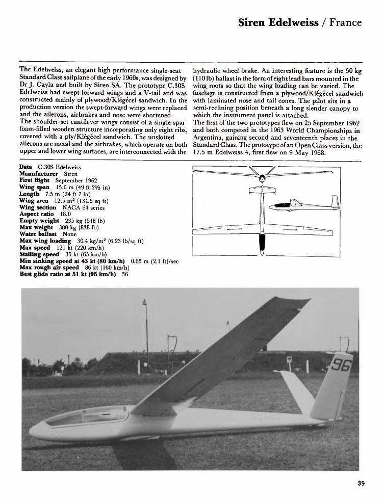
The Edelweiss, an elegant high performance single-seat Standard Class sailplane of the early 1960s, was designed by Dr J. Cayla and built by Siren SA. The prototype C.30S Edelweiss had swept-forward wings and a V-tail and was constructed mainly of plywood/Klegecel sandwich. In the production version the swept-forward wings were replaced and the ailerons, airbrakes and nose were shortened. The shoulder-set cantilever wings consist of a single-spar foam-filled wooden structure incorporating only eight ribs, covered with a ply/Klegecel sandwich. The unslotted ailerons are metal and the airbrakes, which operate on both upper and lower wing surfaces, are interconnected with the
hydraulic wheel brake. An interesting feature is the 50 kg (110 Ib) ballast in the form of eight lead bars mounted in the wing roots so that the wing loading can be varied. The fuselage is constructed from a plywood/Klegecel sandwich with laminated nose and tail cones. The pilot sits in a semi-reclining position beneath a long slender canopy to which the instrument panel is attached. The first of the two prototypes flew on 25 September 1962 and both competed in the 1963 World Championships in Argentina, gaining second and seventeenth places in the Standard Class. The prototype of an Open Class version, the 17.5 m Edelweiss 4, first flew on 9 May 1968.
Data C.30S EdelweissManufacturer SirenFirst flight September 1962Wing span 15.0 m (49 ft 2Vi in)Length 7.5 m (24 ft 7 in)Wing area 12.5 m2 (134.5 sq ft)Wing section NACA 64 seriesAspect ratio 18.0Empty weight 235 kg (518 Ib)Max weight 380 kg (838 Ib)Water ballast NoneMax wing loading 30.4 kg/m2 (6.23 Ib/sq ft)Max speed 121 kt (220 km/h)Stalling speed 35 kt (65 km/h)Min sinking speed at 43 kt (80 km/h) 0.65 m (2.1Max rough air speed 86 kt (160 km/h)Best glide ratio at 51 kt (95 km/h) 36
ft)/sec
39

France / Wassmer WA 22 Super Javelot
The Wassmer light aircraft firm, based at Issoire in Central France, also built many of France's sailplanes. The company's first essay into the market was the 16.08 m WA 20 Javelot, designed by M. Colland and built to meet an urgent need for a single-seat sailplane with good performance and straightforward construction. The first flight of the WA 20 was made in August 1956.The WA 22 Super Javelot is the Standard Class development of the WA 20 and is used in great numbers by French gliding clubs and private owners. The fuselage is a fabric-covered steel tube frame to which is bolted a glassfibre cockpit shell in three parts. The cockpit, under a new blown canopy,
incorporates a seat which can be adjusted both for height and inclination. The three-piece wing is a single-spar wooden structure with outer panels set at an angle. Quick, easy rigging is effected by pulling on a large lever, which locks the securing bolts in position. The differential wooden ailerons are in two sections, the inner section moving through a larger angle than the outer section to improve the rate of roll. Perforated wooden airbrakes operate above and below each wing and the hydraulic wheelbrake is coupled with the airbrake control lever.
Data WA 22 Super JavelotManufacturer WassmerFirst flight June 1961Wing span 15.0 m (49 ft 2V2 in)Length 7.06 m (23 ft 2 in)Height 1.9m (6 ft 3 in)Wing area 14.4 m 2 (155 sq ft)Wing section NAG A 63821 /63615Aspect ratio 15.7Empty weight 205 kg (452 Ib)Max weight 350 kg (750 Ib)Water ballast NoneMax wing loading 24.3 kg/m 2 (4.84 Ib/sq ft)Max speed 108 kt (200 km/h)Stalling speed 33 kt (61 km/h)Min sinking speed at 43 kt (80 km/h) 0.7 m (2.29 ft)/secMax rough air speed 70 kt (130 km/h)Best glide ratio 30
40

Wassmer WA 28 Espadon / France
The WA 28 Espadon (Swordfish) is the glassfibre version of the WA 26 Squale, which was a conventional wood and fabric sailplane. The wings of the WA 26 and WA 28 are identical in geometry, but the latter's are constructed from a glassfibre/plastic foam sandwich. The Schempp-Hirth airbrakes, operating both above and below the wings, are perforated and are claimed to be very effective. The reinforced polyester plastic fuselage is of oval section, accommodating the pilot in a semi-reclining position beneath a long slender one-piece Plexiglas canopy which opens sideways to port. The tail unit is of conventional shape with all-moving horizontal surfaces and spring-loaded
trimming. The seat, headrest and rudder pedals are all adjustable and ventilation is provided by swivel inlets. The instrument panel is large, housing a comprehensive set of equipment. The landing gear consists of a retractable wheel mounted forward of the centre of gravity, with hydraulic brake and an optional fixed tail wheel. Design began in 1972 and the prototype WA 28 first flew in May 1974, with the first production model flying in November of that year.
Data WA 28 Espadon (Swordfish)Manufacturer WassmerFirst flight 1974Wing span 15.0 m (49 ft 2Va in)Length 7.65 m (25 ft 1% in)Height 1.66 m (5 ft 5Va in)Wing area 12.63 m2 (136 sq ft)Wing section Wortmann FX-61-163/60-126Aspect ratio 17.82Empty weight 245 kg (540 Ib)Max weight 378 kg (833 Ib)Water ballast NoneMax wing loading 29.92 kg/m2 (6.13 Ib/sq ft)Max speed 131 kt (242 km/h)Stalling speed 36.5 kt (68 km/h)Max rough air speed 84.5 kt (157 km/h)Best glide ratio at 48.5 kt (90 km/h) 38
41

France / Wassmer WA 30 Bijave
The Wassmer WA 30 Bijave is the standard French two-seat advanced trainer and is a development of the WA 21 Javelot. Designed by M Colland, the first prototype flew on 17 December 1958. The second, improved prototype first flew on 18 March 1970, Although the type is no longer in production many are still flying, mainly in France. The pilots sit in tandem with the rear seat placed somewhat higher than the front, providing very good visibility from the rear. Each seat has an individual blown perspex canopy. The shoulder-set cantilever wings, which are in three pieces, are constructed from birch plywood reinforced with a leading edge torsion box spar and with fabric covering aft of the spar.
The Schempp-Hirth airbrakes are perforated and operate on both upper and lower surfaces of the wings. The fuselage consists of a welded steel-tube frame covered with fabric; the nose cone is glassfibre. The landing gear consists of a retractable sprung monowheel and a large skid at the nose. The wooden all-moving tailplane is a one-piece cantilever structure with large anti-balance tabs.
Data WA 30 BijaveManufacturer WassmerFirst flight December 1958Wing span 16.85 m (55 ft 3 ¥2 in)Length 9.5 m (31 ft 2 in)Height 2.74 m (9 ft 0 in)Wing area 19.2 m 2 (206.7 sq ft)Wing section NAG A 63821763615Aspect ratio 15.0Empty weight 295 kg (650 Ib)Max weight 550 kg (1,213 Ib)Water ballast NoneMax wing loading 28.6 kg/m2 (5.85 Ib/sq ft)Max speed 130 kt (240 km/h)Stalling speed 32.5 kt (60 km/h)Min sinking speed at 42 kt (78 km/h) 0.75 m (2.5 ft)/secMax rough air speed 81 kt (150 km/h)Best glide ratio at 40.5 kt (75 km/h) 30
42

Akaflieg Braunschweig SB-9 Stratus / West Germany
At the 1969 German Nationals the Brunswick Flying College (Akaflieg Braunschweig), who have built a number of high performance sailplanes, introduced a new single-seat sailplane, the SB-9 Stratus. Calculations had suggested that a wing span of 22 metres and an aspect ratio of 31.3 would provide the performance they required. The SB-9 was developed from the 18 metre SB-8 and first flew on 23 January 1969. The glide ratio of the 22 m version is 48 compared with 42 for the SB-8 and the minimum sink speed is likewise improved from 0.52 m/sec to 0.45 m/sec. This represents a 15% gain in performance, but some difficulties had to be overcome: the wing geometry, load distribution,
aileron length and rudder action posed problems and the maximum speed is limited to only 180 km/h (97 kt). Glassfibre with balsa wood support is used for the fuselage and PVC foam for the wing, which has a glassfibre roving spar to bear the stresses. The trailing-edge flaps are of the HKS type and are of elastic glassfibre construction with no hinge or gap. The tail unit is a glassfibre and balsa structure with the tailplane mounted at the tip of the fin. The landing gear consists of an unsprung retractable monowheel with drum brake. Later the wing span was reduced to 21 m (68 ft 11 in), improving the SB-9's maximum speed by 20 km/h (llkt).
Data SB-9 StratusManufacturer Akaflieg BraunschweigFirst flight January 1969Wing span 22.0 m (72 ft 2V4 in)Length 7.5 m (24 ft 7Vi in)Height 1.4m (4ft 7 in)Wing area 15.48 m 2 (166.6 sq ft)Wing section WortmannFX-62-K-153/131Aspect ratio 31.3Empty weight 314 kg (692 Ib)Max weight 416 kg (917 Ib)Water ballast NoneMax wing loading 27.0 kg/m2(5.53 Ib/sq ft)Max speed 97 kt (180 km/h)Stalling speed 32 kt (59 km/h)Min sinking speed at 39 kt (72 km/h)0.45m (1.5ft)/secMax rough air speed 97 kt(180 km/h)Best glide ratio at 46 kt (85 km/h)48
43

West Germany / Akaflieg Braunschweig SB-10 Schirokko
The Brunswick Technical University, having developed a long series of interesting experimental sailplanes, began design of this unique tandem two-seat high performance sailplane in 1969. It first flew on 22 July 1972. The SB-10 has an aspect ratio of 36 and can be flown with a wing of either 26 m or 29 m span. It is developed from the single-seat SB-9 and uses the same outer wing panels with airbrakes but the centre section, fuselage and tail unit are new designs. The wings are in five parts: the centre section, constructed of plywood, balsa wood and carbon-fibre, gives rigidity, and the outer panels and wing tips are of balsa wood and glassfibre with foam filling. The camber-changing flaps
are built of foam-filled carbon-fibre and can be drooped with the ailerons (there are three on the 29 metre version). The fuselage is a steel tube frame covered with a shell of balsa/glassfibre sandwich and light alloy at the rear. The tail unit is a sweptback structure of balsa/glassfibre sandwich with a fixed incidence tailplane. The landing gear includes an air-assisted retractable monowheel with hydraulic brake and tail skid.After some modifications, including changes to the rudder system, landing gear and airbrakes, the aircraft set a German distance record of 896 km (577 ml) on 16 April 1974.
Data SB-10Manufacturer Akaflieg BraunschweigFirst flight July 1972Wing span 29.0 m (95 ft 1% in)Length 10.36 m (33 ft 11% in)Wing area 22.95 m2 (247.1 sq ft)Wing section Wortmann FX-62-K-153/131 /60-126Aspect ratio 36.6Empty weight 577 kg (1,272 Ib)Max weight 897 kg (1,978 Ib)Water ballast 100 kg (220 Ib)Max wing loading 39 kg/m2 (7.98 Ib/sq ft)Max speed 108 kt (200 km/h)Stalling speed 35 kt (65 km/h)Min sinking speed at 40.5 kt (75 km/h) 0.41 (1.3 ft)/secMax rough air speed 108 kt (200 km/h)Best glide ratio at 48.5 kt (90 km/h) 53
44
Akaflieg Braunschweig SB-11 / West Germany
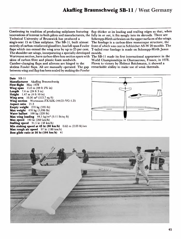
Continuing its tradition of producing sailplanes featuring innovations of interest to both pilots and manufacturers, the Technical University of Brunswick has produced a single-seat 15 m Glass sailplane. The SB-11, built almost entirely of carbon-reinforced glassfibre, has full-span Fowler flaps which can extend the wing area by up to 25 per cent. The shoulder-set wings, incorporating a specially developed Wortmann section, have carbon-fibre box-section spars with skins of carbon fibre and plastic foam sandwich. Camber-changing flaps and ailerons are hinged to the slotless Fowler flaps. All are manually operated. The gap between wing and flap has been sealed by making the Fowler
flap thicker at its leading and trailing edges so that, when fully in or out, it fits snugly into its shrouds. There are Schempp-Hirth airbrakes on the upper surfaces of the wings. The fuselage is a carbon-fibre monocoque structure, the front of which was cast in Schleicher AS-W 20 moulds. The T-tailed rear fuselage is made on Schempp-Hirth Janus moulds.The SB-11 made its first international appearance in the World Championships in Chateauroux, France, in 1978. Flown to victory by Helmut Reichmann, it showed a remarkable ability to make use of weak thermals.
Data SB-11Manufacturer Akaflieg BraunschweigFirst flight May 1978Wing span 15.0 m (49 ft 2Vi in)Length 7.4 m (24 ft 3 in)Height 1.47 m (4ft 10 in)Wing area 10.56 m2 (113.7 sq ft)Wing section Wortmann FX-62K-144/21-VG-1.25Aspect ratio 21.3Empty weight 270 kg (595 Ib)Max weight 470 kg (1,036 Ib)Water ballast 100 kg (220 Ib)Max wing loading 44.5 kg/m2 (9.11 Ib/sq ft)Max speed 140 kt (260 km/h)Stalling speed 31.5 kt (58 km/h)Min sinking speed at 43 kt (80 km/h) 0.62 m (2.03 ft)/secMax rough air speed 97 kt (180 km/h)Best glide ratio at 56 kt (104 km/h) 41
45

West Germany / Akaflieg Darmstadt D-36 Circe
Akaflieg Darmstadt's involvement with gliding started in 1909. Its successes include the Edith in 1922; the Konsul, the first 18 metre glider; the Darmstadt; the feather-weight Windspiel; the metal D-30 Cirrus; and after the war the D-34.As far back as 1954 members of the Akaflieg Darmstadt began to investigate the possibilities of using the new synthetic materials which were becoming available, and in 1961 they were experimenting with reinforced glassfibre bonded resins. Three members of the DFS, Wolfe Lemke, Gerhard Waibel and Klaus Holighaus, started work on the D-36 Circe in the Spring of 1963.
The D-36 features a streamlined fuselage with a fixed front-section canopy with detachable rear section. A large retractable landing wheel is fitted. The T-tail set a precedent for many glassfibre sailplanes. The wings incorporate Schempp-Hirth airbrakes and camber-changing flaps which operate between ±10°. The material usfd is a balsa/ glassfibre composite in the form of a sandwich. The D-36 was rolled out at Gelnhausen for its first flight in March 1964. This new design was successful in gaining second place in the World Championships at South Cerney
1965 and aroused keen interest.in
Data D-36 CirceManufacturer Akaflieg DarmstadtFirst flight March 1964Wing span 17.8 m (58 ft 3 l/2 in)Length 7.35 m (24ft 1V2 in)Wing area 12.8 m2 (137.8 sq ft)Wing section Wortmann FX-62-K-131/60-126Aspect ratio 24.0Empty weight 282 kg (622 Ib)Max weight 410 kg (904 Ib)Water ballast NoneMax wing loading 32.0 kg/m 2 (6.55 Ib/sq ft)Max speed 108 kt (200 km/h)Stalling speed 36 kt (67 km/h)Min sinking speed at 45 kt (83 km/h) 0.56 m (1.83 ft)/secMax rough air speed 108 kt (200 km/h)Best glide ratio at 50 kt (93 km/h) 44
46

Akaflieg Darmstadt D-39 / West Germany
This unique single-seat powered sailplane, created by the Darmstadt Akaflieg, looks exactly like a Standard Class high-performance sailplane except for its low-mounted wing. Its great novelty, however, lies in the retractable two-blade folding propeller, driven by twin Fichtel & Sachs modified KM 914V engines situated in the nose cone. The D-39 is an adaptation of the basic D-38 airframe, having the same glassfibre/balsa sandwich construction with ailerons of glassfibre/Klegecel foam sandwich, and Schempp-Hirth airbrakes on the upper wing surfaces. No flaps are fitted. It is equipped with a manually-retractable sprung monowheel, and accommodation comprises a
semi-reclining seat under a flush canopy, the rear section of which is detachable. The D-39 first flew on 28 June 1979.
Data D-39Manufacturer Akaflieg DarmstadtFirst flight June 1979Wing span 15.0 m (49 ft 2Va in)Length 7.15 m (23 ft 5V2 in)Height 1.02 m (3 ft 4V2 in)Wing area 11.0 m2 (118.4 sq ft)Wing section Wortmann FX-61 -184/60-126Aspect ratio 20.5Empty weight 280 kg (617 Ib)Max weight 400 kg (882 Ib)Water ballast NoneMax wing loading 36.3 kg/m2 (7.43 Ib/sq ft)Max speed 135 kt (250 km/h)Stalling speed 39 kt (72 km/h)Min sinking speed 1.0 m (3.3 ft)/secBest glide ratio at 56.5 kt (105 km/h) 36Power plant 2 x Fichtel & Sachs KM 914V, 35 kW (47 hp)
T-O run 200 m (656 ft)Rate of climb at S/L 240 m (787 ft)/minRange 500 km (269 nm)
47

West Germany / Akaflieg Miinchen Mii 13
The Mii series was developed from the two-seat Mii 10 Milan, which had been built at the Munich Akaflieg under the direction of Dipl.Ing. Scheibe. In 1935 and 1936 two prototypes, the Merlin and the Atalante, were built. The latter, with many improvements, went into series production at the Black Forest Aircraft works.The Mii 13 is of mixed construction, using wood, steel and chrome-molybdenum-tin alloy, the metal and wood parts being connected with pop-rivets. The wooden cantilever wings incorporate steel-tube flaps and steel-framed fabric-covered ailerons. The fuselage is a fabric-covered steel-frame structure of square cross-section with a
conventional wood tailplane and large windows inset intothe sides of the cockpit.From 1939 onwards many variations were introduced.Airbrakes replaced the flaps. The fuselage was altered so thatthe rear cross-section is triangular. At least four differentcanopies were used.About 150 Mii 13s were produced and 1943 saw the Mii13D-3 (photo below), with increased wing span and fuselagelength and modified fin and rudder. In May 1939 KurtSchmidt set a new German goal flight record of 482 km (260nm) in a Mii 13 Atalante.
Data Mii 13 AtalanteManufacturer Akaflieg MiinchenFirst flight 1936Wing span 16.0 m (52 ft 6 in)Length 6.02 m (19 ft 9 in)Wing area 16.16 m2 (174 sq ft)Wing section MilAspect ratio 15.85Empty weight 170 kg (375 Ib)Max weight 270 kg (595 Ib)Water ballast NoneMax wing loading 16.71 kg/m2 (3.42 Ib/sq ft)Max speed 108 kt (200 km/h)Stalling speed 27 kt (50 km/h)Min sinking speed at 29.5 kt (55 km/h) 0.6 m (2 ft)/secBest glide ratio at 35.5 kt (66 km/h) 28
48
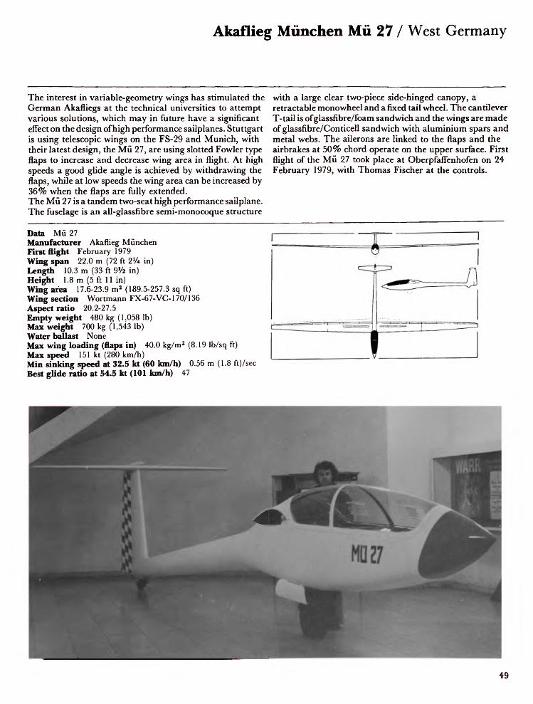
Akaflieg Miinchen Mii 27 / West Germany
The interest in variable-geometry wings has stimulated the German Akafliegs at the technical universities to attempt various solutions, which may in future have a significant effect on the design of high performance sailplanes. Stuttgart is using telescopic wings on the FS-29 and Munich, with their latest design, the Mii 27, are using slotted Fowler type flaps to increase and decrease wing area in flight. At high speeds a good glide angle is achieved by withdrawing the flaps, while at low speeds the wing area can be increased by 36% when the flaps are fully extended. The Mii 27 is a tandem two-seat high performance sailplane. The fuselage is an all-glassfibre semi-monocoque structure
with a large clear two-piece side-hinged canopy, a retractable mono wheel and a fixed tail wheel. The cantilever T-tail is of glassfibre/foam sandwich and the wings are made of glassfibre/Conticell sandwich with aluminium spars and metal webs. The ailerons are linked to the flaps and the airbrakes at 50% chord operate on the upper surface. First flight of the Mii 27 took place at Oberpfaffenhofen on 24 February 1979, with Thomas Fischer at the controls.
Data Mii 27Manufacturer Akaflieg MiinchenFirst flight February 1979Wing span 22.0 m (72 ft 2% in)Length 10.3 m (33 ft 91/* in)Height 1.8m (5ft 11 in)Wing area 17.6-23.9 m2 (189.5-257.3 sq ft)Wing section Wortmann FX-67-VC-1707136Aspect ratio 20.2-27.5Empty weight 480 kg (1,058 Ib)Max weight 700 kg (1,543 Ib)Water ballast NoneMax wing loading (flaps in) 40.0 kg/m2 (8.19 Ib/sq ft)Max speed 151 kt (280 km/h)Min sinking speed at 32.5 kt (60 km/h) 0.56 m (1.8 ft)/secBest glide ratio at 54.5 kt (101 km/h) 47

West Germany / Akaflieg Stuttgart FS-24 Phi
The Phonix was the first sailplane to be built of glassfibre. Designed and built by Stuttgart Academic Flying Group under the direction of R. Eppler and H. Nagele, it was originally developed in 1951. The aim was to reduce weight rather than increase the wing area. For this purpose balsa wood with a stiffened outer skin of paper-and-glue layers was to be used, but the project was suspended. Fortunately the Group was able to get a subsidy which made further research possible and the project was completed. By this time, glassfibre strengthened polyester resins were available. Balsa wood was retained as a filling material for the sandwich skin and glassfibre was used as an outer skin.
The monocoque fuselage is constructed in two pieces with a sandwich skin of glassfibre and balsa wood. The weight-carrying points and the rim of the canopy are strengthened with plywood. The wing attachment, controls and fittings are installed before the two pieces are glued together with overlapping glassfibre. The wings are constructed in a similar way. Ailerons, flaps and rudder are cut out after the gluing process. The Phonix first flew on 27 November 1957. The conventional tail was subsequently replaced by a T-tail and retractable landing gear was incorporated. Eight examples of the Phonix were built, all of which are still flying.
Data FS-24 Phonix-TManufacturer Akaflieg StuttgartFirst flight November 1957Wing span 16.0 m (52 ft 6 in)Length 6.84 m (22 ft 5% in)Wing area 14.36 m2 (154.6 sq ft)Wing section EC86(-3)-914Aspect ratio 17.83Empty weight 164 kg (362 Ib)Max weight 265 kg (584 Ib)Water ballast NoneMax wing loading 18.5 kg/m2 (3.79 Ib/sq ft)Max speed 97 kt (180 km/h)Stalling speed 31 kt (58 km/h)Min sinking speed at 37 kt (69 km/h) 0.51 m (1.7 ft)/secMax rough air speed 54 kt (100 km/h)Best glide ratio at 42 kt (78 km/h) 40
50

Akaflieg Stuttgart FS-29 / West Germany
A glider pilot's dream is to have polymorphic wings on his aircraft, automatically interchangeable in flight. These wings would have a high aspect ratio for thermalling and a low aspect ratio (and smaller area) for high-speed cross-country flying. Akaflieg Stuttgart is attempting to realise this ideal by the use of telescopic wings on its variable-geometry FS-29 sailplane. Designed in 1972, it first flew in June 1975.The wings consist of outer telescopic sections which slide over inner fixed sections, thus varying the span. The inner wing comprises a box spar of glassfibre/Conticell foam sandwich. A stub spar protrudes to provide a mounting for
the guide rails on which the outer panels move. Extension and retraction of the outer wing sections is manually operated by push-rods. The outer wing sections are of glassfibre/ foam/carbon-fibre sandwich. The wings incorporate plain ailerons of similar construction, and Schempp-Hirth airbrakes are fitted to the upper surfaces of the inner wings and are only effective when the outer panels are extended.The fuselage is constructed of already available components, using the frame, canopy, landing gear and tail unit of a Schempp-Hirth Nimbus 2.
Data FS-29Manufacturer Akaflieg StuttgartFirst flight June 1975Wing span 13.3-19.0 m (43 ft 7Va in-62 ft 4 in)Length 7.16 m (23 ft 5% in)Height 1.27m (4 ft 2 in)Wing area 8.56-12.65 m2 (92.2-136.2 sq ft)Wing section Wortmann FX-73-170 (inner); FX-73-170/22(outer)Aspect ratio 20.67-28.54Empty weight 357 kg (787 Ib)Max weight 450 kg (992 Ib)Water ballast NoneMax wing loading 52.6-35.6 kg/m2 (10.77-7.29 Ib/sq ft)Max speed 135 kt (250 km/h)Stalling speed 39 kt (72 km/h)Min sinking speed at 40 kt (74 km/h) 0.54 m (1.8 ft)/secMax rough air speed 135 kt (250 km/h)
Best glide ratio at 54 kt (100 km/h) 44
51

West Germany / Bolkow Phoebus
The Phoebus is derived from the Phonix, the first all-glassfibre sailplane. The Phoebus is a joint design by H. Nagele, R. Linder and R. Eppler and was built by Bolkow at Ottobrun. It first flew on 4 April 1964. The main improvements over the Phonix are better high-speed performance, simplified control mechanism, a stronger skin, an all-moving T-tail and improved gust response.The adoption of the all-moving tail with no tabs reduces drag, weight and expense, and its high position avoids the downflow from the wing.There are three versions of the Phoebus: models A, B and C. Model A, which made its first public appearance at the
World Championships at South Cerney in 1965, is the Standard Class 15 metre version incorporating a fixed landing wheel. Model B, similar to the Model A but incorporating a retractable wheel, appeared two years later. The Phoebus C features a 17 metre wing, retractable wheel and tail brake parachute.At the World Championships at Leszno, Poland, a Phoebus C, flown by Goran Ax of Sweden, was placed second and Rodolfo Hossinger of Argentina, also flying a Phoebus C, was sixth.Production of the Phoebus series was discontinued in 1970 after 253 had been built.
Data Phoebus CManufacturer BolkowFirst flight April 1967Wing span 17.0 m (55 ft 9% in)Length 6.98 m (22 ft 10% in)Wing area 14.06 m2 (151.4 sq ft)Wing section Eppler 403Aspect ratio 20.55Empty weight 235 kg (518 Ib)Max weight 375 kg (827 Ib)Water ballast NoneMax wing loading 26.7 kg/m2 (5.46 Ib/sq ft)Max speed 108 kt (200 km/h)Stalling speed 31 kt (58 km/h)Min sinking speed at 43 kt (80 km/h) 0.55m (1.8 ft)/secMax rough air speed 108 kt (200 km/h)Best glide ratio at 48.5 kt (90 km/h) 42
52

DFS Meise / West Germany
In the Spring of 1938, the International Olympic Committee decided to recognise gliding as an Olympic sport. The difficulty of judging sailplanes of many different types was to be overcome by stipulating standards to which competing aircraft had to conform; consequently the Federation Aeronautique Internationale (FAI) announced a competition for the design of such an Olympic sailplane. The specifications were: span 15m (49 ft 2Vi in); empty weight 160kg (353 Ib); payload 95 kg (209 Ib); maximum speed 200 km/h (110 kt); uniformity of building materials; fitted airbrakes; and no flaps or retractable undercarriage. The competition was held in February 1939 in Italy and
entries included two from Italy- the A1 3 and Pellicano; two from Germany- the Meise and Mil 17 Merle; and one from Poland - the Orlik. Well-known pilots from several European countries test flew these aircraft. The Meise, designed by Hans Jacobs, was the final choice. For the few months before hostilities began many nations showed interest in this sailplane and the German Aero Club supplied details of the design. Many were built in other countries, some under different names. It was produced in Spain, in France as the Nord 2000, in Great Britain, where it was known as the EoN Olympia, and in Czechoslovakia, where it was designated the Zlin-25 Sohay.
Meise Manufacturer DFS First flight 1939 Wing span 15.0 m (49 ft 2Vi in) Length 7.27 m (23 ft 10% in) Wing area 15.0 m2 (161.5 sq ft) Wing section Gottingen 549/676 Aspect ratio 15.0 Empty weight 160 kg (353 Ib) Max weight 255 kg (562 Ib) Water ballast NoneMax wing loading 17.0 kg/m2 (3.48 Ib/sq ft) Max speed 119 kt (220 km/h) Stalling speed 29.5 kt (55 km/h)Min sinking speed at 32 kt (59 km/h) 0.67 m (2.2 ft)/sec Best glide ratio at 37 kt (69 km/h) 25.5
53

West Germany / DPS Weihe
The DPS Weihe, designed by Hans Jacob in 1938, proved to be a very popular sailplane and more than 350 were built in Germany, Sweden, France, Spain and Yugoslavia. It is a wooden aircraft and uses a thin aerofoil section. Instead of the gull wings of the Reiher, from which it was developed, it has straight wings for lower production costs. For rigging the wings are fitted into the fuselage with the wingtips on the ground; the tips are then raised and the wings locked into position with a bolt.The fuselage is relatively long with a narrow cross section and though this improves its flying qualities it is at the expense of pilot comfort. The canopy was of the sectional
type but the later Weihe 50, produced by Focke-Wulf in 1950, had a one-piece streamlined canopy. The Weihe was placed fourth in the Rhon competition in 1938. In 1947 Per Axel Persson set a world height record of 8,050 m (26,411 ft), and in the 1948 World Championships 13 of the 29 competitors were flying Weihes. Even as late as 1952 and 1954 the Weihe was able to hold its own in international competitions in spite of the many new designs then appearing. In 1959, twenty years after its first flight, it set a world height record of 9,665 m (31,709 ft).
Data WeiheManufacturer DPSFirst flight 1938Wing span 18.0 m (59 ft OV2 in)Length 8.3 m (27 ft 3 in)Wing area 18.2 m 2 (195.9 sq ft)Wing section Gottingen 549/676Aspect ratio 17.8Empty weight 190 kg (419 Ib)Max weight 325 kg (716 Ib)Water ballast NoneMax wing loading 17.85 kg/m 2 (3.65 Ib/sq ft)Max speed 116 kt (215 km/h)Stalling speed 24 kt (45 km/h)Min sinking speed at 27 kt (50 km/h) 0.58 m (1.9 ft)/secBest glide ratio at 37.5 kt (70 km/h) 31
54

Glaser-Dirks DG-100 / West Germany
The D-38, predecessor to the DG-100, was designed at Akaflieg Darmstadt. It showed even better performance and handling qualities than had been expected and designer Wilhelm Dirks decided to develop a production version. He found a sponsor in private industry and with Gerhard Glaser formed the Glaser-Dirks Flugzeugbau. The single-seat D-38 GRP (glass-reinforced-plastic) sailplane flew in February 1973 and only fifteen months later, on 10 May 1974, the prototype DG-100 was rolled out for its first flight. It is basically the same as the D-38 but has a better finish and the rounded nose of the D-38 has been replaced by an aerodynamically superior pointed nose.
Lighter plastic foam is used to support the glassfibre skin instead of the balsa of the D-38. The Wortmann FX-61-184 wing section is the best known aerofoil for flapless wings. Dirks had decided against flaps since they increase only slightly the average cross-country speed, and that only on good flying days; and because the powerful upper-surface Schempp-Hirth airbrakes are simpler to operate for landing, cheaper to make and save weight.Glaser-Dirks have also built a number of examples of the DG-100G, which is generally similar to the DG-100 except that it has a tail unit similar to that of the DG-200.
Data DG-100Manufacturer Glaser-DirksFirst flight May 1974Wing span 15.0 m (49 ft 2¥2 in)Length 7.0 m (22 ft 1 iVi in)Height 1.4m (4 ft 7 in)Wing area 11.0 m 2 (118.4 sq ft)Wing section Wortmann FX-61-184/60-126Aspect ratio 20.5Empty weight 230 kg (507 Ib)Max weight 418 kg (922 Ib)Water ballast 100 kg (220 Ib)Max wing loading 38.0 kg/m2 (8.78 Ib/sq ft)Max speed 140 kt (260 km/h)Stalling speed 32.5 kt (60 km/h)Min sinking speed at 40 kt (74 km/h) 0.59 m (1.94 ft)/secMax rough air speed 140 kt (260 km/h)Best glide ratio at 56.5 kt (105 km/h) 39.2
55

West Germany / Glaser-Dirks DG-200
Despite the success of the DG-100 there remains a demand for a sailplane with flaps for the 15 m Unrestricted Class international competitions, so Glaser-Dirks have embarked on the production of a second model, the DG-200, to satisfy this requirement. The same 15 metre wing span, long slim fuselage and T-tail are featured in the DG-200, but flaps have been added and the wing area reduced. The first flight was on 22 April 1977.The tailplane on the prototype DG-100 was all-moving, incorporating a large anti-servo tab, but this was altered to a conventional fixed tailplane and elevator on both the DG-100 and DG-200. The trimmer is fitted on the control
column, which is of the parallelogram linkage type, enabling high speed flight with reduced risk of pilot-induced oscillation.The pilot is accommodated in semi-reclining position in the slim cockpit, covered by a two-piece canopy, the rear section of which is hinged to open upwards and back. The adjustable head rest is attached to the canopy hinge. The landing gear includes a retractable main wheel and a fixed tail wheel. A maximum of 120 kg (265 Ib) of water ballast is carried. In 1978 two other versions were developed: the 17 m DG-200-17 and the 13.1 m Acroracer, both with detachable wing tips to permit conversion to 15 m Class.
Data DG-200Manufacturer Glaser-DirksFirst flight April 1977Wing span 15.0 m (49 ft 2Vi in)Length 7.0 m (22 ft 11 ¥2 in)Height 1.4 m (4ft 7 in)Wing area 10.0 m 2 (107.7 sq ft)Wing section Wortmann FX-61-184/60-126Aspect ratio 22.5Empty weight 230 kg (507 Ib)Max weight 450 kg (992 Ib)Water ballast 120 kg (265 Ib)Max wing loading 45 kg/m2 (9.22 Ib/sq ft)Max speed 146 kt (270 km/h)Stalling speed 33.5 kt (62 km/h)Min sinking speed at 39 kt (72 km/h) 0.55 m (1.8 ft)/secMax rough air speed 146 kt (270 km/h)Best glide ratio at 59.5 kt (110 km/h) 42
I
56

Glasfliigel BS 1 / West Germany
In 1962, Bjorn Stender, who worked on the SB-6 while a student at Brunswick Akaflieg, was commissioned to design and build a high performance sailplane by the South African Helli Lasch, and with three helpers started work on what was to be the BS 1.This sailplane is built from glassfibre, and to keep the fuselage cross section as small as possible the pilot lies in the prone position. The T-tail incorporates a brake parachute and the wing features camber-changing flaps. The BS 1 was rolled out at the end of 1962. After many test flights the BS 1 broke the 300 km (162 nm) triangle record during the spring of 1963 and won several regional championships. It was
regarded as a sailplane with one of the highest performancesof its time.Unhappily the brilliant young designer was killed while testflying in October 1963. Glasfliigel then took over the project,modified the sailplane and produced it as the BS IB. Thisversion first flew on 24 May 1966. A new fuselage profileprovides a more roomy cockpit, the wing span is increasedand a new aerofoil section is used to improve performance inweak thermals.Eighteen BS IBs were built, one aircraft being exported toEngland for naturalist and glider pilot Sir Peter Scott.
Data BS IBManufacturer GlasfliigelFirst flight May 1966Wing span 18.0 m (59 ft OV2 in)Length 7.5 m (24 ft 7% in)Height 1.54 m (5 ft Ol/2 in)Wing area 14.1 m2 (151.7 sq ft)Wing section Eppler 348Aspect ratio 23.0Empty weight 335 kg (739 Ib)Max weight 460 kg (1,014 Ib)Water ballast NoneMax wing loading 32.62 kg/m2 (6.68 Ib/sq ft)Max speed 135 kt (250 km/h)Stalling speed 35 kt (65 km/h)Min sinking speed at 46 kt (85 km/h) 0.55 m (1.8 ft)/secMax rough air speed 135 kt (250 km/h)Best glide ratio at 51 kt (95 km/h) 44
57

West Germany / Glasfliigel H 301 Libelle
The H 301 Libelle is a compact single-seat all-glassfibre sailplane which had an immediate impact when it was introduced. It was developed by Eugen Hanle, who spent six years building the V-tailed H-30, and later headed the firm of Glasfliigel, and by Dipl.Ing. W. Rimer, who was concerned in the design of many successful gliders, including the Minimoa, H-17 and H-28.The Libelle (Dragonfly), which first flew on 6 March 1964, features camber-changing flaps and a manually retractable wheel, which put it in the Open class despite its small wing span. Its two-piece wings are constructed from GRP/balsa sandwich with glassfibre spars joined at the fuselage by a
tongue-fork junction, which has since been widely adopted by other sailplane manufacturers. The Hiitter airbrakes close firmly with a spring mechanism, preventing disturbed airflow. The leading edge contains a compartment for the water ballast.The fuselage is an all-glassfibre shell with balsa and synthetic foam. The pilot sits in a semi-reclining position under a shallow canopy, giving good all-round visibility, and the resulting smaller surface area at the nose decreases frontal drag.Production of the H 301 was discontinued in 1969 in favour of the Standard Libelle and Kestrel 17.
Data Libelle 301Manufacturer GlasfliigelFirst flight March 1964Wing span 15.0 m (49 ft 2V2 in)Length 6.2 m (20 ft 4 in)Wing area 9.50 m2 (102.25 sq ft)Wing section HiitterAspect ratio 23.6Empty weight 180 kg (397 Ib)Max weight 300 kg (661 Ib)Water ballast 50 kg (110 Ib)Max wing loading 31.25 kg/m2 (6.4 Ib/sq ft)Max speed 135 kt (250 km/h)Stalling speed 35 kt (65 km/h)Min sinking speed at 40.5 kt (75 km/h) 0.55 m (1.8 ft)/secMax rough air speed 86.5 kt (160 km/h)Best glide ratio at 51 kt (95 km/h) 39

Glasfliigel H 201 Standard Libelle / West Germany
The successful Open Class Libelle, which won so many National championships and broke world speed and distance records, was the precursor of the popular Standard Libelle and Kestrel 17. The Standard Libelle, as its name implies, was produced to comply with the requirements of the Standard Class. The main changes made to the H 301 Libelle to produce the Standard Libelle were originally the fitting of a fixed landing wheel, raising the height of the canopy and dispensing with the flaps and tail parachute. However, with the change in Standard Class rules in 1970, a retractable wheel was substituted. Like the H 301 Libelle, it is constructed from glassfibre, beautifully made and easy to
rig. Both sailplanes have many cockpit refinements such as an inflatable knee cushion, and back rest and rudder pedals adjustable in flight. One ingenious feature of the canopy is a catch that allows the front to be raised by 25 mm in flight to provide a blast of ventilation when required. The first flight was made in 1967 and by the time production ended in the mid-1970s more than 600 Standard Libelles had been built. A year after its maiden flight the Standard Libelle took second place in the World Championships at Leszno in Poland, flown by Axel Persson.
Data Standard Libelle 20IBManufacturer GlasfliigelFirst flight October 1967Wing span 15.0 m (49 ft 21/* in)Length 6.2 m (20 ft 4 in)Height 1.31 m (4ft 4 in)Wing area 9.8 m2 (105.5 sq ft)Wing section Wortmann FX-66-17A-11-182Aspect ratio 23.0Empty weight 185 kg (408 Ib)Max weight 350 kg (772 Ib)Water ballast 50 kg (110 Ib)Max wing loading 35.7 kg/m2 (7.31 Ib/sq ft)Max speed 135 kt (250 km/h)Stalling speed 33.5 kt (62 km/h)Min sinking speed at 40 kt (75 km/h) 0.60 m (1.96 ft)/secMax rough air speed 135 kt (250 km/h)Best glide ratio at 46 kt (85 km/h) 38
59

West Germany / Glasfliigel 205 Club Libelle
The Standard Libelle and Libelle proved to be such popular sailplanes that Glasfliigel decided to produce a new model with the specific aims of suiting club training methods through good handling characteristics, especially easy away-landing for inexperienced pilots; suitability for advanced cross-country training up to Diamond standard; and suitability for conversion training to modern high performance glassfibre sailplanes in both classes. The design of the Club Libelle is based on that of the Standard Libelle. It is a shoulder-wing sailplane of glassfibre/plastic construction. The new two-piece double-tapered wings are of GRP foam section with spar
flanges of parallel glassfibre and webs in GRP-balsa. Theyincorporate trailing edge flaps/airbrakes which run the fulllength from the wingroot to the ailerons.The fuselage is an all-glassfibre monocoque structure; nosandwich construction is used. The cockpit, which is moreroomy than that of the Standard Libelle, is covered by a clearone-piece canopy. The back rest and rudder pedals areadjustable.Unlike the Standard Libelle, the Club Libelle has a T-tail,and the landing gear, consisting of a main wheel with brake,is non-retractable.
Data Club LibelleManufacturer GlasfliigelFirst flight September 1973Wing span 15.0 m (49 ft 2Vi in)Length 6.4 m (21 ft 0 in)Height 1.4m (4ft 7 in)Wing area 9.8 m2 (105.5 sq ft)Wing section Wortmann FX-66-17A-11 -182Aspect ratio 23.0Empty weight 200 kg (441 Ib)Max weight 330 kg (727 Ib)Water ballast NoneMax wing loading 33.67 kg/m2 (6.89 Ib/sq ft)Max speed 108 kt (200 km/h)Stalling speed 32.5 kt (60 km/h)Min sinking speed at 36.5 kt (67 km/h) 0.56 m (1.84 ft) secMax rough air speed 108 kt (200 km/h)Best glide ratio at 48.5 kt (90 km/h) 35

Glasfliigel 206 Hornet / West Germany
The Hornet single-seat high-performance sailplane is a development of the popular Club Libelle and successor to the Standard Libelle. It was developed to meet the new Standard Class requirements, which permit retractable landing gear and water ballast.Derived from the Club Libelle, the Hornet is similarly all-glassfibre in construction. The wings have been lowered from the shoulder to the mid-set position and the incidence changed to improve performance at high speeds. They have also been strengthened to accommodate water tanks carrying a total of 120 litres. The powerful trailing-edge airbrakes are shortened by 0.46 m (18 in) at the wing roots.
The nose section is modified to take a more streamlined two-piece canopy, the aft section of which opens upwards for access. The landing gear consists of a retractable unsprung monowheel with brake, and a tailwheel. The Hornet first flew at Saulgau on 21 December 1974 and 90 examples had been produced by summer 1979. The same year saw the introduction of the Hornet C, featuring carbon-fibre wings which reduced the empty weight by 20 kg (44 Ib), allowing the water ballast capacity to be increased to 170 kg (375 Ib). The glassfibre fuselage has the one-piece Mosquito canopy, and the wing-root fairings are modified.
Data HornetManufacturer GlasfliigelFirst flight December 1974Wing span 15.0 m (49 ft 2% in)Length 6.4 m (21 ft 0 in)Height 1.4 m (4ft 7 in)Wing area 9.80 m2 (105.5 sq ft)Wing section Wortmann FX-67-K-150Aspect ratio 23.0Empty weight 227 kg (500 Ib)Max weight 420 kg (926 Ib)Water ballast 120 kg (265 Ib)Max wing loading 42.9 kg/m2 (8.8 Ib/sq ft)Max speed 135 kt (250 km/h)Stalling speed 36 kt (67 km/h)Min sinking speed at 40.5 kt (75 km/h) 0.60 m (1.97 ft)/secBest glide ratio at 56 kt (103 km/h) 38
61

West Germany / Glasflugel 401 Kestrel 17
Following the success of the Libelle series Glasflugel decided in 1968 on a new design which would satisfy pilots who wanted a sailplane like the Libelle but with a longer wingspan and a more roomy cockpit. On 9 August 1968, the prototype Kestrel was first flown at Karlsruhe-Forchheim and went into production in 1969.This single-seat high performance Open Class sailplane with camber-changing flaps and retractable landing wheel was designed by the team of Hanle and Prasser, advised by Dr Althaus of Stuttgart University. The fixed T-tail is secured with three attachments and the elevator is operated by two prongs on the rear attachments. The glassfibre fuselage, in
its original form, did have a small flow separation at the wing root junction at low speeds, but this has been cured by adding large fillets, which are also used on the Kestrel 19. The two-piece glassfibre and balsa wings incorporate camber-changing flaps which operate in conjunction with the ailerons between —8° and + 12° and can be lowered to + 35° for landing. For short-field landings a brake parachute located in the tail and flush-fitting airbrakes on the top surface of the wings are provided.The drawing shows the original Kestrel design. For later modifications see the Slingsby T.59 Kestrel 19 (page 166).
Data Kestrel 17Manufacturer GlasflugelFirst flight August 1968Wing span 17.0 m (55 ft 9% in)Length 6.72 m (22 ft OV2 in)Height 1.52 m (5 ft 0 in)Wing area 11.6 m2 (124.9 sq ft)Wing section Wortmann FX-67-K-1707150Aspect ratio 25.0Empty weight 260 kg (573 Ib)Max weight '400 kg (882 Ib)Water ballast 45 kg (99 Ib)Max wing loading 34.5 kg/m2 (7.06 Ib/sq ft)Max speed 135 kt (250 km/h)Stalling speed 33.5 kt (63 km/h)Min sinking speed at 40 kt (74 km/h) 0.55 m (1.8 ft)/secMax rough air speed 135 kt (250 km/h)Best glide ratio at 52.5 kt (97 km/h) 43
62

Glasfliigel 604 / West Germany
The Glasfliigel 604 is a single-seat 22 metre version of the Kestrel 17. It has been flown with great success in competitions and has established several World and national records including the ladies' speed record set by Adele Orsi of Italy over a 100 km (54 nm) triangle, averaging 120.153 km/h (64.84 kt). Only ten 604s have been produced. Originally designed as a study for a projected two-seat high performance sailplane, the Glasfliigel 604 was built in only four months, from January to April 1970, and the aircraft was entered for the 1970 World Championships at Marfa, Texas, where it was placed sixth. In the 1974 World Championships in Australia it took second place.
The Glasfliigel 604 is similar in appearance and construction to the Kestrel 17. The 604, however, has a three-piece wing with the centre section incorporating the fuselage top, and the outer panels joined to the centre section by the Hiitter-Hanle method. The difficulties in directional control encountered with large span aircraft are overcome by an increase in fuselage length of 1.65 m (5 ft 5 in). The new hinged cockpit canopy has less transparency area than that of the Kestrel 17 and opens upwards and aft. Landing gear consists of a manually retractable monowheel with brake and fixed tailwheel.
Data 604Manufacturer GlasfliigelFirst flight April 1970Wing span 22.0 m (72 ft 2 in)Length 7.6 m (24 ft 1 1% in)Height 1.67 m (5 ft 5% in)Wing area 16.23 m2 (174.7 sq ft)Wing section Wortmann FX-67-K-170/150Aspect ratio 29.8Empty weight 440 kg (992 Ib)Max weight 650 kg (1,433 Ib)Water ballast 100 kg (220 Ib)Max wing loading 40 kg/m2 (8.6 Ib/sq ft)Max speed 135 kt (250 km/h)Stalling speed 34.5 kt (64 km/h)Min sinking speed at 39 kt (72 km/h) 0.5 m (1.64 ft)/secMax rough air speed 135 kt (250 km/h)Best glide ratio at 53 kt (98 km/h) 49
63

West Germany / Glasflugel 303 Mosquito
The Mosquito was the first sailplane to be produced under the new name of Holighaus and Hillenbrand. Following the death on 21 September 1975 of Ing. Eugen Hanle, director of Glasflugel, Klaus Holighaus of Schempp-Hirth and Hillenbrand of Glasflugel formed a partnership which resulted in the world's largest production capacity of sailplanes.Developed from the Standard Class Hornet, the Mosquito is an Unrestricted 15 m Class sailplane. An interesting feature is the new type of airbrake/flap combination developed jointly by Holighaus and Hanle. These flaps are a combination of ordinary trailing-edge flaps and rear-edge
rotating brake flaps. The normal flap level operates the trailing-edge flap and droops the ailerons. There is a second level for the brake flap, the effect of which is to partly open the brake flap on the upper surface of the wing. As the lever is pulled back, the brake flap opens further while at the same time the trailing-edge flap moves further downwards. In normal landing the brake flap, when fully extended, operates like a brake parachute but can be opened or closed at any time, as a Schempp-Hirth airbrake, without the aircraft stalling.
Data Mosquito BManufacturer GlasflugelFirst flight February 1976Wing span 15.0 m (49 ft 2Vi in)Length 6.39 m (20 ft 1 \ l/2 in)Height 1.4 m (4ft 7 in)Wing area 9.86 m 2 (106.1 sq ft)Wing section Wortmann FX-67-K-150Aspect ratio 23.0Empty weight 235 kg (518 Ib)Max weight 450 kg (992 Ib)Water ballast 120 kg (265 Ib)Max wing loading 46 kg/m2 (9.72 Ib/sq ft)Max speed 135 kt (250 km/h)Stalling speed 36 kt (66 km /h)Min sinking speed at 43 kt (80 km/h) 0.57 m (1.87 ft)/secMax rough air speed 135 kt (250 km/h)Best glide ratio at 59 kt (110 km/h) 42
64

Grob G-102 Astir CS 77 / West Germany
The Astir CS (Club Standard) is a single-seat high-performance 15 metre sailplane, manufactured by Burkhart Grob. The Astir CS is designed for clubs as well as private owners who require an easy-to-fly glassfibre sailplane with a large roomy cockpit. The large wing area of this aircraft is one of its striking features and has led to improvements in low speed performance.Construction of the Astir (photo below) began in March 1974 and the prototype flew for the first time on 19 December 1974; it entered production in July 1975. Itisofall-glassfibre construction with a long fuselage and a T-tail. It
incorporates a sprung retractable landing wheel. The water ballast is carried in the flapless wings with the dump valve in the fuselage. Rigging is achieved without the need for any separate removable parts as the wings and tailplane are attached by an ingenious system of 'snap-lock' connectors. After 534 had been produced the current version, the CS 77 with a new, slimmer and longer fuselage, went into production in spring 1977, followed by the Club Astir, with fixed undercarriage, in summer 1977. Some 395 of these two models had been produced by the end of 1978.
Data G-102 Astir CS 77Manufacturer Burkhart GrobFirst flight December 1974Wing span 15.0 m (49 ft 2Vi in)Length 6.69 m (21 ft 11 ¥4 in)Height 1.4 m (4 ft 7 in)Wing area 12.4 m2 (133.5 sq ft)Wing section Eppler E603Aspect ratio 18.2Empty weight 270 kg (595 Ib)Max weight 450 kg (992 Ib)Water ballast 100 kg (220 Ib)Max wing loading 36.3 kg/m2 (7.43 Ib/sq ft)Max speed 135 kt (250 km/h)Stalling speed 32.5 kt (60 km/h)Min sinking speed at 40.5 kt (75 km/h) 0.6 m (2 ft)/secMax rough air speed 135 kt (250 km/h)Best glide ratio at 56.5 kt (105 km/h) 38
65

West Germany / Grob G-103 Twin Astir
The Twin Astir is the high-performance two-seat companion of the Astir CS and is of similar construction. Design and prototype construction began in September 1974 and March 1976 respectively, and the prototype flew for the first time on 31 December 1976.Grob decided that, unlike many two-seaters which have fixed landing gear, the Twin Astir should have a retractable landing wheel. This poses problems because the rear seat, which is sited on the centre of gravity, takes up the available space. Consequently a new method of retracting the wheel into a smaller space had to be devised. The wheel rotates through 90° sideways, thus fitting the undercarriage
horizontally under the rear seat.Like the Astir CS, the Twin Astir is of glassfibre construction with T-tail. The two seats are arranged in tandem with dual controls under two individual canopies. The Twin Astir is marketed with or without water ballast and basic instruments in the front cockpit. By the end of 1978 a total of 225 Twin Astirs had been delivered.
Data G-103 Twin AstirManufacturer Burkhart GrobFirst flight December 1976Wing span 17.5 m (57 ft 5 in)Length 8.1 m (26 ft 6% in)Height 1.6 m (5 ft 3 in)Wing area 17.9 m2 (192.7 sq ft)Wing section Eppler E603Aspect ratio 17.1Empty weight 390 kg (860 Ib)Max weight 620 kg (1,367 Ib)Water ballast 90 kg (198 Ib)Max wing loading 34.6 kg/m2 (7.08 Ib/sq ft)Max speed 135 kt (250 km/h)Stalling speed 40 kt (74 km/h)Min sinking speed at 40 kt (75 km/h) 0.62 m (2.0 ft)/secMax rough air speed 108 kt (200 km/h)Best glide ratio at 59.5 kt (110 km/h) 38
66

Grob Speed Astir II / West Germany
After three years of development, Grob brought out the high-performance single-seat 15m Unrestricted Class Speed Astir II in the summer of 1978. Many technical innovations have been introduced. The slender new laminar-flow fuselage of oval cross-section incorporates carbon-fibre reinforcements in high-stress areas. The cockpit was lengthened by 20 cm (7.87 in) in October 1979 to accommodate tall pilots. It features a two-piece canopy, the rear section of which is hinged to open aft. The tail unit is similar to that of the Astir CS but with shorter fin and rudder, and the new tailplane has a sealed elevator hinge line.
The use of carbon-fibre in the wing spars results in added strength and weight savings. The slotless flaps extend half-way along the trailing edges, and the ailerons, which can be deflected in the same way, continue to the wingtips. Mounted on tracks and rollers, the ailerons and flaps articulate with the lower wing surface and can slightly increase the wing area. The wing upper surface features 'elastic' strips which form a permanent seal between flap and wing.
Data Speed Astir IIManufacturer Burkhart GrobFirst flight April 1978Wing span 15.0 m (49 ft 2 ¥2 in)Length 6.60 m (21 ft 8 in)Height 1.27 m (4 ft 2 in)Wing area 11.5m2 (124.8 sq ft)Wing section Eppler E660Aspect ratio 19.6Empty weight 250 kg (551 Ib)Max weight 515 kg (1,134 Ib)Water ballast 180 kg (397 Ib)Max wing loading 45 kg/m2 (9.2 Ib/sq ft)Max speed 146 kt (270 km/h)Stalling speed 35 kt (64 km/h)Min sinking speed at 40 kt (75 km/h) 0.57 m (1.87 ft)/secBest glide ratio at 65 kt (120 km/h) 41.5
67

West Germany / ISF Mistral C
In 1977 Dipl Ing Manfred Strauber and his associates-who designed and built the Standard Class Mistral, which first flew in 1975 - produced the Mistral C to comply with the new FAI Club regulations. Introduced in 1975 to open up international competitions to a wider range of entries, the Club Class is characterised by limitations on size, including the wing span, fixed landing gear and the lack of camber-changing flaps and water ballast. The Mistral, a robust glider with good flying qualities, is also suitable for use by pilots at all stages of experience, from first solo to competition entry. The glassfibre fuselage of the Mistral C features a roomy cockpit capable of housing pilots of all sizes,
and a one-piece canopy hinged to open sideways gives good all-round vision. The rudder pedals are adjustable. A tow hook is sited at the centre of gravity; a nose hook, for aerotowing, is optional.The shoulder wings and T-tail are of glassfibre and Conticell sandwich construction. The wings incorporate large ailerons and have very effective airbrakes on the upper surface. The T-tail has a fixed-incidence tailplane with spring-trim elevator. The landing gear comprises a large monowheel with brake, and a tailskid.The Mistral C gained third place in a field of 33 in the first international Club competition, held in Sweden in 1979.
Data Mistral CManufacturer ISF (Ingenieur-Biiro Strauber/Frommhold)First flight 1977Wing span 15.0 m (49 ft 2 lh in)Length 6.73 m (22 ft 1 in)Height 1.45 m (4ft Sin)Wing area 10.9 m 2 (117.3 sq ft)Wing section Wortmann FX-61-163Aspect ratio 20.7Empty weight 230 kg (510 Ib)Max weight 350 kg (772 Ib)Water ballast NoneMax wing loading 32 kg/m2 (6.55 Ib/sq ft)Max speed 135 kt (250 km/h)Stalling speed 33 kt (62 km/h)Min sinking speed at 35 kt (65 km/h) 0.60 m (1.96 ft)/secBest glide ratio at 49 kt (90 km/h) 35
68

Kortenbach & Rauh Kora 1 / West Germany
The Kora 1 is a side-by-side two-seat twin-boom motor glider designed by Herren Schultes, Seidel and Putz and built by Kortenbach and Rauh of West Germany. Its power plant is a 65 hp Limbach air-cooled SL 1700 EG 1 engine driving a Hoffmann two-blade variable-pitch feathering propeller and fitted aft of the cockpit. The cantilever high-set wings are of all-wood construction with Schempp-Hirth airbrakes on the upper surfaces. The undercarriage consists of two main wheels set on thin steel sprung legs cantilevered from the fuselage nacelle and a forward-retracting nosewheel. On the first prototype the main wheels retracted into the twin booms. Side-by-side
seating for two people is in a roomy cockpit 120 cm (47 in) wide under a fully-transparent canopy which opens sideways to starboard.The first prototype flew in the Autumn of 1972, confirming the design to be sound, but the manufacturers decided that a more simplified version incorporating some weight saving was necessary for the production model, so a second prototype, the Kora 1-V2, was built and first flew on 9 April 1976.
Data Kora 1-V2Manufacturer Kortenbach & RauhFirst flight April 1976Wing span 18.0 m (59 ft OVi in)Length 7.4 m (24 ft 3Vi in)Height 1.85.m (6 ft 03/4 in)Wing area 19.44 m2 (209.3 sq ft)Wing section Wortmann FX-66-S-1967161Aspect ratio 16.65Empty weight 510 kg (1,124 Ib)Max weight 750 kg (1,653 Ib)Water ballast NoneMax wing loading 38.58 kg/m2 (7.9 Ib/sq ft)Max level speed at S/L 110 kt (205 km/h)Stalling speed 35 kt (65 km/h)Min sinking speed at 51 kt (95 km/h) 0.85 m (2.8 ft)/secBest glide ratio at 54 kt (100 km/h) 30Power plant Limbach SL 1700 EC1, 48.5 kW (65 hp)
Max rate of climb at S/L 180 m (590 ft)/min
69

West Germany / LCF 2
The LCF 2 is a single-seat shoulder-wing sailplane constructed from mixed materials. It is a versatile aircraft, suitable for training, performance and acrobatic flying. It was built during 1970 and 1971 at Friedrichshafen as a successor to the LO 100 by a group of enthusiasts under the direction of Ing. Gorgl and G. Kramper, taking about 4,000 working hours. It first flew on 22 March 1975. On the occasion of the 25th anniversary of the Friedrichshafen Aero Club it was christened Kobold, the Goblin. It was awarded first prize at the 1975 meeting of the Oscar-Ursinus Association (the German EAA). The oval-section fuselage is a steel-tube frame with a
glassfibre shell covering the nose section and fabric at the rear. The roomy cockpit is covered by a one-piece flush-fitting canopy, and this sailplane features a fixed landing wheel. The conventional tail is a Conticell/plywood structure. The single-spar wings are plywood covered and incorporate Schempp-Hirth airbrakes on the upper surfaces. The LCF 2 is suitable for amateur constructors or can be obtained ready built.
Data LCF 2Manufacturer ScheibeFirst flight March 1975Wing span 13.0 m (42 ft 7% in)Length 6.35 m (20 ft 10 in)Height 0.9m (2ft 11V2 in)Wing area 10.0 m 2 (107.7 sq ft)Wing section Wortmann FX-60-126Aspect ratio 16.9Empty weight 190 kg (419 Ib)Max weight 300 kg (661 Ib)Water ballast NoneMax wing loading 30.0 kg/m2 (6.14 Ib/sq ft)Max speed 135 kt (250 km/h)Stalling speed 33.5 kt (62 km/h)Min sinking speed at 36.5 kt (68 km/h) 0.7 m (2.3 ft)/secMax rough air speed 135 kt (250 km/h)Best glide ratio at 46 kt (68 km/h) 30.5
70

Rhein-Flugzeugbau Sinus 2 / West Germany
The Sirius 1 was developed to investigate the efficiency of the ducted fan as a means of propulsion for motor gliders. It was developed from the VFW FK-3 all-metal sailplane and was first powered by a Nelson 48 hp two-stroke engine, then by two Yamaha motor cycle engines and finally two 20 hp Fichtel & Sachs Wankel engines were chosen. The Sirius 2 is the two-seat companion to the Sirius 1, but Rhein-Flugzeugbau, the manufacturers, in this case have arranged with Caproni of Italy to use the wings, tail unit and landing gear of the A-21 Calif.This side-by-side two-seat ducted fan motor glider is powered by two 30 hp Wankel rotary engines which drive a
ducted fan embedded in the fuselage just aft of the wing trailing edge. One engine is mounted in front of the fan and the other behind it. The fan shroud utilises an annular slat intake round the wing leading edge to keep the airflow attached to the duct, and suck-in doors fair off this intake when the power plant is not operating to maintain gliding performance.
Data Sirius 2Manufacturer Rhein-FlugzeugbauFirst flight January 1972Wing span 20.38 m (66 ft lOVa in)Length 8.04 m (26 ft 4V2 in)Height 1.8m (5ft 11 in)Wing area 16.1 m2 (173 sq ft)Wing section Wortmann FX-67-K-170/60-126Aspect ratio 25.8Empty weight 510 kg (1,124 Ib)Max weight 690 kg (1,521 Ib)Water ballast NoneMax wing loading 43.4 kg/m2 (8.88 Ib/sq ft)Max speed (powered) 146 kt (270 km/h)Stalling speed 39 kt (72 km/h)Min sinking speed 0.6 m (2 ft)/secBest glide ratio 38Power plant 2 X Wankel driving ducted fan
T-O run 200 m (656 ft)Rate of climb 120 m (394 ft)/minRange 270km(147nm)
71
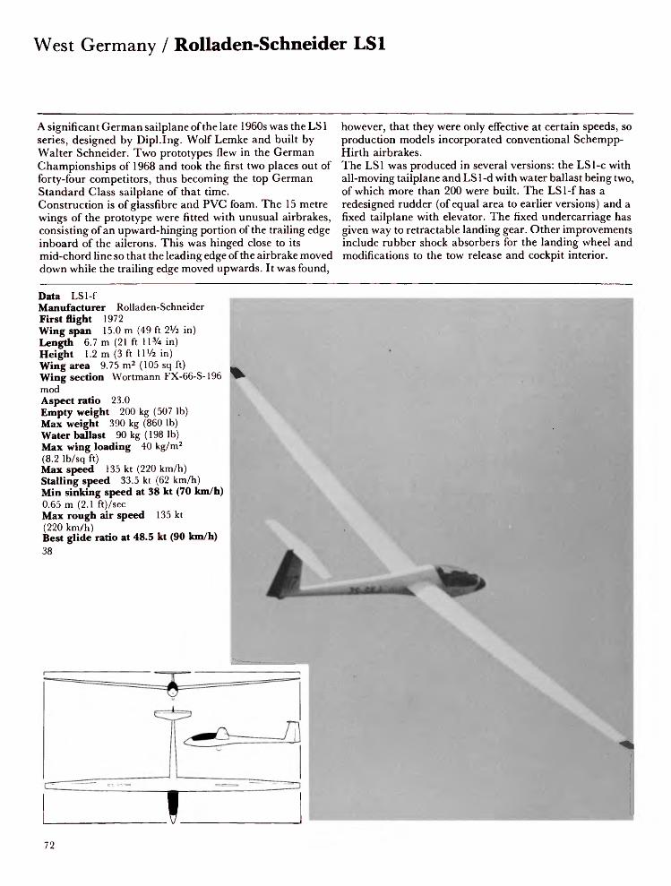
West Germany / Rolladen-Schneider LSI
A significant German sailplane of the late 1960s was the LS1 series, designed by Dipl.Ing. Wolf Lemke and built by Walter Schneider. Two prototypes flew in the German Championships of 1968 and took the first two places out of forty-four competitors, thus becoming the top German Standard Class sailplane of that time. Construction is of glassfibre and PVC foam. The 15 metre wings of the prototype were fitted with unusual airbrakes, consisting of an upward-hinging portion of the trailing edge inboard of the ailerons. This was hinged close to its mid-chord line so that the leading edge of the airbrake moved down while the trailing edge moved upwards. It was found,
however, that they were only effective at certain speeds, so production models incorporated conventional Schempp- Hirth airbrakes.The LSI was produced in several versions: the LSl-c with all-moving tailplane and LS 1-d with water ballast being two, of which more than 200 were built. The LSl-f has a redesigned rudder (of equal area to earlier versions) and a fixed tailplane with elevator. The fixed undercarriage has given way to retractable landing gear. Other improvements include rubber shock absorbers for the landing wheel and modifications to the tow release and cockpit interior.
Data LSl-fManufacturer Rolladen-SchneiderFirst flight 1972Wing span 15.0 m (49 ft 2*/2 in)Length 6.7 m (21 ft 11% in)Height 1.2m (3ft 11 Va in)Wing area 9.75 m2 (105 sq ft)Wing section Wortmann FX-66-S-196modAspect ratio 23.0Empty weight 200 kg (507 Ib)Max weight 390 kg (860 Ib)Water ballast 90 kg (198 Ib)Max wing loading 40 kg/m2(8.2 Ib/sq ft)Max speed 135 kt (220 km/h)Stalling speed 33.5 kt (62 km/h)Min sinking speed at 38 kt (70 km/h)0.65 m (2.1 ft)/secMax rough air speed 135 kt(220 km/h)Best glide ratio at 48.5 kt (90 km/h)38
I72

The championship winning design of the LS1, which may be said to be one of the second generation of glassfibre sailplanes, is almost ten years old; the LS2, which won the 1974 World Championships, never went into quantity production, and now Wolf Lemke and Walter Schneider have designed the LS3, built by Rolladen-Schneider. Design and construction of the LS3 began in 1975 and the aircraft first flew on 4 February 1976 at Egelsbach, Germany. This single-seat high performance 15 metre sailplane has cantilever mid-set wings of glassfibre/foam sandwich construction. One-piece flaperons ran the entire length of the trailing edge but were replaced by conventional
flaps and ailerons in 1979. Airbrakes operate on the upper wing surfaces and there is provision for 120 kg (265 lb) of water ballast.The fuselage, similar to that of the LSl-f, features a flush one-piece hinged canopy and T-tail with fixed tailplane with elevator. Landing gear consists of a monowheel with rubber shock absorber which is located 25 mm forward of the centre of gravity. An innovation is the mechanism which automatically prevents opening of the airbrakes at the incorrect flap setting. The LS3A-17 is a 17m version with detachable wingtips for conversion to a 15m sailplane.
Data LS3AManufacturer Rolladen-SchneiderFirst flight February 1976Wing span 15.0 m (49 ft 2Vi in)Length 6.8 m (22 ft 3% in)Height 1.2m (3ft 11V4 in)Wing area 10.2 m2 (109.8 sq ft)Wing section WortmannAspect ratio 22.0Empty weight 246 kg (542 lb)Max weight 470 kg (1,036 lb)Water ballast 120 kg (265 lb)Max wing loading 46.0 kg/m2 (8.19 Ib/sq ft)Max speed 135 kt (250 km/h)Stalling speed 35 kt (65 km/h)Min sinking speed at 38 kt (70 km/h) 0.55 m (1.8 ft)/secMax rough air speed 135 kt (250 km/h)Best glide ratio at 59 kt (110 km/h) 40
81

West Germany / Scheibe Bergfalke 4
The Bergfalke 4 is a two-seat high-performance sailplane designed by Egon Scheibe and is a development of the 1951 Mii 13E Bergfalke and its improved versions, Bergfalke 2 and 3. Construction of the prototype began in early 1969 with the first flight following a few months later. Because of its excellent performance the Bergfalke 4 can be used for competition flying as well as for training. The low sink rate makes it possible to soar in relatively weak thermals. Great importance has been attached to ease and speed of rigging. The two-piece wings are of wooden construction with a single laminated box spar joined together at the fuselage centre-line with one vertical pin. The wing leading
edge is covered with birch ply with fabric aft of the main spar. Large Schempp-Hirth airbrakes are fitted. The fuselage is of tubular steel construction with a glassfibre nose section; the remainder is fabric covered. The landing gear consists of a large non-retractable monowheel fitted with a brake. The tailplane is wood with a Flettner-type trim tab on the elevator and is located by three spigots and secured by a nut.In 1976, two versions of the Bergfalke 4 were entered for the Sixth German Motor Glider Competition: the twin-engined version and the retractable-engine version, which later put up a world 300 km triangle record.
Data Bergfalke 4Manufacturer ScheibeFirst flight 1969Wing span 17.2 m (56 ft 5 in)Length 8.00 m (26 ft 3 in)Height 1.5 m (4ft 11 in)Wing area 17.5 m2 (188 sq ft)Wing section Wortmann SO2/SO2/1Aspect ratio 16.9Empty weight 300 kg (661 Ib)Max weight 505 kg (1,113 Ib)Water ballast NoneMax wing loading 29.4 kg/m2 (6.02 Ib/sq ft)Max speed 108 kt (200 km/h)Stalling speed 35 kt (65 km/h)Min sinking speed at 40.5 kt (75 km/h) 0.68 m (2.2 ft)/secMax rough air speed 92 kt (170 km/h)Best glide at ratio at 46 kt (85 km/h) 34
74
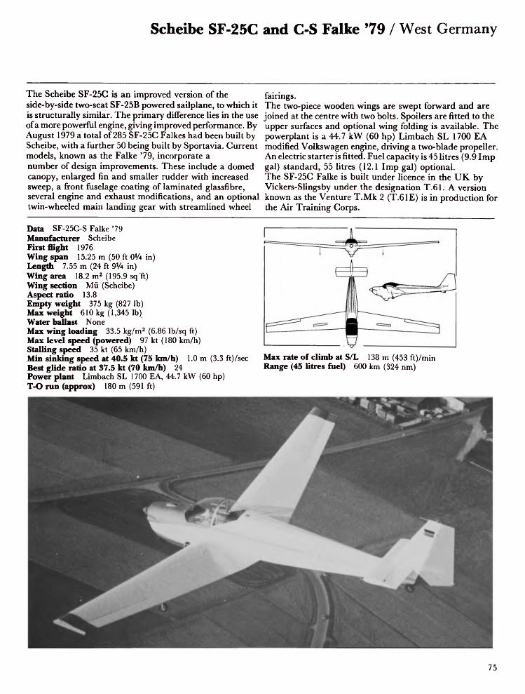
Scheibe SF-25C and C-S Falke '79 / West Germany
The Scheibe SF-25C is an improved version of the side-by-side two-seat SF-25B powered sailplane, to which it is structurally similar. The primary difference lies in the use of a more powerful engine, giving improved performance. By August 1979 a total of 285 SF-25C Falkes had been built by Scheibe, with a further 50 being built by Sportavia. Current models, known as the Falke '79, incorporate a number of design improvements. These include a domed canopy, enlarged fin and smaller rudder with increased sweep, a front fuselage coating of laminated glassfibre, several engine and exhaust modifications, and an optional twin-wheeled main landing gear with streamlined wheel
fairings.The two-piece wooden wings are swept forward and are joined at the centre with two bolts. Spoilers are fitted to the upper surfaces and optional wing folding is available. The powerplant is a 44.7 kW (60 hp) Limbach SL 1700 EA modified Volkswagen engine, driving a two-blade propeller. An electric starter is fitted. Fuel capacity is 45 litres (9.9 Imp gal) standard, 55 litres (12.1 Imp gal) optional. The SF-25C Falke is built under licence in the UK by Vickers-Slingsby under the designation T.61. A version known as the Venture T.Mk 2 (T.61E) is in production for the Air Training Corps.
Data SF-25C-S Falke '79Manufacturer ScheibeFirst flight 1976Wing span 15.25 m (50 ft OV4 in)Length 7.55 m (24 ft 9x/4 in)Wing area 18.2 m2 (195.9 sq Tt)Wing section Mii (Scheibe)Aspect ratio 13.8Empty weight 375 kg (827 Ib)Max weight 610 kg (1,345 Ib)Water ballast NoneMax wing loading 33.5 kg/m2 (6.86 Ib/sq ft)Max level speed (powered) 97 kt (180 km/h)Stalling speed 35 kt (65 km/h)Min sinking speed at 40.5 kt (75 km/h) 1.0 m (3.3 ft)/secBest glide ratio at 37.5 kt (70 km/h) 24Power plant Limbach SL 1700 EA, 44.7 kW (60 hp)T-O run (approx) 180 m (591 ft)
Max rate of climb at S/L 138 m (453 ft)/min Range (45 litres fuel) 600 km (324 nm)
75

West Germany / Scheibe SF-25E Super-Falke
The Scheibe Falke series of motor gliders has proved to be one of the most popular of this class of aircraft. By the end of 1969 some 360 Falkes of types A, B and C had been built by Scheibe, 90 B and C models produced under licence by Sportavia-Putzer, and 30 had been built by Slingsby. At the First German Motor Glider Championships, in June 1970 at Burg Feuerstein, three SF-25B Falkes were among the first five.The SF-25E Super-Falke, which first flew in June 1974, took first place in the advanced two-seater class at the First International Motor Glider Competition. It is a development of the SF-25C and features a wing increased in
span by 2.7 m (8 ft 10V4 in), a feathering propeller and an adjustable engine cooling flap.The fuselage is a fabric-covered welded steel-tube structure with a wider section aft of the wing than on the SF-25C to improve airflow at the wing root, and a larger fairing for the main landing wheel. This wheel is rubber sprung in torsion, and two outrigger wheels supported on nylon legs are fitted to the inner panels of the wing so that the outer panels can be folded for hangarage.
Data SF-25E Super-FalkeManufacturer ScheibeFirst flight 1974Wing span 18.0 m (59 ft OVa in)Length 7.6 m (24 ft 1 l x/4 in)Wing area 17.4 m2 (187.3 sq ft)Wing section Mii (Scheibe)Aspect ratio 17.8Empty weight (approx) 410 kg (904 Ib)Max weight 630 kg (1,389 Ib)Water ballast NoneMax wing loading 35 kg/m2 (7.16 Ib/sq ft)Max speed 97 kt (180 km/h)Stalling speed 37.5 kt (70 km/h)Min sinking speed at 40.5 kt (75 km/h) 0.85 m (2.8 ft)/secBest glide ratio at 46 kt (85 km/h) 30Power plant Limbach SL 1700, 48.5 kW (65 hp)T-O run 150-200 m (490-655 ft)
Rate of climb 144 m (472 ft)/min Range 600 km (324 nm)
76

Scheibe SF-28A Tandem-Falke / West Germany
Egon Scheibe, who has more than forty years of experience in sailplane design, is currently producing the SF-28A tandem two-seat motor glider, which competed in the German Motor Glider Competition in 1977.A distinguishing feature of the aircraft is the positioning of the cockpit above the wings, the front pilot sitting in line with the wing leading edge and the rear pilot over the main spar. It is developed from the Bergfalke and Falke and is offered as an alternative to the SF-25C and SF-25E, both of which have side-by-side seating.The fuselage is a fabric-covered steel tube structure with a conventional wooden tail and large one-piece perspex
canopy. The landing gear comprises non-retractable main wheel, outrigger wheels positioned at mid-wing on nylon legs, and a tail-wheel linked to the rudder control for manoeuvrability on the ground. The single-spar wings are constructed from wood and fabric and incorporate spoilers on the upper surface.The power plant, situated in the nose, is a 48.5 kW (65 hp) Limbach SL 1700 EA modified Volkswagen engine driving a two-blade feathering propeller. The Tandem-Falke is capable of very good soaring performance and in 1976 flown by Peter Ross established the two UK records for motor gliders.
Data SF-28 Tandem FalkeManufacturer ScheibeFirst flight May 1971Wing span 16.3 m (53 ft 5% in)Length 8.1 m (26 ft 6% in)Height 1.55 m (5 ft 1 in)Wing area 18.35 m2 (197.5 sq ft)Wing section Gottingen 533Aspect ratio 14.5Empty weight 400 kg (881 Ib)Max weight 590 kg (1,301 Ib)Water ballast NoneMax wing loading 32.2 kg/m2 (6.59 Ib/sq ft)Max speed 102.5 kt (190 km/h)Stalling speed 33.5 kt (62 km/h)Min sinking speed at 37.5 kt (70 km/h) 0.9 m (3 ft)/secBest glide ratio at 51 kt (95 km/h) 27Power plant Limbach SL 1700 EA1, 48.5 kW (65 hp)
T-O run 180 m (591 ft)Max rate of climb at S/L 126 m (413 ft)/minRange 500 km (270 nm)
77

West Germany / Scheibe SF-30 Club-Spatz
The SF-30 is one of a long series of Scheibe sailplanes and motor gliders. It is a Standard Class sailplane built to comply with the German Club Class which was set up in an attempt to supply simple easy-to-rig robust gliders for use by inexperienced pilots. Design was started in 1973 and the prototype first flew on 20 May 1974. Developed from the SF-27, it has a typical Scheibe welded steel tube fuselage, mostly fabric-covered. The front fuselage is glassfibre-covered and contains a large comfortable cockpit with adjustable seat and rudder pedals. Good visibility is provided by a sideways-hinged blown Plexiglas canopy.
The wings and tail surfaces are of composite glassfibre construction in that the outer surfaces of the wings are completely of glassfibre supported by plastic foam. The only concession to cheapness is in the use of spoilers in place of airbrakes. Spoilers are effective for glide-path control but are unsuitable for cloud flying. The SF-30 does not have the all-flying tail of the SF-27, but the elevators are damped and trimming is achieved by means of an adjustable spring. The landing gear consists of a non-retractable unsprung monowheel with brake, and a sprung tail skid.
Data SF-30 Club-SpatzManufacturer ScheibeFirst flight May 1974Wing span 15.0 m (49 ftLength 6.1 m (20 ft 0 in)Wing area 9.3 m2 (100.1 sq ft)Wing section WortmannAspect ratio 24.0Empty weight 185 kg (408 Ib)Max weight 295 kg (650 Ib)Water ballast NoneMax wing loading 31.7 kg/m2 (6.49 Ib/sq ft)Max speed 114 kt (211 km/h)Stalling speed 35 kt (65 km/h)Min sinking speed at 40.5 kt (75 km/h) 0.59 m (1.9 ft)/secBest glide ratio at 49 kt (91 km/h) 37

Scheibe SF-32 / West Germany
The SF-32 is the successor to the SF-27M, which won the single-seat class at the German Motor Glider competitions in 1970 and 1971. Designed in 1967, the SF-27M is similar in construction to the SF-27, but with an internally strengthened wing and control surfaces and a modified fuselage centre section. The manually-operated winding handle which raises and lowers the retractable engine has been replaced on the SF-32 by an electrical mechanism. The fuselage of the SF-32 consists of a welded steel-tube structure with the nose section covered with a moulded glassfibre shell back to the wing trailing edge. The remainder is fabric covered. The wings, which are built in two parts, are
essentially those of the Neukom Elfe 17. The main spar is aluminium alloy and the covering consists of a 6 mm shell of glassfibre and plywood/foam sandwich. Schempp-Hirth airbrakes are fitted to the upper surfaces. The all-flying tailplane has a geared anti-balance tab which is also operated by the trimmer.The power plant is a 30 kW (40 hp) Rotax 642 flat-twin two-stroke engine driving a two-blade wooden propeller. Mounted on a pylon, the engine is electrically retracted into the fuselage aft of the wing trailing edge beneath flush fitting doors.
Data SF-32Manufacturer ScheibeFirst flight May 1976Wing span 17.0 m (55 ft 9V4 in)Length 7.0 m (22 ft 11V2 in)Height 1.25m (4ft 1V4 in)Wing area 13.3 m2 (143.2 sq ft)Wing section Wortmann FX-61 -163/60-126Aspect ratio 21.73Empty weight 340 kg (750 Ib)Max weight 450 kg (992 Ib)Water ballast NoneMax wing loading 33.8 kg/m2 (6.92 Ib/sq ft)Max speed 119 kt (220 km/h)Stalling speed 36.5 kt (68 km/h)Min sinking speed at 43.5 kt (80 km/h) 0.65 m (2.1 ft)/secBest glide ratio at 48.5 kt (90 km/h) 37Power plant Rotax 642 2-stroke, 30 kW (40 hp)
T-O run 200 m (656 ft) Max rate of climb at S/L Range 300km(162nm)
120m (394ft)/min
79

West Germany / Scheibe SF-33
The single-seat SF-33, new in 1977, was designed by Scheibe as a trainer motor glider to fill the gap in their range between the two-seat SF-25 series and the high-performance single-seat SF-32. It has a conventional light aircraft configuration with broad nose, and cockpit located over the wing covered by a large side-hinged blown canopy giving excellent all-round visibility.The SF-33 is designed specifically to be easy to handle and the manufacturers have kept in mind the need for it to be used by beginners to continue their training up to a high standard of competence. The two-piece wings are constructed of wood with plywood leading edges and wooden
ailerons. The fuselage is a robust steel-tube frame covered with plywood and fabric with a conventional tail unit. The landing gear consists of a fixed main wheel, a steerable tail wheel controlled by the rudder pedals and two detachable outrigger wheels which allow the pilot to operate independently of a launch crew. The gliding performance is claimed to be comparable with that of the Ka 8. The power plant is the four-stroke BMW 900 cc motorcycle engine. Developing about 26 kW (35 hp), it drives a variable-pitch Hoffmann propeller.
Data SF-33Manufacturer ScheibeFirst flight 1977Wing span 15.0 m (49 ft 2Vi in)Length 6.75 m (22 ft 1% in)Wing area 12.5 m2 (134.6 sq ft)Wing section ScheibeAspect ratio 18.0Empty weight 300 kg (661 Ib)Max weight 410 kg (904 Ib)Water ballast NoneMax wing loading 32 kg/m2 (6.55 Ib/sq ft)Max level speed 92 kt (170 km/h)Stalling speed 36 kt (67 km/h)Min sinking speed at 43 kt (80 km/h) 0.85 m (2.8 ft)/secBest glide ratio 28Power plant BMW 900 cc, 26 kW (35 hp)T-O run 150-200 m (492-656 ft)
Rate of climb 150 m (492 ft)/min Range 300 km (162 nm)

Scheibe SF-H34 / West Germany
The Scheibe SF-H34 is a two-seat glider of minimum size which can be used for ab initio and advanced training and cross-country flying. Designed by Dipl Ing Hoffmann, the SF-H34 was Scheibe's first venture into all-glassfibre construction and is designed for a long and useful life as a club trainer. The prototype first flew in October 1978 and the first production machine appeared in late summer 1979. The glassfibre fuselage features a conventional tail unit and a large one-piece canopy, hinged to open sideways and giving excellent all-round visibility for both pupil and instructor. The cockpit incorporates semi-reclining seats with dual controls in tandem. Backrests and rudder pedals are
adjustable in flight. Hooks for aerotowing and winch launching are provided.The two-piece mid-set wing is a single-spar glassfibre structure. In the production version the wing leading edge is at right angles to the fuselage. The airbrakes are fitted to the upper surface of the wings. Easy ground handling has been assured by placing the rear of the two tandem wheels directly below the aircraft's centre of gravity.
Data SF-H34Manufacturer ScheibeFirst flight October 1978Wing span 15.8 m (51 ft 10 in)Length 7.5 m (24 ft 7 in)Height 1.45m (4 ft 9 in)Wing area 14.8 m2 (159.3 sq ft)Wing section Wortmann FX-61-184/FX-60-126Aspect ratio 17.0Empty weight 290 kg (639 Ib)Max weight 490 kg (1,080 Ib)Water ballast NoneMax wing loading 33.2 kg/m2 (6.8 Ib/sq ft)Max speed 135 kt (250 km/h)Stalling speed 35 kt (65 km/h)Min sinking speed at 40 kt (75 km/h) 0.70 m (2.3 ft)/secMax rough air speed 86 kt (160 km/h)Best glide ratio at 52 kt (95 km/h) 35
81

West Germany / Schempp-Hirth Minimoa
In 1935 two of Germany's leading glider pilots, Wolf Hirth and Martin Schempp, founded the firm of sports aircraft builders, Schempp-Hirth, in Goppingen. They designed the Goppingen 3, which they called the Minimoa (miniature Moazagotl), developing it from the 20 metre Moazagotl, and it was built by Dipl.Ing. Wolfgang Hutter and Wolf Hirth. The first Minimoa had cantilever shoulder-set gull wings. Three years were spent on its development and by 1938, with the wings re-positioned at mid-position, weight reduced and a modified aerofoil section, the Minimoa 3B was produced. From July 1935 to 1939 Schempp-Hirth built 110, thirteen being exported to France, Britain, USA, Argentina, South
Africa and Japan. Several are still flying today. The Minimoa is built from wood and fabric. Its gull wings incorporate airbrakes, and large ailerons extending from the bend to the wingtips and protruding from the trailing edges give the sailplane its characteristic shape. The cockpit, roomy for its time, is covered by a one-piece canopy (a rarity in the mid 1930s) hinged sideways. The recessed landing wheel gives a certain amount of streamlining to the fuselage. The Minimoa set many national records and for a time held the world height record of 6,687 m (21,939 ft).
Data MinimoaManufacturer Schempp-HirthFirst flight 1935Wing span 17.0 m (55 ft 9V4 in)Length 7.0 m (22 ft 11V2 in)Wing area 19.0 m2 (204.5 sq ft)Wing section Gottingen 681Aspect ratio 15.2Empty weight 216 kg (476 Ib)Max weight 350 kg (772 Ib)Water ballast NoneMax wing loading 18.42 kg/m2 (3.77 Ib/sq ft)Max speed 119 kt (220 km/h)Stalling speed 32.5 kt (60 km/h)Min sinking speed at 34 kt (63 km/h) 0.65 m (2.1 ft) /secBest glide ratio at 46 kt (85 km/h) 26
82

Schempp-Hirth SHK / West Germany
The SHK is a high performance Open Class sailplane which, in 1965, was the ultimate development of the wooden sailplane. It was the winner of several World and National Championships until it was outclassed by modern glassfibre aircraft. It was developed from the Austria SH, with the co-operation of the Akaflieg Darmstadt. The most outstanding feature of the SHK is its very large V-tail, which is 50% larger than that on the Standard Austria. The wing span is also increased to 17 metres. The longer fuselage makes possible a more comfortable cockpit, which incorporates a seat easily adjustable in flight and adjustable rudder pedals.
The centre portion of the fuselage is a plywood monocoque structure with internal wood stiffening, containing the retractable landing gear and the main wing attachments. The two-piece wings have main spars of birch laminate covered with plywood and fabric. Glassfibre is used for the nose, cockpit section and tail-cone. Schempp-Hirth airbrakes are fitted and a tail brake parachute was added later. The tail unit consists of two mass-balanced all-moving tailplanes with trim tabs.
Data SHKManufacturer Schempp-HirthFirst flight 1965Wing span 17.0 m (55 ft 9% in)Length 6.3 m (20 ft 8 in)Wing area 14.7 m2 (158.3 sq ft)Wing section Eppler 266Aspect ratio 20.2Empty weight 260 kg (573 Ib)Max weight 370 kg (816 Ib)Water ballast NoneMax wing loading 25.2 kg/m2 (5.16 Ib/sq ft)Max speed 108 kt (200 km/h)Stalling speed 34 kt (63 km/h)Min sinking speed at 37.5 kt (70 km/h) 0.6 m (2 ft)/secMax rough air speed 76 kt (140 km/h)Best glide ratio at 48.5 kt (90 km/h) 38

West Germany / Schempp-Hirth Cirrus
After thirty-two years of building sailplanes in which the stressed areas were all-wood, Schempp-Hirth introduced its first glassfibre sailplane, the Cirrus, in January 1967. It was designed and test-flown by Dipl.Ing. Klaus Holighaus. The prototype Cirrus had an all-moving V-tail, but a conventional tail unit, with tailplane mounted part way up the fin, was adopted for all production models. Trimming is by means of spring bias in the elevator system. The cantilever wings use a thick Wortmann section and, unfashionably, do not feature flaps. Rate of descent is controlled by Schempp-Hirth aluminium airbrakes operating on both upper and lower surfaces of the wings, and
by employing the tail brake parachute. The robust flaplesswing saves weight and achieves good stalling characteristicsby comparison with a thinner section of similar span andaspect ratio fitted with flaps.The construction is mainly of glassfibre/foam sandwich butwith a welded steel-tube structure at the centre section of thefuselage, securing wings and landing gear attachments aswell as the flying control system.Production of the Cirrus ceased in favour of the Nimbus 2 inlate 1971, but manufacture has been continued by VTC inYugoslavia.
Data CirrusManufacturer Schempp-HirthFirst flight January 1967Wing span 17.74 m (58 ft 2Vi in)Length 7.20 m (23 ft 7% in)Height 1.56m (5ft 0 in)Wing area 12.6 m2 (135.6 sq ft)Wing section Wortmann FX-66-196/161Aspect ratio 25.0Empty weight 260 kg (573 Ib)Max weight 460 kg (1,014 Ib)Water ballast 98 kg (216 Ib)Max wing loading 36.5 kg/m2 (7.47 Ib/sq ft)Max speed 119 kt (220 km/h)Stalling speed 38.5 kt (62 km/h)Min sinking speed at 39.5 kt (73 km/h) 0.5 m (1.6 ft)/secMax rough air speed 119 kt (220 km/h)Best glide ratio at 46 kt (85 km/h) 44 .
84

Schempp-Hirth Standard Cirrus / West Germany
The Standard Cirrus, designed by Dipl.Ing. Klaus Holighaus, flew for the first time in March 1969. It is a high performance 15 metre version of the Cirrus, but has nothing in common with it in appearance. It has a new fuselage with a T-tail and a roomy cockpit complete with a one-piece hinged canopy. The wing has a new Wortmann aerofoil but, like the Cirrus, no flaps, and the aspect ratio is reduced from 25 to 22.5, providing a good climb rate even with heavy pilots.The large glassfibre Schempp-Hirth airbrakes operate only on the upper surface of the wings, reducing the risk of damage when landing away and keeping the lower surface of
the wing aerodynamically clean. The Standard Cirrus has exceptionally docile and pleasant handling characteristics and has won national competitions all ever the world. In 1975 the Standard Cirrus, designated the '75', was improved by enlarging the fairings at the wing roots, increasing the area of the airbrakes, modifying the nose so that it is similar to that of the Nimbus 2, substituting a new type of easy-to-rig tailplane fitting and repositioning the jettison valves of the wing water tanks to a point behind the landing wheel.
Data Standard Cirrus 75Manufacturer Schempp-HirthFirst flight Early 1975Wing span 15.0 m (49 ft 2% in)Length 6.35 m (20 ft 9% in)Height 1.32m (4ft 4% in)Wing area 10.0 m2 (107.7 sq ft)Wing section Wortmann FXS-02-196 mod.Aspect ratio 22.5Empty weight 215 kg (474 Ib)Max weight 390 kg (860 Ib)Water ballast 80 kg (176 Ib)Max wing loading 39.0 kg/m2(7.98 Ib/sq ft)Max speed 119 kt (220 km/h)Stalling speed 33.5 kt (62 km/h)Min sinking speed at 40.5 kt(75 km/h) 0.6 m (2 ft)/secMax rough air speed 119 kt(220 km/h)Best glide ratio at 48.5 kt (90 km/h)38.5
85

West Germany / Schempp-Hirth Nimbus 2C
The original Nimbus single-seat sailplane was built by Klaus Holighaus in his spare time with the help of his employers, Schempp-Hirth. It has a three-piece wing of 22 m (72 ft 2V4 in) span and an aspect ratio of 30.6. The fuselage is of the Open Cirrus type. It flew for the first time in January 1969 and in the following year won the World Championship at Marfa, USA, flown by the American George Moffat. The Nimbus 2 (photo), which currently holds two world records and has twice won the World Championships, is the production version and first flew in April 1971. It differs from the original Nimbus in several respects. The wing span has been reduced to 20.3 m (66 ft 7% in) and the fuselage is of the
Standard Cirrus type with T-tail. The wing structure is stiffened to eliminate the bending experienced on the original Nimbus wing and is in four sections for ease of rigging and trailing. Nimbus B and C were developed in 1977 and 1978. Type B has a fixed tailplane and elevator. Type C incorporates new brake flaps instead of upper-surface airbrakes and is available either in glassfibre or in carbon fibre, the latter reducing the empty weight by 35 kg (77 Ib). Together with the AS-W 17 and Jantar 2, the Nimbus 2 is generally regarded as being the highest-performance production sailplane flying today.
Data Nimbus 2C (carbon-fibre version)Manufacturer Schempp-HirthFirst flight August 1978Wing span 20.3 m (66 ft 7 L/4 in)Length 7.33 m (24 ft OVi in)Height 1.45 m (4 ft 9 in)Wing area 14.4 m 2 (155 sq ft)Wing section Wortmann FX-67-K-170Aspect ratio 28.6Empty weight 315 kg (694 Ib)Max weight 650 kg (1,433 Ib)Water ballast 250 kg (551 Ib)Max wing loading 45.0 kg/m 2 (9.2 Ib/sq ft)Max speed 146 kt (270 km/h)Stalling speed 32 kt (60 km/h)Min sinking speed at 43 kt (80 km/h) 0.47 m (1.5 ft)/secMax rough air speed 146 kt (270 km/h)Best glide ratio at 56.5 kt (105 km/h) 49
86

Schempp-Hirth Nimbus 2M (Motor Nimbus) / West Germany
The motor glider that attracted most interest at the First International Motor Glider Competition at Burg Feuerstein, West Germany, in June 1974 was the Schempp-Hirth Nimbus 2M, with its completely retractable 37.3 kW (50 hp) Hirth engine, which had been developed under the direction of Klaus Holighaus. The two-cylinder two-stroke engine was originally produced as a power unit for snowmobile racing in Canada.The significance of this sailplane, like that of the 15 metre motor Cirrus (photo), lies in the fact that current top class sailplanes are now available as self-launching aircraft. In each case the weight of the engine is less than that of the
water ballast carried. Raising and lowering the engine is accomplished electrically, using the motor and rack-and- pinion gearing from a Bosch car sunroof installation. The Motor Nimbus is a mid-wing self-launching sailplane of glassfibre construction featuring four-piece wings, flaps, airbrakes, retractable landing gear, all-flying T-tail and engine mounted above the wings and retracting aft under flush doors into the fuselage. It carries 40 kg (88 Ib) of fuel in its wing tanks and requires a 350 m (1,148 ft) run for take-off using the engine.
Data Nimbus 2MManufacturer Schempp-HirthFirst flight June 1974Wing span 20.3 m (66 ft 7% in)Length 7.33 m (24 ft OVi in)Height 1.45 m (4ft 9 in)Wing area 14.4 m2 (155 sq ft)Wing section Wortmann FX-67-K-170Aspect ratio 28.6Empty weight 440 kg (970 Ib)Max weight 580 kg (1,279 Ib)Water ballast NoneMax wing loading 40.28 kg/m2 (8.25 Ib/sq ft)Max speed 135 kt (250 km/h)Stalling speed 37.5 kt (70 km/h)Min sinking speed at 46 kt (85 km/h) 0.54 m (1.8 ft) /secBest glide ratio at 54 kt (100 km/h) 47Power plant Hirth 0.28, 37.3 kW (50 hp)
T-O run 350 m (1,148 ft)Rate of climb 120 m (395 ft)/minRange 500 km (269 nm)
87

West Germany / Schempp-Hirth SH-7 Mini-Nimbus C
One of the most successful of modern sailplanes is the Standard Cirrus, a development of the Cirrus. Schempp- Hirth, in a similar production pattern, has developed a 15 metre version of the Nimbus 2, designated SH-7 Mini-Nimbus. Designed by Klaus Holighaus, the Mini- Nimbus is a 15 metre Unrestricted Class sailplane, with all the features of the Open Class Nimbus 2. The prototype first flew in September 1976.The slim glassfibre fuselage of the Mini-Nimbus, with a pointed nose similar to that of the Nimbus 2, has a one-piece flush canopy with a longitudinally-curved bottom edge for increased stiffness. The mid-set wings feature
camber-changing flaps and very effective glassfibre airbrakes. The flaps, incorporating wing-root fairings, are operated by a knob in the cockpit which gives five positions between —7° and +10°, and will lower the flaps for landing, with airbrakes opening from the upper wing surface. The trim lever is located in the same slot as the flap lever and is positioned so that when the latter is moved to lower the flaps, it operates the tailplane and gives an automatic flap/trim system.The Mini-Nimbus B has a fixed tailplane and elevator, and the Type C is supplied either in glassfibre or with carbon-fibre wings.
Data Mini-Nimbus C (carbon fibre-winged version)Manufacturer Schempp-HirthFirst Flight September 1976Wing span 15.0 m (49 ft 2 l/2 in)Length 6.41 m (21 ft OV2 in)Wing area 9.86 m2 (106.1 sq ft)Wing section Wortmann FX-67-K-150Aspect ratio 23.0Empty weight 215 kg (474 Ib)Max weight 500 kg (1,102 Ib)Water ballast 190 kg (419 Ib)Max wing loading 51.0 kg/nv2 (10.45 Ib/sq ft)Max speed 135 kt (250 km/h)Stalling speed 33 kt (61 km/h)Min sinking speed at 42 kt (78 km/h) 0.53 m (1.74 ft)/secMax rough air speed 135 kt (250 km/h)Best glide ratio at 57 kt (106 km/h) 42

Schempp-Hirth Janus / West Germany
Although single-seat glassfibre sailplanes with flaps and tail brake parachutes have been well established for some years now, there have been few attempts to apply this material and design to the construction of two-seaters. The Janus, therefore, might well be the precursor of a new style of sailplane which could change instruction techniques of the future. Klaus Holighaus began design of the Janus in 1969 and the prototype first flew in the Spring of 1974. Production began in 1975 and 40 had been delivered by February 1977. The glassfibre monocoque fuselage is similar to that of the Nimbus 2 but the cockpit section is new. It incoporates two seats in tandem beneath a hinged one-piece canopy. The
landing wheel is non-retractable and is fitted with a drum brake. There is a small nose wheel. Dual controls enable the Janus to be used for training and it is particularly suitable for cross-country instruction'as it meets the requirements for a high-performance aircraft, complete with flaps and tail brake parachute. Glassfibre/foam sandwich is used for the two-piece mid-set wings, which are swept forward 2° on the leading edge. The camber-changing flaps operate between + 12° and —7°. Schempp-Hirth airbrakes are fitted to the upper surfaces only.In the 1978 version a fixed-incidence tailplane was adopted, replacing the all-moving tailplane of the earlier models.
Data JanusManufacturer Schempp-HirthFirst flight May 1974Wing span 18.2 m (59 ft 8V2 in)Length 8.62 m (28 ft 3V» in)Height 1.45 m (4 ft 9 in)Wing area 16.6 m2 (178.7 sq ft)Wing section Wortmann FX-67-K-170/15Aspect ratio 20.0Empty weight 370 kg (816 Ib)Max weight 620 kg (1,367 Ib)Water ballast NoneMax wing loading 37.4 kg/m2 (7.66 Ib/sq ft)Max speed 119 kt (220 km/h)Stalling speed 36 kt (67 km/h)Min sinking speed at 40.5 kt (75 km/h) 0.61 m (2 ft)/secMax rough air speed 119 kt (220 km/h)Best glide ratio at 51 kt (95 km/h) 39
ZD
89

West Germany / Schleicher Condor
Influenced by the design of the 19m (62.3ft) Fafnir, advised by Alexander Lippisch and supported by Dipl.Ing. Fritz Kramer, in 1931-32 the young Heini Dittmar designed the Condor. Working in his spare time he built this glider in the workshop at Wasserkuppe and entered it for the 1932 Rhon competition, which it won. It aroused general interest and later went into series production.The Condor 1 had high-set gull wings with strengthened leading edges, braced with V-struts. The Condor 2 was developed in 1935 using a new aerofoil section, the outer part of which was thinner, improving the glide angle and rate of sink at higher speeds. This sailplane set a new world distance
record of 504.2 km (272 nm) in 1935 and was the most popular glider of its time in Germany. In February 1934 a sailplane expedition to South America resulted in Dittmar setting a new world height record of 4,350 m (14,272 ft), which until then had stood at 2,560 m (8,399 ft).The Condor 3, built by Schleicher of Poppenhausen, came out in 1938. It featured a longer slimmer fuselage; the cantilever wings were strengthened and incorporated DFS airbrakes. After the Second World War Dittmar developed the two-seat tandem Condor 4, which has essentially the same layout as the Condor 3. It first flew in 1953.
Data Condor 3Manufacturer SchleicherFirst flight 1938Wing span 17.24 m (56 ft 6V» in)Length 7.6 m (24 ft 1 \% in)Wing area 16.2 m2 (174.4 sq ft)Wing section Gottingen 532Aspect ratio 15.0Empty weight 230 kg (507 Ib)Max weight 325 kg (717 Ib)Water ballast NoneMax wing loading 20.06 kg/m2 (4.11 Ib/sq ft)Max speed 97 kt (180 km/h)Stalling speed 27 kt (50 km/h)Min sinking speed 0.6 m (2 ft)/secBest glide ratio 28
90

Schleicher Rhonadler / West Germany
When the Rhonadler (Rhon Eagle) first appeared in 1932, glider pilots were beginning to use thermals to make cross-country flights and were looking for a sailplane with good performance under those conditions. At that time the criterion for a successful flight had become how great a distance could be covered, rather than how long the sailplane could stay airborne. The Rhonadler was the first significant design of Hans Jacobs, who was becoming widely known through his book Workshop Practice for Sailplane and Glider Building.In construction the Rhonadler shows the influence of the Fafnir, but the former is more simplified, having straight
two-piece cantilever wings, tapering to the tips, and large ailerons. The conventional tail unit incorporates a large rudder and all-moving tailplane. The wide fuselage cross section permits a more roomy cockpit than had been the norm previously.The Rhonadler was built by Schleicher in Poppenhausen and was first flown at the Rhon competition of 1932. It proved to have very satisfactory flying qualities and numerous cross-country flights were made in it over the next five years. This sailplane established Hans Jacobs as a successful designer.
Data RhonadlerManufacturer SchleicherFirst flight 1932Wing span 17.4 m (57 ft 1 in)Length 7.2 m (23 ft 7V2 in)Wing area 18.0 m2 (193.8 sq ft)Wing section Gottingen 652Aspect ratio 16.8Empty weight 170 kg (375 Ib)Max weight 250 kg (551 Ib)Water ballast NoneMax wing loading 13.89 kg/m2 (2.84 Ib/sq ft)Max speed 70 kt (130 km/h)Stalling speed 27 kt (50 km/h)Min sinking speed 0.75 m (2.5 ft)/secBest glide ratio 20
91

West Germany / Schleicher Rhonbussard
A year after the successful Rhonadler appeared, in 1933, Hans Jacobs designed the Rhonbussard for the sailplane manufacturer Schleicher. This sailplane, like its big brother the Rhonadler, has two-part cantilever wings which are attached to the top of the fuselage and contain a leading edge torsion box. It features large ailerons operated by push-rods. As on the Rhonadler the wings are secured by two conical bolts, making rigging comparatively quick and easy. The strong oval section fuselage has a short cockpit with protective windscreen. The landing gear includes a main skid and tail skid. This little glider was regarded as a high performance aircraft
in its day and pilots enjoyed flights of 200 to 300 km (108 to 160 nm) in it. Today, like many gliders of the 1930s, the Rhonbussard is valued by such organisations as the Vintage Glider Club, founded in the UK in June 1973 by Christopher Wills and Dr A.E. Slater. Members of this club have rescued, restored and flown many old gliders, and at least two Rhonbussards are known to be flying in Britain today.
Data RhonbussardManufacturer SchleicherFirst flight 1933Wing span 14.3 m (46 ft 11 in)Length 5.8 m (19 ft Q% in)Wing area 14.1 m2 (151.8 sq ft)Wing section Gottingen 535Aspect ratio 14.5Empty weight 150 kg (331 Ib)Max weight 245 kg (540 Ib)Water ballast NoneMax wing loading 17.4 kg/m2 (3.56 Ib/sq ft)Max speed 70 kt (130 km/h)Stalling speed 27 kt (50 km/h)Min sinking speed 0.75 m (2.5 ft)/secBest glide ratio 20
92

Schleicher Ka 6CR / West Germany
The successful Ka 6 series, designed by Rudolf Kaiser and developed by Rudolf Hesse, was produced as the era of plywood-built sailplanes was coming to an end. The Ka 6, which first flew in November 1956, had a wing span of only 14 m (45 ft 11 in). Later, when the regulations governing the Standard Class were published, the wing span was increased to 15 m (49 ft 2*/2 in) and a landing wheel replaced the skid. These sailplanes were designated Ka 6B and Ka 6BR respectively.At the World Championships in Leszno, Poland, in 1958, Rudolf Kaiser was awarded the prize for the best Standard Class sailplane design. A Ka 6 won the Open Class and was
placed third in the Standard Class; it won the Standard Class in the Championships of both 1960 and 1963 in the hands of Heinz Huth of West Germany.Following a modification of the wing root the Ka 6C was created and, with landing wheel, the Ka 6CR. The structure is of plywood and fabric and the slightly forward-swept single-spar wings incorporate Schempp-Hirth airbrakes. Ease of rigging, high performance and reasonable price all made the Ka 6CR a very popular sailplane, and when production ceased in 1968 more than 1,400 had been built and many exported to all parts of the world.
Data Ka 6CRManufacturer SchleicherFirst flight November 1956Wing span 15.0 m (49 ft 2Va in)Length 6.66 m (21 ft 10V4 in)Wing area 12.4 m2 (135.5 sq ft)Wing section NAG A 63618/63615Aspect ratio 18.1Empty weight 190 kg (419 Ib)Max weight 300 kg (661 Ib)Water ballast NoneMax wing loading 24.2 kg/m2 (4.95 Ib/sq ft)Max speed 108 kt (200 km/h)Stalling speed 33.5 kt (62 km/h)Min sinking speed at 36.5 kt (68 km/h) 0.69 m (2.3 ft)/secMax rough air speed 76 kt (140 km/h)Best glide ratio at 43 kt (68 km/h) 29
93

West Germany / Schleicher Ka 6E
The Ka 6E, produced concurrently with the Ka 6CR for about three years, has proved to be one of the most popular Standard Class sailplanes and has numerous national championships to its credit. It is a development of both the Ka 6CR and the Ka 10. The latter was a modified Ka 6CR with an all-moving tailplane positioned about a third of the way up the fin. However, this version never reached full production although one took part in the 1965 World Championships at South Cerney.The Ka 6E wing is basically the same as that of the Ka 6CR but has a modified leading edge profile. Schempp-Hirth airbrakes are incorporated. The tailplane is the same as that
on the Ka 10, being all-moving, but without tabs. Stability and trimming are provided by a single lever which adjusts the spring tension on the control column. The wood semi-monocoque fuselage has a different profile from the Ka 6CR, the cross section area being reduced by 10%. The cockpit has been enlarged by elongating the canopy and nose, while the canopy itself is lowered by three inches. The wing is mounted lower on the fuselage, and these improvements have resulted in better penetration.
Data Ka 6EManufacturer SchleicherFirst flight Spring 1965Wing span 15.0 m (49 ft 2x/z in)Length 6.66 m (21 ft lOVi in)Height 1.6 m (5 ft 3 in)Wing area 12.4 m2 (135.5 sq ft)Wing section NAG A 63618/63615/Joukowsky 12%Aspect ratio 18.1Empty weight 190 kg (419 Ib)Max weight 300 kg (661 Ib)Water ballast NoneMax wing loading 24.2 kg/m2 (4.95 Ib/sq ft)Max speed 108 kt (200 km/h)Stalling speed 32 kt (59 km/h)Min sinking speed at 38 kt (70 km/h) 0.65 m (2.1 ft) /secMax rough air speed 54 kt (100 km/h)Best glide ratio at 43 kt (80 km/h) 34
94

Schleicher Ka 7 / West Germany
Rudolf Kaiser, designer of the Ka 7, realised a boyhood dream when, as a young man, he built his first glider, the 10-metre Ka 1, and later flew it to gain his Silver 'C' badge. In 1952 he joined Alexander Schleicher at Poppenhausen and designed the wooden two-seat Ka 2 and its development, the Ka 2B, which became a very popular trainer in Germany.The aim of the Ka 7 design was to produce a two-seat sailplane which would not only provide basic training but would enable pilots to continue without a break their training for flying the high performance sailplanes of that time.
The Ka 7 is a tandem two-seat aircraft with cantilever high swept-forward single-spar wooden wing incorporating plywood-covered leading edge torsion box and Schempp-Hirth airbrakes fitted above and below each wing. The fuselage consists of a fabric-covered steel tube frame similar to that of the Ka 4.The Ka 2B had set German height records in 1959 and the Ka 7 twice improved on German distance records, and more than ten years after its first appearance set a new German goal flight record for two-seat sailplanes. The Ka 7 was always a popular club glider and is still flying in several clubs today.
Data Ka 7Manufacturer SchleicherFirst flight 1959Wing span 16.0 m (52 ft 5 3/4 in)Length 8.1 m (26 ft 6% in)Wing area 17.5 m2 (188.4 sq ft)Wing section Gottingen 535/549Aspect ratio 14.6Empty weight 280 kg (617 Ib)Max weight 480 kg (1,058 Ib)Water ballast NoneMax wing loading 27.43 kg/m2 (5.62 Ib/sq ft)Max speed 108 kt (200 km/h)Stalling speed 32 kt (60 km/h)Min sinking speed at 38 kt (70 km/h) 0.85 m (2.8 ft)/secMax rough air speed 70 kt (130 km/h)Best glide ratio at 43 kt (80 km/h) 26
95

West Germany / Schleicher Ka 8B
Designed by Rudolf Kaiser, the Ka 8B is a single-seat trainer version of the Ka 7 two-seater. It is derived from the Ka 6 but the structure is similar to that of the Ka 7 and is suitable for amateur construction. It has good flying characteristics and is useful in weak thermal conditions, making it ideal for club use.The Ka 8 is robust, having a welded steel-tube fuselage structure with spruce longerons covered with fabric, and a glassfibre nose cone. A fixed landing wheel with brake is fitted, together with a skid at the nose and a steel spur at the tail. The wings are of single-spar construction with plywood D leading edge and are fabric covered aft of the spar. The
Schempp-Hirth airbrakes are fitted on both upper and lower surfaces of the wings. The tail unit is of wooden construction, plywood covered, and the control surfaces are fabric-covered. Since the prototype first flew in 1957 there have been three versions of the canopy; the original models were fitted with a very small canopy, the second incorporated windows on the sides of the cockpit to admit more light, and the third, on the Ka 8B, is larger. More than 1,100 Ka 8s of all versions have been built.
Data Ka 8BManufacturer SchleicherFirst flight November 1957Wing span 15.0 m (49 ft 2Vi in)Length 7.0 m (22 ft 1 iVz in)Height 1.57 m (5 ft 1% in)Wing area 14.15 m2 (152.3 sq ft)Wing section Gottingen 533/532Aspect ratio 15.9Empty weight 190 kg (419 Ib)Max weight 310 kg (683 Ib)Water ballast NoneMax wing loading 21.9 kg/m2 (4.48 Ib/sq ft)Max speed 108 kt (200 km/h)Stalling speed 29 kt (54 km/h)Min sinking speed at 32.5 kt (60 km/h) 0.65 m (2.1 ft)/secMax rough air speed 70 kt (130 km/h)Best glide ratio at 39.5 kt ^3 km/h) 27
96

Schleicher AS-W 12 / West Germany
The Schleicher AS-W 12 is the production version of the famous D-36 Circe from Akaflieg Darmstadt, which won the 1964 German Nationals. Designed by Gerhard Waibel it is generally conceded to be one of the highest performance production sailplanes in the world. The prototype was first flown on 31 December 1965 by Edgar Kramer, its builder, and since then pilots have achieved many significant flights in it.Constructed of glassfibre/balsa sandwich, it features long thin wings, full-span camber-changing flaps coupled with ailerons, a long slender fuselage, fully reclining seat, large retractable landing wheel and a T tail. It can be intimidating
to handle because it relies solely on an unjettisonable tail parachute for glide-path control when landing and therefore presents a challenge to aspiring competition-minded pilots. In 1969, W. Scott of the USA set a new world goal flight record of 966 km (520 nm), and in 1970, H.W. Grosse of West Germany joined the small group of pilots to achieve 1,000 km (540 nm) flights. A few weeks later he was runner-up in the World Championships in Texas, where five of the first nine Open Class winners from USA, France, West Germany and the UK were flying the AS-W 12. In 1972 Grosse set a world distance record of 1,460.8 km (788 nm) which still stood in late 1977.
Data AS-W 12Manufacturer SchleicherFirst Bight December 1965Wing span 18.3 m (60 ft OVain)Length 7.35 m (24 ft iVa in)Wing area 13.0 m2 (140 sq ft)Wing section Wortmann FX-62-K-131 mod.Aspect ratio 25.8Empty weight 295 kg (650 Ib)Max weight 430 kg (948 Ib)Water ballast NoneMax wing loading 32.0 kg/m2 (6.57 Ib/sq ft)Max speed 108 kt (200 km/h)Stalling speed 35 kt (65 km/h)Min sinking speed at 39 kt (72 km/h) 0.49 m (1.6 ft)/secMax rough air speed 54 kt (100 km/h)Best glide ratio at 51 kt (95 km/h) 47
97

West Germany / Schleicher AS-K 13
In 1965 Rudolf Kaiser continued development of the two-seat Ka 2 and Ka 7, and by introducing many improvements produced the AS-K 13. It is built by Schleicher of mixed materials, including metal, wood and glassfibre. The swept-forward single-spar wings, retaining the basic constructional principles of the Ka 7 design, are repositioned from upper to mid position, allowing space for a large blown side-hinged canopy and making possible a good all-round view for both pilots. Seating comfort is improved by using glassfibre, and a sprung landing wheel is incorporated for a softer touchdown. The fabric-covered steel-tube frame fuselage has its upper
side lined with a plywood shell and the nose is glassfibre. The wings are of plywood, fabric covered and have 6° forward sweep and 5° dihedral. Metal Schempp-Hirth airbrakes are fitted and the ailerons are of diagonally-laid fabric-covered plywood. A Flettner trim tab is built into the elevator. Push-rods are used for aileron and elevator controls, with cables for the rudder.The prototype first flew in July 1966 and some 750 have been completed to date, with production continuing.
Data AS-K 13Manufacturer SchleicherFirst flight July 1966Wing span 16.0 m (52 ft 5% in)Length 8.18 m (26 ft 10 in)Height 1.6m (5ft 3 in)Wing area 17.5 m2 (188.4 sq ft)Wing section Gottingen 535/549Aspect ratio 14.6Empty weight 290 kg (639 Ib)Max weight 480 kg (1,058 Ib)Water ballast NoneMax wing loading (2-seater) 27.4 kg/m2 (5.61 Ib/sq ft)Max speed 108 kt (200 km/h)Stalling speed 33 kt (61 km/h)Min sinking speed at 35 kt (64 km/h) 0.81 m (2.7 ft)/secMax rough air speed 76 kt (140 km/h)Best glide ratio at 48.5 kt (90 km/h) 28
98

Schleicher AS-K 14 / West Germany
To avoid confusion with the well-known AS-W 12, which Schleicher also built, the Ka 12 motor glider was renamed the AS-K 14. It is a single-seat motor glider using a Ka 6E fuselage with the wings repositioned, lowering the wing root, and with the addition of a tall retractable landing wheel, designed to give the propeller adequate ground clearance. The prototype first flew on 25 April 1967. The cantilever wing is a single-spar wood and fabric structure featuring plywood-covered ailerons, and spoilers on the upper surfaces. The cockpit is covered by a one-piece Plexiglas canopy which gives excellent visibility and is hinged to starboard. The fuselage is of conventional
semi-monocoque wood and plywood construction. The 26hp four cylinder two-stroke Hirth engine, started manually,drives a two-blade feathering Hoffmann propeller and issited conventionally in the nose.In the first German motor glider competition, held in 1970,AS-K 14s took second, third and fourth places, and six yearslater at the sixth German motor glider competition the stillpopular AS-K 14s took second and third places.One AS-K 14 has been fitted with an experimental turbojetof 90 kg thrust. The exhaust is routed through the wings andout through slots at the wing tips.
Data AS-K 14Manufacturer SchleicherFirst flight April 1967Wing span 14.3 m (46 ft 11 in)Length 6.6 m (21 ft 7% in)Height 1.6 m (5 ft 3 in)Wing area 12.68 m2 (136.5 sq ft)Wing section NAG A 63-618/615Aspect ratio 16.8Empty weight 245 kg (540 Ib)Max weight 360 kg (794 Ib)Water ballast NoneMax wing loading 28.6 kg/m2 (5.85 Ib/sq ft)Max speed 108 kt (200 km/h)Stalling speed 33.5 kt (62 km/h)Min sinking speed at 39 kt (72 km/h) 0.75 m (2.5 ft)/secBest glide ratio at 44.5 kt (83 km/h) 28Power plant Hirth F10 K19 2-stroke, 19.4 kW (26 hp)
T-Orun 120 m (394 ft)Rate of climb 150 m (492 ft)/min
99
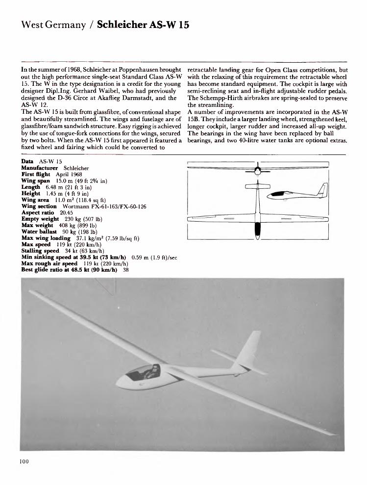
West Germany / Schleicher AS-W 15
In the summer of 1968, Schleicher at Poppenhausen brought out the high performance single-seat Standard Class AS-W 15. The W in the type designation is a credit for the young designer Dipl.Ing. Gerhard Waibel, who had previously designed the D-36 Circe at Akaflieg Darmstadt, and the AS-W 12.The AS-W 15 is built from glassfibre, of conventional shape and beautifully streamlined. The wings and fuselage are of glassfibre/foam sandwich structure. Easy rigging is achieved by the use of tongue-fork connections for the wings, secured by two bolts. When the AS-W 15 first appeared it featured a fixed wheel and fairing which could be converted to
retractable landing gear for Open Class competitions, but with the relaxing of this requirement the retractable wheel has become standard equipment. The cockpit is large with semi-reclining seat and in-flight adjustable rudder pedals. The Schempp-Hirth airbrakes are spring-sealed to preserve the streamlining.A number of improvements are incorporated in the AS-W 15B. They include a larger landing wheel, strengthened keel, longer cockpit, larger rudder and increased all-up weight. The bearings in the wing have been replaced by ball bearings, and two 40-litre water tanks are optional extras.
Data AS-W 15Manufacturer SchleicherFirst flight April 1968Wing span 15.0 m (49 ft 2% in)Length 6.48 m (21 ft 3 in)Height 1.45 m (4 ft 9 in)Wing area 11.0 m2 (118.4 sq ft)Wing section Wortmann FX-61-163/FX-60-126Aspect ratio 20.45Empty weight 230 kg (507 Ib)Max weight 408 kg (899 Ib)Water ballast 90 kg (198 Ib)Max wing loading 37.1 kg/m2 (7.59 Ib/sq ft)Max speed 119 kt (220 km/h)Stalling speed 34 kt (63 km/h)Min sinking speed at 39.5 kt (73 km/h) 0.59 m (1.9 ft)/secMax rough air speed 119 kt (220 km/h)Best glide ratio at 48.5 kt (90 km/h) 38
100
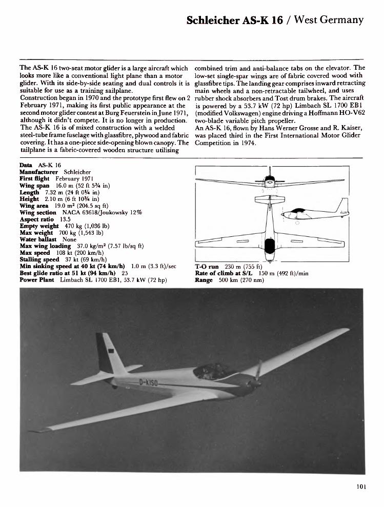
Schleicher AS-K 16 / West Germany
The AS-K 16 two-seat motor glider is a large aircraft which looks more like a conventional light plane than a motor glider. With its side-by-side seating and dual controls it is suitable for use as a training sailplane. Construction began in 1970 and the prototype first flew on 2 February 1971, making its first public appearance at the second motor glider contest at Burg Feuerstein in June 1971, although it didn't compete. It is no longer in production. The AS-K 16 is of mixed construction with a welded steel-tube frame fuselage with glassfibre, plywood and fabric covering. It has a one-piece side-opening blown canopy. The tailplane is a fabric-covered wooden structure utilising
combined trim and anti-balance tabs on the elevator. The low-set single-spar wings are of fabric covered wood with glassfibre tips. The landing gear comprises inward retracting main wheels and a non-retractable tailwheel, and uses rubber shock absorbers and Tost drum brakes. The aircraft is powered by a 53.7 kW (72 hp) Limbach SL 1700 EB1 (modified Volkswagen) engine driving a Hoffmann HO-V62 two-blade variable pitch propeller.An AS-K 16, flown by Hans Werner Grosse and R. Kaiser, was placed third in the First International Motor Glider Competition in 1974.
Data AS-K 16Manufacturer SchleicherFirst flight February 1971Wing span 16.0 m (52 ft 5% in)Length 7.32 m (24 ft 0% in)Height 2.10m (6ft 10% in)Wing area 19.0 m2 (204.5 sq ft)Wing section NAG A 63618/Joukowsky 12%Aspect ratio 13.5Empty weight 470 kg (1,036 Ib)Max weight 700 kg (1,543 Ib)Water ballast NoneMax wing loading 37.0 kg/m2 (7.57 Ib/sq ft)Max speed 108 kt (200 km/h)Stalling speed 37 kt (69 km/h)Min sinking speed at 40 kt (74 km/h) 1.0 m (3.3 ft)/secBest glide ratio at 51 kt (94 km/h) 25Power Plant Limbach SL 1700 EB1, 53.7 kW (72 hp)
T-O run 230 m (755 ft)Rate of climb at S/L 150 m (492 ft)/minRange 500 km (270 nm)
101

West Germany / Schleicher AS-W 17
The AS-W 17, designed by Gerhard Waibel, is a single-seat Open Class sailplane designed with the experience gained from the AS-W 12. The prototype first flew on 17 July 1971 and fifty-two of the type had been built by January 1977. Unlike the AS-W 12's very thin wing the AS-W 17 has a thick modified Wortmann section which enables it to hold up to 100 kg (220 Ib) of water ballast, and is fitted with large Schempp-Hirth aluminium airbrakes on both upper and lower wing surfaces. The camber-changing flaps are integrated with the aileron system. The wing is in four pieces, making rigging and trailing easier. The fuselage consists of a two-skin glassfibre sandwich of a special plastic hexcell
monocoque structure. It features shock-absorbing retractable landing gear and a conventional tail unit. Several world records have been set in AS-W 17s, including a goal flight of 1,231.8 km (655 nm) by W. Grosse of Germany in 1974. An AS-W 17 took second place in the 1972 World Championships at Vrsac, third place at Waikerie in 1974, and first place in Finland in 1976 and in France in 1978. The AS-W 17 is generally considered to be the highest performance sailplane currently in production.
Data AS-W 17Manufacturer SchleicherFirst flight July 1971Wing span 20.0 m (65 ft 7¥2 in)Length 7.55 m (24 ft 9% in)Height 1.86 m (6 ft iVi in)Wing area 14.84 m2 (159.8 sq ft)Wing section Wortmann FX-62-K-131 (modified)Aspect ratio 27Empty weight 405 kg (893 Ib)Max weight 570 kg (1,257 Ib)Water ballast 100 kg (220 Ib)Max wing loading 38.4 kg/m2 (7.86 Ib/sq ft)Max speed 129 kt (240 km/h)Stalling speed 36.5 kt (68 km/h)Min sinking speed at 40.5 kt (75 km/h) 0.5 m (1.6 ft)/secMax rough air speed 129 kt (240 km/h)Best glide ratio at 56.5 kt (105 km/h) 48.5

Schleicher AS-K 18 / West Germany
The AS-K 18, which first flew in October 1974, is a single-seat Club Class sailplane based on the design of the Ka 6E and Ka 8. It combines the simple, rugged construction, docile flying characteristics and ability to soar in weak thermals of the Ka 8 with the cross-country performance of the Ka 6E. The AS-K 18 is designed to progress pilots from first solos to early competition flying. The fuselage consists of a welded steel-tube frame with spruce longerons covered with fabric, with a glassfibre nose section. The cockpit, with its hinged blown Plexiglas canopy, provides excellent visibility and good seating arrangement with plenty of leg room. The aircraft has no front skid as the
fixed landing wheel is located just ahead of the centre of gravity. It incorporates an internal brake and a sprung tail skid is provided. The wing uses the same aerofoil section as the Ka 6E and is of single-spar wooden construction with Schempp-Hirth airbrakes operating on both upper and lower surfaces. The ailerons are plywood covered and the wing trailing edges fabric covered. The tail unit is conventional in configuration, constructed of plywood skin with fabric covered control surfaces and Flettner trim tabs on the elevator.
Data AS-K 18Manufacturer SchleicherFirst flight October 1974Wing span 16.0 m (52 ft 5% in)Length 7.0 m (22 ft 11% in)Height 1.68 m (5 ft 6 in)Wing area 12.99 m2 (139.8 sq ft)Wing section NAG A 63618/Joukowsky 12%Aspect ratio 19.7Empty weight 215 kg (474 Ib)Max weight 335 kg (739 Ib)Water ballast NoneMax wing loading 23.0 kg/m2 (4.71 Ib/sq ft)Max speed 108 kt (200 km/h)Stalling speed 32.5 kt (60 km/h)Min sinking speed at 35 kt (65 km/h) 0.6 m (2 ft)/sec.Max rough air speed 108 kt (200 km/h)Best glide ratio at 40.5 kt (75 km/h) 34
103

West Germany / Schleicher AS-W 19
Even though the AS-W 15 continues to be popular, Schleicher decided to produce a sailplane of similar configuration for more competitive pilots. The AS-W 19 benefits from the new Standard Class and 15 m Unrestricted Class rules (1975), which permit camber-changing flaps and water ballast.Designed by Gerhard Waible, himself a competition pilot, the AS-W 19 is a single-seat Standard Class sailplane with no flaps, while the AS-W 20 is a 15m Unrestricted Class version.The wing is almost identical to that of the AS-W 15, except for the lower aspect ratio and thinner profile, and is
strengthened to accommodate more water ballast. The fuselage was completely redesigned, resulting in a slimmer outline, and the nose profile is similar to that of the AS-W 17. Of glassfibre/honeycomb sandwich construction, the fuselage has a large and roomy cockpit. Unlike the AS-W 15, the 19 has a T-tail with fixed-incidence tailplane and elevator. Landing gear consists of a manually retractable monowheel with disc brake, and a tail skid. With its easy, docile handling, the AS-W 19 has proved a very successful sailplane, winning several national championships and the Standard Class World Championship at Chateauroux in France in 1978.
Data AS-W 19Manufacturer SchleicherFirst flight November 1975Wing span 15.0 m (49 ft 2Va in)Length 6.8 m (22 ft 4 in)Height 1.42 m (4 ft 8 in)Wing area 11.0 m 2 (118.4 sq ft)Wing section Wortmann FX-61-163/60-126Aspect ratio 20.4Empty weight 245 kg (540 Ib)Max weight 454 kg (1,000 Ib)Water ballast 100 kg (220 Ib)Max wing loading 41.27 kg/m 2 (8.4 Ib/sq ft)Max speed 138 kt (255 km/h)Stalling speed 36 kt (67 km/h)Min sinking speed at 39 kt (72 km/h) 0.70 m (2.3 ft)/secMax rough air speed 132 kt (245 km/h)Best glide ratio at 60 kt (110 km/h) 38.5
104

Schleicher AS-W 20 / West Germany
The Schleicher AS-W 20 is a single-seat 15m Unrestricted Class version of the AS-W 19. Both aircraft are generally similar but the AS-W 20 features camber-changing flaps, longer, narrower ailerons, and larger upper-surface airbrakes. The emphasis in performance is on high speed, making the AS-W 20 eminently suitable for competition. The AS-W 20 prototype first flew in January 1977, 14 months after the AS-W 19. The cockpit layout and forward-hinged canopy are identical to those of the AS-W 19, except for an additional lever on the left-hand side of the cockpit to operate the flaps. The flaps move in harmony with the ailerons, though the latter rise to —8° when the flaps are
lowered from +15° to +55° for landing. This also provides good roll control at low speeds. The AS-W 20 has numerous championships to its credit and is proving to be one of the most popular 15 m sailplanes. Summer 1978 saw the introduction of the AS-W 20L, featuring detachable wingtips fitted with ailerons. These changes converted it into an Open Class 16.5 m (54 ft 3 in) sailplane and increased the performance to include a best glide ratio of 45 and a minimum sink rate of 0.55 m (1.8 ft)/sec.
Data AS-W 20Manufacturer SchleicherFirst flight January 1977Wing span 15.0 m (49 ft 2 ¥2 in)Length 6.82 m (22 ft 4V2 in)Height 1.45 m (4ft 9 in)Wing area 10.5 m2 (113.0 sq ft)Wing section Wortmann FX-62K-131Aspect ratio 21.43Empty weight 250 kg (551 Ib)Max weight 454 kg (1,000 Ib)Water ballast 120 kg (265 Ib)Max wing loading 43.2 kg/m2 (8.85 Ib/sq ft)Max speed 146 kt (270 km/h)Stalling speed 35.5 kt (65 km/h)Max rough air speed 97 kt (180 km/h)Min sinking speed at 39 kt (73 km/h) 0.60 m (1.97 ft)/secBest glide ratio at 54 kt (100 km/h) 43
ZD L_
*

West Germany / Schleicher AS-K 21
The AS-K 21, designed by Ing. R. Kaiser, was developed as a successor to the popular AS-K 13 to meet a requirement for a modern two-seater of reasonable cost which would bridge the gap between training gliders and high-performance single-seat sailplanes. The AS-K 21 is Schleicher's first all-glassfibre two-seater. It was originally planned to base the design on an improved AS-K 13 fitted with T-tail and glassfibre wings, but this approach was abandoned in favour of a completely new aircraft. The prototype first flew in December 1978 and production began in 1979. The low, clean fuselage has two semi-reclining seats arranged in tandem under individual canopies, the front unit
opening forward and the rear opening aft. Dual controls are fitted and the T-tail incorporates a fixed tailplane and elevator with spring trim. The landing gear consists of non-retractable tandem wheels - the rear of which is situated behind the centre of gravity and fitted with a drum brake - and a tail skid.The two-piece mid-set wing is a single-spar glassfibre structure without flaps but with large upper-surface airbrakes. The tips are turned down to reduce tip stalling and to keep the wings clean when on the ground.
Data AS-K 21Manufacturer SchleicherFirst flight December 1978Wing span 17.9 m (55 ft 9 in)Length 8.35 m (28 ft 10 in)Height 1.55 m (5 ft 1 in)Wing area 17.95 m 2 (193.2 sq ft)Wing section Wortmann FX-SO2-196/FX-60-126Aspect ratio 16.1Empty weight 350 kg (772 Ib)Max weight 570 kg (1,256 Ib)Water ballast NoneMax wing loading 30.6 kg/m2 (6.271 Ib/sq ft)Max speed 135 kt (250 km/h)Stalling speed 33 kt (62 km/h)Min sinking speed at 36 kt (67 km/h) 0.65 m (2.1 ft) /secMax rough air speed 94 kt (175 km/h)Best glide ratio at 49 kt (90 km/h) 34
106
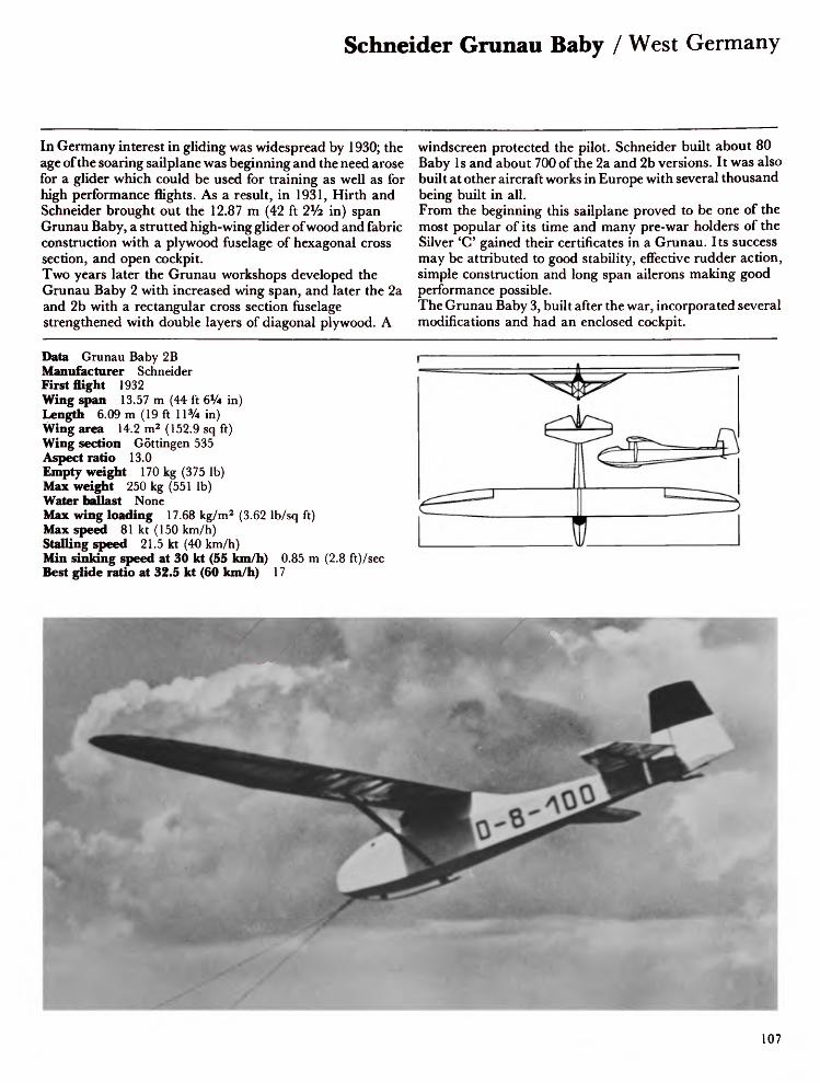
Schneider Grunau Baby / West Germany
In Germany interest in gliding was widespread by 1930; the age of the soaring sailplane was beginning and the need arose for a glider which could be used for training as well as for high performance flights. As a result, in 1931, Hirth and Schneider brought out the 12.87 m (42 ft 2*/2 in) span Grunau Baby, a strutted high-wing glider of wood and fabric construction with a plywood fuselage of hexagonal cross section, and open cockpit.Two years later the Grunau workshops developed the Grunau Baby 2 with increased wing span, and later the 2a and 2b with a rectangular cross section fuselage strengthened with double layers of diagonal plywood. A
windscreen protected the pilot. Schneider built about 80 Baby Is and about 700 of the 2a and 2b versions. It was also built at other aircraft works in Europe with several thousand being built in all.From the beginning this sailplane proved to be one of the most popular of its time and many pre-war holders of the Silver 'C' gained their certificates in a Grunau. Its success may be attributed to good stability, effective rudder action, simple construction and long span ailerons making good performance possible.The Grunau Baby 3, built after the war, incorporated several modifications and had an enclosed cockpit.
Data Grunau Baby 2B Manufacturer Schneider First flight 1932 Wing span 13.57 m (44 ft 6% in) Length 6.09 m (19 ft 11% in) Wing area 14.2 m2 (152.9 sq ft) Wing section Gottingen 535 Aspect ratio 13.0 Empty weight 170 kg (375 Ib) Max weight 250 kg (551 Ib) Water ballast NoneMax wing loading 17.68 kg/m2 (3.62 Ib/sq ft) Max speed 81 kt (150 km/h) Stalling speed 21.5 kt (40 km/h)Min sinking speed at 30 kt (55 km/h) 0.85 m (2.8 ft)/sec- Best glide ratio at 32.5 kt (60 km/h) 17

West Germany / Schweyer Rhonsperber
Inspired by the performance of sailplanes in thermals in the Rhon competition of 1934, Hans Jacobs developed a new aircraft in the Rhon series to take advantage of these weather conditions.The Rhonsperber was developed from the Rhonbussard. Its gull wings were lowered, giving better visibility above and behind and the wing span was increased to 15.2 m (49 ft 1 Ol/2 in). Other improvements included a larger cockpit with the instrument panel at a greater distance from the pilot than had been possible in earlier gliders, enabling him to see the whole panel at a glance. The seat and rudder pedals were adjustable and the control rods and cables were under a fixed
plywood floor. For the first time spoilers were built into the wings and from these Jacobs later developed DFS airbrakes. For three years from 1935 this sailplane held undisputed rank as the leading German glider. About 100 were built by Schweyer at Ludwigshafen.Many memorable long distance flights were made in the Rhonsperber, including two world records. In 1936, Heini Dittmar made the first sailplane flight over the Alps to Italy, and in 1937 Paul Steinig set a new world height record of 5,760m (18,898ft).
Data RhonsperberManufacturer SchweyerFirst flight 1935Wing span 15.3 m (50 ft 2 1/* in)Length 6.05 m (19 ft 10V4 in)Wing area 15.1 m2 (162.6 sq ft)Wing section Gottingen 535Aspect ratio 15.3Empty weight 162 kg (357 Ib)Max weight 255 kg (562 Ib)Water ballast NoneMax wing loading 16.9 kg/m2 (3.46 Ib/sq ft)Max speed 108 kt (200 km/h)Stalling speed 32.5 kt (60 km/h)Min sinking speed 0.72 m (2.4 ft)/secBest glide ratio 20
108

Schweyer Kranich / West Germany
The first true two-seat glider was the Dutch Fokker of 1922. In 1923 Darmstadt produced the Margarete and the Russian Niscegorodez held the two-seater distance record in 1925. But it was not until the 1930s that the real possibilities for training were exploited, and it was with the Mii 10 in 1934 and the Kranich in 1935 that the great era of two-seat dual-control training gliders was initiated. This high-performance tandem two-seat glider was developed from the Rhonsperber. Designed at DPS by Hans Jacobs and built by Ing. Luck, the prototype was completed in the autumn of 1935; the later series aircraft were built at Schweyer in Mannheim. The Kranich, of wood and fabric
construction, has mid-set gull wings fitted with spoilers, but airbrakes were fitted to the strengthened Kranich 2. The plywood fuselage has a very long narrow framed canopy with individual detachable sections. A transparent panel on each root provides downward visibility for the instructor since the rear seat is located behind the wing spar. The landing gear consists of an ash skid and a jettisonable double wheel. A total of 400 Kranichs was built in Germany and many hundreds in Sweden, Czechoslovakia, Poland, Yugoslavia and, until the late 1950s, in Spain. The Kranich held nine world and innumerable national records and in 1952 won the World Championship for two-seaters.
Data KranichManufacturer SchweyerFirst flight Autumn 1935Wing span 18.0 m (59 ft 0% in)Length 7.7 m (25 ft 3Vi in)Wing area 22.7 m2 (244.4 sq ft)Wing section Gottingen 535Aspect ratio 14.3Empty weight 255 kg (562 Ib)Max weight 435 kg (959 Ib)Water ballast NoneMax wing loading 19.16 kg/m2 (3.92 Ib/sq ft)Max speed 116 kt (215 km/h)Stalling speed 37.5 kt (70 km/h)Min sinking speed 0.69 m (2.3 ft)/secBest glide ratio 23.6

West Germany / Sportavia RF-5B Sperber
The Sportavia Company was formed in 1966 to take over from Alpavia the Avion-Flaneur series of powered sailplanes designed by Fournier. In addition to the RF-5B, Sportavia build under licence the SF-25B and SF-25C Falke. The RF-5B is a two-seat motor glider intended for initial training and soaring. It is an improved version of the RF-5 with the wing span increased from 13.75 m (45 ft \% in) to 17.02m (55ft 10 in) and the rear fuselage cut down to reduce side area and improve rearward visibility from the new bulged canopy. The wing is an all-wood single-spar structure with plywood and fabric covering. The outer wings can be folded by a quick-lock system to facilitate hangarage. The
fuselage is an all-wood oval section structure of bulkheads and stringers covered with a plywood skin and the two pilots sit in tandem beneath a one-piece Plexiglas canopy hinged sideways. There is space for 5 kg (11 Ib) of baggage behind the rear seat.Powered by a 50.7 kW (68 hp) Sportavia Limbach SL 1700E Comet engine it has a choice of two types of Hoffmann propeller: a 1.45 m (57 in) diameter two-blade fixed-pitch, or a 1.5 m (59 in) diameter two-blade three-position variable pitch propeller. Fuel is carried in wing-root leading edge metal tanks with a total capacity of 38 litres (8.4 Imp gal).
Data RF-5B SperberManufacturer SportaviaFirst flight May 1971Wing span 17.02 m (55 ft 10 in)Length 7.71 m (25 ft 3V2 in)Height 1.96 m (6ft 5 in)Wing area 19.0 m2 (204.5 sq ft)Wing section NAG A 23015/23012Aspect ratio 15.25Empty weight 470 kg (1,036 Ib)Max weight 680 kg (1,499 Ib)Water ballast NoneMax wing loading 35.7 kg/m2(7.31 Ib/sqft)Max level speed 102 kt (190 km/h)Stalling speed 37 kt (68 km/h)Min sinking speed at 40.5 kt(75 km/h) 0.89 m (2.92 ft)/secBest glide ratio at 53 kt (98 km/h)26Power plant Limbach SL 1700E,50.7 kW (68 hp)T-Orun 187 m (615 ft)Max rate of climb at S/L 180 m(590 ft)/minRange 420 km (227 nm)
110

Start + Plug H 101 Salto / West Germany
Frau Ursula Hanle, a glider pilot herself and widow of Glasflugel's Eugen Hanle, formed a new company to manufacture the H 101 Salto. The design of this single-seat 13 metre sailplane draws extensively on that of their glassfibre sailplane, the H-30, designed by Hiitter, and of the Standard Libelle. The Salto is manufactured so that several components are interchangeable with those of the Libelle.It has a Standard Libelle wing, shortened at the root to give a 13.6 metre span, and is fitted with four flush-fitting trailing edge airbrakes hinged at their mid-point so that half the surface projects above the wing and half below. The
fuselage is all-glassfibre, of robust construction and therefore suitable for club use. The aircraft features a fixed landing wheel with fairing, V-tail and a one-piece canopy which is hinged to open sideways. Although it is a small sailplane the cockpit is surprisingly roomy. The seat back is not adjustable but the rudder pedals are.Salto is the German word for 'loop', and as its name suggests, the Salto is fully stressed for acrobatic as well as normal flying. It first flew in 1970 and by the spring of 1979 some 60 had been built.
Data SaltoManufacturer Start + FlugFirst flight March 1970Wing span 13.6 m (44 ft 7 ¥2 in)Length 5.95 m (19 ft 6V4 in)Height 0.88 m (2 ft 103/4 in)Wing area 8.58 m2 (92.4 sq ft)Wing section Wortmann FX-66-17-Al 1-182Aspect ratio 21.6Empty weight 180 kg (397 Ib)Max weight 310 kg (683 Ib)Water ballast NoneMax wing loading 36.13 kg/m2(7.4 Ib/sq ft)Max speed 135 kt (250 km/h)Stalling speed 35 kt (65 km/h)Min sinking speed at 40.5 kt(75 km/h) 0.6 m (2 ft)/secMax rough air speed 135 kt(250 km/h)Best glide ratio at 48.5 kt (90 km/h)35
11

West Germany / VFW-Fokker FK-3
The FK-3 is an Open Class single-seat high performance sailplane and is intended particularly for weak thermal conditions. Due to its ease of handling it can be flown by pilots of average ability. It was designed by Dipl.Ing. Otto Funk, and the prototype was built by apprentices at VFW (Vereinigte Flugtechnische Werke) at Speyer. The prototype first flew on 24 April 1968 and production started in January 1969.The shoulder-set wing is built with a single metal spar with honeycomb rigid-foam supported skin with ribs of light alloy and plastic foam sandwich, spaced at 140 cm (55 in) intervals, giving the wing an extremely smooth finish.
Differential movement is embodied in the aileron and flap control circuits: the inner flaps operate to +15°, the outer flaps to +13°, while the ailerons move to +11°. Schempp-Hirth airbrakes are fitted and water ballast is carried in two rubber tanks in the wings with the dump valve located in the fuselage aft of the retractable monowheel. The fuselage consists of a steel tube framework covered with a glassfibre shell from the nose to aft of the wing trailing edge and the narrow-diameter tail boom is of light alloy tube bolted to the framework. The tail unit is of similar construction to the wings, with a fabric-covered rudder.
Data FK-3Manufacturer VFW-FokkerFirst flight April 1968Wing span 17.4 m (57 ft 1 in)Length 7.2 m (23 ft 7¥2 in)Wing area 13.8 m2 (148.6 sq ft)Wing section Wortmann FX-62-K-153Aspect ratio 22.0Empty weight 240 kg (529 Ib)Max weight 400 kg (882 Ib)Water ballast 50 kg (110 Ib)Max wing loading 29.0 kg/m2 (5.94 Ib/sq ft)Max speed 146 kt (270 km/h)Stalling speed 27-30 kt (50-55 km/h)Min sinking speed at 34.5 kt (64 km/h) 0.5 m (1.6 ft)/secMax rough air speed 146 kt (270 km/h)Best glide ratio at 47.5 kt (88 km/h) 42
12

HS-2 Mrigasheer / India
The Mrigasheer is a single-seat Standard Class sailplane and is the first to be designed and developed at the Technical Centre by the team of designers and engineers led by Mr K. B. Ganesan, Director of Research and Development. The original version, the HS-1, made its first flight in November 1970. The further developed HS-2 flew for the first time in April 1973, and in the following month was placed second in the first Indian national gliding championships at Kanpur. Based on the aerodynamic design of the first HS-2, a second prototype is under construction. This has trailing-edge slotted flaps in place of airbrakes and glassfibre-reinforced plastic horizontal tail surfaces of different aerofoil section.
The wooden two-spar wings incorporate a plywood leading edge torsion box with plywood covering aft of the main spar. The rear spar carries the hinges of the wooden flaps and ailerons. The fuselage consists of a semi-monocoque wooden structure with plywood covering. The retractable unsprung monowheel is fitted with a conventional drum brake; the rubber-sprung nose-skid and rubber-sprung tailskid complete the landing gear.
Data HS-2 MrigasheerManufacturer Civil Aviation DepartmentFirst flight April 1973Wing span 15.0 m (49 ft 2*/2 in)Length 7.59 m (24 ft 10% in)Height 2.5 m (8 ft 2V2 in)Wing area 11.24 m2 (121.0 sq ft)Wing section Wortmann FX-61-184/163/60-126Aspect ratio 19.85Empty weight 237 kg (522 Ib)Max weight 335 kg (739 Ib)Water ballast NoneMax wing loading 29.54 kg/m2 (6.05 Ib/sq ft)Max speed 115 kt (213 km/h)Min sinking speed 0.58 m (1.9 ft)/secMax rough air speed 80 kt (148 km/h)Best glide ratio 32
13

India / KS-2 Kartik
Though little publicised in the West, India not only has an active Government sponsored gliding movement but also designs and builds her own sailplanes and from time to time holds her own National Championships. This is a country of tremendous potential in gliding achievement with strong thermals, very high cloud bases and unexplored mountains providing excellent wave lift; but there are also great difficulties, not the least of which is the high cost of motoring. The KS-2 Kartik is a locally built single-seat high-performance sailplane developed from the KS—1 Kartik, which was designed by S. Ramamrithram. The improvements to the original design include a slight increase
in fuselage length, a reduction in cockpit height and a tapered wing in place of the original 'double rectangular' wing of the KS-1. It flew for the first time on 4 May 1965, two years after the KS-1. Since then a series of these sailplanes has been built and flown and a number of improvements introduced.The ninth Kartik model (1976) has trailing-edge slotted flaps in place of airbrakes. Construction is conventional, being of wood and fabric, although the nose cap is glassfibre. Landing gear consists of a non-retractable monowheel with drum brake and rubber-sprung nose skid with replaceable steel shoe. The tail skid is sprung with tennis balls.
Data KS-2 KartikManufacturer Civil Aviation DepartmentFirst night May 1965Wing span 15.0 m (49 ft 2Va in)Length 7.37 m (24 ft 2V4 in)Height 2.26 m (7 ft 5 in)Wing area 13.54 m 2 (145.8 sq ft)Wing section NAG A 643618Aspect ratio 16.6Empty weight 210 kg (463 Ib)Max weight 320 kg (705 Ib)Water ballast NoneMax wing loading 23.63 kg/m2 (4.84 Ib/sq ft)Max speed 108 kt (200 km/h)Stalling speed 31 kt (58 km/h)Min sinking speed at 35 kt (65 km/h) 0.6 m (2 ft)/secMax rough air speed 75.5 kt (140 km/h)Best glide ratio at 40.5 kt (75 km/h) 31
14

RG-1 Rohini /India
A pioneer in establishing Indian gliding, Mr S. Ramamrithram, Director General of the Indian Civil Aviation Department, has designed some of the gliders himself. India's economic circumstances having precluded any significant import of foreign gliders, the majority of club aircraft have tended to be of Indian origin, and their construction to be of local materials. Indian gliders have therefore been built exclusively of wood and fabric. The Rohini is the second two-seat glider to be designed and built in India. Designed by S. Ramamrithram, who also designed the first two seater in India, the Ashivini, four prototypes were built between 1961 and 1964 at the
Technical Centre of Civil Aviation. The first prototype flew for the first time on 10 May 1961. The Rohini uses a number of components identical to those on the Ashivini, except that the Ashivini is a tandem two-seater while the Rohini has its seating arranged side-by-side. Construction is of wood and fabric and the high-set wings are strut-braced in a similar way to those of the Slingsby T.21, to which the Rohini bears superficial resemblance.More than 100 Rohinis have been built by Veegal Engines and Engineering Company of Calcutta, and the Hindustan Aeronautics Company at Kanpur.
Data RG-1 Rohini 1Manufacturer Civil Aviation DepartmentFirst flight May 1961Wing span 16.56 m (54 ft 4 in)Length 8.17 m (26 ft 9V2 in)Height 2.33 m (7 ft 7% in)Wing area 20.76 m2 (223.5 sq ft)Wing section NAG A 4418/4412Aspect ratio 13.2Empty weight 274 kg (604 Ib)Max weight 494 kg (1,089 Ib)Water ballast NoneMax wing loading 23.76 kg/m2 (4.86 Ib/sq ft)Max speed 94 kt (174 km/h)Stalling speed 26 kt (48 km/h)Min sinking speed at 33 kt (61 km/h) 0.85 m (2.8 ft)/secMax rough air speed 65 kt (120 km/h)Best glide ratio at 41.5 kt (77 km/h) 22
115

Italy / Aer-Pegaso M-100
Alberto and Piero Morelli designed the 14 m (45 ft 11 in) M-100 in the early 1950s, winning a competition organised by the Italian Aero Club for the best design of a single-seat sailplane. The wing span was later increased to 15 m (49 ft 2V2 in) to meet the Standard class requirements. A total of about 180 was produced both in Italy by Avionautica Rio, and in France under licence by S. A. Carmam where it was known as the M-100 S Mesange (Tomtit). This sailplane is of conventional all-wood construction, part fabric covered with beech main wing spar. The unusual airbrakes comprise three pairs of rotating plates placed above and below each wing. The cantilever all-wood tail unit
incorporates elevator trim tabs and moving surfaces are fabric-covered. The cockpit contains a storage compartment for oxygen and radio equipment behind the seat and is covered by a one-piece Plexiglas canopy hinged sideways. The fuselage is an all-wood semi-monocoque structure with a single towing hook for both aero and winch launching. The landing gear consists of a rubber-sprung nose skid, non-retractable mono wheel with disc brake, and a tail skid.
The M-100 first flew in 1957 and was used for a time as the standard Italian training sailplane. Stressed for normal aerobatics (but not inverted flight) the M-100 S has taken part in both national and international competitions.
Data M-100 SManufacturer Aer-PegasoFirst flight January 1960Wing span 15.0 m (49 ft 2V2 in)Length 6.56 m (21 ft 6 in)Wing area 13.1 m 2 (141 sq ft)Wing section NACA 63618/615Aspect ratio 17.1Empty weight 198 kg (437 Ib)Max weight 315 kg (694 Ib)Water ballast NoneMax wing loading 24.0 kg/m2 (4.91 Ib/sq ft)Max speed 124 kt (230 km/h)Stalling speed 27.5 kt (51 km/h)Min sinking speed at 36 kt (67 km/h) 0.62 m (2 ft)/secMax rough air speed 75.5 kt (140 km/h)Best glide ratio at 41.5 kt (77 km/h) 32
16

Caproni Vizzola Calif A-21S / Italy
This record-breaking two-seat high-performance sailplane, which currently holds no less than four world records for two-seaters, is built by Caproni Vizzola, the oldest Italian aircraft company. Designed by G. Ferrarin and L. Sonzio, the Calif series entered production in 1969 and the A-21 prototype made its maiden flight on 23 November 1970. The original A-21 is no longer being built, its place having been taken by the A-2 IS, which is described below. The low-drag tadpole-shaped fuselage is built of glassfibre with an aluminium alloy strengthened fore section and all-metal tail boom. The all-metal fin and rudder is swept back and the all-moving tailplane is attached to the top of the
fin. The roomy cockpit is fitted with dual controls and is covered by a two-piece canopy.The cantilever mid-set wings have a rectilinear centre section and two trapezoid outer sections. A three-piece, all-metal main spar is supplemented by two auxiliary spars in the centre section and one in each of the outer panels. The wing tips are glassfibre. A special feature of this sailplane is the trailing edge flap/spoiler system, which provides camber changing surfaces between ±8° and acts as an airbrake when deflected to 89° downwards. The landing gear consists of a manually retractable two-wheel undercarriage and fixed tailwheel.
Data Calif A-2 ISManufacturer Caproni VizzolaFirst flight November 1970Wing span 20.38 m (66 ft lOVi in)Length 7.84 m (25 ft 8V2 in)Height 1.61 m (5 ft 3V2 in)Wing area 16.19 m2 (174.3 sq ft)Wing section Wortmann FX-67-K-170/60-126Aspect ratio 25.65Empty weight 436 kg (961 Ib)Max weight 644 kg (1,420 Ib)Water ballast NoneMax wing loading 39.8 kg/m2 (8.15 Ib/sq ft)Max speed 138 kt (255 km/h)Stalling speed 34 kt (63 km/h)Min sinking speed at 46 kt (85 km/h) 0.6 m (2 ft)/secMax rough air speed 138 kt (255 km/h)Best glide ratio at 56.5 kt (105 km/h) 43
117

Italy / CVT M-200
Designed by Alberto and Piero Morelli, the M-200 is the two-seat version of the M-100. The first prototype M-200 was built at the CVT Turin, under a contract from the Aero Club of Italy, and flew for the first time in May 1964. The general layout of the M-100 is maintained, the wing and tail unit having practically the same contour, aerofoil sections and control surfaces, but of different sizes. The main feature of the M-200 is the fuselage, and the cockpit arrangement in particular. Staggered side-by-side seating is adopted; this arrangement allows good visibility for both pilots. Correct balance of the glider is maintained and there is no need for ballast when the aircraft is flown solo.
The fuselage is constructed from plywood with frames and stringers; the one-piece canopy opens sideways. The wing is derived from that of the M-100 by increasing' the span from 15 m (49 ft 2V2 in) to 18.15 m (59 ft GVi in) and the aspect ratio from 17.1 to 19. The wing is a single-spar structure of wood and fabric with leading edge torsion box. The airbrakes consist of four pairs of rotating plates on each wing. The M-200 is easy to fly even for first solo and is stressed for aerobatics.
Data Morelli M-200Manufacturer CVTFirst flight May 1964Wing span 18.15 m (59 ft SVi in)Length 7.6 m (24ft lift in)Wing area 17.5 m2 (188.4 sq ft)Wing section NAG A 63618/615Aspect ratio 19.0Empty weight 345 kg (761 Ib)Max weight 570 kg (1,257 Ib)Water ballast NoneMax wing loading 32.57 kg/m2 (6.67 Ib/sq ft)Max speed 121 kt (225 km/h)Stalling speed 38 kt (70 km/h)Min sinking speed 0.70 m (2.3 ft)/secMax rough air speed 81 kt (150 km/h)Best glide ratio at 53 kt (98 km/h) 32
1 18
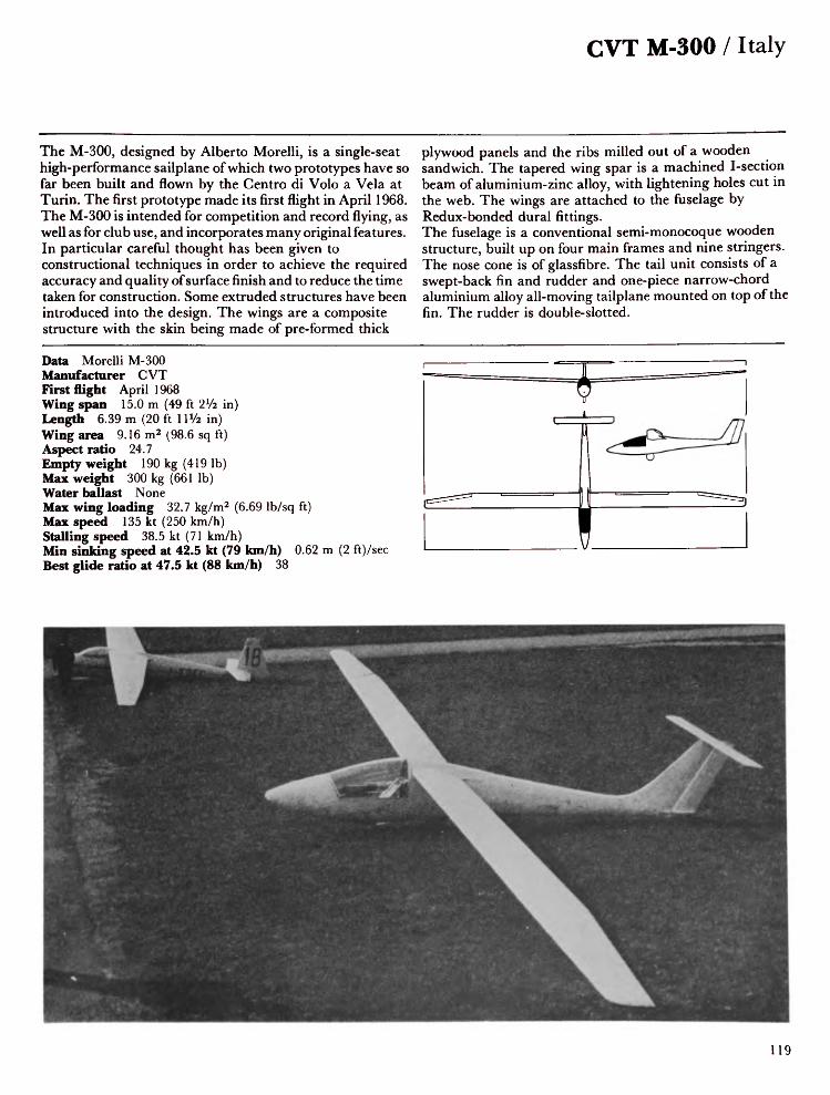
CVT M-300 / Italy
The M-300, designed by Alberto Morelli, is a single-seat high-performance sailplane of which two prototypes have so far been built and flown by the Centre di Volo a Vela at Turin. The first prototype made its first flight in April 1968. The M-300 is intended for competition and record flying, as well as for club use, and incorporates many original features. In particular careful thought has been given to constructional techniques in order to achieve the required accuracy and quality of surface finish and to reduce the time taken for construction. Some extruded structures have been introduced into the design. The wings are a composite structure with the skin being made of pre-formed thick
plywood panels and the ribs milled out of a wooden sandwich. The tapered wing spar is a machined I-section beam of aluminium-zinc alloy, with lightening holes cut in the web. The wings are attached to the fuselage by Redux-bonded dural fittings.The fuselage is a conventional semi-monocoque wooden structure, built up on four main frames and nine stringers. The nose cone is of glassfibre. The tail unit consists of a swept-back fin and rudder and one-piece narrow-chord aluminium alloy all-moving tailplane mounted on top of the fin. The rudder is double-slotted.
Data Morelli M-300Manufacturer CVTFirst flight April 1968Wing span 15.0 m (49 ft 2Vi in)Length 6.39 m (20 ft 1 IVi in)Wing area 9.16 m2 (98.6 sq ft)Aspect ratio 24.7Empty weight 190 kg (419 Ib)Max weight 300 kg (661 Ib)Water ballast NoneMax wing loading 32.7 kg/m2 (6.69 Ib/sq ft)Max speed 135 kt (250 km/h)Stalling speed 38.5 kt (71 km/h)Min sinking speed at 42.5 kt (79 km/h) 0.62 m (2 ft)/secBest glide ratio at 47.5 kt (88 km/h) 38
19

Japan / Nippi NP-100A Albatross
The NP-100A is a side-by-side two-seat ducted-fan motor glider. The modified 44.7 kW (60hp) Kawasaki 748 cc three-cylinder motor cycle engine, driving a four-blade wooden fan of 0.6 m (23.5 in) diameter, is situated in the centre of the fuselage under the wing root. Triple 'venetian-blind' type air intake doors, on each side of the fuselage, are interconnected with the engine starting circuit to prevent the engine from operating when the doors are closed. The 40 litre (8.8 Imp gall) fuel tank is located in the fuselage.The fuselage is an all-metal semi-monocoque structure, with a forward-retracting twin-wheel undercarriage, operating
mechanically with spring assistance. The cockpit is covered by a rearward-hinged framed canopy; dual controls are fitted. The cantilever shoulder-set wings are all-metal with two-piece flaps on each side. The inner flaps have a greater range of movement and can be lowered to 80° for use as airbrakes; the outer flaps move to 48° maximum. Design work began in late 1973 and the prototype flew for the first time on 25 December 1975. Flight testing was carried out during 1976 as a result of which several modifications were made. The first pre-production NP-1OOA was expected to fly in early 1978.
Data NP-1 OOA AlbatrossManufacturer NippiFirst flight December 1975Wing span 18.0 m (59 ft OVi in)Length 8.0 m (26 ft 3 in)Height 2.23 m (7 ft 3% in)Wing area 18.0 m 2 (193.8 sq ft)Wing section Wortmann FX-67-K-170Aspect ratio 18.0Empty weight 420 kg (926 Ib)Max weight 600 kg (1,323 Ib)Water ballast NoneMax wing loading 33.3 kg/m2 (6.82 Ib/sq ft)Max level speed at S/L 86 kt (160 km/h)Stalling speed 35 kt (65 km/h)Min sinking speed at 44.5 kt (83 km/h) 0.8 m (2.6 ft)/secBest glide ratio at 48.5 kt (90 km/h) 30Power plant Kawasaki HZI 748 cc, 44.7 kW (60 hp)
T-O run 365 m (1,198 ft) Max rate of climb at S/L Range 200 km (108 nm)
120m (394ft)/min

Tainan Mita 3 /Japan
Although Japan competes very successfully in many of the world markets this has not included export of her sailplanes. Some single-seat high-performance sailplanes are built but Japanese teams usually fly European-built aircraft in world championships.The Mita 3 is a popular two-seat sailplane designed and built by LADCO until that company relinquished its sailplane section to Tainan, who continued production of the Mita 3 under licence. By January 1976 thirty-seven had been built. This training sailplane features cantilever three-piece shoulder-set wings with a constant chord centre section and tapered outer panels. The wings are of all-wood box-spar
monospar construction with plywood covering and fabric-covered control surfaces. Schempp-Hirth airbrakes are fitted to the upper wing surfaces. The fuselage is a fabric covered steel-tube frame with a glassfibre nose and front section. The tandem seats are covered by a flush-set two-piece canopy hinged to starboard. The wooden tail unit features a large tailplane with fabric covered control surfaces. The landing gear consists of a rubber-sprung non-retractable monowheel with brake, and a tail skid.
Data Mita 3Manufacturer TainanWing span 16.0 m (52 ft 6 in)Length 7.96 m (26 ft iVi in)Height 1.28 m (4 ft 2V2 in)Wing area 15.87 m2 (170.8 sq ft)Wing section NAG A 633618Aspect ratio 16.13Empty weight 300 kg (661 Ib)Max weight 450 kg (992 Ib)Water ballast NoneMax wing loading 28.4 kg/m2 (5.81 Ib/sq ft)Max speed 103 kt (190 km/h)Stalling speed 33.5 kt (62 km/h)Min sinking speed at 40.5 kt (75 km/h) 0.72 m (2.4 ft)/secBest glide ratio at 44 kt (82 km/h) 30
121

Netherlands / Alsema Sagitta
The Sagitta (Arrow), the first Dutch Standard Class single-seat sailplane, was designed and built by Piet Alsema after three years of planning and development. This pleasant looking sailplane features a slender all-wood fuselage with raked fin and rudder, long pointed nose and sliding blown canopy which provides excellent all-round visibility. The wood cantilever tailplane can be folded for trailing. Landing gear comprises a fixed monowheel with brake. The two-piece mid-set wings are all-wood single-spar structures with plywood leading edge torsion box stiffening and 25% fabric covering. The ailerons are the plain wooden type and the airbrakes, which are of a special design, operate
on both upper and lower wing surfaces.The prototype Sagitta made its first flight on 4 July 1960 andthe first production model, designated Sagitta 2, was rolledout on 24 November 1961. Only twenty were built, withsome being exported.The Super Sagitta, first reported in the Spring of 1964, was aproject to evolve a 17 metre version of the Sagitta withincreased wing and tail surface areas.
Data Alsema SagittaManufacturer VliegtuigbouwFirst flight November 1961Wing span 15.0 m (49 ft 2Va in)Length 6.47 m (21 ft 2% in)Wing area 12.0 m2 (129.2 sq ft)Wing section NAG A 63 3618/4412Aspect ratio 18.7Empty weight 217 kg (478 Ib).Max weight 320 kg (705 Ib)Water ballast NoneMax wing loading 26.7 kg/m2 (5.47 Ib/sq ft)Max speed 146 kt (270 km/h)Stalling speed 35.5 kt (66 km/h)Min sinking speed at 42 kt (78 km/h) 0.64 m (2. 1 ft)/secMax rough air speed 108 kt (200 km/h)Best glide ratio at 52.3 kt (97 km/h) 37
122

SZD-8 Jaskolka / Poland
Poland's reputation as source of some of the world's finest high-performance sailplanes had been established before the war and continued in 1951 with the Jaskolka. In the six years from May 1954 to May 1960 this sailplane held no fewer than fifteen world records.Two prototype Jaskolkas were rolled out in 1951, the first in September and the second in December. Three years of development followed before the Jaskolka entered series production. The prototype had a fuselage length of 6.74 m (22 ft iVa in) but in the production series this was increased to 7.42 m (24 ft 4*/4 in). The two-piece cantilever mid-set wings are built of wood
with fabric covering and incorporate Fowler flaps which can be lowered to 12° or 25°, and airbrakes. When the Jaskolka first appeared it incorporated many features not seen before: the moulded two-piece Plexiglas canopy with the aft section sliding back; the recessed handle built into the rear fuselage for ground handling; and the semi-retractable landing wheel.A total of 127 Jaskolkas had been built when production ended in 1961. Many were exported.
Data Jaskolka-ZManufacturer SZDFirst flight 1955Wing span 16.0 m (52 ft 6 in)Length 7.42 m (24 ft 4V4 in)Wing area 13.6 m2 (146.4 sq ft)Wing section NAG A 230 12AAspect ratio 18.8Empty weight 270 kg (595 Ib)Max weight 370 kg (816 Ib)Water ballast 95 kg (209 Ib)Max wing loading 27.2 kg/m2 (5.57 Ib/sq ft)Max speed 135 kt (250 km/h)Stalling speed 27 kt (50 km/h)Min sinking speed at 40 kt (74 km/h) 0.75 m (2.5 ft)/secMax rough air speed 65 kt (120 km/h)Best glide ratio at 44.5 kt (83 km/h) 28.5
123

Poland / SZD-22 Mucha Standard
The Mucha Standard single-seat high-performance sailplane is a development of the famous IS Mucha series which dates back to 1948 and was used in great numbers by Polish gliding groups, achieving several Diamond and record-breaking flights. The SZD-12 Mucha was developed in 1957 and was the forerunner of the Mucha Standard. Designed by R. Grzywacz especially for the 1958 World Championships held in Poland, where it took first place in the Standard Class, flown by Adam Witek, the Mucha Standard has an all-wood structure. The cantilever wings have a single main spar and oblique auxiliary spar and are covered either with plywood (SZD-22B) or fabric
(SZD-22C). The fabric-covered Frise ailerons are both aerodynamically and mass balanced. Airbrakes are fitted inboard of the ailerons.The oval section fuselage is ply wood-covered and the cockpit is covered by a streamlined clamshell Plexiglas canopy. Landing gear consists of short front and rear skids sprung with rubber pads, and a monowheel. More than 240 of the type were built with many of the SZD-22C type being exported.Two further models, D and E, were manufactured, the D type having a modified skid and landing wheel, and the E having a new wing.
Data Mucha StandardManufacturer SZDFirst flight February 1958Wing span 14.98 m (49 ft 1% in)Length 7.0 m (22 ft 11 ¥2 in)Wing area 12.75 fn 2 (137.3 sq ft)Wing section Gottingen 549Aspect ratio 17.6Empty weight 240 kg (529 Ib)Max weight 350 kg (772 Ib)Water ballast NoneMax wing loading 25.6 kg/m2 (5.24 Ib/sq ft)Max speed 135 kt (250 km/h)Stalling speed 32 kt (59 km/h)Min sinking speed at 38.5 kt (71 km/h) 0.73 m (2.4 ft)/secMax rough air speed 108 kt (200 km/h)Best glide ratio at 40.5 kt (75 km/h) 27.8

SZD-9bis Bocian IE / Poland
One of the best known training sailplanes is the two-seat Bocian built by SZD. It is one of the few two-seat gliders stressed for aerobatics, including inverted flight. The prototype was flown for the first time on 11 March 1952 and the first production aircraft in March 1953. Several alterations were made to the tail and to the rudder in particular, and the Bocian C first flew in February 1954 followed by the D in 1958 and finally the E, which first flew on 6 December 1966. By the end of 1976 a total of 593 SZD-9 Bocians had been built.Construction is of wood and fabric. The oval-section fuselage is plywood covered and incorporates two seats in tandem
beneath a long blown Plexiglas canopy. Landing gear consists of a non-retractable monowheel with brake, and front skid. The mid-set wings are swept forward 1° 30' at quarter chord. They consist of a two-spar wooden structure with plywood D-section leading edge and fabric covering. SZD airbrakes are fitted inboard of the slotted ailerons. Between 1955 and 1968 Polish pilots broke many world records in various models of the Bocian, including FranciszekKepka, who set a world record goal flight of 636.6 km (344.1 nm) in 1962. The Bocian currently holds the world height records for two-seaters.
Data Bocian IEManufacturer SZDFirst flight December 1966Wing span 17.8 m (58 ft 4% in)Length 8.21 m (26 ft 1 1% in)Height 1.2m (4ft OV4 in)Wing area 20.0 m2 (215.3 sq ft)Wing section NAG A 43018A/43012AAspect ratio 15.85Empty weight 342 kg (754 Ib)Max weight 540 kg (1,190 Ib)Water ballast NoneMax wing loading 27.0 kg/m2 (5.53 Ib/sq ft)Max speed 108 kt (200 km/h)Stalling speed 32.5 kt (60 km/h)Min sinking speed at 38.5 kt (71 km/h) 0.82 m (2.7 It)/secMax rough air speed 81 kt (150 km/h)Best glide ratio at 43 kt (80 km/h) 26
125

Poland / SZD-19 Zefir 4
The Zefir 4 was the last of the famous wood and fabric built Zefir series which resulted from work done under the leadership of Dipl.Ing. B. Szuba in Poland in 1957-8. The Open Class SZD- 19X Zefir first flew in December 1958 and attracted a great deal of attention at the World Championships in Germany in 1960, where it took second and third places.Of special interest were the slim fuselage, reclining pilot's position, slotted flaps, tail parachute, retractable wheel/tow-hook unit, and the elegant swept-back fin and rudder. The long slim canopy opens by sliding forwards about 8 cm (3 in) and then hinging upwards from the tip of
the nose cone.The Zefir 2 was rolled out in January 1961 and Polish pilots flying this type were placed first and second in the 1963 World Championships in Argentina. Efforts to raise the best glide ratio resulted in the 19 metre Zefir 3 with longer fuselage and full-span flaps. The Zefir 4, developed for the 1968 World Championships, first flew in December 1967. The tail unit had been entirely redesigned without the sweepback of previous models. The wings feature full-span Fowler flaps, the outer sections of which act as ailerons.
Data Zefir 4Manufacturer SZDFirst flight December 1967Wing span 19.0 m (62 ft 4 in)Length 8.0 m (26 ft 3 in)Wing area 15.7 m2 (169 sq ft)Wing section NAG A 66-215-416Aspect ratio 23.0Empty weight 350 kg (772 Ib)Max weight 440 kg (970 Ib)Water ballast NoneMax wing loading 28.0 kg/m2 (5.73 Ib/sq ft)Max speed 129 kt (240 km/h)Stalling speed 36 kt (67 km/h)Min sinking speed at 50 kt (92 km/h) 0.6 m (1.97 ft)/secMax rough air speed 108 kt (200 km/h)Best glide ratio at 51 kt (94 km/h) 42
126

SZD-24 Foka / Poland
Designed by W. Okarmus, the SZD-24 Foka Standard Class high-performance sailplane flew for the first time on 2 May 1960. Its first public appearance at the 1960 World Championships, where it gained third place, caused a great deal of interest because of its radical new design features. Subsequently it was put into series production. Several versions were developed: the SZD-24B Foka 2, which consisted of three pre-production models only, completed early in 1961; the SZD-24C Foka Standard, which was the first major production variant and which first flew in September 1961; the SZD-24-4A Foka. The fuselage consists of a wooden monocoque structure with
the front part in glassfibre. The long transparent canopy opens by sliding forward. The wings are a sparless torsion-box structure with thick plywood stressed skin. SZD metal airbrakes are fitted at 60% chord. The landing gear comprises a long nose skid and a wheel located well behind the centre of gravity.The SZD-32A Foka 5, which first flew on 28 November 1966, won the OSTIV prize for the best Standard class sailplane design. It features a more roomy cockpit and the tailplane is repositioned to the top of the fin. By the time production ended in 1971 a total of 330 Foka series sailplanes had been built, including 200 for export to 17 countries.
Data Foka 4Manufacturer SZDFirst flight February 1962Wing span 15.0 m (49 ft 2Vi in)Length 7.0 m (22 ft 11 ¥2 in)Wing area 12.2 m2 (131.3 sq ft)Wing section NAG A 633618/4415Aspect ratio 18.5Empty weight 245 kg (540 Ib)Max weight 386 kg (851 Ib)Water ballast NoneMax wing loading 31.64 kg/m2 (6.48 Ib/sq ft)Max speed 140 kt (260 km/h)Stalling speed 33.5 kt (62 km/h)Min sinking speed at 43 kt (79 km/h) 0.7 m (2.3 ft)/secMax rough air speed 86 kt (160 km/h)Best glide ratio at 51 kt (95 km/h) 34
127

Poland / SZD-30 Pirat C
The single-seat Pirat was designed by Jerzy Smielkiewicz as a multi-purpose sailplane capable of fulfilling the needs of every area from training to competition flying and is cleared for cloud flying and basic aerobatics. The prototype flew for the first time on 19 May 1966 and production started in 1967; 1,210 had been completed by the end of 1977. The high-set wing is in three parts: a plywood-covered multi-spar centre section, and tapered outer panels of single-spar torsion box construction. The ailerons are mass-balanced and double-plate airbrakes are situated on the centre section and operate on both upper and lower surfaces. The fuselage consists of a plywood monocoque
structure with a glassfibre nose section and cockpit floor. The cockpit is covered by a sideways hinged blown canopy and incorporates adjustable back rest and rudder pedals. Landing gear consists of a front skid with shock absorber and a non-retractable monowheel. The T-tail is all-wood and includes a tab on the trailing edge of the elevator. The Pirat C, which first flew in January 1978, features a more roomy cockpit with a larger canopy. The landing wheel has been moved forward and the nose skid removed.
Data Pirat CManufacturer SZDFirst flight January 1978Wing span 15.0 m (49 ft 2 x/2 in)Length 6.92 m (22 ft 8 in)Height 0.96 m (3 ft 1 3A in)Wing area 13.8 m 2 (148.6 sq ft)Wing section Wortmann FX-61-168/60-1261Aspect ratio 16.3Empty weight 255 kg (562 lb)Max weight 370 kg (816 lb)Water ballast NoneMax wing loading 26.8 kg/m 2 (5.49 Ib/sq ft)Max speed 135 kt (250 km/h)Stalling speed 32.5 kt (60 km/h)Min sinking speed at 40 kt (74 km/h) 0.7 m (2.3 ft)/secMax rough air speed 77 kt (145 km/h)Best glide ratio at 45 kt (84 km/h) 34
128

SZD-36A Cobra 15 / Poland
The SZD-36 Cobra 15 is a single-seat Standard Class high-performance sailplane designed by Dipl. Ing. Wladislaw Okarmus. Design was started in October 1968 and the prototype Cobra 15 flew for the first time on 30 December 1969. In the 1970 World Championships at Marfa, Texas, Polish pilots Wroblewski and Kepka won second and third places in the Standard Class in Cobra 15s, and a Cobra 17 was placed fifth in the Open Class. The cantilever shoulder-set wings are of single-spar wooden construction with heavy moulded plywood stressed skin covered with glassfibre. The plain ailerons are of plywood/polystyrene foam sandwich construction and are
mass-balanced. SZD type metal/glassfibre airbrakes are fitted above and below each wing surface. The 17 metre Open Class Cobra has provision for water ballast in the wings.The fuselage is an oval section all-wood semi-monocoque structure, ply covered at the rear and glassfibre covered at the front. The one-piece blown canopy slides forward to open. Landing gear consists of a manually retractable monowheel and a tailskid. The all-moving T-tail has the swept back fin and rudder characteristic of the series and later models of the Foka and is fitted with a spring trimmer and geared tab.
Data Cobra 15Manufacturer SZDFirst flight December 1969Wing span 15.0 m (49 ft 21/! in)Length 7.05 m (23 ft iVa in)Height 1.59 m (5 ft 2% in)Wing area 11.6 m2 (124.9 sq ft)Wing section Wortmann FX-61 -168/60-1261Aspect ratio 19.4Empty weight 257 kg (567 Ib)Max weight 385 kg (849 Ib)Water ballast NoneMax wing loading 33.2 kg/m2 (6.8 Ib/sq ft)Max speed 135 kt (250 km/h)Stalling speed 36 kt (67 km/h)Min sinking speed at 39.5 kt (73 km/h) 0.6 m (1.97 ft)/secMax rough air speed 91.5 kt (170 km/h)Best glide ratio at 51.5 kt (96 km/h) 38
129

Poland / SZD-40X Halny
First flown on 23 December 1972 by Dipl. Ing. Z. Bylock of the Experimental Institute at Bielskobiala, the two-seat high-performance SZD-40X Halny was designed by W. Okarmus and built as a research sailplane to establish the efficiency of a new wing section. This is a 20-metre adaptation of the Zefir 4 wing, which gave excellent performance at high speeds but was less efficient when thermalling in weak lift.The cantilever shoulder-set wing is a sparless glassfibre/wood box structure with a 4° forward sweep at quarter chord and fittings of stainless steel. It features hingeless flaps and slotless ailerons operated by pushrods.
SZD-type double-plate metal airbrakes, positioned at 60% chord, operate both above and below each wing surface. The fuselage has an all-plastic monocoque front portion, steel tube frame centre portion and metal tube monocoque rear portion. The two tandem seats are covered by a one-piece canopy; the controls and instrument panel are fitted to the rear cockpit only. The T-tail is glassfibre and features spring trimming. The landing gear comprises a retractable monowheel with shoe brake and a fixed tail wheel.
Data HalnyManufacturer SZDFirst flight December 1972Wing span 20.0 m (65 ft 7 x/2 in)Length 8.75 m (28 ft 8¥2 in)Height 1.8 m (5 ft 11 in)Wing area 16.11 m2 (173.4 sq ft)Wing section NN-11MAspect ratio 24.66Empty weight 410 kg (904 Ib)Max weight 596 kg (1,314 Ib)Water ballast NoneMax wing loading 36.9 kg/m2 (7.55 Ib/sq ft)Max speed 130 kt (240 km/h)Stalling speed 35 kt (65 km/h)Min sinking speed at 40.5 kt (75 km/h) 0.55 m (1.8 ft)/secBest glide ratio at 54 kt (100 km/h) 43
30

SZD-48 Standard Jantar 2 / Poland
Designed by Adam Kurbiel, the Jantar series was the first Polish excursion into all-glassfibre sailplanes. The SZD-38 Jantar made its first public appearance at the 1972 World Championships at Vrsac, where it gained second place and won the OSTIV cup for the best 19-metre design. In 1973 it broke seven Polish national records. Originally there were two versions of the Jantar: the SZD-38A Open Class Jantar and the SZD-41 Jantar Standard. These have been superseded by the SZD-42 and SZD-48 respectively. The cantilever shoulder-set wings comprise a single-spar ribless structure with a foam-filled glassfibre/epoxy resin sandwich skin. The wings are flapless and DFS-type glassfibre
airbrakes are fitted above and below each wing. There is provision for 150 kg (330 Ib) of water ballast in the leading edges. The fuselage consists of an all-glassfibre/epoxy resin shell structure; the centre portion has a steel tube frame coupling together the wings, fuselage and landing gear. The pilot sits in a semi-reclining seat under a two-piece canopy, of which the front section is fixed and the rear section is hinged aft. Landing gear consists of a manually-retractable monowheel with disc brake and a fixed tailwheel.
Data Jantar Standard 2Manufacturer SZDFirst flight December 1977Wing span 15.0 m (49 ft 2Vi in)Length 6.71 m (22 ft 8V2 in)Wing area 10.66 m2 (114.8 sq ft)Wing section NN-8Aspect ratio 21.1Empty weight 247 kg (545 Ib)Max weight 520 kg (1,146 Ib)Water ballast 150 kg (330 Ib)Max wing loading 41.27 kg/m2 (8.45 Ib/sq ft)Max speed 167 kt (310 km/h)Stalling speed 39 kt (72 km/h)Min sinking speed at 39.4 kt (73 km/h) 0.65 m (2.0 ft)/secMax rough air speed 86.5 kt (160 km/h)Best glide ratio at 70 kt (130 km/h) 40
131

Poland / SZD-42 Jantar 2B
This high-performance single-seat Open Class sailplane was developed by Dipl. Ing. Kurbiel from the SZD-38A Jantar 1. It flew for the first time on 2 February 1976. The first two examples were flown by the Polish team in the 1976 World Championships, where they gained second and third places in the Open Class.The Jantar 2 is of all-glassfibre construction with wings of 20.5 m (67 ft 3 in) span built in four sections for ease of rigging and trailing. The single-spar wings are of ribless construction with foam filled glassfibre/epoxy resin sandwich skin incorporating multi-hinged ailerons and hingeless trailing-edge flaps hung from the upper surfaces.
DFS-type metal airbrakes operate on both upper and lowerwing surfaces.The fuselage is an all-glassfibre/epoxy resin shell structure,the centre portion of which has a steel tube frame whichcouples the wings, fuselage and landing gear.The most notable difference between the Jantar 2 and othermodels in the Jantar series lies in the tail unit, which has beenchanged from the T-tail arrangement to a conventionalconfiguration comprising stabiliser and elevator.Accommodation is the same as that for the Jantar Standard.
Data Jantar 2BManufacturer SZDFirst flight February 1976Wing span 20.15 m (66 ft \ l/4 in)Length 7.11 m (23 ft 4 in)Height 1.56 m (5 ft 1 ¥2 in)Wing area 14.25 m 2 (153.4 sq ft)Wing section Wortmann FX-67-K-170/150Aspect ratio 29.2Empty weight 355 kg (783 Ib)Max weight 645 kg (1,422 Ib)Water ballast 170 kg (375 Ib)Max wing loading 45.3 kg/m2 (9.28 Ib/sq ft)Max speed 151 kt (280 km/h)Stalling speed 35 kt (65 km/h)Min sinking speed at 40.5 kt (75 km/h) 0.45 m (1.48 ft)/secMax rough air speed 108 kt (200 km/h)Best glide ratio at 57 kt (105 km/h) 48
32

SZD-45A Ogar / Poland
The SZD-45A Ogar (Greyhound) is a two-seat motor glider for ab initio and advanced training and cross-country flying. Designed by Dipl. Ing. Tadeusz Labuc the Ogar made its first flight on 29 May 1973.Of unusual appearance this sailplane has a fuselage of the pod and boom type. The main nacelle structure comprises a glassfibre/epoxy resin shell on two strong wooden frames which carry the wings, engine mounting, fuel tank and the tubular duralumin boom which supports the cantilever T-tail. The wing is a single-spar wooden structure with a moulded plywood stressed skin covered with glassfibre. The slotless ailerons are of glassfibre sandwich construction and
are controlled by pushrods. Airbrakes are fitted above and below each wing. Landing gear consists of a semi-retractable monowheel with shock absorber and disc brake and fully castoring tail wheel.The two seats are arranged side-by-side beneath a two-piece upward-hinged canopy. Dual controls are fitted as standard. The power plant is a 50.7 kW (68 hp) Limbach SL 1700 EC four-cylinder engine, mounted behind the cabin, driving a two-blade Hoffmann pusher propeller.
Data OgarManufacturer SZDFirst flight May 1973Wing span 17.53 m (57 ft 6V4 in)Length 7.95 m (26 ft 1 in)Height 1.72m (5ft 7% in)Wing area 19.1 m2 (205.6 sq ft)Wing section Wortmann FX-61 -168/1261Aspect ratio 16.2Empty weight 470 kg (1,036 Ib)Max weight 700 kg (1,543 Ib)Water ballast NoneMax wing loading 36.6 kg/m2 (7.49 Ib/sq ft)Max level speed at S/L 97 kt (180 km/h)Stalling speed 37 kt (68 km/h)Min sinking speed at 39 kt (72 km/h) 0.96 m (3. 15 ft)/secBest glide ratio at 54 kt (100 km/h) 27.5Power plant Limbach SL 1700 EC, 50.7 kW (68 hp)
T-O run 200 m (656 ft) Max rate of climb at S/L Range 550 km (296 nm)
168m (551 ft)/min
133

Poland / SZD-50 Puchacz 2
Using experience gained in the design of the SZD-50 Dromader 1, which flew in 1976, Dipl.Ing. Adam Meus has developed the Puchacz as a successor to the well known Bocian. The Puchacz 2 is a two-seat high-performance training sailplane designed to provide easy pilot conversion to modern sailplanes.The Puchacz is of conventional glassfibre construction, with wings and landing gear fitting into a central wooden frame. The mid-set, forward-swept wings incorporate airbrakes on their top and bottom surfaces. The conventional tail unit has a hinged elevator and fabric-covered rudder. Two towing hooks are provided, one in the nose for aerotowing and the
other at the centre of gravity for winch launching. The roomy cockpit incorporates two seats in tandem beneath a one-piece, side-hinged canopy. Dual controls and front-seat instrumentation are fitted; the instruments are easily visible from the rear seat, which can be moved fore and aft. The rudder pedals are adjustable in flight. The landing gear consists of a non-retractable mainwheel situated behind the centre of gravity and fitted with a shock-absorber and disc brake, and a small fixed nosewheel. The tail skid can be replaced by a tailwheel.
Data Puchacz 2Manufacturer SZDFirst flight December 1977Wing span 16.67 m (54 ft 8 in)Length 8.38 m (29 ft 10 in)Height 1.92 m (6ft 10V2 in)Wing area 18.16 m2 ((195.5 sq ft)Wing section WortmannAspect ratio 15.3Empty weight 331 kg (730 Ib)Max weight 550 kg (1,216 Ib)Water ballast NoneMax wing loading 30.3 kg/m2 (6.2 Ib/sq ft)Max speed 119 kt (220 km/h)Stalling speed 60 kt (110 km/h)Min sinking speed at 40 kt (75 km/h) 0.7 m (2.3 ft)/secMax rough air speed 81 kt (150 km/h)Best glide ratio at 52 kt (96 km/h) 30
134

ICA-Brasov IS-28B2 / Romania
The IS-28B2 is an improved version of the 15-metre IS-28, the two-seat high-performance sailplane designed by Dipl. Ing. losif Silimon and his team, from which it differs primarily in having 17-metre span all-metal wings, a longer and more slender fuselage and reduced wing and tailplane dihedral. The original IS-28, which first flew in August 1970, had a glide ratio of 25 and minimum sink speed of 0.85 m/sec (2.79 ft/sec).The current production B2 version is of all-metal construction. The mid-set wings are attached to the fuselage by two adjustable tapered bolts at the leading edge and two fixed tapered bolts at the trailing edge. Schempp-Hirth
metal airbrakes are mounted above and below each wing surface. The ailerons and camber-changing flaps, which operate between +15° and — 11°, are fabric covered except for the leading edges. The fuselage is an all-metal semi-monocoque structure of oval cross section. Seating for two persons is arranged in tandem under a one-piece Plexiglas canopy which hinges sideways. The folding cantilever T-tail is similar to that of the IS-28 but with single-spar fin. Landing gear consists of a semi-retractable monowheel with shock absorber and disc brake, and a sprung tailskid.
Data IS-28B2Manufacturer ICA-BrasovFirst flight April 1973Wing span 17.0 m (55 ft 9V» in)Length 8.17 m (26 ft 9Va in)Height 1.8 m (5ft 103A in)Wing area 18.24 m2 (196.4 sq ft)Wing section Wortmann FX-61 -163/60-126Aspect ratio 15.8Empty weight 330 kg (728 Ib)Max weight 590 kg (1,301 Ib)Water ballast NoneMax wing loading 32.34 kg/m2 (6.62 Ib/sq ft)Max speed 144 kt (266 km/h)Stalling speed (two-seat) 39 kt (72 km/h)Min sinking speed at 39 kt (72 km/h) 0.69 m (2.26 ft)/secMax rough air speed 89 kt (136 km/h)Best glide ratio at 54 kt (100 km/h) 34
135

Romania / ICA-Brasov IS-28M2
Designed to Romanian civil airworthiness regulations and complying with OSTIV requirements, the IS-28M2 is of interest both to the gliding and the power flying fraternities. An all-metal motor glider with T-tail, the prototype flew for the first time on 26 June 1976 and made its international public debut at the Farnborough International air show in September.The cantilever low-set wings are of mainly metal construction and are swept forward 2° 30' at quarter chord. The flaps can be set to a negative position to aid high-speed flying between thermals; all-metal Hiitter airbrakes are fitted to the upper wing surfaces. The fuselage is a
conventional structure built in three parts: an oval front section built up on two longerons and cross frames; an aluminium alloy monocoque centre portion; and a rear portion of aluminium alloy frames and skin. The broad cockpit contains side-by-side seating and dual controls, including two throttles and two airbrake levers. The landing gear consists of a semi-retractable two-wheel main gear, mounted at the inboard ends of the wings and integral with the fuselage, and incorporating shock absorption and brakes, and a steerable tailwheel. The power plant is a Limbach SL 1700 E1 driving a Hoffman two-blade variable-pitch fully feathering propeller.
Data IS-28M2Manufacturer ICA-BrasovFirst flight June 1976Wing span 17.0 m (55 ft 9Vi in)Length 7.5 m (24 ft 7% in)Height 2.15m (7ft 0% ft)Wing area 18.24 m2 (196.4 sq ft)Wing section Wortmann FX-61-163/60-126Aspect ratio 15.8Empty weight 530 kg (1,168 Ib)Max weight 745 kg (1,642 Ib)Water ballast NoneMax wing loading 40.84 kg/m2 (8.36 Ib/sq ft)Max level speed 108 kt (200 km/h)Stalling speed 35 kt (65 km/h)Min sinking speed at 43 kt (80 km/h) 0.87 m (2.85 ft)/secBest glide ratio at 54 kt (100 km/h) 29Power plant Limbach SL 1700 El, 50.7 kW (68 hp)
T-O run 160 m (525 ft) Max rate of climb at S/L Range 450 km (243 nm)
186 m (610ft)/min
136
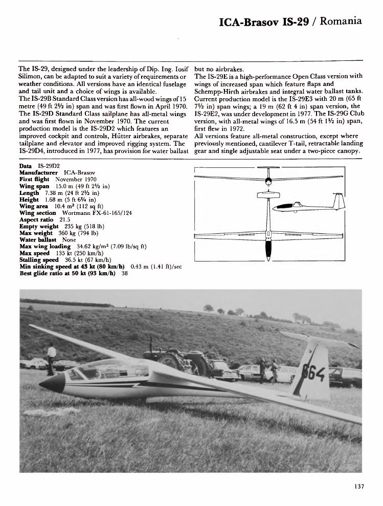
ICA-Brasov IS-29 / Romania
The IS-29, designed under the leadership of Dip. Ing. losif Silimon, can be adapted to suit a variety of requirements or weather conditions. All versions have an identical fuselage and tail unit and a choice of wings is available. The IS-29B Standard Class version has all-wood wings of 15 metre (49 ft 2V2 in) span and was first flown in April 1970. The IS-29D Standard Class sailplane has all-metal wings and was first flown in November 1970. The current production model is the IS-29D2 which features an improved cockpit and controls, Hutter airbrakes, separate tailplane and elevator and improved rigging system. The IS-29D4, introduced in 1977, has provision for water ballast
but no airbrakes.The IS-29E is a high-performance Open Class version with wings of increased span which feature flaps and Schempp-Hirth airbrakes and integral water ballast tanks. Current production model is the IS-29E3 with 20 m (65 ft 7 J/2 in) span wings; a 19 m (62 ft 4 in) span version, the IS-29E2, was under development in 1977. The IS-29G Club version, with all-metal wings of 16.5 m (54 ft \Vz in) span, first flew in 1972.All versions feature all-metal construction, except where previously mentioned, cantilever T-tail, retractable landing gear and single adjustable seat under a two-piece canopy.
Data IS-29D2 Manufacturer ICA-Brasov First flight November 1970 Wing span 15.0 m (49 ft 2Vi in) Length 7.38 m (24 ft 2Vi in) Height 1.68 m (5 ft 6% in) Wing area 10.4 m2 (112 sq ft) Wing section Wortmann FX-61-165/124 Aspect ratio 21.5 Empty weight 235 kg (518 Ib) Max weight 360 kg (794 Ib) Water ballast NoneMax wing loading 34.62 kg/m2 (7.09 Ib/sq ft) Max speed 135 kt (250 km/h) Stalling speed 36.5 kt (67 km/h)Min sinking speed at 43 kt (80 km/h) 0.43 m (1.41 ft)/set- Best glide ratio at 50 kt (93 km/h) 38
137
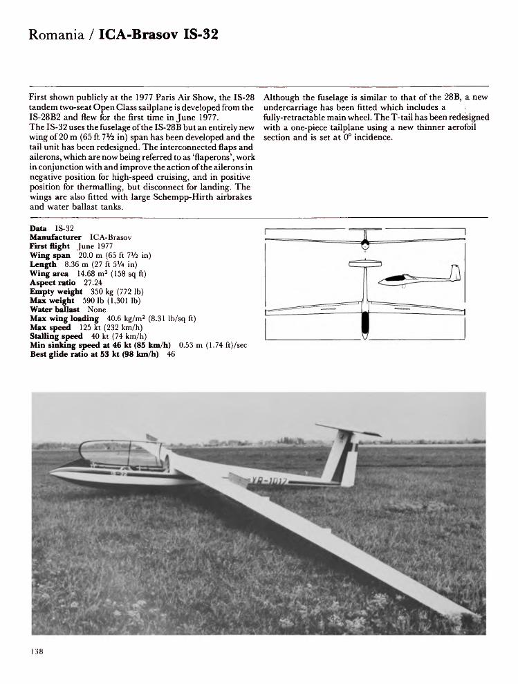
Romania / ICA-Brasov IS-32
First shown publicly at the 1977 Paris Air Show, the IS-28 tandem two-seat Open Class sailplane is developed from the IS-28B2 and flew for the first time in June 1977. The IS-32 uses the fuselage of the IS-28B but an entirely new wing of 20 m (65 ft 7Va in) span has been developed and the tail unit has been redesigned. The interconnected flaps and ailerons, which are now being referred to as 'flaperons', work in conjunction with and improve the action of the ailerons in negative position for high-speed cruising, and in positive position for thermalling, but disconnect for landing. The wings are also fitted with large Schempp-Hirth airbrakes and water ballast tanks.
Although the fuselage is similar to that of the 28B, a new undercarriage has been fitted which includes a fully-retractable main wheel. The T-tail has been redesigned with a one-piece tailplane using a new thinner aerofoil section and is set at 0° incidence.
Data IS-32Manufacturer ICA-BrasovFirst flight June 1977Wing span 20.0 m (65 ft 7¥2 in)Length 8.36 m (27 ft 5% in)Wing area 14.68 m2 (158 sq ft)Aspect ratio 27.24Empty weight 350 kg (772 Ib)Max weight 590 Ib (1,301 Ib)Water ballast NoneMax wing loading 40.6 kg/m2 (8.31 Ib/sq ft)Max speed 125 kt (232 km/h)Stalling speed 40 kt (74 km/h)Min sinking speed at 46 kt (85 km/h) 0.53 m (1.74 ft)/secBest glide ratio at 53 kt (98 km/h) 46
138
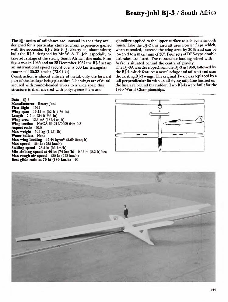
Beatty-Johl BJ-3 / South Africa
The BJ- series of sailplanes are unusual in that they are designed for a particular climate. From experience gained with the successful BJ-2 Mr P. J. Beatty of Johannesburg built the BJ-3, designed by Mr W. A. T. Johl especially to take advantage of the strong South African thermals. First flight was in 1965 and on 28 December 1967 the BJ-3 set up an international speed record over a 500 km triangular course of 135.32 km/hr (73.01 kt).Construction is almost entirely of metal, only the forward part of the fuselage being glassfibre. The wings are of dural secured with round-headed rivets to a wide spar; this structure is then covered with polystyrene foam and
glassfibre applied to the upper surface to achieve a smooth finish. Like the BJ-2 this aircraft uses Fowler flaps which, when extended, increase the wing area by 30% and can be lowered to a maximum of 30°. Four sets of DFS-type double airbrakes are fitted. The retractable landing wheel with brake is situated behind the centre of gravity. The BJ-3 A was developed from the BJ-3 in 1968, followed by the BJ-4, which features a new fuselage and tail unit and uses the existing BJ-3 wings. The original T-tail was replaced by a tall perpendicular fin with an all-flying tailplane located on the fuselage behind the rudder. Two BJ-4s were built for the 1970 World Championships.
Data BJ-3Manufacturer Beatty-JohlFirst flight 1965Wing span 16.15 m (52 ft 11% in)Length 7.5 m (24 ft 7Vi in)Wing area 12.3 m2 (132.4 sq ft)Wing section NACA 66i212/0009-64A-0.8Aspect ratio 20.0Max weight 522 kg (1,151 Ib)Water ballast NoneMax wing loading 42.44 kg/m2 (8.69 Ib/sq ft)Max speed 154 kt (285 km/h)Stalling speed 28.5 kt (53 km/h)Min sinking speed at 40 kt (74 km/h) 0.67 m (2.2 ft)/secMax rough air speed 120 kt (222 km/h)Best glide ratio at 70 kt (130 km/h) 40

Switzerland / FFA Diamant
The Diamant is, as is expected from the Swiss, a beautiful piece of precision engineering. It is a true all-glassfibre sailplane in that every part is made of that material (while most 'glassfibre' sailplanes use plywood and balsa in their construction). Only the flying control system and fittings are of other materials.The fuselage and tail unit were developed at the Swiss Federal Institute of Technology in Zurich under the direction of Professor Rauscher. A prototype fuselage was built in 1962 and flew with Ka 6CR wings, receiving the designation Ka-Bi-Vo. FFA gradually took over development and manufacture of
the Diamant, starting with the HBV-Diamant 15, which used H301 Libelle wings and which first flew on 5 September 1964. Thirteen of this type were built. The Diamant 16.5 is generally similar to the HBV-Diamant 15 but has wings of increased span, designed and built by FFA. A total of 41 had been built when production ended. The Diamant 18 is generally similar to the 16.5 but has wings of 18 m (59 ft OVi in). Accommodation is in a semi-reclining position beneath a forward-sliding canopy. Early models featured a side stick, mounted on the right hand side, but this was moved to the more conventional central position on later models.
Data Diamant 18Manufacturer Flug und FahrzeugwerkeFirst flight February 1968Wing span 18.0 m (59 ft OVz in)Height 1.35 m (4ft 5 in)Length 7.72 m (25 ft 4 in)Wing area 14.28 m2 (154 sq ft)Wing section Wortmann FX-62-Z-153 mod.Aspect ratio 22.7Empty weight 280 kg (617 Ib)Max weight 440 kg (970 Ib)Water ballast NoneMax wing loading 30.8 kg/m2 (6.31 Ib/sq ft)Max speed 129 kt (240 km/h)Stalling speed 32.5 kt (60 km/h)Min sinking speed at 39 kt (72 km/h) 0.52 m (1.71 ft)/secMax rough air speed 108 kt (200 km/h)Best glide ratio at 54 kt (100 km/h) 45
140

Hegetschweiler Moswey 3 / Switzerland
Designed by Georg Miiller, the Moswey series of sailplanes was one of the most significant to emerge from Switzerland during the 25 years following 1930. The Moswey 1, a strutted high-wing training glider of 13.25 m (43 ft 6 in) span, was followed in 1935 by the Moswey 2, with its cantilever, mid-set gull wings of 13.8 m (45 ft 3 in) span. Two years later this sailplane took part in the first International Championships in Germany. The Moswey 2A is a version in which the wing span was increased to 15.5 m (49 ft 10 in). Introduced in 1943, the Moswey 3 met the demand for a small acrobatic sailplane. Like the 2A, the Moswey 3 is made of traditional plywood and fabric, though the wing span is
reduced to 14.0 m (45 ft 11 in). In 1948 the Moswey 3 came third in the World Championships and in the same year, flown by Siegbert Maurer, made the first south-north crossing of the Alps. After the war the Moswey 3 held almost all the Swiss national records and set the first world record for the 100 km triangle. Fourteen 3s were built before the type was superseded by the Moswey 4 in 1950. The Moswey 4, though similar in construction, features a more roomy cockpit, a wing span of 14.4 m (47 ft 3 in) and an unusually large Plexiglas canopy giving excellent visibility.
Data Moswey 3Manufacturer HegetschweilerFirst flight October 1943Wing span 14.0 m (45 ft 11 in)Length 6.0 m (19ft Sin)Height 1.4 m (4ft 7 in)Wing area 13.1 m2 (141 sq ft)Wing section Gottingen 535Aspect ratio 15.0Empty weight 160 kg (353 Ib)Max weight 250 kg (551 Ib)Water ballast NoneMax wing loading 19.1 kg/m2 (3.9 Ib/sq ft)Max speed 113 kt (210 km/h)Stalling speed 27 kt (50 km/h)Min sinking speed at 32 kt (60 km/h) 0.65 m (2.:Max rough air speed 67 kt (125 km/h)Best glide ratio at 38 kt (70 km/h) 27.5
ft)/sec
141

Switzerland / Neukom AN-66C Super-Elfe
This excursion into the field of variable-geometry wing design was Albert Neukom's answer to a request to build the best sailplane in the world. He designed and built it entirely on his own, incorporating some quite innovative technical details, the most striking of which was the chain-operated variable wing flaps, operated by a crank in the cockpit. The 23 m (75 ft SViz in) three-piece wings are constructed of riveted light alloy double T-spars with vacuum pressed plywood sandwich outer skins. The centre section is 6.5 m (21 ft 4 in) in length, the two outer panels each 8.25 m (27 ft 03/4 in) in length. Neukom's specially designed combination of flaps can increase the wing area by 20% when fully
extended, at the same time changing the profile so that wheneither fully extended or fully retracted (the only two possiblepositions) a continuous Eppler profile is achieved. Waterballast is carried in the wing centre section.The fuselage, like that of the earlier AN-66B, has a frontsection of glassfibre and a rear section of plywood and balsasandwich. The V-tail of earlier aircraft in the series has givenway on the AN-66C to a conventional tail unit with hingedelevator.In 1974 a second machine was produced with a four-piecewing of 21 m (68 ft 11 in) span, designated AN-66D.
Data AN-66CManufacturer NeukomFirst flight September 1973Wing span 23.0 m (75 ft 5*/2 in)Length 8.1 m (26 ft 6% in)Height 1.85 m (6 ft 0% in)Wing area 16.0 m 2 (172.0 sq ft)Wing section Eppler 562/569Aspect ratio 33.0Empty weight 420 kg (926 Ib)Max weight 650 kg (1,433 Ib)Water ballast 60 kg (132 Ib)Max wing loading 33.1 kg/m2 (6.8 Ib/sq ft)Max speed 146 kt (270 km/h)Stalling speed 32.5 kt (60 km/h)Min sinking speed at 40.5 kt (75 km/h) 0.5 m (1.64 ft)/secBest glide ratio at 48.5 kt (90 km/h) 48
T
142

Neukom Standard Elfe S-3 / Switzerland
Shortly after the Second World War Albert Neukom brought out a diminutive sailplane aptly named the Elfe 1. It had a wing span of only 9 m (29 ft 6% in) and an empty weight of 43 kg (95 Ib). The span was later increased to 11 m (36 ft 1 in). During 1946-47 Dr W. Pfenninger designed the Elfe 2 with camber-changing flaps and a span of 15.4 m (50 ft 6% in); sink rate was 0.5 m (1.64 ft)/sec and best glide ratio was 37. The Elfe PM3 of 1951, with 16 m (52 ft 6 in) span wings, was disappointingly heavy and was succeeded by the laminar-winged Elfe M.The S-1 prototype of the Standard Elfe first flew on 1 May 1964 and featured a V-tail. The Standard Elfe 2 had a
conventional tail unit, with the tailplane at the base of the fin. The production-type S-3, first flown in May 1966, has the tailplane mounted part-way up the fin. The wing, which is built in three parts, is of balsa-plywood sandwich construction and is fitted with trailing edge airbrakes. The fuselage and tail are of glassfibre and plywood sandwich construction. The landing gear comprises a rubber-sprung retractable monowheel with brake. Flown by Markus Ritzi, a Standard Elfe gained second place in the 1965 World Championships. In the Standard Class competition at the 1968 World Championships, an Elfe S-3 flown by Andrew Smith of the USA was placed first.
Data Standard Elfe S-3Manufacturer NeukomFirst flight May 1966Wing span 15.0 m (49 ft 2Vi in)Length 7.30 m (23 ft 1 iVi in)Height 1.50m (4ft 11 in)Wing area 11.9 m2 (128.1 sq ft)Wing section Wortmann FX SeriesAspect ratio 19.0Empty weight 208 kg (459 Ib)Max weight 320 kg (705 Ib)Water ballast NoneMax wing loading 26.89 kg/m2 (5.5 Ib/sq ft)Max speed 129.5 kt (240 km/h)Stalling speed 30 kt (55 km/h)Min sinking speed at 40 kt (74 km/h) 0.64 m (2.1 ft)/secMax rough air speed 108 kt (200 km/h)Best glide ratio at 51 kt (95 km/h) 37.5
143

Switzerland / Neukom S-4A Elfe 15 and Elfe 17
The S-4A Elfe 15 is a developed version of the Standard Class S-3, from which it differs principally by having a new two-piece strengthened wing fitted with Schempp-Hirth airbrakes, and a more roomy all-plastic forward fuselage of improved aerodynamic shape. The prototype flew for the first time in 1970.The Elfe 17 is a 17 metre Open Class version of the S-4A, employing the same fuselage, but having a two-piece wing of increased span. A maximum of 60 kg (132 Ib) of water ballast can be carried in the wing leading edge. The wings of both versions have an aluminium alloy main spar surrounded by a plywood and foam sandwich. The
fuselage and tail unit are of glassfibre and plywood/foam sandwich construction. The landing gear consists of a rubber-sprung retractable monowheel with brake. Both sailplanes are available as either finished aircraft, assembled but unpainted and unfinished, or as a kit of parts.
Data Elfe 17Manufacturer NeukomFirst flight 1970Wing span 17.0 m (55 ft 9% in)Length 7.1 m (23 ft 3V2 in)Height 1.50 m (4 ft 11 in)Wing area 13.2 m2 (142.1 sq ft)Wing section Wortmann FX-61 -163/60-126Aspect ratio 21.8Empty weight 255 kg (562 Ib)Max weight 380 kg (838 Ib)Water ballast 60kg(1321b)Max wing loading 28.8 kg/m2 (5.9 Ib/sq ft)Max speed 113 kt (210 km/h)Stalling speed 35 kt (65 km/h)Min sinking speed at 40.5 kt (75 km/h) 0.56 m (1.84 ft)/secMax rough air speed 113 kt (210 km/h)Best glide ratio at 48.5 kt (90 km/h) 39
I
144

Pilatus B4-PC11 / Switzerland
The Pilatus B4 is a popular all-metal single-seat Standard Class sailplane. It is suitable both for pilots who have just soloed because of its simple handling characteristics and for the more experienced who appreciate its good performance. The prototype, the B-4 was designed by Ingo Herbot as a private venture and first flew in 1966. Pilatus took over and developed this design and the first flight of the B4-PC11 was made in 1972.The cantilever shoulder wings are in two parts and are built up on a light alloy U-shaped main spar to which the large skin panels are attached by a single row of countersunk rivets. The fuselage is a semi-monocoque structure of light
alloy with flush riveting. The roomy cockpit contains a single semi-reclining seat and is covered by a one-piece canopy. The landing gear consists of a non-retractable main wheel (optionally retractable) and fixed tail wheel in tandem. The main wheel is faired by doors when retracted. The cantilever T-tail is constructed from light alloy with PVC ribs. Elevator trimming is by means of a bias spring. In 1978 the manufacturing and sales rights for the B-4 were acquired by Nippi of Japan, which builds the NP-100 Albatross.
Data B4-PC11 Manufacturer Pilatus First flight 1972 Wing span 15.0 m (49 ft 2Vi in) Length 6.57 m (21 ft 6% in) Height 1.57 m (5 ft 1% in) Wing area 14.04 m2 (151.1 sq ft) Wing section NAG A 643 618 Aspect ratio 16.0 Empty weight 230 kg (507 Ib) Max weight 350 kg (772 Ib) Water ballast NoneMax wing loading 24.93 kg/m2 (5.1 Ib/sq ft) Max speed 129.5 kt (240 km/h) Stalling speed 33.5 kt (62 km/h)Min sinking speed at 39 kt (72 km/h) 0.64 m (2.1 ft)/sec- Max rough air speed 129.5 kt (240 km/h) Best glide ratio at 46 kt (85 km/h) 35
145

United Kingdom / EoN Olympia
The EoN Olympia is an improved version of the German DFS Meise. It was built by Elliotts of Newbury where the late chairman, Mr H.G.C. Buckingham, wishing to use the experience gained during the war when the company manufactured transport gliders and sub-assemblies for many different types of aircraft, entered into co-production with Chiltern Aircraft to build a modernised version of the Meise. Production started at Newbury in 1946 and the prototype first flew in January 1947.Many of the design features which made the Meise famous for its good flying qualities are retained in the Olympia. Its high-set cantilever wood and fabric wings incorporate
D-spars in the leading edge and fabric-covered wooden ailerons. DFS-type airbrakes are fitted. A luggage compartment is built into the fuselage with access on the port side under the wing root. The Olympia 2 has a fixed landing wheel and the Olympia 3 is similar to the Olympia 1 but is fitted with a jettisonable dolly wheel.
Data Olympia 2BManufacturer Elliotts of NewburyFirst flight March 1947Wing span 15.0 m (49 ft 2Vi in)Length 6.61 m (21 ft 8 in)Wing area 15.0 m2 (161.5 sq ft)Wing section Gottingen 549/676Aspect ratio 15.0Empty weight 195 kg (430 Ib)Max weight 304 kg (670 Ib)Water ballast NoneMax wing loading 20.27 kg/m2(4.151b/sqft)Max speed 112 kt (208 km/h)Stalling speed 27 kt (50 km/h)Min sinking speed at 34 kt (63 km/h)0.67 m (2.2 ft)/secMax rough air speed 69 kt(128 km/h)Best glide ratio at 39 kt (72.5 km/h)25
146

EoN 463 / United Kingdom
The EoN 463 is a single-seat Standard Class sailplane, developed from the 460, of which only five were built. The wings of the 460 and 463 are of wooden construction with light alloy spars, aerodynamically similar to those of the 419 but reduced in span to 15m, with the aileron span reduced by 1.5 m at the wingtip. The fabric/stringer top fairing on the 460 fuselage has been replaced with one of glassfibre. The nose section is also of glassfibre construction instead of plywood and a new canopy has been fitted. The fuselage, like that of the 460, is of the fabric-covered Warren girder type. The landing gear consists of a fixed landing wheel but no nose skid. The tailplane is fitted with conventional elevators,
and the whole assembly can be folded up for trailing. The EoN 463 was first flown in 1963 and proved to be very popular with both clubs and private owners. In 1965 two 465s were built in an attempt to improve the performance in competition flying. Several modifications were incorporated, including a reduced fuselage cross-section area. Forty-eight 463s were built before Elliots' management, reviewing the company's activities, elected to close the glider section.
Data 463Manufacturer Elliots of NewburyFirst flight April 1963Wing span 15.0 m (49 ft 2¥2 in)Length 6.4 m (21 ft 0 in)Wing area 12.26 m2 (132 sq ft)Wing section NAG A 643618/421Aspect ratio 18.0Empty weight 181 kg (400 Ib)Max weight 286 kg (630 Ib)Water ballast NoneMax wing loading 23.33 kg/m2 (4.78 Ib/sq ft)Max speed 117.5 kt (218 km/h)Stalling speed 30 kt (56 km/h)Min sinking speed at 37 kt (69 km/h) 0.67 m (2.2 ft)/secMax rough air speed 74 kt (137 km/h)Best glide ratio at 42 kt (78 km/h) 32
147

United Kingdom / Ginn-Lesniak Kestrel
The tandem two-seat semi-aerobatic Kestrel was designed in 1956 by Mr Lesniak and construction was begun by the designer and Mr Vie Ginn at Dunstable Gliding Club's workshops. The aircraft, however, was abandoned and after a gap of some years was rescued from destruction by Messrs Ron Dodd and JefFButt. Mr Dodd, a chartered engineer who had worked at the Royal Aircraft Establishment, Farnborough, recalculated, modified and improved the construction, and with Mr Butt completed the construction, producing a professional-looking two-seat sailplane. The Kestrel is of conventional wood and fabric construction with metal bonded reinforcement at the wing roots. The
two-part wings incorporate large Schempp-Hirth airbrakes and Frise ailerons. The fuselage is all wood with plywood/balsa sandwich reinforcement from the nose cone tojust aft of the cockpit. A large skid block protects the nose. A two-piece canopy covers the roomy cockpit, the transparent detachable aft half of which is secured by the fore section, which is a complete Skylark 4 canopy and is hinged sideways. The Kestrel flew for the first time in July 1969 at Enstone.
Data Ginn-Lesniak KestrelManufacturer R. Dodd & J. ButtFirst flight July 1969Wing span 18.0 m (59 ft OVi in)Length 7.54 m (24 ft 8 3/4 in)Wing area 22.57 m2 (243 sq ft)Wing section Gottingen 549/M12Aspect ratio 14.3Empty weight 308 kg (680 Ib)Max weight 499 kg (1,100 Ib)Water ballast NoneMax wing loading 22.21 kg/m2 (4.55 Ib/sq ft)Max speed 85 kt (158 km/h)Stalling speed 32.5 kt (60 km/h)Min sinking speed at 43 kt (80 km/h) 0.67 m (2.2 ft)/secMax rough air speed 71.5 kt (133 km/h)Best glide ratio 28
148

Kenneth Holmes KH-1/ United Kingdom
The KH-1 is a high-performance sailplane of homebuilt construction, and was entirely designed and built by Mr Kenneth Holmes, a meteorologist. Design began in 1968, construction started in the following year and the KH-1 flew for the first time on 24 November 1971. The cantilever shoulder-set wings are of wood with single aluminium spars joined to plywood webs by epoxy-resin bonding and pop rivets. The closely spaced ribs are covered by a pre-moulded ply/balsa sandwich to 50% chord; aft of this point the covering is 2 mm thick plywood for a further 20% chord and the final 30% is fabric covered. No spoilers are fitted but small-span trailing edge airbrake/flaps are
fitted to the inboard section of the wing. The low profile fuselage is of birch ply covering spruce longerons and plywood frames. The tailplane includes a large fin and rudder of conventional configuration and incorporates an all-moving tailplane with anti-balance tabs controlled by a spring trimmer in the cockpit. The landing gear comprises a retractable monowheel and tail bumper. A tail parachute is fitted for control during approach and for speed limiting purposes.A second version of the KH-1 has been built by John Halford, named the J.S.H. Scorpion (photo below). It first flew in July 1977.
Data KH-1Manufacturer Kenneth HolmesFirst flight November 1971Wing span 18.5 m (60 ft 8l/2 in)Length 7.24 m (23 ft 9 in)Height 1.52 m (5 ft 0 in)Wing area 11.15 m2 (120 sq ft)Wing section Wortmann FX-61 -184/60-126Aspect ratio 31.0Empty weight 222 kg (490 Ib)Max weight 322 kg (710 Ib)Water ballast NoneMax wing loading 28.9 kg/m2 (5.92 Ib/sq ft)Max speed 84.5 kt (157 km/h)Stalling speed 36 kt (67 km/h)Max rough air speed 75 kt (139 km/h)Best glide ratio at 48 kt (89 km/h) 37
149

United Kingdom / Manuel Hawk
Mr W.L. Manuel, previously noted for a number of sailplane designs which culminated in the Willow Wren of 1932, designed and built the Hawk glider as a project during his retirement. It was built at Fairoaks airfield in Surrey during 1968-1970 and was first flown at the College of Aeronautics at Cranfield on 25 November 1972. After some modifications, including increased rudder area, removal of the airbrakes from the lower wing surfaces and an alteration to the aileron controls, the aircraft is again flying. The Hawk is a single-seat sailplane designed for soaring in weak thermal conditions. The conventional three-piece wing consists of a spruce spar with plywood leading edge torsion
box and fabric covering aft of the main spar. The fuselage is a conventional semi-monocoque structure of plywood-covered spruce. The unusual canopy is in three pieces: the front and rear sections are fixed transparent one-piece single curves; the middle section, which is hinged, is a framed double curve. The aircraft is beautifully finished with a high polish on the natural wood and clear dope on the fabric.
Data HawkManufacturer W.L ManuelFirst flight November 1972Wing span 12.8 m (42 ft 0 in)Length 6.25 m (20 ft 6 in)Wing area 13.84 m2 (149 sq ft)Wing section Wortmann FX-61 -184/210Aspect ratio 11.88Empty weight 184 kg (406 Ib)Max weight 290 kg (639 Ib)Water ballast NoneMax wing loading 20.95 kg/m2 (4.29 Ib/sq ft)Max speed 78.5 kt (146 km/h)Stalling speed 31 kt (57.5 km/h)Min sinking speed at 33 kt (61 km/h) 0.77 m (2.53 ft)/secMax rough air speed 64 kt (118.5 km/h)Best glide ratio at 36 kt (66.5 km/h) 25
150

Manuel Condor / United Kingdom
Mr W.L. Manuel, designer of the Willow Wren and more recently the Hawk, disturbed by the loss of lives in hang gliders, has in the Condor provided the answer to those desiring to fly but who have not the financial means to invest in highly priced gliders or the necessary skills to build a modern complex design.The Condor looks unconventional with its metal tube fuselage and steel control cables, but it provides comfortable side-by-side seating arrangement, open to the elements. It is designed especially for hill soaring and has already made several long flights. The tail unit is a large structure of fabric-covered ribs and a tailplane with wide-chord
elevators. Aluminium tubes connect the tail unit to the cockpit section, which is shaped like a boat. The high-set wings are connected to a keel under the cockpit by V-shaped struts on each side. The landing gear consists of a bow-shaped ash skid, using rubber rollers as shock absorbers.The designer does not provide a figure for minimum sink because, in his own words: 'It is designed to go up, and only sometimes will concede to gravity for landing.'
Data CondorManufacturer Manuel, Inwood & InwoodFirst flight August 1976Wing span 15.3 m (50 ft 2Vi in)Length 6.4m (21 ft 0 in)Wing area 23.23 m2 (250 sq ft)Wing section Gottingen 462Aspect ratio 10.0Empty weight 223 kg (492 Ib)Max weight 408 kg (899 Ib)Water ballast NoneMax wing loading 17.57 kg/m2 (3.6 Ib/sq ft)Max. speed 75 kt (139 km/h)Stalling speed 32 kt (59 km/h)Best glide ratio 14
151

United Kingdom / Sigma 1
Operation Sigma was set up in 1966 with the object of building a pre-eminent sailplane for the British entry at the 1970 World Championships at Marfa, Texas. Rear Admiral Nick Goodhart was appointed project manager and manufacture of this very high performance sailplane was financially assisted by companies both within and outside the aviation industry. The idea was that Sigma should have two sets of wings: one for thermalling at low speeds with low minimum sink, and the other for good performance at high speeds for cross-country flying. The two wing sections were specially developed for the project by Dr F.X. Wortmann. The aircraft flew for the first time on 12 September 1971 with Nick Goodhart at the controls. Many aspects of handling and performance had been developed to a satisfactory level, but it did not prove possible to overcome difficulties associated with the flaps and flexible closure plates. Sigma's wing consists of a light alloy box structure with full span flaps. These hydraulically operated flaps move in a similar manner to Fowler flaps but the gap between wing and flap is sealed with a flexible closure plate on the lower surface of the wing and spoilers on the upper surface to form a continuous extension of the wing. Each flap carries a full-span trailing edge aileron on the outer panel, and a camber-changing flap on the inner panel. These surfaces remain exposed when the flap is retracted. With the flap extended the circling speed and low sink rate should give a better rate of climb in weak thermals. Forward of the aileron on the upper surface is a light alloy spoiler to assist with lateral control at low speeds. With the flaps retracted the high
rudder incorporates a brake parachute. The tail unit is of light alloy construction with an all-moving T-tailplane incorporating a full-span anti-balance trim tab. The flying controls are all manually operated except for the flaps and the undercarriage, which are hydraulically operated. The hydraulic pressure is achieved by the pilot pushing both rudder pedals back and forth to operate the hydraulic pump. In 1977 the project was taken over by Prof. David J. Marsden of the University of Alberta, who designed and built the Gemini two-seater sailplane. He proposes to replace Sigma's present flaps by simple slotted flaps in the course of his research on variable geometry sailplanes.
Data Sigma 1Manufacturer Operation Sigma LimitedFirst flight September 1971Wing span 21.0 m (68 ft 10% in)Length 8.81 m (28 ft 10% in)Height 1.83 m (6ft 0 in)Wing area 12.2 m 2 (131.3 sq ft)Wing section Wortmann FX-67 SeriesAspect ratio 36.2Empty weight 607 kg (1,338 Ib)Max weight 703 kg (1,550 Ib)Water ballast NoneMax wing loading 57.6 kg/m2 (11.79 Ib/sq ft)Max speed 140 kt (259 km/h)Stalling speed 37.5 kt (69.5 km/h)Max rough air speed 110 kt (204 km/h)Best glide ratio at 63 kt (117 km/h) 48
wing loading and low drag should give a high lift/drag ratio at high speeds. The braking system is operated by lowering the camber-changing flaps and raising the spoilers on the upper surfaces to control the speed.The fuselage is of the pod and boom type with welded steel tube centre structure faired by the wood framed glassfibre cockpit pod and with the tailboom of light alloy monocoque bolted to it. The long undercarriage is used to ensure that the wing tips have satisfactory ground clearance, necessary due to the large span and the degree of wing flexibility. The retractable sprung tail wheel is mounted in the rudder base and is operated by cables from the main undercarriage. The
152

Slingsby T.13 Petrel / United Kingdom
The best-known name among British sailplane manufacturers is undoubtedly that of the late Frederick N. Slingsby. Having served in the Royal Flying Corps in the First World War he helped to found the Scarborough Gliding Club in 1930 and, from repairing the first Primary the club owned, in his furniture works, soon became a designer and builder of gliders. His first glider, the Falcon I, was a version of the Schleicher Falke, built from plans bought from the German Aero Club. In 19?2 he developed the Falcon 3 side-by-side sailplane. He eventually moved to Kirbymoorside and produced the Kite, Kadet, Tutor and the Gull, which was the first sailplane to cross the English
Channel, from a launch at Dunstable.The Type 13 Petrel first flew in December 1938 and only sixwere built before the start of the Second World War. It wasan 18-metre span gull-winged version of the successfulGerman Rhonadler, constructed from spruce and birchplywood. It had a low wing loading, suitable for the ratherweak thermals encountered in Britain. Initially it was flownwith an all-moving tailplane, but later models had aconventional tailplane-with-elevator.Two are known to be still flying, one in the collection of MikeRussell at Duxford.
Data T.I3 PetrelManufacturer SlingsbyFirst flight December 1938Wing span 17.3 m (56 ft 9 in)Length 7.25 m (23 ft 9V2 in)Wing area 16.72 m2 (180 sq ft)Wing section Gottingen 535Aspect ratio 17.9Empty weight 199 kg (440 Ib)Max weight 289 kg (637 Ib)Water ballast NoneMax wing loading 17.3 kg/m2 (3.54 Ib/sq ft)Max speed 92 kt (170 km/h)Stalling speed 25.5 kt (47 km/h)Min sinking speed at 31 kt (58 km/h) 0.64 m (2.1 ft)/secBest glide ratio at 36 kt (67 km/h) 27
153

United Kingdom / Slingsby T.21B
The T.21, or Sedbergh, has a special place for one generation of British glider pilots. Big, heavy and stable, it was the traditional glider used by clubs and the Air Training Corps for ab initio training for many years. The original T.21 flew for the first time in 1944. There were several initial versions but the T.2 IB became the standard production model. It was first flown in December 1947 and is still used as an ab initio trainer at some gliding clubs. This two-seat side-by-side open cockpit glider is of conventional wooden construction and exceptionally simple design. Large areas of fabric covering allow easy access for major inspections and repairs. The high-set braced wings are
of single-spar construction with torsion-resisting nose box and a light secondary spar to carry the ailerons. The fuselage is of mixed construction: the forward portion back to the two main wing attachment frames is of wood stressed skin construction; the remainder is of fabric-covered wood girder construction.The large wheel, robust skid and sprung tail skid provide an undercarriage which is able to stand up to the vagaries implicit in the early training of pilots. Dual flying controls are provided with the spoiler lever and trimmer positioned on the console between the pilots. The spoilers operate only on the wing upper surfaces.
Data T.2 IB SedberghManufacturer SlingsbyFirst flight December 1947Wing span 16.5 m (54 ft \ l/2 in)Length 8.16 m (26 ft 9% in)Wing area 24.2 m2 (260.5 sq ft)Wing section Gottingen 535Aspect ratio 11.2Empty weight 267 kg (589 Ib)Max weight 475 kg (1,047 Ib)Water ballast NoneMax wing loading 19.6 kg/m2 (4.01 Ib/sq ft)Max speed 92 kt (170 km/h)Stalling speed 28 kt (52 km/h)Min sinking speed at 33.5 kt (62 km/h) 0.85 m (2.79 ft)/secBest glide ratio at 37 kt (69 km/h) 21
154

Slingsby T.31 Tandem Tutor / United Kingdom
The Slingsby T.31 Tandem Tutor is still used in large numbers in Britain by the Air Training Corps under the name Cadet 3, where, with the T.21 Sedbergh, they have constituted the standard training gliders for air cadets for many years. Two hundred T.31s have been built since the prototype first flew in September 1950. The low initial cost coupled with the fact that it can easily be flown either solo or dual made this glider an obvious first choice when new gliding clubs were forming in the 1950s. Based on the single-seat T.8 Kirby Tutor, which first flew in 1937, it uses the same type of wings with wire-braced double struts and the same tail unit. The airframe structure is of
wood and is largely fabric covered. Some T.31s have no spoilers but if requested they could be fitted to the wing upper surfaces. The fuselage is a rectangular wood structure, with a plywood-covered forward section and fabric covering on the rear section. The pilots sit in tandem in separate open cockpits in which the flying controls are fully duplicated. A small windscreen is fitted to each cockpit. Landing gear consists of a main wheel, a large bow nose skid and a tail skid.
Data T.31 Tandem TutorManufacturer SlingsbyFirst flight September 1950Wing span 13.2 m (43 ft 3V2 in)Length 7.1 m (23 ft 3Vi in)Wing area 15.8 m2 (170.1 sq ft)Wing section Gottingen 426Aspect ratio 11.0Empty weight 176 kg (388 Ib)Max weight 376 kg (829 Ib)Water ballast NoneMax wing loading 23.8 kg/m2 (4.87 Ib/sq ft)Max speed 70 kt (130 km/h)Stalling speed 33 kt (61 km/h)Min sinking speed at 36 kt (67 km/h) 1.05 m (3.44 ft)/secBest glide ratio at 39.5 kt (73 km/h) 18.5
155

United Kingdom / Slingsby T.34 Sky
The Sky, a sailplane which must go down in British gliding history for the sheer number of its competition successes alone, won the World Championships in Spain in 1952, flown by the late Philip Wills. Eight T.34 Skys took part and no less than seven were placed in the first fourteen. Skys were placed second in the World Championships of 1954 and 1956.The T.34 was first referred to as the Gull 5 or 'Slingsby 18 metre' but the name Sky, suggested by John Furlong and incorporating the initials of Slingsby, Kirbymoorside and York, was adopted after the prototype had completed its flight trials. It was developed from the Gull 4 and built at the
request of the newly-formed Royal Air Force Gliding andSoaring Association in an attempt to produce a sailplanewith a better performance than that of the well-knownGerman Weihe.Construction of the Sky is of conventional wood and fabric,with a fixed landing wheel. The cockpit is covered by a blownperspex canopy and the rudder pedals are adjustable inflight. The two-piece cantilever wing is fitted with spoilers onthe upper surface.The Sky first flew in 1950 and a total of sixteen were built.
Data T.34 SkyManufacturer SlingsbyFirst flight September 1950Wing span 18.0 m (59 ft OVa in)Length 7.65 m (25 ft \% in)Wing area 17.37 m2 (187 sq ft)Wing section Gottingen 547/NACA 2R 12Aspect ratio 18.7Empty weight 252 kg (556 Ib)Max weight 363 kg (800 Ib)Water ballast NoneMax wing loading 20.9 kg/m2 (4.28 Ib/sq ft)Max speed 98 kt (182 km/h)Stalling speed 29 kt (54 km/h)Min sinking speed at 33.5 kt (62 km/h) 0.66 m (2.17 ft)/secMax rough air speed 72.5 kt (134 km/h)Best glide ratio at 37 kt (69 km/h) 27.5
156

Slingsby T.45 Swallow / United Kingdom
The Slingsby T.45 Swallow is a single-seat glider specifically designed to meet the need for a sailplane to provide solo flying following a two-seater training programme. It is designed not to stall or spin unintentionally even in the hands of an inexperienced pilot, is comparatively robust and has the capacity to absorb a certain amount of rough treatment. Added to this, it has all the features necessary for pilots aiming for their Silver C certificate. The prototype first flew on 11 October 1957 with a 12 m (39 ft 4 in) span wing, but this was changed after initial flight tests to a wing of 13.05 m (42 ft 93/4 in) span. The cantilever wing is of spruce and plywood construction
with a single spar and nose torsion box. Unbalanced wood-framed fabric-covered ailerons are fitted and dive brakes operate above and below each wing. The forward fuselage is a plywood semi-monocoque structure, and the rear section a braced structure of spruce and plywood with fabric-covered sides. The landing gear consists of an unsprung single wheel and rubber-sprung skid. A total of 106 Swallows (not including kits) was built before production was terminated by the fire at Slingsby's Kirbymoorside factory in 1968.
Data T.45 SwallowManufacturer SlingsbyFirst flight October 1957Wing span 13.05 m (42 ft 93/4 in)Length 7.04 m (23 ft iVi in)Height 1.58 m (5 ft 2Vi in)Wing area 13.55 m2 (145.9 sq ft)Wing section NAG A 63s618/4412Aspect ratio 12.6Empty weight 192 kg (423 Ib)Max weight 318 kg (700 Ib)Water ballast NoneMax wing loading 23.47 kg/m2 (4.8 Ib/sq ft)Max speed 122.5 kt (227 km/h)Stalling speed 33.5 kt (62 km/h)Min sinking speed at 36 kt (67 km/h) 0.76 m (2.49 ft)/secMax rough air speed 75 kt (139 km/h)Best glide ratio at 42.5 kt (79 km/h) 26
157

United Kingdom / Slingsby T.43 Skylark 3
In the decade from 1955 to 1966 Britain was in the forefront of glider production, with the Skylark 3 series holding many national and international records. Fred Slingsby said that his first Skylark was built for a lark, hence its name. The single-seat Skylark 1, however, of which two were built (both still flying in 1977), was built with a wing span of 13.72 m (45 ft) but with a three-part wing in order to carry out experiments on the outer panels to discover the best type of lateral control surface. The fuselage was based on that of the Slingsby Prefect and it incorporated very effective airbrakes and a canopy. This little sailplane was ahead of its time but it had a very high stalling speed for an era when the demand was for a sailplane to meet the requirements of an average pilot, so modifications were made and the Skylark 2 (upper photo) was produced.The Skylark 1 was rolled out in March 1953 and the Skylark 2 first flew eight months later. Wing span was increased to 14.63m (48 ft) and a new fuselage of semi-monocoque elliptical section was substituted. Performance was good and the aircraft was found to be a useful addition to club fleets and a stable, highly manoeuvrable acquisition for private owners. A total of sixty-one were built, of which thirty-two had been exported when production ceased in 1962. To meet the demands of the new generation of young glider pilots Slingsby embarked on an enlarged version of the Standard Class Skylark 2 to result in the 18 metre Skylark 3, which has a larger tail unit. Retaining the three-piece wing of earlier Skylarks the 3B had the cockpit moved forward by 76 mm (3 in), repositioning the centre of gravity to compensate for the larger tail. Although the wing centre section is heavy the Skylark is easy to rig, requiring only four pins to attach the main components and a bolt to secure the tailplane. The wing is constructed from spruce and plywood, with a main spar and a light rear spar, ply covering to the rear spar and fabric covering along the trailing edge. In the Types 3C and 3D these spars were strengthened. Type 3F had geared tabs
with airbrakes which operate on both upper and lower wingsurfaces. The cockpit provides adequate room for the largestpilot and variations in pilot size are accommodated by anadjustable seat and rudder pedals. Good visibility isprovided by the one-piece blown canopy, which hingessideways.The landing gear on a few Skylarks consists of a long skidwith a jettisonable dolly wheel, but the majority have a fixedlanding wheel and nose skid.A total of 65 Skylark 3s was produced before the type wassuperseded by the Skylark 4 in 1961.
Data T.43 Skylark 3Manufacturer SlingsbyFirst flight July 1955Wing span 18. 19 m (59 ft 8Vi in)Length 7.62 m (25 ft 0 in)Wing area 16.1 m2 (173.3 sq ft)Wing section NAG A 633620/4415Aspect ratio 20.5Empty weight 248 kg (547 Ib)Max weight 358 kg (789 Ib)Water ballast NoneMax wing loading 22.2 kg/m2 (4.54 Ib/sq ft)Max speed 116.5 kt (216 km/h)Stalling speed 31 kt (58 km/h)Min sinking speed at 35 kt (65 km/h) 0.56 m (1.84 ft)/secBest glide ratio at 40 kt (74 km/h) 36
added to the ailerons and the 3G (lower photo) had a longer,narrower aileron without tabs.The Skylark series uses laminar flow surfaces and is fitted
158

Slmgsby T.43 Skylark 3 / United Kingdom
159

United Kingdom / Slingsby T.50 Skylark 4
Although the Type 50 Skylark is structurally a development of the Skylark 3 its new features and fuselage make it virtually a new design. Most striking are the low clean lines with the wing faired directly into the fuselage. The height of the wing is 23 cm (9 in) lower than that of the Skylark 3 and the 18 m (59 ft Ol/2 in) span wing is almost identical to that of the Skylark 3G except for the modified wing roots. The main spar has been strengthened, cutting out the tendency for the tips to be deflected downwards at speed. First flight of the prototype was in February 1961.The wings are of all-wood construction with plywood covering to the rear spar and a fabric-covered trailing edge.
Airbrakes are fitted to both upper and lower wing surfaces. The fuselage is a semi-monocoque elliptical section wooden structure and is plywood covered. The landing gear consists of a non-retractable monowheel with rim brake and rubber-sprung skids. The tail unit is conventional, with the fin and tailplane plywood covered and the control surfaces fabric covered.A total of sixty-three was built and many are still flying. The Skylark achieved some competition success in 1963 when the type won both the US and Canadian National Championships.
Data T.50 Skylark 4Manufacturer SlingsbyFirst flight February 1961Wing span 18.16 m (59 ft 7 in)Length 7.64 m (25 ft 1 in)Wing area 16.07 m 2 (173 sq ft)Wing section NACA 633620/6415Aspect ratio 20.5Empty weight 253 kg (558 Ib)Max weight 376 kg (829 Ib)Water ballast NoneMax wing loading 23.4 kg/m2(4.79 Ib/sq ft)Max speed 118 kt (219 km/h)Stalling speed 32 kt (60 km/h)Min sinking speed at 37 kt (69 km/h0.53 m (1.74ft)/secMax rough air speed 71 kt(132 km/h)Best glide ratio at 41 kt (76 km/h)36
160

Slingsby T.49B Capstan / United Kingdom
The T.49B two-seat sailplane was developed as a successor to the Slingsby Type 42 Eagle to meet a general requirement for a modern training aircraft. Development work began in 1960 and the prototype first flew in November 1961. Full scale production was initiated in the Spring of 1963. The cantilever high-set wings are of all-wood construction, consisting of a single main spar and plywood leading edge torsion box with fabric covering aft of the spar. The ailerons are plywood covered and dive brakes are fitted to both upper and lower wing surfaces.The forward fuselage structure consists of spruce frames attached to a central keel box with glassfibre covering. The
rear fuselage is a braced wooden girder structure with the bottom skin of plywood and top and sides fabric covered. The landing gear comprises a main skid mounted on a full-length rubber shock absorber and a non-retractable mo no wheel with band brake. A leaf spring tail skid is also fitted. The two seats are arranged side-by-side in an enclosed cockpit covered by a rearward-hinged one-piece canopy. The tail unit is conventional in configuration, with plywood covered fixed surfaces and fabric covered control surfaces. The Capstan is easy to rig, the wings being attached to each side of the fuselage with three pins. A total of thirty-two Capstans was built.
Data T.49 CapstanManufacturer SlingsbyFirst flight November 1961Wing span 16.76 m (55 ft 0 in)Length 8.07 m (26 ft 6 in)Height 1.58 m (5 ft 2Vi in)Wing area 20.43 m2 (220 sq ft)Wing section NAG A 63s620/6412Aspect ratio 13.75Empty weight 345 kg (761 Ib)Max weight 567 kg (1,250 Ib)Water ballast NoneMax wing loading 27.75 kg/m2 (5.68 Ib/sq ft)Max speed 117 kt (217 km/h)Stalling speed 32.5 kt (60 km/h)Min sinking speed at 37.5 kt (70 km/h) 0.66 m (2.17 ft)/secMax rough air speed 80 kt (148 km/h)Best glide ratio at 41 kt (76 km/h) 30
161
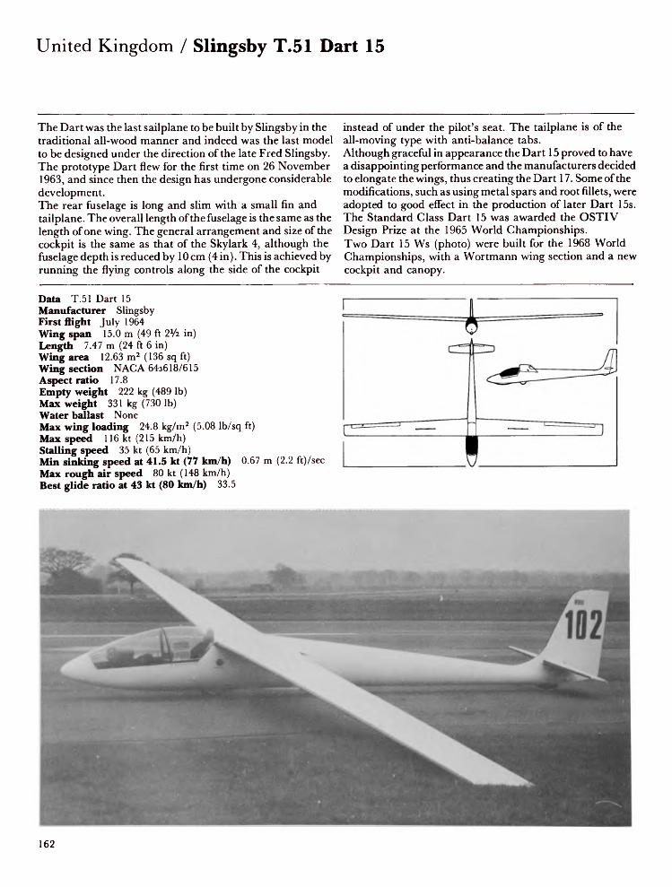
United Kingdom / Slingsby T.51 Dart 15
The Dart was the last sailplane to be built by Slingsby in the traditional all-wood manner and indeed was the last model to be designed under the direction of the late Fred Slingsby. The prototype Dart flew for the first time on 26 November 1963, and since then the design has undergone considerable development.The rear fuselage is long and slim with a small fin and tailplane. The overall length of the fuselage is the same as the length of one wing. The general arrangement and size of the cockpit is the same as that of the Skylark 4, although the fuselage depth is reduced by 10 cm (4 in). This is achieved by running the flying controls along the side of the cockpit
instead of under the pilot's seat. The tailplane is of the all-moving type with anti-balance tabs. Although graceful in appearance the Dart 15 proved to have a disappointing performance and the manufacturers decided to elongate the wings, thus creating the Dart 17. Some of the modifications, such as using metal spars and root fillets, were adopted to good effect in the production of later Dart 15s. The Standard Class Dart 15 was awarded the OSTIV Design Prize at the 1965 World Championships. Two Dart 15 Ws (photo) were built for the 1968 World Championships, with a Wortmann wing section and a new cockpit and canopy.
Data T.51 Dart 15Manufacturer SlingsbyFirst flight July 1964Wing span 15.0 m (49 ft 2Va in)Length 7.47 m (24 ft 6 in)Wing area 12.63 m2 (136 sq ft)Wing section NAG A 64s618/615Aspect ratio 17.8Empty weight 222 kg (489 Ib)Max weight 331 kg (730 Ib)Water ballast NoneMax wing loading 24.8 kg/m2 (5.08 Ib/sq ft)Max speed 116 kt (215 km/h)Stalling speed 35 kt (65 km/h)Min sinking speed at 41.5 kt (77 km/h) 0.67 m (2.2 ft)/secMax rough air speed 80 kt (148 km/h)Best glide ratio at 43 kt (80 km/h) 33.5
162

Slingsby T.51 Dart 17 / United Kingdom
When it became apparent that the 15-metre Dart with wooden spar was too heavy for average soaring conditions in Britain, Slingsby added an extra metre to each wing, using detachable wingtips, and thus produced a 17 metre version. However, investigation showed that the spar required modifications to meet the increased stresses and as a result a change to a metal spar was made.The first Dart 17 with metal spar was rolled out in April 1965. The new wing main spar consists of a single plywood box spar to which light alloy strips have been bonded, two on each side, one at the top and one at the bottom in place of the twin box-section spars. A new trailing edge fillet was added
at the wing root to reduce drag and aileron span was increased by 30 cm (11 3/4 in). The new model was some 16 kg (35V4 Ib) lighter than the 15 metre wooden spar version. An optional retractable landing wheel was made available at the end of 1965. This allows a change of wing incidence and thus avoids the tail high attitude of the sailplane when flying at high speeds. This modified version had the suffix R added to its designation. All-metal tailplanes were also fitted on later machines.Production ended in 1968 after a total of forty-four Dart 17s had been built.
Data T.51 Dart 17RManufacturer SlingsbyFirst flight April 1965Wing span 17.0 m (55 ft 9*/4 in)Length 7.54 m (24 ft 8% in)Wing area 13.74 m2 (148 sq ft)Wing section NAG A 6433618/615Aspect ratio 21.0Empty weight 238 kg (525 Ib)Max weight 370 kg (816 Ib)Water ballast NoneMax wing loading 27.0 kg/m2 (5.53 Ib/sq ft)Max speed 119 kt (220 km/h)Stalling speed 35 kt (65 km/h)Min sinking speed at 40 kt (74 km/h) 0.6 m (1.97 ft)/secMax rough air speed 117 kt (216 km/h)Best glide ratio at 44.5 kt (83 km/h) 36
163

United Kingdom / Slingsby HP-14C
The HP-14C is a Slingsby development of the HP-14 high performance single seat sailplane designed by the American R. Schreder. Slingsby had decided to change over from wood to metal when the use of glassfibre or metal was necessary to remain competitive. They took the basic design of Schreder's sailplane and revised it as necessary to meet British requirements.The V-tail was found to be unsatisfactory for severpi reasons and it was therefore replaced by a conventional fin with all-moving tailplane. The 17-metre wing span was increased to 18 m and the whole wing moved back 15 cm (6 in) to give a wider centre of gravity range and more roomy cockpit. The
flap operating system was completely redesigned: the original rack-and-pinion wind down mechanism was felt to be unsatisfactory since the aerodynamic loads at high speeds made it impossible to apply effectively. A pneumatic system was therefore used, with two jacks to lower the flaps to 90° at VNE, otherwise the flaps are operated manually at normal speeds up to 92 km/hr (50 kt) with the aid of a bungee. The compressed air bottle (at 1,200 Ib/sq in) requires recharging after about three operations of the 90° flap position. The first HP- 14C was completed in time for the 1968 World Championships. Three were built before production ceased after the fire at Slingsby in 1968.
Data HP-14CManufacturer SlingsbyFirst flight April 1968Wing span 18.0 m (59 ft OVi in)Length 7.28 m (23 ft lOVi in)Height 1.19 m (3 ft 11 in)Wing area 13.58 m2 (146.2 sq ft)Wing section Wortmann FX-61-163Aspect ratio 23.9Empty weight 290 kg (639 Ib)Max weight 381 kg (840 Ib)Water ballast NoneMax wing loading 28.1 kg/m2(5.75 Ib/sq ft)Max speed 117 kt (217 km/h)Stalling speed 29.5 kt (55 km/h)Min sinking speed at 45.5 kt(84 km/h) 0.5 m (1.64 ft)/secMax rough air speed 104 kt(193 km/h)Best glide ratio at 52 kt (96 km/h)44
164

Slingsby T.53 / United Kingdom
The T.53 was designed to meet the need for an easily maintained all-metal two-seat trainer for initial or advanced training. Designed by J. Sellars, the original prototype, which first flew on 9 March 1967, had an all-moving tailplane, wing flaps and ailerons of large chord. These were replaced by a conventional fixed tailplane with elevator, the chord of the ailerons was reduced and the flaps were deleted. These changes resulted in a major saving in weight and improved the previously rather high stick forces. The production version, the T.53C, had an extended fin added to the top of the tailplane and the rudder area was increased. The T.53 was Slingsby's first introduction to all-metal
sailplane construction; the decision to change over to all-metal construction was taken because the man hours involved in assembling these aircraft are considerably less than those for wooden ones. Metal is an attractive alternative to wood, being less prone to minor damage and easier and less critical to repair than glassfibre.Sixteen T.53s were built before production was terminated by the 1968 fire. The T.53 design was later purchased by Yorkshire Sailplanes and the type re-entered production as the YS.53. Three had been built by 1974.
Data T.53CManufacturer SlingsbyFirst flight March 1967Wing span 17.0 m (55 ft 6 in)Length 7.7 m (25 ft 3Vi in)Height 1.83 m (6 ft 0 in)Wing area 18.02 m 2 (194 sq ft)Wing section Wortmann FX-61-184Aspect ratio 15.9Empty weight 354 kg (780 Ib)Max weight 580 kg (1,279 Ib)Water ballast NoneMax wing loading 32.2 kg/m2 (6.59 Ib/sq ft)Max speed 117 kt (217 km/h)Stalling speed 40.5 kt (75 km/h)Min sinking speed at 43 kt (80 km/h) 0.76 m (2.5 ft)/secMax rough air speed 80 kt (148 km/h)Best glide ratio at 46 kt (85 km/h) 29
165

United Kingdom / Slingsby T.59D Kestrel 19
After the disastrous fire destroyed Slingsby's Yorkshire factory in September 1968 the financial difficulties which followed resulted in Vickers Ltd taking over the company, which until 1979 traded under the name of Vickers-Slingsby. In September 1969, following the trend of modern sailplane builders, they decided to embark on the production of a glassfibre design. Consequently they entered a licence agreement with Glasfliigel of West Germany to build the Kestrel single-seat Open Class sailplane both in its standard 17-metre form and in a 19-metre developed version as the Slingsby T.59D which first flew in July 1971. Production of Slingsby-built Kestrels began in 1970 and
eleven had been delivered (five 17-metre and six 19-metre) by the end of 1971. Slingsby also built a special 19-metre Kestrel, which is designated T.59C and has a carbon-fibre main spar. This aircraft first flew on 7 May 1971. The wings of the Kestrel 17 were increased to 19 m span on the T.59D by adding half a metre at the wing tips and half a metre at the wing roots. A large fillet was added at the wing roots to reduce drag at low speeds. Other improvements included the introduction of an anti-balance tab on the elevator, giving greater stability, a larger fabric-covered rudder, and the conversion of flaps to flaperons.
Data T.59D Kestrel 19Manufacturer SlingsbyFirst flight July 1971Wing span 19.0 m (62 ft 4 in)Length 6.6 m (21 ft 7 3/4 in)Height 1.47 m (4ft 9% in)Wing area 12.87 m2 (138.5 sq ft)Wing section Wortmann FX-67-K-1707150Aspect ratio 28Empty weight 330 kg (728 Ib)Max weight 472 kg (1,041 Ib)Water ballast 63.6 kg (140 Ib)Max wing loading 36.65 kg/m2 (7.51 Ib/sq ft)Max speed 135 kt (250 km/h)Stalling speed 33 kt (61 km/h)Min sinking speed at 40 kt (74 km/h) 0.52 m (1.71 ft)/secMax rough air speed 105 kt (195 km/h)Best glide ratio at 52.5 kt (97 km/h) 44
166

Slingsby T.59H Kestrel 22 / United Kingdom
The T.59H Kestrel 22 is a special version of the single-seat high performance Kestrel 19 and the prototype, which was produced in 1974, was built by using a Kestrel 19 with two 1.5 metre stub wings, complete with flaps, inserted at the wing roots and an extra fin extension mounted above the tailplane. The idea was to make these modifications available to any owner of the Kestrel 19 who wanted to increase the performance of his sailplane, but it was abandoned in favour of a new aircraft, the Kestrel 22. The new four-piece glassfibre wings, with the joint at the flap/aileron junction, incorporate carbon-fibre spars and large Schempp-Hirth airbrakes on both upper and lower
surfaces. The fuselage has been lengthened by 750 mm (2 ft 4V2 in) by adding a section to the 19m Kestrel just aft of the wing trailing edge. The tail unit is like that of the Kestrel 19 with the weight of the rudder reduced to prevent flutter by cutting panels out of the glassfibre skin and covering with fabric. Landing gear comprises a large Gerdes monowheel and stout undercarriage. The disc brake is operated by a hydraulic unit coupled to the airbrake system.
Data T.59H Kestrel 22Manufacturer SlingsbyFirst flight 1974Wing span 22.0 m (72 ft 2 in)Length 7.55 m (23 ft 9 in)Height 1.94 m (6 ft 4Vi in)Wing area 15.44 m2 (166.2 sq ft)Wing section Wortmann FX-67-K-170/150Aspect ratio 31.35Empty weight 390 kg (860 Ib)Max weight 659 kg (1,450 Ib)Water ballast 100 kg (220 Ib)Max wing loading 42.68 kg/m2 (8.74 Ib/sq ft)Max speed 110 kt (204 km/h)Min sinking speed at 46 kt (85 km/h) 0.48 m (1.57 ft)/secMax rough air speed 105 kt (194.6 km/h)Best glide ratio at 56 kt (104 km/h) 51.5

Slingsby T.61E Falke / United Kingdom
For many years now most gliding clubs have had at least one two-seat motor glider for training purposes. Use of such an aircraft gives clubs the opportunity of speeding up training, dispensing with winch and retrieve vehicles and of cutting down on ground handling. It also makes possible the continuation of training and indeed of flying at all in weather conditions which would otherwise preclude the launching of motorless sailplanes.Air Training Corps cadets have so far used the two-seat T.21 Sedbergh and T.31 Tandem Tutor for the limited training they receive; recently, however, there has been a move to equip them with a motor glider and Slingsby have developed
the T.61E specifically for this purpose. The T.61 is a German design originally built by Scheibe as the successful SF-25B and currently built as the SF-25C Falke. It has been built under licence by Slingsby since 1970, and a total of 35 have been completed. The T.61E is an improved version featuring a glassfibre main spar encased in plywood which simultaneously reduces the empty weight and increases the maximum take-off weight. Many other glassfibre components are used in the aircraft, including a new seat designed to improve comfort and to reduce the hazard of loose articles slipping under the seat into the control area.
Data T.6IE FalkeManufacturer SlingsbyFirst flight April 1977Wing span 15.3 m (50 ft 2V2 in)Length 7.6 m (24 ft 9 in)Wing area 17.5 m 2 (188 sq ft)Wing section ScheibeAspect ratio 13.4Empty weight 375 kg (827 Ib)Max weight 612 kg (1,349 Ib)Water ballast NoneMax wing loading 33.63 kg/m2 (6.88 Ib/sq ft)Max level speed 80 kt (148 km/h)Stalling speed 33 kt (61 km/h)Min sinking speed 1.0 m (3.28 ft)/secBest glide ratio 22Power plant Rollason-Volkswagen 1,600 cc, 35.8kW (48 hp)T-O run 200 m (650 ft)
Rate of climb 122 m (400 ft)/min Range 400 km (216 nm)
168

Slingsby T.65 Vega / United Kingdom
The Vega is the first wholly Slingsby-designed glassfibre sailplane to appear since the collapse of the original Slingsby company in 1969. One of the main design criteria was the ability to take advantage of the rules governing the 15 m Class, which permit the installation of camber-changing flaps. Designed for optimum performance in its class, the Vega has wings with a flap and airbrake speed-limiting system fitted to their trailing edges and operated by a single control in the cockpit. A sideways movement of the control raises or lowers the flaps ± 12° in harmony with the ailerons and changes the camber of the wings. A pull on the lever operates the airbrakes, which are hinged to the flaps with
continuous flexible strips.The cantilever mid-set wings and the tailplane incorporate carbon-fibre spars. The long, slender semi-monocoque fuselage features a comfortable, roomy cockpit, and the one-piece perspex canopy is hinged to open forwards at the nose. Both main and tailwheels are retractable. The first flight was on 3 June 1977. Fifty Vegas has been built by October 1979, and the type has proved itself in several regional and national competitions.
Data VegaManufacturer SlingsbyFirst flight June 1977Wing span 15.0 m (49 ft 2 in)Length 6.72 m (22 ft OV2 in)Wing area 10.05 m 2 (108.2 sq ft)Wing section Wortmann FX-67-K-150/FX-71-L-150Aspect ratio 22.4Empty weight 234 kg (516 Ib)Max weight 440 kg (970 Ib)Water ballast 88 kg (195 Ib)Max wing loading 43.8 kg/m2 (8.97 Ib/sq ft)Max speed 135 kt (250 km/h)Stalling speed 36 kt (67 km/h)Min sinking speed at 44 kt (82 km/h) 0.67 m (2.21 ft)/secBest glide ratio at 60 kt (111 km/h) 42
169

United Kingdom / Swales SD3-15T and 15V
The SD3-15 is a general purpose single-seat 15 metre sailplane designed primarily for clubs and small syndicates. Low capital outlay and running costs have accordingly been combined with safe flying characteristics, low handling weight and small size. Construction of the prototype of this aircraft started in September 1974 and it flew for the first time in March 1975. This aircraft, which is a development of the BG135 designed by J. Gibson, K. Emslie and the late L. Moore, was designated SD3-13V. The prototype is designated SD3-15V (first flight July 1975) and the production aircraft SD3-15T (first flight December 1976), the suffix letter in each case denoting the tail configuration.
The cantilever mid-set wings are built mainly of metal, with metal and polystyrene ribs and wingtips of glassfibre reinforced plastic. The trailing edge airbrakes are all-metal. The fuselage is a semi-monocoque structure of four longerons, metal stressed skin and a nose cone of glassfibre-reinforced plastic. The landing gear consists of a non-retractable monowheel with internally expanding brake.
Data SD3-15TManufacturer SwalesFirst flight December 1976Wing span 15.0 m (42 ft 2*/2 in)Length 6.1 m (20ft 0 in)Height 1.30m (4ft 3 in)Wing area 9.57 m2 (103 sq ft)Wing section Wortmann FX-61-168Aspect ratio 24.0Empty weight 222 kg (490 Ib)Max weight 330 kg (728 Ib)Water ballast NoneMax wing loading 34.48 kg/m2 (7.06 Ib/sq ft)Max speed 109 kt (201 km/h)Stalling speed 35 kt (65 km/h)Min sinking speed at 42 kt (78 km/h) 0.73 m (2.4 ft)/secMax rough air speed 86 kt (159 km/h)Best glide ratio at 48 kt (89 km/h) 36
170

Torva 15 Sport / United Kingdom
Torva was designed as a moderately priced single-seat sailplane with good performance for use by clubs and private owners. Two versions were designed by John Sellars: the Torva 15 Sprite and the Torva 15 Sport, the former for use as a club sailplane and the latter for recreational and competition flying.The Torva company made use of the computer-aided Design Centre to draw the fuselage and canopy sections, the aim being to get a good aerodynamic shape and a comfortable cockpit. Glassfibre-reinforced plastic (GRP) was chosen for the construction, with plywood and foam sandwich frames in the fuselage, and plywood ribs in the wings. A specially
modified Wortmann aerofoil was selected to give a good rate of climb in weak British thermals and also to return a stalling speed low enough to permit short-field landings to be made. The wings include airbrakes, and the Torva Sport is fitted with flaps, the first British-designed modern sailplane to be so. The Sprite has provision for water ballast. The landing gear comprises a sprung main wheel with brake, retractable on the Torva Sport, and a nylon tail wheel. The Torva Sport was first flown on 8 May 1971 by Chris Riddell, who has owned the two existing Torvas since the company closed.
Data Torva 15 SportManufacturer TorvaFirst flight May 1971Wing span 15.0 m (49 ft 21/? in)Length 7.11 m (23 ft 4 in)Wing area 11.3 m2 (121.5 sq ft)Wing section Modified WortmannAspect ratio 20.0Empty weight 238 kg (525 Ib)Max weight 408 kg (900 Ib)Water ballast 59 kg (130 Ib)Max wing loading 36.0 kg/m2 (7.37 Ib/sq ft)Max speed 116.5 kt (216 km/h)Stalling speed 35 kt (65 km/h)Min sinking speed at 43.5 kt (81 km/h) 0.62 m (2.03 ft)/secMax rough air speed 80 kt (148 km/h)Best glide ratio at 44 kt (82 km/h) 37

USA / AmEagle American Eaglet
The American Eaglet, a single-seat self-launching sailplane of unusual configuration, has been designed by Larry Haig primarily as a glider but with a small single-cylinder engine and enough fuel for a single launch. Cost and weight-saving have strongly influenced the design, and the result is a comparatively inexpensive, docile, easy-to-rig sailplane supplied in kits. Design began in 1974 and the prototype first flew on 19 November 1975.The fuselage, of the pod and boom type, includes a compact cockpit with side-mounted control stick and aft-hinged, single-curved canopy. The pod consists of a tubular aluminium frame surrounded by a glassfibre shell faired to
the 5 in (12.7 cm)-diameter aluminium tailboom, which is bolted to the frame. The rear of the cockpit accommodates a 12hp(8.95kW) McCulloch 10 IB engine driving a two-blade 2 ft (60.96 cm)-diameter pusher propeller. The nylon propeller blades fold aft automatically when the engine stops. The 11 m strutted high wings are constructed of spruce spars and contoured urethane foam covered with pre-moulded glassfibre skins. The inverted V-tail is of similar construction. Spoilers are used for braking and lateral control. The landing gear consists of a semi-retractable monowheel and tailwheels on each tailplane half.
Data American EagletManufacturer AmEagleFirst flight November 1975Wing span 10.97 m (36 ft 0 in)Length 4.88 m (16 ft 0 in)Height 0.91 m (3 ft 0 in)Wing area 6.69 m 2 (72.0 sq ft)Wing section Wortmann FX-61-184Aspect ratio 18.0Empty weight 72.5 kg (160 Ib)Max weight 163 kg (360 Ib)Water ballast NoneMax wing loading 24.41 kg/m2 (5.0 Ib/sq ft)Max speed 100 kt (185 km/h)Stalling speed 33 kt (61 km/h)Min sinking speed at 35 kt (65 km/h) 0.76 m (2.5 ft)/secBest glide ratio at 45 kt (84 km/h) 27Powerplant McCulloch 10IB, 8.95 kW (12 hp)
Rate of climb 122 m (400 ft)/min Fuel capacity 2 lit (0.5 US gal)
172

Applebay Zuni / USA
The Zuni, named after an American Indian tribe, is the third design from George Applebay and follows his 21 m (68 ft 11 in) Mescalero, which flew in 1975. The Zuni is a single-seat 15 m Class sailplane of glassfibre/foam sandwich construction. The prototype first flew in New Mexico on 18 November 1976; the production machine appeared in 1977 and has since proved to be a good competition sailplane. The fuselage, with swept T-tail, is similar to that of the Mescalero but shorter, and features a roomy cockpit with a semi-reclining seat and in-flight adjustable rudder pedals under a large one-piece canopy. The controls for flaps and landing gear are mounted on the left-hand side of the cockpit,
with a side-mounted control stick on the right. The all-moving tailplane is trimmed with a press-button on the control stick.The two-piece high-set wings contain control linkages which engage automatically when the sailplane is rigged. The interconnecting flaps and ailerons extend the full span of the wings. Flaps can be lowered to +90° for landing or for use as airbrakes. The landing gear consists of a large manually operated retractable monowheel, designed to withstand landings at maximum weight including water ballast, and a tail wheel.
Data ZuniManufacturer ApplebayFirst flight 18 November 1976Wing span 15.0 m (49 ft 2 l/2 in)Length 6.71 m (22 ft 0 in)Height 1.3 m (4ft 3 in)Wing area 10.13 m2 (109.0 sq ft)Wing section Wortmann FX-67K-1707150Aspect ratio 22.2Empty weight 249 kg (550 Ib)Max weight 544 kg (1,200 Ib)Water ballast 181 kg (400 Ib)Max wing loading 53.7 kg/m2 (11.0 Ib/sq ft)Max speed 180 kt (334 km/h)Stalling speed 34 kt (63 km/h)Min sinking speed at 43.5 kt (80 km/h) 0.52 m (1.71 ft) /sec
173

USA / Bede BD-5S
The BD-5S is a sailplane version of the BD-5 Micro light aircraft, from which it differs principally in having wings increased in span by 3.17 m (10 ft 5 in), modified landing gear and a revised cockpit layout. A prototype was flown in 1975 and like other members of the BD-5 family it is intended for sale in plan and kit form for amateur construction. The low-set wings are attached to the fuselage by sliding the tubular spar on to the root section and securing it by two bolts on each side. The wings feature conventional ailerons and four-position flaps which extend for almost the full span of the trailing edges and can be drooped to 60°. The landing gear consists of side-by-side twin main wheels, and nose skid,
all fully retractable into the fuselage. The main gear door, which opens forward, also serves as an airbrake. Accommodation consists of a single seat under a detachable framed canopy. An unusual feature is the side-mounted control stick.
Data BD-5SManufacturer Bede AircraftFirst flight 1975Wing span 8.48 m (27 ft 10 in)Length 4.13 m (13 ft 6% in)Wing area 5.57 m2 (60 sq ft)Wing section NAG A 64i212Aspect ratio 12.88Empty weight 102 kg (225 Ib)Max weight 193 kg (425 Ib)Water ballast NoneMax wing loading 34.65 kg/m2 (7.09 Ib/sq ft)Max diving speed 174 kt (322 km/h)Stalling speed 34 kt (63 km/h)Min sinking speed at 43 kt (80 km/h) 0.95 m (3.12 ft)/secBest glide ratio 23
174

Briegleb BG 12BD / USA
William C. Briegleb built and flew his first glider in 1928, and just before the Second World War he designed the high-wing strutted BG 6 and BG 7. The BG 6 was originally type certificated in 1941 and was used by both civilians and by the US Army Air Corps.The BG 12 series are single-seat high-performance sailplanes, the prototype of which flew for the first time in 1956. Although the pre-war BG models employed a fabric-covered steel fuselage, the BG 12 series is of conventional wooden construction with ply covering. The wing ribs and fuselage bulkheads are cut from plywood and construction is similar to that of a model aeroplane with
spruce longerons covered with Vs inch plywood. The trailing edge flaps and ailerons are Vie inch ply-covered structures. The conventional tail unit is of wooden construction with ground adjustable tailplane incidence. The landing gear consists of a fixed wheel with Briegleb circumferential brake, and nose skid.Of the four versions produced, model A is in kit form with a 15% thickness-chord three-piece wing; model B has an 18% section two-piece wing and was developed in 1963; model C is a Standard Class version with airbrakes and model BD is the current version.
Data BG 12BDManufacturer Sailplane Corporation of AmericaFirst flight July 1973Wing span 15.0 m (49 ft IVi in)Length 6.68 m (21 ft 11 in)Height 1.22 m (4ft 0 in)Wing area 13.1 m2 (141 sq ft)Wing section NAG A 4415/4406RAspect ratio 17.9Empty weight 227 kg (500 Ib)Max weight 340 kg (750 Ib)Water ballast NoneMax wing loading 25.95 kg/m2 (5.31 Ib/sq ft)Max speed 121 kt (225 km/h)Stalling speed 33 kt (61 km/h)Min sinking speed at 41 kt (76 km/h) 0.69 m (2.26 ft)/secMax rough air speed 112 kt (210 km/h)Best glide ratio at 45 kt (84 km/h) 33
175

USA / Briegleb BG 12-16
In the 1960s William Briegleb developed the single-seat BG 12BR, which Ross Briegleb flew to seventh place in the 1964 National Championships. Later, when the fuselage was damaged in a landing accident it was replaced by a fuselage which had been built for a projected new design, the BG 16. The BG 12-16 is easily recognised by its unusual forward-swept tail unit. It features a low profile fuselage slimmer than that of the BG 12 with a fore section of glassfibre, longer flaps and an all-flying tailplane with two anti-balance servo tabs. The tailplane is of metal construction with glassfibre covering, built in two halves. Construction of the wings is similar to that of the BG 12. The
flaps, ailerons and rudder are of ply-covered wood using spruce and Douglas fir. Accommodation consists of a single semi-reclining seat under a two-piece canopy, the aft section of which is detachable. The landing gear consists of a large non-retractable unsprung monowheel, a shock-absorbing nose skid and sprung tail wheel or tail skid. The first flight took place in June 1969 and since then many kits have been sold in the USA.
Data BG 12-16Manufacturer Sailplane Corporation of AmericaFirst flight June 1969Wing span 15.24 (50 ft 0 in)Length 7.32 m (24 ft 0 in)Height 1.27 m (4 ft 2 in)Wing area 13.2 m 2 (142.1 sq ft)Wing section NAG A 4415R/4406RAspect ratio 17.9Empty weight 238 kg (525 Ib)Max weight 385 kg (850 Ib)Water ballast NoneMax wing loading 29.17 kg/m2 (5.97 Ib/sq ft)Max speed 121 kt (225 km/h)Stalling speed 29.5 kt (55 km/h)Min sinking speed at 41.5 kt (77 km/h) 0.68 m (2.23 ft)/secMax rough air speed 112 kt (210 km/h)Best glide ratio at 48.5 kt (90 km/h) 34
176

Bryan HP-15 / USA
When it was announced that the 1970 World Championships would take place at Marfa, Richard Schreder was one of many designers who started to plan a new sailplane to take advantage of the Texan climate. Some of the other sailplanes then being designed were the BJ-3, Glasfliigel 604, Nimbus 1 and Sigma. Unlike these, the HP-15 was designed to meet the Standard Class rules, which had come into force in 1969, allowing retractable landing gear and fixed hinge flaps on 15-metre sailplanes. The HP-15 is an all-metal aircraft using an extremely high aspect ratio of 33 and high wing loading to achieve high-speed performance. The two-spar wings contain three
ribs in each, the intervening space being filled with plastic foam covered by rolled-to-contour metal skins, with plastic leading edges. Metal flaps and drooping ailerons are used for thermalling and landing. The fuselage is all-metal and incorporated the V-tail characteristic of the HP range. The retractable landing gear is fitted with hydraulic shock-absorbing struts, and the tail wheel is steerable. Like many aircraft which are too advanced for their time, it was found to be difficult to control in flight. It did not participate in the World Championships; neither did it enter production.
Data HP-15Manufacturer Bryan Aircraft CorporationFirst flight Summer 1969Wing span 15.0 m (49 ft 2Vi in)Length 7.07 m (23 ft 2Vi in)Wing area 6.97 m2 (75 sq ft)Wing section Schreder 69-180Aspect ratio 33Empty weight 150 kg (331 Ib)Max weight 272 kg (600 Ib)Water ballast NoneMax wing loading 39.0 kg/m2 (7.99 Ib/sq ft)Max speed 130 kt (241 km/h)Stalling speed 30 kt (56 km/h)Min sinking speed at 39 kt (72 km/h) 0.49 m (1.6 ft)/secMax rough air speed 98.5 kt (183 km/h)Best glide ratio at 47.5 kt (88 km/h) 45
177

USA / Bryan HP-ISA
The successful designer and pilot Richard E. Schreder, who designed, built and flew the HP-8 to win the US National Championships in 1958 and 1960, and produced the innovatory HP-10, the HP-11, which was placed third in the 1962 World Championships, and the well-known HP-14 (built in the UK as the HP- 14C), is currently producing the Standard Class HP-18 and the HP-ISA. As with many American sailplanes it is sold in kit form for home or club assembly. It is an all-metal aircraft with machined aluminium spars and precut hard foam ribs spaced at 10 cm intervals. A similar rib construction technique is used in the HP- 18A, but the spars are of carbon
fibre. The fuselage is supplied as a pre-formed Kevlar pod, aluminium body and V-tail. A two-piece flush canopy covers the cockpit.The cantilever shoulder-set wings feature camber-changing flaps and ailerons running the length of the trailing edge. A retractable landing wheel with brake and a steerable tailwheel comprise the landing gear.
Data HP-18AManufacturer Bryan Aircraft CorporationFirst flight 1975Wing span 15.0 m (49 ft 2 a/2 in)Length 7.16 m (23 ft 0 in)Height 1.22 m (4 ft 0 in)Wing area 10.66 m2 (114.7 sq ft)Wing section Wortmann FX-67-150Aspect ratio 21.1Empty weight 191 kg (420 Ib)Max weight 417 kg (920 Ib)Water ballast 90 kg (200 Ib)Max wing loading 39.12 kg/m2 (8.01 Ib/sq ft)Max speed 130 kt (241 km/h)Stalling speed 28.5 kt (58 km/h)Min sinking speed at 39 kt (73 km/h) 0.52 m (1.7 ft)/secMax rough air speed 104 kt (193 km/h)Best glide ratio 40
178

Bryan RS-15 / USA
This 15 metre sailplane was designed by Richard Schreder to meet current OSTIV Standard Class specifications. It is designed for simple, rapid assembly by the homebuilder and is licensed in the amateur-built Experimental category. No jigs are required, and most major components are prefabricated to reduce assembly time to approximately 500 man-hours for a builder with average mechanical aptitude. The cantilever shoulder-set wings are of all-metal construction except for polyurethane foam ribs spaced at 102 mm (4 in) intervals. The wing spar caps are machined from solid aluminium plate. Water ballast is carried inside the wing box spars. The trailing edge flaps/airbrakes are of
aluminium sheet bonded to foam ribs. The plain ailerons may be coupled to the flaps. The monocoque fuselage comprises a glassfibre forward pod, complete with bulkheads and moulded seat and a 152 mm (6 in) diameter aluminium tube tailboom with V-tail. Accommodation consists of a single seat under a one-piece Plexiglas canopy. Landing gear is a manually-retractable monowheel and non-retractable tailwheel. Hydraulic shock absorbers are fitted to both the main wheel and tailwheel and a hydraulic brake is fitted to the main wheel.
Data RS-15Manufacturer Bryan Aircraft CorporationFirst flight 1973Wing span 15.0 m (49 ft 2l/2 in)Length 6.71 m (22 ft 0 in)Height Height 1.17 m (3 ft 10 in)Wing area 10.5 m2 (113 sq ft)Wing section Wortmann FX-67-K-150Aspect ratio 21.4Empty weight 200 kg (441 Ib)Max weight 426 kg (940 Ib)Water ballast 91 kg (200 Ib)Max wing loading 40.57 kg/m2 (8.31 Ib/sq ft)Max speed 130 kt (241 km/h)Stalling speed 32.5 kt (60 km/h)Min sinking speed at 43 kt (80 km/h) 0.64 m (2.1Max rough air speed 104 kt (193 km/h)Best glide ratio 38
ft)/sec
179

USA / Concept 70
Although it has long been apparent that sailplane manufacturers in the USA prefer to build their aircraft from metal, it would be surprising indeed if they had never used glassfibre. In 1970, in fact, Arthur Zimmerman and Wolfgang Schaer produced the first American all-glassfibre sailplane, the Concept 70. This is a single-seat Standard Class sailplane, production of which began in 1973. By the spring of 1974 some sixteen had been built. The cantilever shoulder-set wings consist of a glassfibre/PVC foam sandwich structure with constant-chord centre section and tapered outer panels. Aluminium flaps on each trailing edge lower to 90°. The
glassfibre monocoque fuselage is reinforced with a steel tube frame connecting the landing gear and wing fittings and continuing into the cockpit area to add strength and rigidity. The cockpit itself is roomy and is fitted with a single semi-reclining seat, recessed for an American-type parachute. The one-piece flush Plexiglas canopy is hinged and jettisonable. The manually-retractable Tost monowheel is fitted with a simple drum brake.
Data Concept 70Manufacturer Berkshire Manufacturing CorporationFirst flight 1970Wing span 15.0 m (49 ft 2V5z in)Length 7.31 m (24ft 0 in)Height 1.83 m (6ft 0 in)Wing area 11.52 m2 (124 sq ft)Wing section Eppler/WortmannAspect ratio 20.0Empty weight 226 kg (500 Ib)Max weight 396 kg (875 Ib)Water ballast 91 kg (200 Ib)Max wing loading 34.38 kg/m2 ((7.04 Ib/sq ft)Max speed 105 kt (195 km/h)Stalling speed 31 kt (58 km/h)Min sinking speed at 43.5 kt (81 km/h) 0.62 m (2.03 ft)/secMax rough air speed 105 kt (195 km/h)Best glide ratio at 52 kt (96.5 km/h) 40
180

DSK BJ-1 Duster / USA
The BJ-1 Duster may be said to epitomise gliding as a hobby rather than as a competitive sport. It was designed specifically for amateur construction and no component exceeds 5.5 m (18 ft) so that it can be built in the home and stored in the garage. It was designed by Ben Jansson, an aerodynamicist who captained the Swedish teams in the World Championships at Leszno and Marfa, and by H. Einar Thor, an American aeronautical engineer. The prototype BJ-1 first flew in August 1966 after two-and-a-half years of development.It is a small all-wood aircraft with three-piece wings incorporating a spruce main spar and trailing edge
airbrakes. The fir plywood fuselage shell has a hexagonal cross section at the front and a triangular cross section aft of the wing. Landing gear consists of a main wheel, tail wheel and nose skid.The BJ-1B is a modified version in which the weight is reduced, the wing span slightly increased and the Plexiglas canopy reduced in height to allow the pilot to sit in a semi-reclining position. Since its introduction, DSK Aviation has supplied more than 200 Duster kits in the USA and throughout the world.
Data BJ-1 DusterManufacturer DSK Aviation CorporationFirst flight August 1966Wing span 13.0 m (42 ft 7% in)Length 6.1 m (20 ft 0 in)Wing area 9.60 m2 (103.3 sq ft)Wing section NAG A 4415Aspect ratio 17.7Empty weight 159 kg (350 Ib)Max weight 263 kg (580 Ib)Water ballast NoneMax wing loading 27.4 kg/m2 (5.61 Ib/sq ft)Max speed 111 kt (206 km/h)Stalling speed 34.5 kt (64 km/h)Min sinking speed at 67 kt (124 km/h) 1.8 m (5.9 ft)/secMax rough air speed 80 kt (148 km/h)Best glide ratio at 47 kt (87 km/h) 29
181

USA / Laister LP-15 Nugget
Design and construction of the LP-15 Nugget prototype began in February 1971 by Jack Laister and son Bill, an aerodynamicist. First flight was in June 1971 with certification in mid-1975. Although design work had started in 1970 the manufacturers waited for the CIVV conference on Standard Class requirements before starting construction, leaving only two-and-a-half months for its completion; its maiden flight was also a contest flight. The cantilever shoulder-set wings are of Chem-Weld bonded aluminium alloy structure and feature long span trailing edge flaps with negative travel (up) for high-speed flight, 8° positive travel (down) for thermalling and 85° positive for
landing or use as airbrakes. The top-hinged plain ailerons are of similar construction. The fuselage is a semi-monocoque structure with a forward portion of moulded glassfibre and a rear portion of bonded aluminium alloy which incorporates a cantilever T-tail with slightly swept fin and rudder.Accommodation consists of a single semi-reclining seat under a fully-transparent two-piece canopy with a removable section and sliding ventilation panel.
Data LP-15 NuggetManufacturer LaisterFirst flight June 1971Wing span 15.0 m (49 ft 2 ¥2 in)Length 6.1 m (20 ft 0 in)Height 1.27 m (4 ft 2 in)Wing area 10.13m2 (109 sq ft)Wing section WortmannAspect ratio 22.1Empty weight 210 kg (463 Ib)Max weight 408 kg (900 Ib)Water ballast 84 kg (185 Ib)Max wing loading 40.28 kg/m2 (8.25 Ib/sq ft)Max speed 126 kt (233 km/h)Stalling speed 34 kt (63 km/h)Max rough air speed 126 kt (233 km/h)Best glide ratio at 48 kt (89 km/h) 36
182

Laister LP-49 / USA
Jack Laister designed and built his first gull-winged acrobatic sailplane in 1938. During the Second World War he worked on the military glider programme and with Mr Kauffmann developed the LK, which was produced in quantity for the military under the designation of TG4A. On July 4 1966 a new single seat high-wing sailplane, the LP-46, was rolled out. It was the prototype of the popular LP-49, familiar to Americans as the 'Forty-Niner'. It is a handsome single-seat Standard Class sailplane with metal laminar flow wings and is designed to be sold in kit form. The extruded aluminium main spar booms are curved in a chordwise direction to follow the aerofoil section, while the
roll-contoured sheet aluminium skin is butted and flush riveted with blind pop rivets.The fuselage is a semi-monocoque structure consisting of two pre-moulded glassfibre halves reinforced with aluminium bulkheads and fittings. The tail unit is a cantilever aluminium structure with sweptback fin and rudder. Landing gear consists of retractable main wheel with brake, glassfibre nose skid with steel shoe, and with non-retractable shrouded tailwheel replacing the retractable wheel of earlier models.More than 50 kits had been sold by early 1976, and about 35 of these had been completed and flown.
Data LP-49Manufacturer Laister Sailplanes Inc.First flight July 1966Wing span 15.0 m (49 ft 2l/2 in)Length 6.28 m (20 ft 7V4 in)Wing area 13.28 m2 (143 sq ft)Wing section NAG A 643618Aspect ratio 17.0Empty weight 208 kg (460 Ib)Max weight 408 kg (900 Ib)Water ballast NoneMax wing loading 30.72 kg/m2 (6.29 Ib/sq ft)Max speed 117 kt (217 km/h)Stalling speed 30 kt (56 km/h)Min sinking speed at 43 kt (80 km/h) 0.63 m (2.07 ft)/secMax rough air speed 117 kt (217 km/h)Best glide ratio at 50 kt (92.5 km/h) 36.5
183

USA / Maupin Woodstock One
The Woodstock is a small, simple and inexpensive single-seat wood-and-fabric sailplane for the do-it-yourself builder who has to work to a limited budget. It was designed by Jim Maupin, with advice from Irv Culver, who has designed several sailplanes.The slender, lightweight fuselage, made of ply wood-covered wood, is of hexagonal section forward of the wings and triangular aft. The cockpit accommodates the pilot in semi-reclining position under a single-curved Plexiglas canopy. The shoulder-set cantilever wings are joined by two half-inch (13 mm)-diameter steel pins and secured to the fuselage with three quick-release pins. The wing has a
plywood leading-edge D-spar, fabric-covered aft of the spar. Plain, all-wood ailerons are fitted, with upper-surface wooden spoilers for landing control. The wheel is braked by the application of direct pressure to the tyre by means of an aluminium strap activated by a lever on the control column. The tail unit is conventional, with the fin and tailplane plywood-covered and the control surfaces fabric-covered. The whole sailplane can be built on a simple 18 ft (5.5m) -long trestle and no special jigs or fixtures are needed.
Data Woodstock OneManufacturer Jim MaupinFirst flight Spring 1978Wing span 11.89 m (39 ft 0 in)Length 5.43 m (17 ft 10 in)Height 1.22 m (4ft 0 in)Wing area 9.73 m2 (104.7 sq ft)Wing section Irv CulverAspect ratio 14.5Empty weight 106.5 kg (235 Ib)Max weight 204 kg (450 Ib)Water ballast NoneMax wing loading 20.9 kg/m2 (4.3 Ib/sq ft)Min sinking speed 0.79 m (2.6 ft)/secBest glide ratio 24
184

Miller Tern 2 / USA
The Tern is a single-seat sailplane with a good performance and simplified construction, designed by Terry Miller for home-builders. Many are under construction in the USA and plans for the aircraft have been sold throughout the world. The Tern 2 is an improved version of the Tern 1, with increased wing span and a drogue parachute fitted in the base of the rudder. The prototype Tern first flew in September 1965, and the Tern 2 made its first flight three years later, in August 1968.The cantilever shoulder-set wings are of two-piece two-spar construction and are all-plywood covered. Plain all-wood ailerons are fitted and lower-surface wooden spoilers fitted
for landing control. The fuselage is a semi-monocoque wooden structure with a glassfibre nose and plywood skin aft of the cockpit. Accommodation comprises a single semi-reclining seat under a three-piece canopy, the centre part of which hinges sideways. The non-retractable landing wheel is located forward of the CG, and there is a skid under the nose. Wheel braking is by the application of direct pressure to the tyre. The tail unit is a conventional cantilever all-wood structure with special hingeline contouring to reduce drag and increase control effectiveness at large deflections.
Data Tern 2Manufacturer MillerFirst flight August 1968Wing span 15.56 m (51 ft OV2 in)Length 6.49 m (21 ft 3Va in)Height 1.52 m (5ft 0 in)Wing area 13.01 m2 (140 sq ft)Wing section Wortmann 61 SeriesAspect ratio 22.0Empty weight 249 kg (550 Ib)Max weight 363 kg (800 Ib)Water ballast NoneMax wing loading 27.9 kg/m2(5.71 Ib/sqft)Max speed 104 kt (193 km/h)Stalling speed 34.5 kt (64 km/h)Min sinking speed at 41.5 kt(77 km/h) 0.59 m (1.94 ft)/secMax rough air speed 76.5 kt(142 km/h)Best glide ratio at 52 kt (97 km/h)38
185

USA / Monnett Monerai
The Monerai is one of a new breed of small, light sailplanes available in kit form and benefiting from modern construction methods. Designed and built by John Monnett of Illinois, the prototype flew for the first time in February 1978 with Monnett himself at the controls. The fuselage is of the pod and boom type, the cockpit being a welded chrome-molybdenum steel tube structure enclosed in a streamlined glassfibre pod; a tubular aluminium tailboom is bolted to the pod. The pilot is accommodated in a reclining sling-type seat, and headrest and rudder pedals are adjustable. The control stick is mounted on the right of the cockpit. On the left a lever operates the trailing-edge
flaps, which travel from —8° to +90°. The landing gear consists of a non-retractable monowheel and a tailskid. The constant-chord wing is constructed by bonding aluminium skins to a machined aluminium spar and pressed ribs. Each wing panel weighs only 23.6 kg (52 Ib), making rigging easy. Like the wing, the V-tail has pressed aluminium ribs. The all-moving tailplane has its port panel slightly forward of the starboard panel; the two are identical and interchangeable.There is provision in the basic design for a power unit for self-launching.
Data Monerai SManufacturer MonnettFirst flight February 1978Wing span 11.0 m (36 ft 0 in)Length 6.0 m (19 ft 7 in)Height 89 cm (35 in)Wing area 7.25 m 2 (78 sq ft)Wing section Wortmann FX-61192 modAspect ratio 16.6Empty weight 99.8 kg (220 Ib)Max weight 204.12 kg (450 Ib)Water ballast NoneMax wing loading 28.12 kg/m2 (5.76 Ib/sq ft)Max speed 104 kt (193 km/h)Stalling speed 33 kt (61 km/h)Min sinking speed at 48 kt (89 km/h) 0.85 m (2.8 ft)/secMax rough air speed 78 kt (145 km/h)Best glide ratio at 52 kt (97 km/h) 28
186

Ryson ST-100 Cloudster / USA
Believed to be the first American motor glider designed for production, the ST-100 has the traditional tractor propeller configuration of the most popular European powered sailplanes. Its design, which was started in March 1974, incorporates many basic advances for this class of aircraft, such as all-metal construction, fully folding wings, power-operated flaps and linked ailerons. Construction of the prototype started in July 1974 and the aircraft flew for the first time on 21 December 1976.The cantilever low-set wings are of all-metal construction and feature electrically operated trailing edge flaps which are interconnected with the ailerons and operate together from
-12° to +8°, after which the flaps travel to + 72° for braking. The fuselage is a conventional all-metal semi-monocoque structure and incorporates a cantilever T-tail with sweptback fin and rudder and non-swept horizontal surfaces. The two-wheeled main gear and steerable tail wheel are both non-retractable. Accommodation consists of seats for two persons in tandem under a fully transparent one-piece framed canopy which opens sideways. The Cloudster is powered by a 74.5 kW (100 hp) Continental 0-200 flat-four engine driving a Hoffmann three-position propeller.
Data ST-100 CloudsterManufacturer Ryson Aviation CorporationFirst flight December 1976Wing span 17.58 m (57 ft 8 in)Length 7.78 m (25 ft 6Va in)Height 1.78 m (5 ft 10 in)Wing area 19.79 m2 (213 sq ft)Wing section Wortmann FX-67-170/17Aspect ratio 15.61Empty weight 550 kg (1,212 Ib)Max weight 748 kg (1,650 Ib)Water ballast NoneMax wing loading 37.8 kg/m2 (7.74 Ib/sq ft)Max level speed at S/L 130 kt (241 km/h)Stalling speed 37 kt (69 km/h)Min sinking speed 0.89 m (2.93 ft )/secBest glide ratio 28Power plant Continental O-200, 74.5 kW (100 hp)
T-O run 174m (570ft)Max rate of climb at S/L 273 m (895 ft)/minRange 1,103 km (595 nm)
187

USA / Schweizer 1-23
In the early 1930s the Schweizer brothers - Ernie, Paul and Bill - built their first glider, the single-seat SGU 1-1, and in 1935 they formed the Schweizer Aircraft Corporation. During the war they produced military training gliders and diversified into aircraft components. Designs from this period include the 1-19 of 1944, the well-known 2-22 of 1945, the 1-21 of 1947 and the 1-23 of 1948, the last of which won numerous national championships. At this time also American sailplane designers were moving from fabric-covered steel tube frames to all-metal structures comprising monocoque aluminium fuselages and stressed-skin aluminium wings. The 1-23 was one of the first
of this type of sailplane to enter series production.A total of 69 SGS l-23s of all versions have been produced.The Standard has a wing span of 13.36 m (43.83 ft). In the B,C and D the span was increased to 15.24 m (50.0 ft). The1-23E, introduced in 1954 with a wing span of 16.09 m (52.8ft), has a thicker wing skin, and butt joints replace the lapjoints on the Type F. The models G and H had a larger fin,and the H-15 has detachable wingtips to meet StandardClass requirements.In 1961 a 1-23E flown by Paul Bikle set the current worldaltitude record of 14,102 m (46,267 ft).
Data SGS 1-23DManufacturer SchweizerFirst flight 1952Wing span 15.24 m (50.0 ft)Length 6.25 m (20 ft 4 in)Height 1.52 m (5 ft 0 in)Wing area 14.9 m 2 (160 sq ft)Wing section NAG A 43012A/23009Aspect ratio 15.6Empty weight 190 kg (420 Ib)Max weight 340 kg (750 Ib)Water ballast NoneMax wing loading 22.8 kg/m2 (4.6 Ib/sq ft)Max speed 114 kt (212 km/h)Stalling speed 28 kt (52 km/h)Min sinking speed at 30 kt (55 km/h) 0.61 m (1.86 ft)/secBest glide ratio at 41.5 kt (77 km/h) 30
188
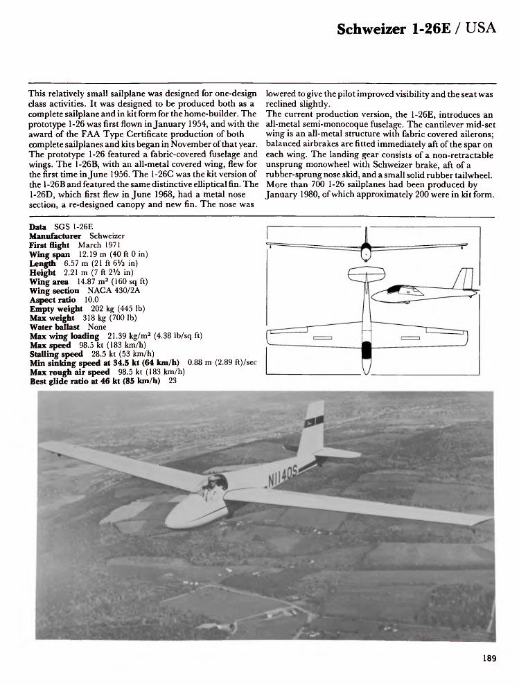
Schweizer 1-26E / USA
This relatively small sailplane was designed for one-design class activities. It was designed to be produced both as a complete sailplane and in kit form for the home-builder. The prototype 1-26 was first flown in January 1954, and with the award of the FAA Type Certificate production of both complete sailplanes and kits began in November of that year. The prototype 1-26 featured a fabric-covered fuselage and wings. The 1-26B, with an all-metal covered wing, flew for the first time in June 1956. The 1-26C was the kit version of the 1-26B and featured the same distinctive elliptical fin. The 1-26D, which first flew in June 1968, had a metal nose section, a re-designed canopy and new fin. The nose was
lowered to give the pilot improved visibility and the seat was reclined slightly.The current production version, the 1-26E, introduces an all-metal semi-monocoque fuselage. The cantilever mid-set wing is an all-metal structure with fabric covered ailerons; balanced airbrakes are fitted immediately aft of the spar on each wing. The landing gear consists of a non-retractable unsprung monowheel with Schweizer brake, aft of a rubber-sprung nose skid, and a small solid rubber tailwheel. More than 700 1-26 sailplanes had been produced by January 1980, of which approximately 200 were in kit form.
Data SGS 1-26EManufacturer SchweizerFirst flight March 1971Wing span 12.19 m (40 ft 0 in)Length 6.57 m (21 ft 6V2 in)Height 2.21 m (7 ft 2V2 in)Wing area 14.87 m2 (160 sq ft)Wing section NACA 430/2AAspect ratio 10.0Empty weight 202 kg (445 Ib)Max weight 318 kg (700 Ib)Water ballast NoneMax wing loading 21.39 kg/m2 (4.38 Ib/sq ft)Max speed 98.5 kt (183 km/h)Stalling speed 28.5 kt (53 km/h)Min sinking speed at 34.5 kt (64 km/h) 0.88 m (2.89 ft)/secMax rough air speed 98.5 kt (183 km/h)Best glide ratio at 46 kt (85 km/h) 23

USA / Schweizer 2-32
The SGS 2-32 high-performance sailplane has an unusually large cabin capable of carrying one very large or two average-sized passengers in addition to the pilot. The prototype flew for the first time on 3 July 1962. FAA Type Approval was received in June 1964 and production began immediately. More than 88 had been built byjanuary 1977. A number of world and national gliding records have been gained by pilots flying this sailplane. The 2-32 was also chosen to form the basic airframe of the Lockheed YO-3A quiet observation aircraft and the E-Systems L450F. The cantilever mid-set wings are of all-metal single-spar construction with metal covering; the metal ailerons are
fabric covered. Speed limiting spoiler-type airbrakes are fitted to both upper and lower wing surfaces. The tail unit is a cantilever metal structure with all-moving tailplane and adjustable trim tab; control surfaces are fabric-covered. The landing gear consists of a large non-retractable unsprung monowheel with hydraulic brake, a tail skid and sprung wing tip wheels.The accommodation is arranged beneath a sideways opening blown canopy. The rear control column can be removed for passenger comfort.
Data SGS 2-32Manufacturer SchweizerFirst flight July 1962Wing span 17.4 m (57 ft 1 in)Length 8.15 m (26 ft 9 in)Wing area 16.7 m 2 (180 sq ft)Wing section NAG A 633618/43012AAspect ratio 18.05Empty weight 385 kg (849 Ib)Max weight 649 kg (1,430 Ib)Water ballast NoneMax wing loading 38.8 kg/m2 (7.94 Ib/sq ft)Max speed 122 kt (225 km/h)Stalling speed 44 kt (81 km/h)Min sinking speed at 44 kt (80 km/h) 0.72 m (2.38 ft)/secBest glide ratio at 51 kt (95 km/h) 34
190

Schweizer 2-33A / USA
The SGS 2-33 was originally developed from the 2-22, with increased wing span and higher performance. The 2-22, with its development B, C, D and E models, was the most popular two-seat training sailplane in America following its introduction in 1948; 258 were built. The prototype 2-33 was first flown in the Autumn of 1966 and received FAA Type Approval in February 1967. Production began in January 1967 and more than 560 2-33s had been built by January 1980; the type is also available in kit form. The strut-braced high-set wings are of aluminium alloy construction with metal skinning and all-metal ailerons; spoilers are fitted to both upper and lower wing surfaces. The
fuselage is a welded chrome-molybdenum steel tube structure with the nose covered with glass-fibre and the remainder being fabric-covered. The landing gear is a non-retractable Cleveland monowheel immediately aft of the nose skid. Wing-tip wheels are also fitted. The two seats are arranged in tandem beneath a one-piece canopy hinged to the left. The rear pilot has fixed clear panels at the sides and above, and a door on the right. The 2-33A has become the standard training sailplane in North America and is also exported to other countries.
Data SGS 2-33AManufacturer SchweizerFirst flight 1966Wing span 15.54 m (51 ft 0 in)Length 7.85 m (25 ft 9 in)Height 2.83 m (9 ft 3V2 in)Wing area 20.39 m2 (219.5 sq ft)Wing section NAG A 633618Aspect ratio 11.85Empty weight 272 kg (600 Ib)Max weight 472 kg (1,040 Ib)Water ballast NoneMax wing loading 23.14 kg/m2 (4.74 Ib/sq ft)Max speed 85 kt (158 km/h)Stalling speed 30.5 kt (57 km/h)Min sinking speed at 33 kt (61 km/h) 0.91 m (2.99 ft)/secBest glide ratio at 45.5 kt (84 km/h) 23

USA / Schweizer SGS 1-34
Design of this single-seat high-performance Standard Class sailplane, intended to replace the 1-23 series, began in 1967 and construction of the prototype started in the following year. This flew for the first time in the Spring of 1969 with FAA Type Certification following in September of that year. More than 100 production models had been completed by January 1980.The cantilever shoulder-set wings are of all-metal aluminium alloy construction with plain all-metal differential ailerons and speed limiting spoiler-type airbrakes fitted both above and below each wing. The fuselage is an all-metal aluminium alloy semi-monocoque
structure incorporating a cantilever all-metal tail assembly. The landing gear consists of a non-retractable monowheel with forward skid and auxiliary tailwheel. A retractable monowheel is available as an optional extra. Accommodation consists of a single seat, with adjustable backrest, beneath a large one-piece canopy.
Data SGS 1-34BManufacturer SchweizerFirst flight April 1969Wing span 15.0 m (49 ft 2Vi in)Length 7.85 m (25 ft 9 in)Height 2.29 m (7 ft 6 in)Wing area 14.03 m 2 (151 sq ft)Wing section Wortmann FX-61 -163/60-126Aspect ratio 16.0Empty weight 250 kg (550 Ib)Max weight 363 kg (800 Ib)Water ballast NoneMax wing loading 25.88 kg/m2 (5.3 Ib/sq ft)Max speed 117 kt (217 km/h)Min sinking speed at 41 kt (76 km/h) 0.64 m (2.1 ft)/secBest glide ratio at 45 kt (84 km/h) 34
192

Schweizer 1-35 / USA
The SGS 1-35 is an all-metal single-seat high-performance 15 metre Class sailplane which was flown for the first time in April 1973. The FAA certification programme was completed in the Spring of 1974. Two versions of the aircraft are available. The 1-35A unrestricted version has a retractable monowheel forward of the centre of gravity and a large tail-wheel; interconnected flaps and ailerons are fitted as standard. The second version is the 1-35C (Club-35), which is a simplified lower cost version for club or syndicate ownership with fixed unsprung monowheel aft of the centre of gravity, nose skid and no water ballast provision. The cantilever shoulder-set wings are of aluminium stressed
skin and stringer construction. The bottom-hinged trailingedge flaps and top-hinged ailerons are of aluminium torquecell construction. The fuselage is of all-aluminiummonocoque construction and incorporates a cantilever T-tailwith fixed incidence tailplane and fabric covered elevator.Later versions of the 1-35A have a more pointed nose andimproved wing root fairing.Accommodation consists of a single semi-reclining seatunder a one-piece detachable canopy.A total of 100 SGS 1 -35s of all versions had been produced byJanuary 1980.
Data SGS 1-35AManufacturer SchweizerFirst flight April 1973Wing span 15.0 m (49 ft 2x/2 in)Length 5.84 m (19 ft 2 in)Height 1.35m (4ft Sin)Wing area 9.64 m2 (103.8 sq ft)Wing section Wortmann FX-67-K-170/150Aspect ratio 23.29Empty weight 199 kg (440 Ib)Max weight 422 kg (930 Ib)Water ballast 147 kg (323 Ib)Max wing loading 43.78 kg/m2 (8.96 Ib/sq ft)Max speed 120 kt (223 km/h)Stalling speed 35.5 kt (66 km/h)Min sinking speed at 40 kt (74 km/h) 0.54 m (1.77 ft)/secMax rough air speed 120 kt (223 km/h)Best glide ratio at 54.5 kt (105 km/h) 39
193

USA / Sisu 1A
The Sisu 1A is one of the most interesting and most successful of American high-performance sailplanes. It is the result of six years of calculation, design and construction by Convair engineer Leonard Niemi, using only a garage as a workshop. The small, elegant and beautifully finished prototype flew for the first time on 20 December 1958. The Sisu is a cantilever shoulder wing metal sailplane featuring a full monocoque wing structure with glassfibre/foam stiffening in the leading edge and camber-changing flaps. The production model, the Sisu 1A, has vented airbrakes and slotted flaps. The slim fuselage terminates in a V-tail and the two-piece canopy provides
excellent visibility. The landing gear consists of a retractable mono wheel and a fixed tail wheel.The Sisu has proved its design by winning the US National Soaring Championships with three different pilots, in 1962, 1965 and 1967. Alvon Parker set three World records in the Sisu, including a flight of 1,041.5 km (562 nm) in 1964. At one time AJ. Smith, US National Champion in 1967, used wing tip extensions to increase the span of his Sisu. The actual Sisu which set the World distance record is now at the Smithsonian Institution.
Data Sisu-1AManufacturer Astro CorporationFirst flight December 1958Wing span 15.24 m (50 ft 0 in)Length 6.46 m (21 ft 2V2 in)Wing area 10.03 m2 (108.0 sq ft)Wing section NAG A 653418Aspect ratio 23.1Empty weight 209 kg (460 Ib)Max weight 318 kg (700 Ib)Water ballast NoneMax wing loading 31.7 kg/m2 (6.49 Ib/sq ft)Max speed 140 kt (260 km/h)Stalling speed 35.5 kt (68 km/h)Min sinking speed at 47.5 kt (88 km/h) 0.63 m (2.07 ft)/secMax rough air speed 70 kt (130 km/h)Best glide ratio at 54 kt (100 km/h) 41.4
194

Antonov A-15 / USSR
The A-15 is a single-seat Open Class sailplane developed by the Soviet designer Oleg Antonov and his team, who were responsible for the A-l 1 and A-13, and whose most successful pre-war production was the 'Red Front', which held the women's distance record for 38 years. The A-11 was a single seat sailplane with a wing span of 16.5 m (54 ft I 1/? in). Using the fuselage and tail of the A-11 and a new wing of only 12.1 m (39 ft SVa in) span they developed the A-13, which first flew in May 1958. This sailplane was stressed for aerobatics. About 350 of these two aircraft were built. The A-15, which first flew in March 1960, signified a considerable advance in Soviet sailplane design. The
fuselage, of semi-monocoque construction, is a light aluminium alloy shell, reinforced by frames. The V-tail is of light alloy and the elevators are a mixture of alloy and wood with fabric covering. The aluminium main wing spar is of box section. The Fowler flaps and ailerons of light alloy are filled with plastic foam between the ribs. A 50 litre (13.2 gal) water ballast tank is built into the wing. In the early 1960s the A-15 set several records, including the World goal distance flight in June 1960 of 714.023 km (385.3 nm), which remained unbroken for three years.
Data A-15Manufacturer AntonovFirst flight March 1960Wing span 17.0 m (55 ft 9 in)Length 7.2 m (23 ft 8 in)Wing area 12.3 m2 (132 sq ft)Wing section NAG A 64s618/633616Aspect ratio 24Empty weight 300 kg (661 Ib)Max weight 380 kg (838 Ib)Water ballast 50 kg (110 Ib)Max wing loading 30.89 kg/m2 (6.32 Ib/sq ft)Max speed 135 kt (250 km/h)Stalling speed 29.5 kt (55 km/h)Min sinking speed at 48.5 kt (90 km/h) 0.63 m (2.07 ft)/secMax rough air speed 135 kt (250 km/h)Best glide ratio at 54 kt (100 km/h) 40
195

USSR / KAI-14
There are two versions of the KAI-14, the all-metal Russian Standard Class sailplane. The first is a competition aircraft with cantilever shoulder wings incorporating inset ailerons, each in two sections, and small trailing edge airbrakes. The leading edges of the wings are swept forward 2° and have a dihedral of 4°. The fuselage, of the pod and boom type, is of metal semi-monocoque construction incorporating a cockpit in which the pilot reclines under a long flush transparent canopy. The landing gear comprises a non-retractable wheel faired into the base of the fuselage, with brake linked with the airbrakes, and a tail skid. The metal surfaces are all highly polished for minimum drag.
The second version of the KAI-14, intended for series production, is similar in structure, but the pilot sits upright in a cockpit covered by a raised canopy and the wetted surfaces are unpolished.Two KAI-14s were entered in the 1965 World Championships held at South Cerney, England.
Data KAI-14Manufacturer Aviation Institute, KazanFirst flight Circa 1962Wing span 15.0 m (49 ft 2V2 in)Length 5.82 m (19ft 1 in)Wing area 10.0 m2 (107.7 sq ft)Aspect ratio 22.5Max weight 260 kg (573 Ib)Water ballast NoneMax wing loading 26.0 kg/m2 (5.32 Ib/sq ft)Max diving speed 135 kt (250 km/h)Landing speed 43.5 kt (80 km/h)Min sinking speed at 48.5 kt (90 km/h) 0.58 m (1.9 ft)/sec
196

LAK-9 / USSR
The history of this single-seat sailplane is still somewhat obscure. It is believed to have been designed originally by Balys Karvyalis and first flown, under the designation BK-7, in 1972. It had a Wortmann FX-67-K-170 wing section and a retractable monowheel landing gear, with tailskid. The BK-7, which was of glassfibre construction, was subsequently reported to have entered series production and a Polish journal later referred to a 'BK-7A Lietuva' with a wing span of 20 m (65 ft 7¥2 in), length of 7.27 m (23 ft 10V4 in), weight of 380 kg (837 Ib), best glide ratio of 46 and max speed of 210 km/hr (113 kt). An almost identical aircraft was flown by O. Pasetnik in the Open Class of the June 1976
World Championships in Finland but withdrew from the last two days of the competition because of aileron damage. This aircraft was referred to as the LAK-9 Lietuva and it was reported that the three LAK-9s then built had not, at that time, fully completed flight testing. The LAK-9 is the first Soviet sailplane to compete in the World Championships since 1968.
Data LAK-9 LietuvaManufacturer LAKFirst flight 1972Wing span 20.02 m (65 ft 8% in)Length 7.27 m (23 ft 10V4 in)Height 1.53 m (5 ft 0% in)Wing area 14.99 m2 (161.4 sq ft)Wing section Wortmann FX-67-K-170Aspect ratio 26.8Empty weight 380 kg (838 Ib)Max weight 580 kg (1,278 Ib)Water ballast 100 kg (220 Ib)Max wing loading 38.69 kg/m2 (7.92 Ib/sq ft)Max speed 121 kt (225 km/h)Stalling speed 35 kt (64 km/h)Min sinking speed at 40 kt (74 km/h) 0.51 m (1.67 ft)/secMax rough air speed 113 kt (210 km/h)Best glide ratio at 55.5 kt (103 km/h) 48
197

Yugoslavia / Ikarus Kosava
An interesting two-seat design of the early 1950s was the Yugoslav Kosava (North Wind). The Yugoslav Flying Sports Organisation commissioned Milos Ilic and Adfyan Kisovec to design a sailplane to replace the German Kranich. They aimed to produce a two seater with good flying qualities at high speeds and minimum amount of sink at low speeds.A shoulder-set gull wing was chosen with a slight forward sweep at the leading edge and a marked sweep at the trailing edge. This forward-swept wing was useful for solo flying since it maintained the CG at an acceptable point. The seats were in tandem in a relatively long cockpit. The wing control
areas included underwing spoilers, flaps, inner ailerons and outer ailerons. Combining the deflection of flaps and ailerons in various positions made the Kosava suitable for thermalling, cross country and cloud flying. The second prototype featured Schempp-Hirth airbrakes. The Kosava was built of conventional wood and fabric. The prototype first flew in March 1953, and a few weeks later Bozo Komac achieved victory in the Yugoslav Championships. The Kosava achieved many victories in the two-seater class, taking first place in the World Championships at Camphill 1954 and second place at Saint Yanl956.
Data KosavaManufacturer IkarusFirst flight March 1953Wing span 19.13 m (62 ft 9 in)Length 8.33 m (27 ft 4 in)Wing area 21.12 m2 (227.4 sq ft)Wing section Gottingen 549/CAGI 731-MAspect ratio 17.3Empty weight 336 kg (741 lb)Max weight 575 kg (1,268 lb)Water ballast NoneMax wing loading 27.2 kg/m2 (5.57 Ib/sq ft)Max speed 119 kt (220 km/h)Stalling speed 29 kt (53 km/h)Min sinking speed at 40.5 kt (75 km/h) 0.66 m (2.17 ft)/secBest glide ratio at 47 kt (87 km/h) 33.5
198

Ikarus Meteor / Yugoslavia
Yugoslav glider manufacturing began as early as 1929, and in 1950 the Orao II achieved a sensational third place in the World Championships held in Sweden. This sailplane was designed by a team of three, Boris Cijan, Stanko Obad and Miho Mazovec, who, in 1954, designed the all-metal Meteor. It is an impressively sleek design and was the precursor of the current breed of slender gliders with camber-changing flaps. The Meteor is a single-seat high performance sailplane with a laminar-flow wing. The fuselage, of semi-monocoque structure, is built in two sections to facilitate repairs. The rear section is straight tapered with stringers and a stressed skin. The cockpit cover is fully detachable. The landing gear
comprises an unusually large, retractable bow-shaped front skid and a retractable wheel with brake. The wings have trailing edge flaps, ailerons of which the inner section can be deflected as flaps, and modified DFS airbrakes. The Meteor was first flown from Belgrade airfield on 4 May 1956 and was soon recognised as a significant high performance sailplane. It attained either fourth or fifth place in the Open Class in the next three World Championships and for a short time held the World speed records for the 100 and 300 km triangles.
Data Meteor 60Manufacturer IkarusFirst flight May 1956Wing span 20.0 m (65 ft 7Va in)Length 8.05 m (26 ft 5 in)Wing area 16.0 m2 (172.2 sq ft)Wing section NACA 633 616 5Aspect ratio 25.0Empty weight 376 kg (829 Ib)Max weight 505 kg (1,113 Ib)Water ballast NoneMax wing loading 31.5 kg/m2 (6.45 Ib/sq ft)Max speed 135 kt (250 km/h)Stalling speed 36 kt (67 km/h)Min sinking speed 0.54 m (1.77 ft)/secMax rough air speed 67.5 kt (125 km/h)Best glide ratio at 48.5 kt (90 km/h) 42
199

Yugoslavia / VTC Delfin 3
The VTC Delfin 1 (photo) made its international debut at the World Championships at South Cerney in England in 1965, but its real impact was felt when it took first and second places in the Polish Nationals in 1966. This single-seat sailplane was designed by Z. Gabrizel and T. Dragovic of the Aerospace Department, built in the Vrsac factory, and first flew in December 1963. It went into production in quantity as the Delfin 2, in which wooden ailerons replaced those of metal. Twenty-seven were built, four later being converted to Delfin 3s. The Delfin 3, which was a plywood-covered wooden Structure, made its maiden flight in July 1968. The 15 m
shoulder-set wings are trapezoid in shape with plywood leading edges and fabric covered rear sections. They include wooden ailerons and metal Schempp-Hirth airbrakes, operating both above and below the wing. The fuselage is a monocoque structure with a wooden tail unit slightly swept back, and a fixed tailplane with elevators, incorporating a trim tab in the starboard side. A feature of the Delfin 3 is the one-piece single curved canopy, which is possible because of the semi-reclining position of the pilot. The landing gear comprises a non-retractable unsprung wheel with brake, a tail skid and a rubber sprung nose skid.
Data Delfin 3Manufacturer VTCFirst flight July 1968Wing span 15.0 m (49 ft 2Vi in)Length 6.85 m (22 ft 5 a/2 in)Wing area 12.82 m 2 (138 sq ft)Wing section NAG A 633 618Aspect ratio 17.55Empty weight 223 kg (492 Ib)Max weight 325 kg (717 Ib)Water ballast NoneMax wing loading 25.3 kg/m2 (5.18 Ib/sq ft)Max speed 135 kt (250 km/h)Stalling speed 32.5 kt (60 km/h)Min sinking speed at 40.5 kt (75 km/h) 0.65 m (2.13 ft)/secMax rough air speed 78 kt (145 km/h)Best glide ratio at 47 kt (87 km/h) 31

International Gliding Records
Single-Seaters
Height gainAbsolute heightStraight distanceTriangular distanceGoal and returnGoal flight
(Jointly held)100km triangle300km triangle500km triangle750km triangle1,000km triangle
Multi-Seaters
Height gainAbsolute heightStraight distanceGoal and returnGoal flight100km triangle300km triangle500km triangle
Single-Seaters (Women)
Height gainAbsolute heightStraight distanceTriangular distanceGoal and returnGoal flight100km triangle300km triangle500km triangle750km triangle
Multi-Seaters (Women)
Height gainAbsolute heightStraight distanceGoal and returnGoal flight100km triangle300km triangle500km triangle
12,894m (42,303ft)14,102m (46,266ft)1,460.8km (907.7ml)1,063km (660.5ml)1,634.7km (1,015.75ml)1,254.26km (779.36ml)
175km/h (109mph)153.43km/h (95.3mph)143.04km/h (88.9mph)141.13km/h (87.69mph)145.3km/h (90.28mph)
11,680m (38,320ft)13,489m (44,255ft)970.4km (603ml)751.30km (466.8ml)864.86km (537.4ml)147.19km/h (91.56mph)135.51km/h (84.2mph)140.06km/h (87mph)
9,119m (29,9 1 8ft)12,557.75m (41,199.9ft)810km (503.3ml)779.68km (484.2ml)714.7km (470.37ml)731.60km (454.6ml)127.24km/h (79.1mph)121.54km/h (75.52mph)113.9km/h (70.8mph)73.62km(45.7mph)
8,430m (27,657ft)10,809m (35,463ft)864.86km (537.4ml)546km (339ml)864.86km (537.4ml)124km/h (77.05mph)97.74km/h (60.7mph)69.6km/h (43.2mph)
P F Bikle (USA)P F Bikle (USA)H W Grosse (West Germany)H W Grosse (West Germany) (in Australia)K H Striedieck (USA)B L Drake, D N Speight (New Zealand)
and S H GeorgesonK Goudriaan (South Africa)W Neubert (West Germany) (in Kenya)E Pearson (Gt Britain) (in SW Africa)G Eckle (West Germany) (in S Africa)H W Grosse (West Germany) (in Australia)
S Josefczak and J Tarczon (Poland)L Edgar and H Klieforth (USA)I Renner and H Geissler (Australia)E Minghelli and R Gravance (USA)Isabella Gorokhova and Z Koslova (USSR)E Mouat-Biggs and S Murray (S Africa)E Mouat-Biggs and S Murray (S Africa)E Mouat-Biggs and S Murray (S Africa)
Anne Burns (GB) (in South Africa)Sabrina Jackintell (USA)Adela Dankowska (Poland)Elizabeth Karel (Australia)Hannah Reitsch (West Germany) (in Austria)Tamara Zaiganova (USSR)Adele Orsi (Italy)Elizabeth Karel (Australia)Yvonne Leeman (South Africa) (in Rhodesia)Adela Dankowska (Poland)
Adela Dankowska and M Mateliska (Poland)Mary Nutt and H F Duncan (USA)Tatiana Pavlova and L Filomechkina (USSR)Adele Orsi and M Monti (Italy)Isabella Gorokhova and Z Koslova (USSR)Adela Dankowska and E Grzelak (Poland)Adele Orsi and F Bellengeri (Italy)Tamara Zaiganova and V Lobanova (USSR)
SGS 1 23ESGS 1 23EASW 12ASW 17ASW 17Nimbus 2
ASW 17Kestrel 604Nimbus 2Nimbus 2ASW 17
BocianPratt-Read GCalif A 21Prue 2ABlanikJanusJanusJanus
Skylark 3BAstir CSJantar 1LS-3St CirrusA 15Kestrel 604LS-3Libelle 301Jantar 1
BocianSGS 2 32BlanikJanusBlanikHalnyCalif A 21Blanik
25.2.196125.2.196125.4.197218.1.19779.5.197714.1.1978
22.11.19753.3.197227.11.19767.1.19783.1.1979
5.11.19661 19.3.1952
27.1.197526.7.19753.6.196721.11.197716.11.197717.11.1977
13.1.196114.2.197919.4.197724.1.19793.6.197829.7.196619.8.197530.1.197916.10.19742.8.1975
17.10.19675.3.19753.6.196727.4.19763.6.19671.8.197818.8.197429.5.1968
201

FAI World Gliding Championships 1937-1978
1937 International Competition, Wasserkuppe, Germany (31 pilots took part)1 Heini Dittmar Sao Paulo Germany2 Ludwig Hofmann Moazagotl Germany3 Wolfgang Spate Minimoa Germany
1948 International Competition, Samedan, Switzerland (28 pilots took part)1 Per-Axel Persson Weihe Sweden2 Max Schachenmann Air 100 Switzerland3 Alwin Kuhn Moswey 3 Switzerland
1950 International Competition, Orebro Sweden (29 pilots took part)1 Bill Nilsson Weihe Sweden2 Paul McCready Weihe USA3 Maks Borisek Orao II Yugoslavia
1952 International Competition, Madrid-Cuatro Vientos, Spain (39 pilots from 17 countries took part)1 Philip Wills Sky UK2 Gerard Pierre Castel-Mauboussin France3 Robert Forbes Sky UK
Two-seater class1 Luis Vicente Juez2 Ernst Frowein3 Hanna Reitsch
Kranich 2Kranich 3Kranich 3
SpainGermanyGermany
1954 International Competition, Camphill, England (34 pilots from 19 countries took part)1 Gerard Pierre Breguet 901 France2 Philip Wills Sky UK3 August Wiethiicher Weihe 50 Germany
Two-seater class1 Rain/Komac Kosava Yugoslavia2 Mantelli/Braghini Canguro Italy3 Smith/Kidder Schweizer 2-25 USA
1956 International Competition, St Yan, France (45 pilots from 26 countries took part)1 Paul McCready Breguet 901 USA2 Luis Vicente Juez Sky Spain3 Gorzelak Jaskolka Poland
Two-seater class1 Goodhart/Foster Eagle UK2 Rain/Stepanovic Kosava Yugoslavia3 Sadoux/Bazet Condor Argentina
1958 International Competition, Leszno, PolandOpen class (37 pilots from 18 countries took part)
Ernst-Giinter Hasse HKS 32 Nicholas Goodhart Skylark 33 Rudolf Mestan Demant
GermanyUKCzechoslovakia
Standard class (24 pilots from 15 countries took part)1 Adam \Vitek Mucha Standard Poland2 Per-Axel Persson Zugvogel 4 Sweden3 Heinz Huth Ka 6 Germany
1960 International Competition, Koln-Butzweilerhof, Germany Open class (20 pilots from 15 countries took part)1 Rudolfo Hossinger Skylark 3 Argentina2 Edward Makula Zefir Poland3 Jerzy Popiel Zefir Poland
Standard class (35 pilots from 22 countries took part)1 Heinz Huth Ka 6 Germany2 George Munch Ka 6 Brazil3 Adam Witek Foka Poland
1963 International Competition, Junin, ArgentinaOpen class (25 pilots from 18 countries took part)1 Edward Makula Zefir Poland2 Jerzy Popiel Zefir Poland3 Richard Schreder HP 11 USA
Standard class (38 pilots from 23 countries took part)1 Heinz Huth Ka 6 Germany2 Jacki Lacheny Edelweiss France3 Juhani Horma PIK 16 Finland
1965 International Competition, South Cerney, England Open class (41 pilots from 27 countries took part)
1 Jan Wroblewski Foka 4 Poland2 RolfSpanig D-36 Germany3 RolfKuntz SHK Germany
Standard class (45 pilots from 25 countries took part)1 Francois Henry Edelweiss France2 Markus Ritzi Std. Elfe Switzerland3 Franciscek Kepka Foka 4 Poland
1968 International Competition, Leszno, PolandOpen class (48 pilots from 27 countries took part)1 Harro Wodl Cirrus Austria2 Goran Ax Phoebus C Sweden3 Ruedi Seiler Diamant Switzerland
Standard class (57 pilots from 24 countries took part)1 Andrew Smith Elfe S3 USA2 Per-Axel Persson Std. Libelle Sweden3 Rudolf Lindner Phoebus Germany
1970 International Competition, Marfa, USAOpen class (41 pilots from 25 countries took part)1 George Moffat Nimbus USA2 Hans-Werner Grosse ASW 12 Germany3 Michael Mercier ASW 12 France
Standard class (44 pilots from 24 countries took part)1 Helmut Reichmann LSI Germany2 Jan Wroblewski Cobra 15 Poland3 Franciszek Kepka Cobra 15 Poland
1972 International Competition, Vrsac, YugoslaviaOpen class (38 pilots from 21 countries took part)1 Goran Ax Nimbus 2 Sweden2 Mathias Wiitanen ASW 17 Finland3 Stanislav Kluk Jantar Poland

Index by country
1972 Standard class (51 pilots from 27 countries took part) cont. 1 Jan Wroblewski Orion Poland
2 Eugene Rudensky ASW 15 USSR3 Franciszek Kepka Orion Poland
1974 International Competition, Waikerie, AustraliaOpen class (28 pilots from 16 countries took part)1 George Moffat Nimbus 2 USA2 Bert Zegels 604 Belgium3 Hans-Werner Grosse ASW 17 Germany
Standard class (38 pilots from 21 countries took part)1 Helmut Reichmann LS2 Germany2 Ingo Renner Std. Cirrus Australia3 Franciszek Kepka Std. Jantar Poland
1976 International Competition, Rayskala, FinlandOpen class (39 pilots from 22 countries took part)1 George Lee ASW 17 UK2 J Ziobro Jantar 2 Poland3 H Muszcynski Jantar 2 Poland
Standard class (46 pilots from 25 countries took part)1 Ingo Renner PIK-20B Australia2 Karlsson PIK-20B Sweden3 George Burton PIK-20B UK
1978 International Competition, Chateauroux, France Open class (24 pilots from 14 countries took part)1 George Lee ASW 17 UK2 Bruno Gantenbrink Nimbus 2 Germany3 Francois Henry Nimbus 2 France
Standard class (23 pilots from 17 countries took part)1 Baer Salen ASW 19 Netherlands2 Louis Brigliadori Std. Cirrus Italy3 Michel Recule Cirrus 78L France
15 m class (32 pilots from 20 countries took part)1 Helmut Reichmann SB 112 Karl Striedieck ASW 203 G6ran Ax ASW 20
GermanyUSASweden
AustraliaSchneider ES 52 Kookaburra, 9 Schneider ES GOB Super Arrow, 10 Sutherland MOBA-2C, 11
AustriaAlpla-Werke AVo 68 Samburo, 12 Brditschka HB-3, 13 Brditschka HB-21, 14 Oberlerchner Mg 19, 15 Oberlerchner Mg 23, 16 Standard Austria, 17
BrazilEEUFMG CB-2 Minuano, 18IPD Urupema, 19
CanadaMarsden Gemini, 20
Czechoslovakia LET Blanik, 21 VSO 10, 22
FinlandEiri PIK-20D, 23 Eiri PIK-20E, 24 FiberaKK-1 Utu, 25 IKV-3 Kotka, 26 PIK-3C Kajava, 27 PIK-16C Vasama, 28
FranceBreguet 901, 29Breguet 905 Fauvette, 30CARMAMJP. 15-36 Aiglon, 31Fauvel AV.45, 32Fauvel AV.222, 33Fauvel AV.361, 34Fournier RF-9, 35GEP TCV-03 Trucavaysse, 36Issoire D 77 Iris, 37Issoire E 78 Silene, 38Siren Edelweiss, 39Wassmer WA 22 Super Javelot, 40Wassmer WA 28 Espadon, 41Wassmer WA 30 Bijave, 42
West GermanyAkaflieg Braunschweig SB-9 Stratus, 43Akaflieg Braunschweig SB-10 Schirokko,
44Akaflieg Braunschweig SB-11, 45 Akaflieg Darmstadt D-36 Circe, 46 Akaflieg Darmstadt D-39, 47 Akaflieg Miinchen Mil 13, 48 Akaflieg Miinchen Mii 27, 49 Akaflieg Stuttgart FS-24 Phonix, 50 Akaflieg Stuttgart FS-29, 51 Bolkow Phoebus, 52
203

DPS Meise, 53 DPS Weihe, 54 Glaser-Dirks DG-100, 55 Glaser-Dirks DG-200, 56 Glasfliigel BS 1, 57 Glasfliigel H 301 Libelle, 58 Glasfliigel H 201 Standard Libelle, 59 Glasfliigel 205 Club Libelle, 60 Glasfliigel 206 Hornet, 61 Glasfliigel 401 Kestrel 17, 62 Glasfliigel 604, 63 Glasfliigel 303 Mosquito, 64 Grob G-102 Astir CS 77, 65 Grob G-103 Twin Astir, 66 Grob Speed Astir II, 67 ISF Mistral C, 68 Kortenbach & Rauh Kora 1, 69 LCF 2, 70Rhein-Flugzeugbau Sirius 2, 71 Rolladen-Schneider LSI, 72 Rolladen-Schneider LS3A, 73 Scheibe Bergfalke 4, 74 Scheibe SF-25C and C-S Falke '79, 75 Scheibe SF-25E Super-Falke, 76 Scheibe SF-28A Tandem-Falke, 77 Scheibe SF-30 Club-Spatz, 78 Scheibe SF-32, 79 Scheibe SF-33, 80 Scheibe SF-H34, 81 Schempp-Hirth Minimoa, 82 Schempp-Hirth SHK, 83 Schempp-Hirth Cirrus, 84 Schempp-Hirth Standard Cirrus, 85 Schempp-Hirth Nimbus 2C, 86 Schempp-Hirth Nimbus 2M (Motor
Nimbus), 87 Schempp-Hirth SH-7 Mini-Nimbus C,
88Schempp-Hirth Janus, 89 Schleicher Condor, 90 Schleicher Rhonadler, 91 Schleicher Rhonbussard, 92 Schleicher Ka 6CR, 93 Schleicher Ka 6E, 94 Schleicher Ka 7, 95 Schleicher Ka 8B, 96 Schleicher AS-W 12, 97 Schleicher AS-K 13, 98 Schleicher AS-K 14, 99 Schleicher AS-W 15, 100 Schleicher AS-K 16, 101 Schleicher AS-W 17, 102 Schleicher AS-K 18, 103 Schleicher AS-W 19, 104 Schleicher AS-W 20, 105 Schleicher AS-K 21, 106 Schneider Grunau Baby, 107
Schweyer Rhonsperber, 108 Schweyer Kranich, 109 Sportavia RF-5B Sperber, 110 Start + FlugH 101 Salto, 111 VFW-Fokker FK-3, 112
IndiaHS-2 Mrigasheer, 113 KS-2 Kartik, 114 RG-1 Rohini, 115
ItalyAer-Pegaso M-100, 116Caproni Vizzola Calif A-2IS, 117CVT M-200, 118CVT M-300, 119
JapanNippi NP-100A Albatross, 120 Tainan Mita 3, 121
NetherlandsAlsema Sagitta, 122
PolandSZD-8 Jaskolka, 123SZK-22 Mucha Standard, 124SZD-9bis Bocian IE, 125SZD-19 Zefir 4, 126SZD-24 Foka, 127SZD-30 Pirat C, 128SZD-36A Cobra 15, 129SZD-40X Halny, 130SZD-48 Jantar Standard 2, 131SZD-42 Jantar 2B, 132SZD-45A Ogar, 133SZD-50 Puchacz 2, 134
RomaniaICA-Brasov IS-28B2, 135 ICA-Brasov IS-28M2, 136 ICA-Brasov IS-29, 137 ICA-Brasov IS-32, 138
South Africa Beatty-Johl BJ-3, 139
SwitzerlandFFA Diamant, 140Hegetschweiler Moswey 3, 141Neukom AN-66C Super-Elfe, 142Neukom Standard Elfe S-3, 143Neukom S-4A Elfe 15 and Elfe 17, 144Pilatus B4-PC11, 145
United Kingdom EoN Olympia, 146 EoN 463, 147
Ginn-Lesniak Kestrel, 148 Kenneth Holmes KH-1, 149 Manuel Hawk, 150 Manuel Condor, 151 Sigma 1, 152 Slingsby T.I3 Petrel, 153 Slingsby T.21B, 154 Slingsby T.31 Tandem Tutor, 155 Slingsby T.34 Sky, 156 Slingsby T.45 Swallow, 157 Slingsby T.43 Skylark 3, 158 Slingsby T.50 Skylark 4, 160 Slingsby T.49B Capstan, 161 Slingsby T.51 Dart 15, 162 Slingsby T.51 Dart 17, 163 Slingsby HP-14C, 164 Slingsby T.53, 165 Slingsby T.59D Kestrel 19, 166 Slingsby T.59H Kestrel 22, 167 Slingsby T.61E Falke, 168 Slingsby T.65 Vega, 169 Swales SD3-15T and 15V, 170 Torva 15 Sport, 171
USAAmEagle American Eaglet, 172Applebay Zuni, 173Bede BD-5S, 174Briegleb BG 12BD, 175Briegleb BG 12-16, 176Bryan HP-15, 177Bryan HP-ISA, 178Bryan RS-15, 179Concept 70, 180DSK BJ-1 Duster, 181Laister LP-15 Nugget, 182Laister LP-49, 183Maupin Woodstock One, 184Miller Tern 2, 185Monnett Monerai, 186Ryson ST-100 Cloudster, 187Schweizer 1-23, 188Schweizer 1-26E, 189Schweizer 2-32, 190Schweizer 2-33A, 191Schweizer SGS 1-34, 192Schweizer 1-35, 193Sisu 1A, 194
USSRAntonov A-15, 195 KAI-14, 196 LAK-9, 197
YugoslaviaIkarus Kosava, 198 Ikarus Meteor, 199 VTC Delfin 3, 200
204

Index of aircraft types
A-15, Antonov, 195 Aer-Pegaso M-100, 116 Aiglon, CARMAMJP. 15-36, 31 Akaflieg Braunschweig:
SB-9 Stratus, 43SB-10 Schirokko, 44SB-11,45
Akaflieg Darmstadt:D-36 Circe, 46D-39, 47
Akaflieg Munchen:Mii 13, 48Mii 27, 49
Akaflieg Stuttgart:FS-24 Ph6nix, 50FS-29, 51
Albatross, Nippi NP-100A, 120 Alpla-Werke AVo 68 Samburo, 12 Alsema Sagitta, 122 AmEagle American Eaglet, 172 AN-66C Super-Elfe, Neukom, 142 Antonov A-15, 195 Applebay Zuni, 173 AS-K 13, Schleicher, 98 AS-K 14, Schleicher, 99 AS-K 16, Schleicher, 101 AS-K 18, Schleicher, 103 AS-K 21, Schleicher, 106 Astir CS 77, Grob G-102, 65 AS-W 12, Schleicher, 97 AS-W 15, Schleicher, 100 AS-W 17, Schleicher, 102 AS-W 19, Schleicher, 104 AS-W 20, Schleicher, 105 AV.45, Fauvel, 32 AV.222, Fauvel, 33 AV.361, Fauvel, 34 AVo 68 Samburo, Alpha-Werke, 12
B4-PC11, Pilatus, 145 BD-5S, Bede, 174 Beatty-Johl BJ-3, 139 Bede BD-5S, 174 Bergfalke 4, Scheibe, 74 BG 12-16, Briegleb, 176 BG 12BD, Briegleb, 175 Bijave, Wassmer WA 30, 42 BJ-1 Duster, DSK, 181 BJ-3, Beatty-Johl, 139 Blanik, LET, 21 Bocian IE, SZD-9bis, 125 Bolkow Phoebus, 52 Brditschka:
HB-3, 13HB-21, 14
Breguet:901, 29905 Fauvette, 30
Briegleb:BG 12-16, 176
BG 12BD, 175 Bryan:
HP-15, 177 HP-ISA, 178RS-15, 179
BS 1, Glasflugel, 57
Caproni Vizzola Calif A-21S, 117 Capstan, Slingsby T.49B, 161 CARMAMJP. 15-36 Aiglon, 31 CB-2 Minuano, EEUFMG, 18 Circe, Akaflieg Darmstadt D-36, 46 Cirrus, Schempp-Hirth, 84 Cloudster, Ryson ST-100, 187 Club Libelle, Glasflugel 205, 60 Club-Spatz, Scheibe SF-30, 78 Cobra 15, SZD-36A, 129 Concept 70, 180 Condor, Manuel, 151 Condor, Schleicher, 90 CVT:
M-200, 118M-300, 119
D-36 Circe, Akaflieg Darmstadt, 46D-39, Akaflieg Darmstadt, 47D 77 Iris, Issoire, 37Dart 15, Slingsby T.51, 162Dart 17, Slingsby T.51, 163Delfin 3, VTC, 200DFS:
Meise, 53Weihe, 54
DG-100, Glaser-Dirks, 55 DG-200, Glaser-Dirks, 56 Diamant, FFA, 140 DSK BJ-1 Duster, 181
E 78 Silene, Issoire, 38 Edelweiss, Siren, 39 EEUFMG CB-2 Minuano, 18 Eiri:
PIK-20D, 23PIK-20E, 24
Elfe 15/17, Neukom, 144 EoN:
463, 147Olympia, 146
ES 52 Kookaburra, Schneider, 9 ES 60B Super Arrow, Schneider, 10 Espadon, Wassmer WA 28, 41
Falke, Slingsby T.6IE, 168Falke '79, Scheibe SF-25C/C-S, 75Fauvel:
AV.45, 32AV.222, 33AV.361, 34
Fauvette, Breguet 905, 30 FFA Diamant, 140
Fibera KK-1 Utu, 25FK-3, VFW-Fokker, 112Foka, SZD-24, 127Fournier RF-9, 35FS-24 Phonix, Akaflieg Stuttgart, 50FS-29, Akaflieg Stuttgart, 51
G-102 Astir CS77, Grob, 65G-103 Twin Astir, Grob, 66Gemini, Marsden, 20GEP TCV-03 Trucavaysse, 36Ginn-Lesniak Kestrel, 148Glaser-Dirks:
DG-100, 55DG-200, 56
Glasflugel:205 Club Libelle, 60206 Hornet, 61303 Mosquito, 64401 Kestrel 17, 62604, 63BS 1, 57H 201 Standard Libelle, 59H 301 Libelle, 58
Grob:G-102 Astir CS 77, 65G-103 Twin Astir, 66Speed Astir II, 67
Grunau Baby, Schneider, 107
H 101 Sal to, Start + Plug, 111H 201 Standard Libelle, Glasfliigel, 59H 301 Libelle, Glasflugel, 58Halny, SZD-40X, 130Hawk, Manuel, 150HB-3, Brditschka, 13HB-21, Brditschka, 14Hegetschweiler Moswey 3, 141Holmes, Kenneth, KH-1, 149Hornet, Glasflugel 206, 61HP-14C, Slingsby, 164HP-15, Bryan, 177HP-ISA, Bryan, 178HS-2 Mrigasheer, 113
ICA-Brasov:IS-28B2, 135IS-28M2, 136IS-29, 137IS-32, 138
Ikarus:Kosava, 198Meteor, 199
IKV-3 Kotka, 26 IPD Urupema, 19 Iris, Issoire D 77, 37 IS-28B2, ICA-Brasov, 135 IS-28M2, ICA-Brasov, 136 IS-29, ICA-Brasov, 137 IS-32, ICA-Brasov, 138
205

ISF Mistral C, 68 Issoire:
D 77 Iris, 37E 78 Silene, 38
Jantar 2B, SZD-42, 132 Jantar Standard 2, SZD-48, 131 Janus, Schempp-Hirth, 89 Jaskolka, SZD-8, 123 JP. 15-36 Aiglon, CARMAM, 31
Ka 6CR, Schleicher, 93 Ka 6E, Schleicher, 94 Ka 7, Schleicher, 95 Ka 8B, Schleicher, 96 KAI-14, 196 Kajava, PIK-3C, 27 Kartik, KS-2, 114 Kenneth Holmes KH-1, 149 Kestrel, Ginn-Lesniak, 148 Kestrel 17, Glasflugel 401, 62 Kestrel 19, Slingsby T.59D, 166 Kestrel 22, Slingsby T.59H, 167 KH-1, Kenneth Holmes, 149 KK-1 Utu, Fibera, 25 Kookaburra, Schneider ES 52, 9 Kortenbach & Rauh Kora 1, 69 Kosava, Ikarus, 198 Kotka, IKV-3, 26 Kranich, Schweyer, 109 KS-2 Kartik, 114
Laister:LP-15 Nugget, 182LP-49, 183
LAK-9, 197 LCF 2, 70 LET Blanik, 21 Libelle, Glasflugel H 301, 58 LP-15 Nugget, Laister, 182 LP-49, Laister, 183 LSI, Rolladen-Schneider, 72 LS3A, Rolladen-Schneider, 73
M-100, Aer-Pegaso, 116 M-200, CVT, 118 M-300, CVT, 119 Manuel:
Condor, 151Hawk, 150
Marsden Gemini, 20 Maupin Woodstock One, 184 Meise, DFS, 53 Meteor, Ikarus, 199 Mg 19, Oberlerchner, 15 Mg 23, Oberlerchner. 16 Miller Tern 2, 185 Minimoa, Schempp-Hirth, 82 Mini-Nimbus C. Schempp-Hirth SH-7.
88
Minuano, EEUFMG CB-2, 18 Mistral C, ISF, 68 Mita 3, Tainan, 121 MOBA-2C, Sutherland, 11 Monnett Monerai, 186 Mosquito, Glasflugel 303, 64 Moswey 3, Hegetschweiler, 141 Mrigasheer, HS-2, 113 Mil 13, Akaflieg Miinchen, 48 Mii 27, Akaflieg Munchen, 49 Mucha Standard, SZD-22, 124
Neukom:AN-66C Super-Fife, 142S-4A Elfe 15/17, 144
Standard Elfe S-3, 143 Nimbus 2C, Schempp-Hirth, 86 Nimbus 2M (Motor Nimbus),
Schempp-Hirth, 87 Nippi NP-100A Albatross, 120 Nugget, Laister LP-15, 182
Oberlerchner:Mg 19, 15Mg 23, 16
Ogar, SZD-45A, 133 Olympia, EoN, 146
Petrel, Slingsby T.I3, 153Phoebus, B61kow, 52Phonix, Akaflieg Stuttgart FS-24, 50PIK-3C Kajava, 27PIK-16C Vasama, 28PIK-20D, Eiri, 23PIK-20E, Eiri, 24Pilatus B4-PC11, 145Pirat C, SZD-30, 128Puchacz 2, SZD-50, 134
RF-5B Sperber, Sportavia, 110 RF-9, Fournier, 35 RG-1 Rohini, 115 Rhein-Flugzeugbau Sirius 2, 71 Rhonadler, Schleicher, 91 Rhonbussard, Schleicher, 92 Rhonsperber, Schweyer, 108 Rohini, RG-1, 115 Rolladen-Schneider:
LSI, 72LS3A, 73
RS-15, Bryan, 179 Ryson ST-100 Cloudster, 187
S-4A Elfe 15/17, Neukom, 144 Sagitta, Alsema, 122 Salto, Start + Flug H 101, 111 Samburo, Alpla-Werke AVo 68, 12 SB-9 Stratus, Akaflieg Braunschweig, 43 SB-10 Schirokko, Akaflieg Braunschweig,
44
SB-11, Akaflieg Braunschweig, 45 Scheibe:
Bergfalke 4, 74SF-25C/C-S Falke '79, 75SF-25E Super-Falke, 76SF-28A Tandem-Falke, 77SF-30 Club-Spatz, 78SF-32, 79SF-33, 80SF-H34, 81
Schempp-Hirth:Cirrus, 84Janus, 89Minimoa, 82Nimbus 2C, 86Nimbus 2M (Motor Nimbus), 87SH-7 Mini-Nimbus C, 88SHK, 83Standard Cirrus, 85
Schirokko, Akaflieg Braunschweig SB-10,44
Schleicher:AS-K 13, 98AS-K 14, 99AS-K 16, 101AS-K 18, 103AS-K 21, 106AS-W 12, 97AS-W 15, 100AS-W 17, 102AS-W 19, 104AS-W 20, 105Condor, 90Ka 6CR, 93Ka 6E, 94Ka 7, 95Ka 8B, 96Rhonadler, 91Rhonbussard, 92
Schneider:ES 52 Kookaburra, 9ES 60B Super Arrow, 10
Schneider Grunau Baby, 107 Schweizer:
1-23, 1881-26E, 1891-35, 1932-32, 1902-33A, 191SGS 1-34, 192
Schweyer:Kranich, 109Rhonsperber, 108
SD3-15T/15V, Swales, 170 Sedbergh, Slingsby T.21B, 154 SF-25C/C-S Falke '79, Scheibe, 75 SF-25E Super-Falke, Scheibe, 76 SF-28A Tandem-Falke, Scheibe, 77 SF-30 Club-Spatz, Scheibe, 78
206

SF-32, Scheibe, 79SF-33, Scheibe, 80SF-H34, Scheibe, 81SGS 1-34, Schweizer, 192SH-7 Mini-Nimbus C, Schempp-Hirth,
88SHK, Schempp-Hirth, 83 Sigma 1, 152 Silene, Issoire E 78, 38 Siren Edelweiss, 39 Sirius 2, Rhein-Flugzeugbau, 71 Sisu 1A, 194 Sky, Slingsby T.34, 156 Skylark 3, Slingsby T.43, 158 Skylark 4, Slingsby T.50, 160 Slingsby:
HP-14C, 164T.I3 Petrel, 153T.21B Sedbergh, 154T.31 Tandem Tutor, 155T.34 Sky, 156T.43 Skylark 3, 158T.45 Swallow, 157T.49B Capstan, 161T.50 Skylark 4, 160T.51 Dart 15, 162T.51 Dart 17, 163T.53, 165T.59D Kestrel 19, 166T.59H Kestrel 22, 167T.61E Falke, 168T.65 Vega, 169
Speed Astir II, Grob, 67 Sperber, Sportavia RF-5B, 110 Sport, Torva 15, 171 Sportavia RF-5B Sperber, 110 ST-100 Cloudster, Ryson, 187
Standard Austria, 17 Standard Cirrus, Schempp-Hirth, 85 Standard Elfe S-3, Neukom, 143 Standard Libelle, Glasflugel H 201, 59 Start + FlugH 101 Salto, 111 Stratus, Akaflieg Braunschweig SB-9, 43 Super Arrow, Schneider ES 60B, 10 Super-Elfe, Neukom AN-66C, 142 Super-Falke, Scheibe SF-25E, 76 Super Javelot, Wassmer WA 22, 40 Sutherland MOBA-2C, 11 Swales SD3-15T/15V, 170 Swallow, Slingsby T.45, 157 SZD:
SZD-8 Jaskolka, 123SZD-9bis Bocian IE, 125SZD 19 Zefir 4, 126SZD-22 Mucha Standard, 124SZD-24Foka, 127SZD-30 Pirat C, 128SZD-36A Cobra 15, 129SZD-40X Halny, 130SZD-42 Jantar 28, 132SZD-45A Ogar, 133SZD-48 Jantar Standard 2, 131SZD-50 Puchacz 2, 134
T.I3 Petrel, Slingsby, 153 T.21B Sedbergh, Slingsby, 154 T.31 Tandem Tutor, Slingsby, 155 T.34 Sky, Slingsby, 156 T.43 Skylark 3, Slingsby, 158 T.45 Swallow, Slingsby, 157 T.49B Capstan, Slingsby, 161 T.50 Skylark 4, Slingsby, 160 T.51 Dart 15, Slingsby, 162
T.51 Dart 17, Slingsby, 163 T.53, Slingsby, 165 T.59D Kestrel 19, Slingsby, 166 T.59H Kestrel 22, Slingsby, 167 T.61E Falke, Slingsby, 168 T.65 Vega, Slingsby, 169 Tainan Mita 3, 121 Tandem-Falke, Scheibe SF-28A, 77 Tandem Tutor, Slingsby T.31, 155 TCV-03 Trucavaysse, GEP, 36 Tern 2, Miller, 185 Torva 15 Sport, 171 Trucavaysse, GEP TCV-03, 36 Twin Astir, Grob G-103, 66
Urupema, IPD, 19 Utu, Fibera KK-1, 25
Vasama, PIK-16C, 28 Vega, Slingsby T.65, 169 VFW-Fokker FK-3, 112 VSO 10, 22 VTC Delfin 3, 200
WA 22 Super Javelot, Wassmer, 40 WA 28 Espadon, Wassmer, 41 WA 30 Bijave, Wassmer, 42 Wassmer:
WA 22 Super Javelot, 40WA 28 Espadon, 41WA 30 Bijave, 42
Weihe, DFS, 54 Woodstock One, Maupin, 184
Zefir 4, SZD-19, 126 Zuni, Applebay, 173
207
