and operation manual - monster vendingmonstervending.com/manualspdf/national/7210001.pdfremoving and...
TRANSCRIPT

This machine has been engineered to our own rigid safety and per-formance standards. It has been designed to comply with sanitation and health guidelines recommended by the Automatic Merchandis-ing Health-Industry Council (AMHIC) and it conforms with all other NAMA safety recommendations.
This machine has been manufactured in accordance with the safety standards of both Underwriter’s Laboratories and the Canadian Standards Association. To maintain this degree of safety and to continue to achieve the level of performance built into this machine, it is important that installation and maintenance be per-formed so as to not alter the original construction or wiring and that replacement parts are as specified in the Parts Manual. Your investment in this equipment will be protected by using this Setup and Operation Manual and the Parts Manual in your operation, service and maintenance work. By following prescribed proce-dures, machine performance and safety will be preserved.
NOTICE:This merchandiser is intended to store and vend prepackaged non-perishable product. Do not load with perishable food.

Model 721/722 Setup and Operation Manual
7210001 i
Table of ContentsPower Requirements .......................................................................................... 1Site Requirements............................................................................................... 1Specifications....................................................................................................... 1Unpack the Merchandiser ................................................................................. 2Position the Merchandiser ................................................................................. 2Loading the Merchandiser................................................................................. 4
Place A Tray In The Loading Position ............................................................................................. 4Set Up Trays to Vend Products ........................................................................................................ 5Set Up A Tray To Vend Wide Products........................................................................................... 5Removing a Tray .............................................................................................................................. 7Removing And Installing Column Dividers..................................................................................... 8
Operate a Tray Outside the Machine ............................................................... 9Changing Tray Configurations ....................................................................... 10
Replacing a Motor With a Spiral Bearing ...................................................................................... 10REMOVING A MOTOR: ......................................................................................................... 10installing a spiral bearing:.......................................................................................................... 10
Connecting and Disconnecting a Motor Harness ........................................................................... 10DISCONNECTING A MOTOR HARNESS: ........................................................................... 10CONNECTING A MOTOR HARNESS: .................................................................................. 10
Removing and Installing Spirals .................................................................................................... 11TO REMOVE A SPIRAL: ........................................................................................................ 12TO INSTALL A SPIRAL:......................................................................................................... 12SHOULD I USE A CLOCKWISE OR A COUNTERCLOCKWISE SPIRAL?...................... 12Removing a Spiral Coupler: ...................................................................................................... 13
Removing and Installing a Spiral Motor: ....................................................................................... 13removing a spiral motor:............................................................................................................ 13installing a spiral motor: ............................................................................................................ 13
Installing a Gear ............................................................................................................................. 14when are gears used? ................................................................................................................. 14where are the gears placed? ....................................................................................................... 14how is the gear oriented? ........................................................................................................... 14
Installing a Spiral Coupler.............................................................................................................. 15Moving a Tray Up or Down ........................................................................................................... 16Installing a Tray in the Merchandiser............................................................................................. 17Installing and Removing a Product Spacer .................................................................................... 18
installing a product spacer: ........................................................................................................ 18adjusting a product spacer: ........................................................................................................ 18removing a product spacer:........................................................................................................ 18
Load Trays With Product................................................................................ 19Loading a Tray With Products In General: .................................................................................... 19
SPECIAL CONSIDERATIONS: .............................................................................................. 19Spiral Wall Retainer Usage: ........................................................................................................... 20Product Pusher Usage:.................................................................................................................... 20Preparing the Merchandiser for Vending "Lunch Bucket": ........................................................... 21Preparing the Merchandiser for Vending "Top Shelf": .................................................................. 22
Return the Trays to the Vending Position...................................................... 23
Model 721/722 Setup and Operation Manual
ii 7210001
Install and Set Price Labels ............................................................................. 24Installing Price Labels: ................................................................................................................... 24Adjusting the price roll:.................................................................................................................. 24
Install Selection ID Labels ............................................................................... 25Installing Selection ID Numbers: ................................................................................................... 25Which ID Label Goes With Which Selection? .............................................................................. 26
Refrigeration Module....................................................................................... 27Connect a Refrigeration Module to an External Drain (Optional) ................................................. 27Adjust the Air Discharge and Return Vents:.................................................................................. 27
Accessories......................................................................................................... 28Install the Lock Cylinder:............................................................................................................... 28Install the Optional Cash Box Lock: .............................................................................................. 28Load the Coin Mechanism: ............................................................................................................ 28
Basic Programming .......................................................................................... 29Set Prices ........................................................................................................................................ 29View the Cabinet Temperature....................................................................................................... 30
Final Checkout.................................................................................................. 31Test Vend Selections ...................................................................................................................... 31Operational Readiness Check......................................................................................................... 31Spiral Indexing Procedure (One Spiral, One Motor) ..................................................................... 32Spiral Indexing Procedure (Two Spirals, One Or Two Motors) .................................................... 33Testing the Bill Validator ............................................................................................................... 33

Model 721/722 Setup and Operation Manual
7210001 1
The merchandiser is supplied with a service cord for the country of use and is terminated in a grounding type plug. The wall receptacle used for this merchandiser must be properly polarized, grounded, of the correct voltage, and rated for outdoor use. Operating the mer-chandiser from a source of low voltage will VOID YOUR WARRANTY. Each merchan-diser should have its own electrical circuit and that circuit should be protected with a circuit breaker or fuse conforming to local regulations.
Voltage Check - Place the leads of a voltmeter across the LINE (LIVE) and NEU-TRAL terminals of the wall receptacle. The voltmeter should indicate 110-130 volts ac for 120 volt, 60 Hz locations, or 220- 240 volts ac for 230 volt, 50 Hz locations.
Polarity Check - Place the leads of a voltmeter across the LINE (LIVE) and GROUND terminals of the wall receptacle. The voltmeter should indicate 110-130 volts ac for 120 volt, 60 Hz locations, or 220- 240 volts ac for 230 volt, 50 Hz loca-tions.
Noise Potential Check - Place the test leads of a voltmeter across the NEUTRAL and GROUND terminals of the wall receptacle. The meter should indicate 0 volts ac. A measurement greater than 1.5 - 2.0 volts ac could result in problems for the merchandiser’s electronic circuitry caused by electrical noise.
Any deviation from these requirements could result in unreliable performance from your merchandiser.
FOLLOW ALL LOCAL AND NATIONAL CODES
This machine is designed to be operated in any location with average temperatures ranging from 0º to 105º F.
Dimensions
Height 72”
Width 41”
Depth 42”
Shipping Weight 939 lbs.
Power Requirements
Site Requirements
Specifications
This machine is designed to merchandise prepackaged, non-perishable food items. Not for use with perishable foods.
Model 721/722 Setup and Operation Manual
2 7210001
Remove all packing materials from the interior of the machine. Keep all documents; war-ranty cards, etc.
1. Plan the merchandiser’s location:
NOTEIt is highly recommended that the merchandiser be anchored to its location to eliminate the possiblilty of damage and personal injury due to vandalism or tipping.
a. Where possible, try to find a shaded location; this will help the merchandiser to work more efficiently.
b. Locate the merchandiser at least four inches away from any wall, so air can cir-culate to the refrigeration unit.
c. There should be enough room in front and to the left of the merchandiser for the door to move freely.
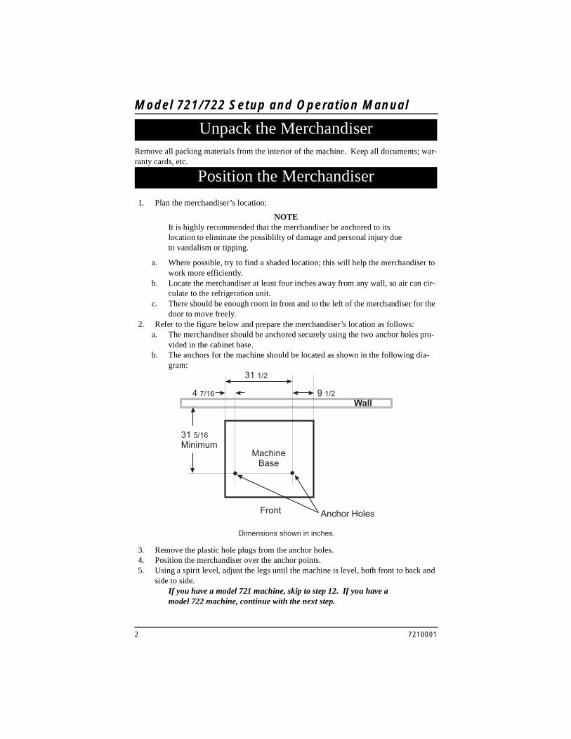
2. Refer to the figure below and prepare the merchandiser’s location as follows:a. The merchandiser should be anchored securely using the two anchor holes pro-
vided in the cabinet base.b. The anchors for the machine should be located as shown in the following dia-
gram:
3. Remove the plastic hole plugs from the anchor holes.4. Position the merchandiser over the anchor points.5. Using a spirit level, adjust the legs until the machine is level, both front to back and
side to side.If you have a model 721 machine, skip to step 12. If you have a model 722 machine, continue with the next step.
Unpack the Merchandiser
Position the Merchandiser

Model 721/722 Setup and Operation Manual
7210001 3
6. Be sure the machine is located on a smooth, level surface. Any cracks or depres-sions in the surface must be filled in.
7. Remove the backing from the double sided tape on one side of the cabinet base seal - included with all model 722 vendors.
NOTEThe double sided tape on the cabinet base seal will be attached to the base along the SIDES of the machine, NOT the back and front.
NOTEDo not lift the machine using the inside trays or the refrigeration shelf.
8. Using the appropriate equipment (appliance dolly), lean the machine to one side far enough to place the cabinet base seal under the machine. Secure the cabinet base seal to the raised side of the base. Push the cabinet base seal under the front and rear of the machine as far as it will go.
9. Gently lower the machine to the ground and lean it in the other direction.10. Remove the backing from the double sided tape on the other side of the seal.
Arrange the cabinet base seal all around the base of the cabinet and secure the cabi-net base seal to the raised side of the machine.
11. Gently lower the machine to the ground. The base seal should be even all around the cabinet base without wrinkles or stretched areas.
12. Anchor the merchandiser using the two lag screws and fender washers. DO NOT overtighten the screws; tighten them enough to prevent movement of the machine.

Model 721/722 Setup and Operation Manual
4 7210001
13.
1. Place A Tray In The Loading Positiona. Put both hands on the tray as shown.b. Push down on the tray latches with your thumbs.c. Pull the tray toward you until you hear and feel the rear tray rollers drop into a
cut-out in the top of the guide rail.
d. Continue pulling the tray forward for another inch. You will then be able to tilt the tray downward into the loading position as shown.
Loading the Merchandiser
PULL
TRAYLATCH
TRAYLATCH
157P0011

Model 721/722 Setup and Operation Manual
7210001 5
2. Set Up Trays to Vend ProductsThese instructions will guide you through setting up your trays for vending. You will be asked to determine if your tray can physically hold the products you intend to vend. If not, you will be directed to other procedures which will help you get them set up. Follow these steps for each tray in your machine:
a. Make sure the tray is in the loading position.b. Is the column wide enough for the intended product? If so, proceed to the next
step. Otherwise, set up your tray to vend wider products (below). When you’re done, return to step c in this procedure.
c. Will the products fit between the spiral turns? If so, proceed to the next step. Otherwise, change the spiral.
d. Will the product pass under the tray immediately above? If so, proceed to the next step. Otherwise, reposition the tray and guides.
e. Will the product touch products on either side? If not, proceed to the next step. Otherwise, install a product spacer.
f. Load products in the tray.g. Return the tray to the vending position.h. Install the price rolls.i. Install the selection ID numbers.
3. Set Up A Tray To Vend Wide ProductsThe following steps will help you configure your tray to vend wide products. When you have completed the procedures called out in each step, return to the next step in the proce-dure. When you are done with the entire wide product steps, return to the set-up proce-dures above.
a. Remove the tray from the merchandiser and place on a flat surface.b. Based on the size of the product you want to vend, decide how many spiral posi-
tions it will occupy. Please remember that the leftmost spiral in the group must have an even ID number (0, 2, 4, etc.) For example, if a product is three spirals wide, the left spiral will be ID number 0, and the right spiral will be ID number 2. Be careful how wide you set up for, because really wide products could get hung up in the delivery door.
c. Remove the column dividers inside the group. In the example of three spiral positions, you would be removing the dividers between spiral ID numbers 0 and 1, and 1 and 2.
d. If your group only consists of two spirals, replace the rightmost motor with a spiral bearing and gear, and install a gear on the leftmost motor. Skip to step 8.
e. Remove all spirals in the group except the leftmost spiral.f. Do one of the following:
• If your group has an ODD number of spirals (3, 5, etc.) remove the harnesses from all motors in the group except the leftmost one. To the rightmost motor, connect the harness from the motor immediately to its left.
• If your group has an EVEN number of spirals (4, 6, etc.) remove the har-nesses from all motors inside the group (leave the harnesses connected to the leftmost and rightmost motors).

Model 721/722 Setup and Operation Manual
6 7210001
g. Install a spiral at the rightmost position in your group. Make sure it has the same product capacity and is opposite to the one in the leftmost position.
h. Return the tray to the merchandiser.i. Electronically couple the motors as needed (see your Programming Guide for
information).j. Return to step c in the Set Up Trays to Vend Products procedure (page 5).

Model 721/722 Setup and Operation Manual
7210001 7
4. Removing a Tray
PC BOARDATTACHED TOTRAY GUIDE
TRAY GUIDE RAIL
PULL
TRAYLATCH
TRAYLATCH
157P0011
Study this procedure before you install a tray for the first time; while you are holding the tray you will not be able to see this area. Proceed as follows:
a. Push down on the tray latches with your thumbs.
c. Unplug the tray wiring har-ness from the PC board mounted on the tray guide rail JUST ABOVE the tray you are removing.
TRAYLATCH
TRAYGUIDERAIL
157P0027
b. Pull the tray forward until you hear and feel the rear tray roll-ers drop into a cut-out in the top of the guide rail.

Model 721/722 Setup and Operation Manual
8 7210001
TRAYROLLER
TRAYGUIDERAIL
REAR OF TRAY
d. Lift up on the tray and slide it toward the back. No more than an inch should be needed.
e. The tab near the back of the tray should align with the cut-out in the top of the guide rail as shown.
f. Lift the tray clear of the guide rail and out of the merchandiser.
CUT-OUT
TAB(ON TRAY)
REAR OFTRAY
TRAY GUIDERAIL
5. Removing And Installing Column Dividersa. Push the column divider toward the
back of the tray - .
b. Lift the column divider clear of the
tray - .
Install the column divider in the reverse order of removal
1
2
2
1
COLUMNDIVIDER

Model 721/722 Setup and Operation Manual
7210001 9
.
Tray harness extension (P/N 1709017) is available from your National Vendors Parts department. The extension will enable you to remove the tray from the machine and still operate the motors and spirals. Connect it as shown:
Operate a Tray Outside the Machine

Model 721/722 Setup and Operation Manual
10 7210001
.
1. Replacing a Motor With a Spiral Bearing
REMOVING A MOTOR:
a. Disconnect the harness from the motor. See CONNECTING AND DISCON-NECTING A MOTOR HARNESS, below.
b. Remove the spiral. See REMOVING AND INSTALLING SPIRALS (page 11).
c. Remove the spiral coupler. See REMOVING A SPIRAL COUPLER (page 13).d. Remove the motor. See REMOVING AND INSTALLING A SPIRAL
MOTOR (page 13).
INSTALLING A SPIRAL BEARING:
a. Put the gear into position if required in this set-up as shown. See INSTALLING A GEAR (page 14).
Install the spiral coupler. See INSTALLING A SPIRAL COUPLER (page 15).
Changing Tray Configurations
SPIRALBEARING
GEAR
SPIRALCOUPLER
BACKWALLOF TRAY
˜
MOTOR
MOTORHARNESS
2. Connecting and Disconnecting a Motor HarnessTo avoid breaking the motor circuit board, hold the header on the circuit board when-ever connecting or disconnecting a motor harness.
DISCONNECTING A MOTOR HARNESS:
a. Pull the harness connector away from the circuit board as shown.
b. Tuck the unused part of the harness out of the way in the trough at the back of the tray.
CONNECTING A MOTOR HARNESS:
a. Locate the harness connector for the appropriate tray position.Push the harness connector over the header pins on the motor circuit board as shown.

Model 721/722 Setup and Operation Manual
7210001 11
3. Removing and Installing SpiralsAll spirals are the same diameter:
• There are two types of spirals:
• Spirals are available in eight different capacities. Four of these are standard, and four are options.
ITEM CAPACITY OF SPIRAL
PART NUMBER
CLIP COLORCLOCKWISE (RH)
COUNTERCLOCKWISE (LH)
6 (Optional) 1477104 1477102 Purple
11 (Standard) 1477027 1477024 Blue
13 (Standard) 1477033 1477030 Yellow
15 (Standard) 1477039 1477036 Red
20 (Standard) 1477045 1477042 White
25 (Optional) 1477051 1477048 Green
30 (Optional) 1477057 1477054 Black
38 (Optional) 1477063 1477060 Orange
COUNTER-CLOCKWISE (left hand) CLOCKWISE (right hand)

Model 721/722 Setup and Operation Manual
12 7210001
TO REMOVE A SPIRAL:
a. Pull forward on the retaining clip and remove the end of the spiral from the spi-ral coupler as shown.
b. Remove the spiral from the tray.
TO INSTALL A SPIRAL:
a. Pull the bottom of the retaining clip toward the front of the spiral.b. Lower the spiral into the tray column and insert the end of the spiral into the spi-
ral coupler as shown.c. Release the retaining clip.
SHOULD I USE A CLOCKWISE OR A COUNTERCLOCKWISE SPIRAL?
a. The type of spiral used is determined by the column position it will occupy in the tray.
b. Refer to the figure below to find the correct spiral type.
PULL
LIFT
SPIRALRETAINING
CLIP
SPIRALCOUPLER
A8 A9A0 A1 A2 A3 A4 A5 A6 A7
Model 721/722 Setup and Operation Manual
7210001 13
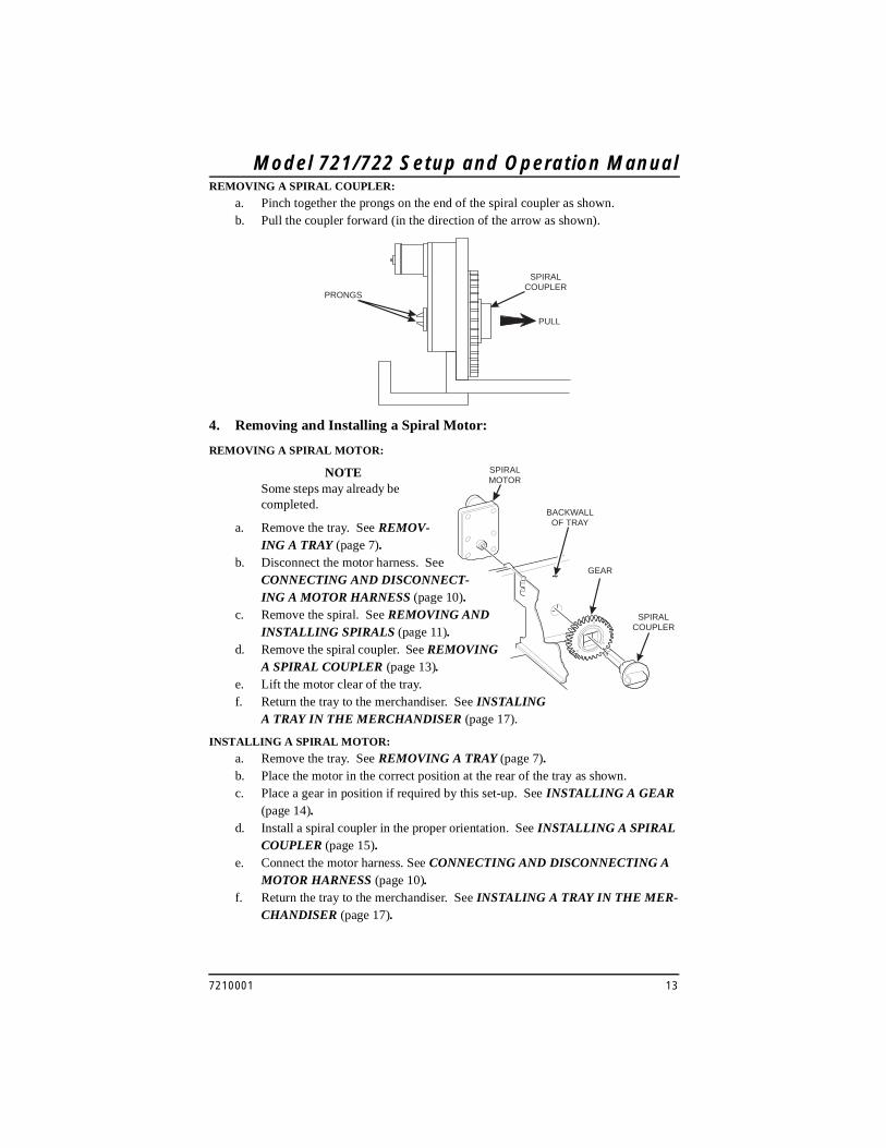
REMOVING A SPIRAL COUPLER:
a. Pinch together the prongs on the end of the spiral coupler as shown.b. Pull the coupler forward (in the direction of the arrow as shown).
PRONGS
SPIRALCOUPLER
PULL
GEAR
SPIRALCOUPLER
BACKWALLOF TRAY
˜
SPIRALMOTOR
4. Removing and Installing a Spiral Motor:
REMOVING A SPIRAL MOTOR:
NOTESome steps may already be completed.
a. Remove the tray. See REMOV-ING A TRAY (page 7).
b. Disconnect the motor harness. See CONNECTING AND DISCONNECT-ING A MOTOR HARNESS (page 10).
c. Remove the spiral. See REMOVING AND INSTALLING SPIRALS (page 11).
d. Remove the spiral coupler. See REMOVING A SPIRAL COUPLER (page 13).
e. Lift the motor clear of the tray.f. Return the tray to the merchandiser. See INSTALING
A TRAY IN THE MERCHANDISER (page 17).
INSTALLING A SPIRAL MOTOR:
a. Remove the tray. See REMOVING A TRAY (page 7).b. Place the motor in the correct position at the rear of the tray as shown.c. Place a gear in position if required by this set-up. See INSTALLING A GEAR
(page 14).d. Install a spiral coupler in the proper orientation. See INSTALLING A SPIRAL
COUPLER (page 15).e. Connect the motor harness. See CONNECTING AND DISCONNECTING A
MOTOR HARNESS (page 10).f. Return the tray to the merchandiser. See INSTALING A TRAY IN THE MER-
CHANDISER (page 17).

Model 721/722 Setup and Operation Manual
14 7210001
5. Installing a Gear
WHEN ARE GEARS USED?
• Gears are used to mechanically couple the spirals together.
• This happens whenever you have two spirals and only one motor for vending a selec-tion.
WHERE ARE THE GEARS PLACED?
• The gear is placed between the back of the tray and the spiral coupler.
HOW IS THE GEAR ORIENTED?
• There are two possible orientations for the gear:
• There are two rules to follow when orienting gears:
RULE 1 - The gears for selections next to each other cannot use the same ori-entation.
RULE 2 - All gears for a single selection must use the same orientation.
BACK WALLOF TRAY
GEAR
ORIENTATION 1 ORIENTATION 2

Model 721/722 Setup and Operation Manual
7210001 15
SPIRAL COUPLER ORIENTATION
WHEN USED WITH A COUPLER BEARING:c. Hold the coupler bearing in place and push the spiral coupler through the bear-
ing until the coupler clicks into position. Be sure the coupler is in the proper ori-entation as shown.
MOTOR
SPIRALCOUPLER
FRONT VIEW OFMOTOR OUTPUT SHAFT
6. Installing a Spiral Couplera. Place the gear in position if one is required for this set-up. See INSTALLING A
GEAR (page 14).WHEN USED WITH A MOTOR:
b. Hold the motor in place and push the spiral coupler through the motor gear box until it clicks into position. Be sure the spiral couplers are ori-ented as shown below.
NOTEThe motor output shaft opening contains eight facets to allow the spiral coupler to be installed in any one of eight posi-tions.
LEFT SPIRALCOUPLER
RIGHT SPIRALCOUPLER
AS VIEWED FROM FRONT OF TRAY
ONE POSITIONCOUNTERCLOCKWISE
FROM VERTICAL
ONE POSITIONCLOCKWISE
FROM VERTICAL
SPIRALCOUPLER
SPIRALBEARING

Model 721/722 Setup and Operation Manual
16 7210001
7. Moving a Tray Up or DownThis merchandiser can be adjusted to vend taller products. Some guidelines must be fol-lowed:• Keep in mind that when you increase the product height available to a tray by lower-
ing it, you will be decreasing the product height available to the tray below.
• If a tray is in the lowest position, the tray below it should not be in the highest posi-tion.
• If a tray is in the highest position, the tray above it should not be in the lowest posi-tion.
• You will need to experiment with various tray positions to get the best results for your products.
CAUTIONTrays should not be positioned over an open air discharge vent.
NOTETray movement is limited because the tray harness will limit the amount of travel available to the tray guide rails.
SCREW
CHANNELSLOT
FRONT GUIDEMOUNTING CHANNEL
REAR GUIDEMOUNTING CHANNEL
TRAYGUIDERAIL
PC BOARD
Proceed as follows:a. Remove the tray from the merchandiser. See REMOVING A TRAY (page 7).b. Remove the screw that secures the right tray guide rail to the front guide mount-
ing channel as shown.c. Tap up on the guide rail and unseat the guide rail tabs from the channel slots.d. Pull the guide rail away from the front and rear guide mounting channels.e. Move the guide rail to the desired position.f. Insert the guide rail tabs into the mounting CVchannel slots as shown.g. Tap down on the guide rail to seat the tabs in the channel slots.h. Replace the screw that secures the
guide rail to the front guide mounting channel.
i. Repeat steps b through h for the left guide rail.
j. Return the tray to the merchandiser. See INSTALLING A TRAY IN THE MERCHAN-DISER (page 17).
k. Load products into the trays, and perform test vends. Make sure the trays don't interfere with the products you are vending, and that all products vend properly.
Model 721/722 Setup and Operation Manual
7210001 17
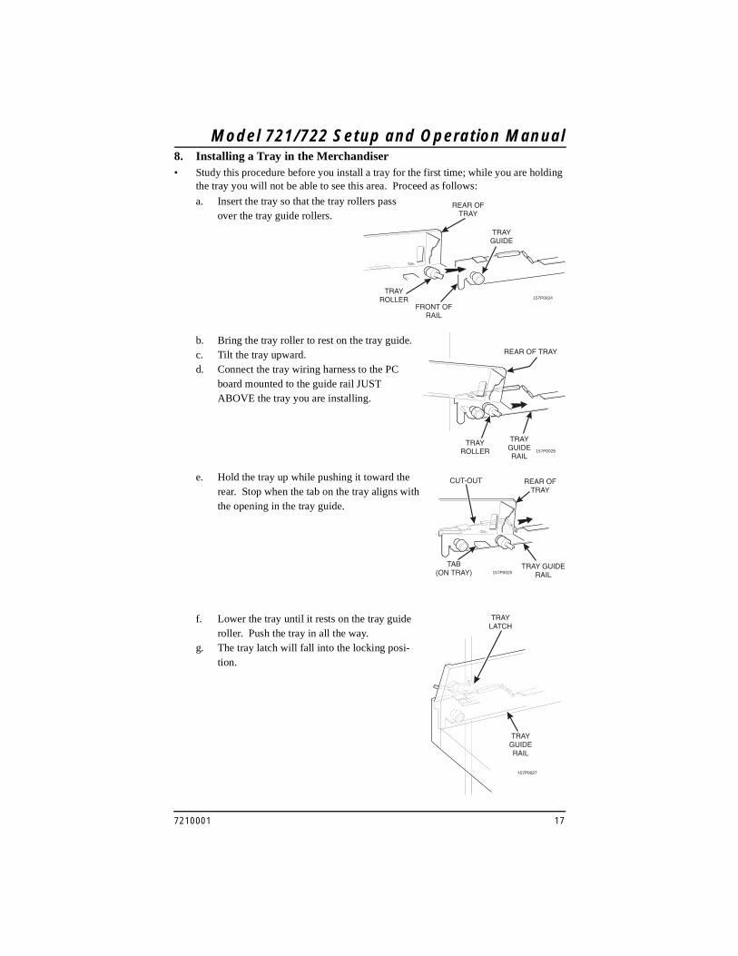
8. Installing a Tray in the Merchandiser• Study this procedure before you install a tray for the first time; while you are holding
the tray you will not be able to see this area. Proceed as follows:
TRAYROLLER
TRAYGUIDE
REAR OFTRAY
FRONT OFRAIL
157P0024
a. Insert the tray so that the tray rollers pass over the tray guide rollers.
b. Bring the tray roller to rest on the tray guide.c. Tilt the tray upward.d. Connect the tray wiring harness to the PC
board mounted to the guide rail JUST ABOVE the tray you are installing.
TRAYROLLER
TRAYGUIDERAIL
REAR OF TRAY
157P0026
e. Hold the tray up while pushing it toward the rear. Stop when the tab on the tray aligns with the opening in the tray guide.
CUT-OUT
TAB(ON TRAY)
REAR OFTRAY
TRAY GUIDERAIL157P0025
f. Lower the tray until it rests on the tray guide roller. Push the tray in all the way.
g. The tray latch will fall into the locking posi-tion.
TRAYLATCH
TRAYGUIDERAIL
157P0027

Model 721/722 Setup and Operation Manual
18 7210001
9. Installing and Removing a Product Spacer
INSTALLING A PRODUCT SPACER:
a. Insert the product spacer mounting pins into the column divider as shown.
ADJUSTING A PRODUCT SPACER:
a. With product loaded in the tray, rotate the product spacer up or down to keep the product upright as shown.
REMOVING A PRODUCT SPACER:
a. Pull the product spacer mounting pins from the column divider.
PRODUCTSPACER
COLUMNDIVIDER
MOUNTINGPINS
MOUNTINGPINS
Model 721/722 Setup and Operation Manual
7210001 19
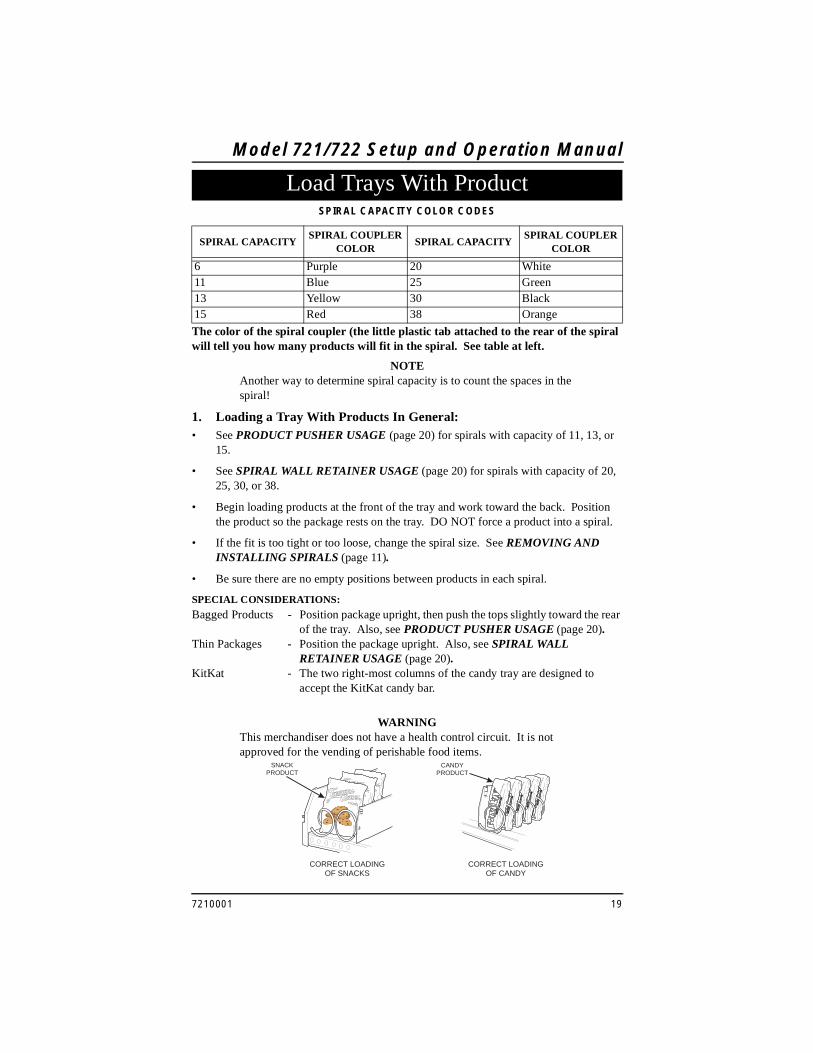
The color of the spiral coupler (the little plastic tab attached to the rear of the spiral will tell you how many products will fit in the spiral. See table at left.
NOTEAnother way to determine spiral capacity is to count the spaces in the spiral!
1. Loading a Tray With Products In General:• See PRODUCT PUSHER USAGE (page 20) for spirals with capacity of 11, 13, or
15.
• See SPIRAL WALL RETAINER USAGE (page 20) for spirals with capacity of 20, 25, 30, or 38.
• Begin loading products at the front of the tray and work toward the back. Position the product so the package rests on the tray. DO NOT force a product into a spiral.
• If the fit is too tight or too loose, change the spiral size. See REMOVING AND INSTALLING SPIRALS (page 11).
• Be sure there are no empty positions between products in each spiral.
SPECIAL CONSIDERATIONS:
Bagged Products - Position package upright, then push the tops slightly toward the rear of the tray. Also, see PRODUCT PUSHER USAGE (page 20).
Thin Packages - Position the package upright. Also, see SPIRAL WALL RETAINER USAGE (page 20).
KitKat - The two right-most columns of the candy tray are designed to accept the KitKat candy bar.
WARNINGThis merchandiser does not have a health control circuit. It is not approved for the vending of perishable food items.
SPIRAL CAPACITY COLOR CODES
SPIRAL CAPACITYSPIRAL COUPLER
COLORSPIRAL CAPACITY
SPIRAL COUPLER COLOR
6 Purple 20 White11 Blue 25 Green13 Yellow 30 Black15 Red 38 Orange
Load Trays With Product
SNACKPRODUCT
CANDYPRODUCT
CORRECT LOADINGOF SNACKS
CORRECT LOADINGOF CANDY

Model 721/722 Setup and Operation Manual
20 7210001
PRODUCTPUSHER
2. Spiral Wall Retainer Usage:A spiral wall retainer serves to compress the spiral and make it act like a spring to more forcefully eject a product. Do some test vends and use a spiral wall retainer when a product does not readily leave the spiral.• Use a spiral wall retainer in the following cases:
- The spiral has a capacity of 20, 25, 30, or 38.
- The product is thin.
- The product is on a candy tray.
• The spiral wall retainer can also be used with other spirals and types of products.
• The spiral wall retainer is installed near the front of the column divider.
• There are two ways to install the spiral wall retainer.
• To install a spiral wall retainer, insert the retainer in the square slot near the front of the column divider.
• The spiral wall retainer must be removed in two cases:
- A Kit-Kat bar loaded into either of the two right hand positions of a tray will not clear the retainer on the column divider between the two positions.
- A product pusher will catch on a retainer in ORIENTATION A.
3. Product Pusher Usage:The product pusher will give the top of a product an extra tilt to help it fall into the delivery pan.Use a product pusher in the following cases:
• The spiral has a capacity of 15, 13, or 11.
• The package is non-rigid like bagged peanuts
The product pusher can also be used with other spiral and types of products.
A bag of product pushers has been shipped with the merchandiser. Additional product pushers are available from the National Vendors' parts department. To use a product pusher, snap it on the spiral as shown. You can adjust the product pusher by moving it around on the spiral to achieve the best vending results.
RETAINER ORIENTATION
A B
COLUMN DIVIDER
BETWEEN THESE
POSITIONS
0 and 1 1 and 2
2 and 3 3 and 4
4 and 5 5 and 6
6 and 7 7 and 8
8 and 9
SPIRALWALL
RETAINER
ORIENTATION A
DIVIDER
ORIENTATION B

Model 721/722 Setup and Operation Manual
7210001 21
4. Preparing the Merchandiser for Vending "Lunch Bucket":Because of the weight and shape of the pack-age, National Vendors recommends that this product be vended only from the bottom tray.
To vend this product, two adjacent positions must be coupled together.
See INSTALLING A GEAR (page 14), for mechanical coupling directions, or see the Programming Guide for electrical coupling direc-tions.
The left spiral coupler should be installed one position counterclockwise from the vertical position.
The right spiral coupler should be installed one position clockwise from the vertical posi-tion.
Replace the current spirals with six-count spirals. These are available from the National Vendors parts department. See REMOVING AND INSTALLING SPIRALS (page 11).
A pad can be installed in the bottom of the delivery pan to quiet and cushion product deliv-ery. This part is available from the National Vendors parts department.
Load "Lunch Bucket" products as shown.
FOOD SELECTIONSLOADED IN SPIRALS
157P0039
LEFT SPIRALCOUPLER
RIGHT SPIRALCOUPLER
AS VIEWED FROM FRONT OF TRAY
ONE POSITIONCOUNTERCLOCKWISE
FROM VERTICAL
ONE POSITIONCLOCKWISE
FROM VERTICAL

Model 721/722 Setup and Operation Manual
22 7210001
5. Preparing the Merchandiser for Vending "Top Shelf":National Vendors recommends that “Top Shelf” product be vended from a candy tray.
Move the tray so the package can be loaded standing on its left or right edge. See MOV-ING A TRAY UP OR DOWN (page 16).
The following steps must be completed for three adjacent positions on the tray:
NOTEThe left-most position in the group of three must be an even numbered position.
Couple the left motor to the right motor. See the Programming Guide.
Load the "Top Shelf" products as shown.
Correct Loading Of "Top Shelf"
1. REMOVE COLUMNDIVIDERS
2. REMOVESPIRALS
7. INSTALL AN 11-COUNT LEFT HANDSPIRAL IN THIS POSITION
INSTALL AN 11-COUNT RIGHT-HANDSPIRAL IN THIS POSITION
8.
157P0040
4.DISCONNECT THIS
MOTOR CONNECTOR
3.LEAVE THIS MOTORCONNECTOR ALONE
5.MOVE CONNECTORFROM THIS MOTOR
6.TO THIS MOTOR
TOP SHELFPRODUCT

Model 721/722 Setup and Operation Manual
7210001 23
.
a. Lift the tray until it is parallel to the floor as shown.
b. Push the tray toward the back of the cabinet. The tray latches on the sides of the tray will lock into position.
Return the Trays to the Vending Position
PULL
TRAYLATCH
TRAYLATCH
157P0011
TRAYLATCH
TRAYGUIDERAIL
157P0027

Model 721/722 Setup and Operation Manual
24 7210001
Install and Set Price Labels• Price rolls are printed on coiled-up strips as
shown in this example. (The dollar and cents rolls are factory installed.) If you use another type of currency, you will find the appropriate price rolls in the plastic bag that contained this manual.
• There are two types of price rolls installed:
Dollar roll - 1 to 12, increments of 1Cents roll - 00 to 95, increments of 05
• Remove the price rolls as required, and install the appropriate one(s) for your cur-rency.
1. Installing Price Labels:• There are three pairs of slots in the
front of the tray for each position. Install per this example:
a. Insert the dollar roll in the left-most pair of slots as shown if the price is $1.00 or more.
b. Insert the cents roll in the center pair of slots as shown.
c. The low-number end of the roll goes in the top slot and the high-number end of the roll goes in the bottom slot.
2. Adjusting the price roll:You can set selection prices within the following range:
Minimum price $.00Maximum price $12.95Increment $.05
a. Use your thumb as shown to move each price roll up or down as needed to set the desired price.
NOTE
You will see the word STOP near
either end of the roll.
CENTS ROLL
DOLLAR ROLL
157P0043
PRESS TOP OF ROLLPAST FLEXIBLE TABNEAR TOP EDGE
INSERT BOTTOM OF ROLLTHROUGH SLOT ALONGBOTTOM EDGE
157P0044
157P0045

Model 721/722 Setup and Operation Manual
7210001 25
Selection ID numbers are printed on clear plastic sheets. You will find these in the plastic bag that contained this manual. You will need to separate them along the scored lines between the selections. BE CAREFUL when doing this, because it is easy to split the labels.
1. Installing Selection ID Numbers:a. Press together the two long edges of the selection ID label.b. Snap the selection ID label into position on the front of the tray as shown.
Install Selection ID Labels
SELECTIONIDENTIFICATION LABEL
CENTSPRICE ROLL
DOLLARPRICE ROLL
SELECTIONIDENTIFICATION
157P0059

Model 721/722 Setup and Operation Manual
26 7210001
2. Which ID Label Goes With Which Selection?See the figures below for snack and candy tray positions.
NOTEThis example shows a 3-tray merchandiser.
MOTOR POSITION
TOP TRAY TRAY A A0 A1 A2 A3 A4 A5 A6 A7 A8 A9
TRAY B B0 B1 B2 B3 B4 B5 B6 B7 B8 B9
BOTTOM TRAY TRAY C C0 C1 C2 C3 C4 C5 C6 C7 C8 C9
A0 A2 A4 A6 A8
A8 A9A0 A1 A2 A3 A4 A5 A6 A7
EXAMPLE OF A BASIC SNACK TRAY ID LABEL TO USE
EXAMPLE OF A BASIC CANDY TRAY ID LABEL TO USE
Model 721/722 Setup and Operation Manual
7210001 27
1. Connect a Refrigeration Module to an External Drain (Optional)a. Connect a drain tube to the condensate pan.b. Route the drain tube to an external drain or to an overflow bucket.
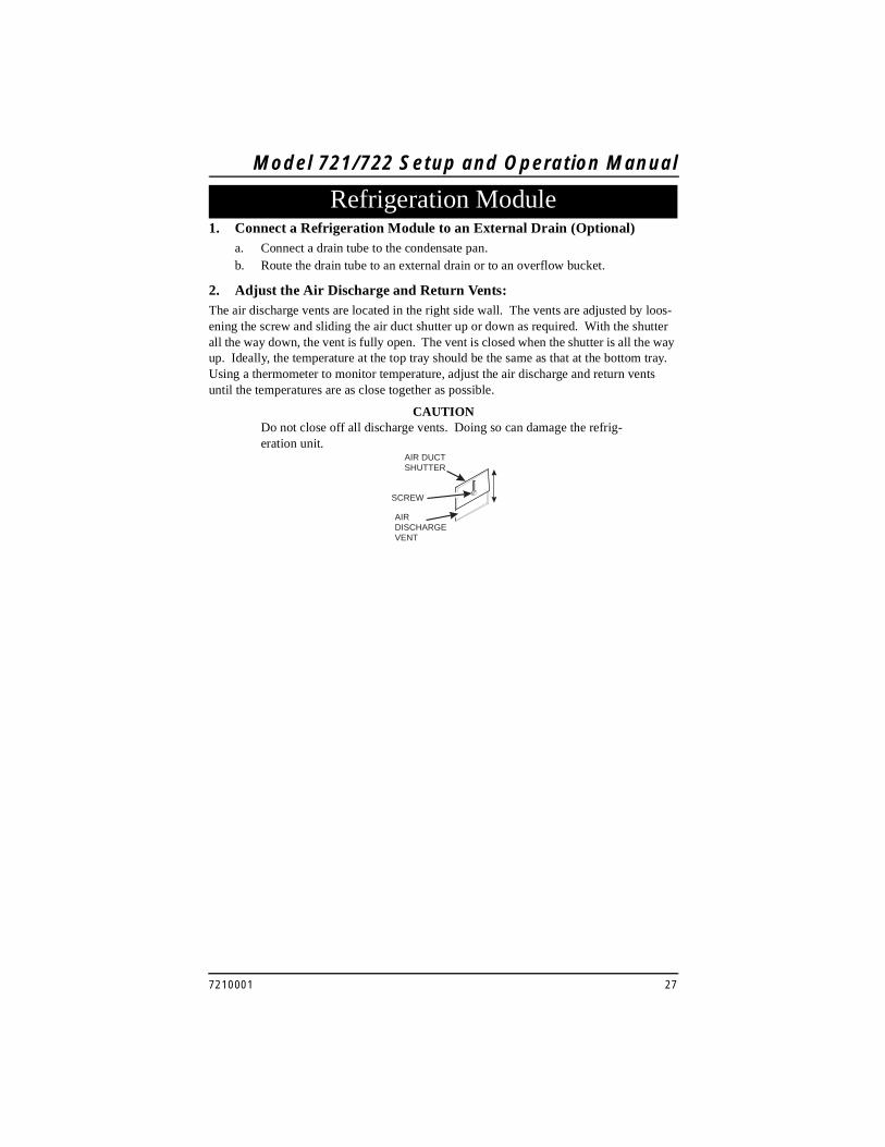
2. Adjust the Air Discharge and Return Vents:The air discharge vents are located in the right side wall. The vents are adjusted by loos-ening the screw and sliding the air duct shutter up or down as required. With the shutter all the way down, the vent is fully open. The vent is closed when the shutter is all the way up. Ideally, the temperature at the top tray should be the same as that at the bottom tray. Using a thermometer to monitor temperature, adjust the air discharge and return vents until the temperatures are as close together as possible.
CAUTIONDo not close off all discharge vents. Doing so can damage the refrig-eration unit.
Refrigeration Module
AIR DUCTSHUTTER
SCREW
AIRDISCHARGEVENT

Model 721/722 Setup and Operation Manual
28 7210001
1. Install the Lock Cylinder:Install an optional lock cylinder in the merchandiser as follows:
a. Position the lift handle lock lever as shown.b. Depress the lock spring at the square hole of the lock cylinder receptacle and
pull the lock springs out through the front.c. Position the lock cylinder as shown. Depress the spring loaded lock pin.d. Push the cylinder into the cylinder receptacle in the lever. The pin should snap
into the square hole.e. If the cylinder pin does not seat in the square hole, press against both ends of the
lock cylinder. Rotate the cylinder until the pin snaps into place.f. Leaving the door open, test the lock mechanism with a key.
2. Install the Optional Cash Box Lock:a. Remove the cash box from the merchandiser.b. Assemble the lock as shown in the illustration to the right.c. Return the cash box to the merchandiser.
3. Load the Coin Mechanism:a. Open the cabinet door.b. Open the monetary door.c. Insert coins one at a time until each of the coin tubes has been filled.d. Inspect the tubes for shingled coins and correct if necessary.
Accessories
LOCK BAR
SCREW
NUT
WASHERLOCKCYLINDER

Model 721/722 Setup and Operation Manual
7210001 29
1. Set Prices
a. Press . The display shows ** 2.50 .25. This display shows the
maximum and minimum prices set in the machine. In this example, the maxi-mum price is $2.50 and the minimum is $0.25.
b. Press the number of the selection to be priced. (Example: B1.) The display
shows B1 X.XX . Enter a price using the number keys. The selection is now
priced.
c. Press another letter key, or to price another selection.
Basic ProgrammingThe service keypad (shown on the left) is your major tool to program your merchandiser. If you just need to get your merchandiser up and running, you only have to set prices. That procedure is given below. For a thorough explanation of how to do all the custom programming features available to you, consult your Programming Guide. It will tell you how to:• Set up custom time-of-day vending periods;• Look at sales and vending data;• Test various machine functions;• Customize trays for vending unique products;• Enter custom display messages;• And much more!
Service Keypad

Model 721/722 Setup and Operation Manual
30 7210001
2. View the Cabinet Temperature
a. Press . Depending on how your machine is configured, the display will
show, for example, TEMP 66 ° F. This example shows that the temperature is 66
degrees Farenheit.b. If you need to change the cabinet temperature setting, refer to your Program-
ming Manual.
c. To change the display units, press . The display now shows
TEMP 19 ° C.
d. An I replacing the F or C means a sensor error exists and the displayed temper-ature is invalid. A decimal point in the display means the compressor is run-ning; an apostrophe means the heater is on.
NOTEWhen the machine door is closed, you can view the temperature by
pressing on the selection panel.
e. Press until you have left the function.

Model 721/722 Setup and Operation Manual
7210001 31
Now, you have connected your merchandiser to the utilities, placed it in its final location, loaded it with products, and set the prices. Before you lock the door and move on, you should check to see if your merchandiser will vend products. In case of problems, perform the operational readiness checks beginning on the next page.
1. Test Vend Selections
a. Press . The display shows TEST .00. You may now test vend selec-
tions. If you insert money into the machine, the zeros in the display will be replaced with the amount of the credit. After the item vends, your money will be returned.You may make one more test vend if you close the door while still in TEST VEND mode.
b. Press until you have left the function.
2. Operational Readiness Checka. Perform test vends on all selections.b. Do any of the snack or candy products catch on the tray and fail to vend? If not,
skip to step c. If so, perform the following procedures on the affected areas until all products vend properly:1. Install and/or adjust a product spacer.2. Install a product pusher.3. Install and/or remove spiral wall retainers.4. Perform the appropriate spiral anti-hang-up procedure(s) (see below).
c. Test the operation of the coin mechanism (see the Programming Guide for the proper procedure.).
d. Test the operation of the bill validator.e. Return all test vended products to the trays.
Final Checkout

3. Spiral Indexing Procedure (One Spiral, One Motor)The spiral indexing procedures involve rotating spirals one position at a time until the product vends properly.
a. Home all the motors (see the Programming Guide).b. Remove the affected spiral.c. Is the coupler in the proper position?
NO - Move the coupler to the position as shown in INSTALLING A SPIRAL COUPLER (page 15). Go to step d.YES - Move the coupler to the next clockwise position (if it’s on a right-hand motor), or the next counterclockwise position (if it’s on a left-hand motor). Go to step d.
d. Replace the spiral.e. Perform a test vend (see page 31).f. Did the product hang up?
NO - You’re finished. Continue to test vend the remaining selections until everything works right.YES - Go to step g.
g. Did you previously move the coupler to the next clockwise or counterclockwise position?NO - Move the coupler to the next clockwise position (if it’s on a right-hand motor), or the next counterclockwise position (if it’s on a left-hand motor). Return to step 6.YES - Return to step b in the operational readiness check (see page 31) and try another procedure. Do not move the coupler again.

Model 721/722 Setup and Operation Manual
7210001 33
4. Spiral Indexing Procedure (Two Spirals, One Or Two Motors)The spiral indexing procedures involve rotating spirals one position at a time until the product vends properly.
a. Home all the motors (see the Programming Guide).b. Remove the left hand spiral of the affected pair.c. Is the coupler in the proper position?
NO - Move the coupler to the position as shown in INSTALLING A SPIRAL COUPLER (page 15). Go to step d.YES - Move the left coupler to the next counterclockwise position. Go to step d.
d. Replace the left hand spiral.e. Remove the right hand spiral, spiral coupler, and gear (if used) of the affected
pair as a unit.f. Rotate this unit until the right hand spiral mirrors the position of the left hand
spiral.g. Replace the right hand spiral, spiral coupler, and gear (if used).h. Perform a test vend (see page 31).i. Did the product hang up?
NO - You’re finished. Continue to test vend the remaining selections until everything works right.YES - Go to step j.
j. Did you previously move the left hand coupler to the next counterclockwise position?NO - Remove the left hand spiral of the affected pair. Turn the left spiral cou-pler to the next counterclockwise position. Return to step 4.YES - Return to step b in the operational readiness check (see page 31) and try another procedure. Do not move the coupler again.
5. Testing the Bill Validatora. Insert a $1 bill into the validator.b. Push the coin return button.
THE BILL VALIDATOR IS IN THE ESCROW MODE - No money is returned - you must make a selection in order to receive any change. Go to step c.THE BILL VALIDATOR IS NOT IN THE ESCROW MODE - You should receive four quarters in change. Go to step c.
c. Make a selection. the correct selection should be vended and correct change should be returned.

Model 721/722 Setup and Operation Manual
34 7210001
Notes . . .

This Merchandiser is warranted for one (1) year against defective parts and workmanship. Any part or parts which are proven to be defective within one (1) year of the date of ship-ment will be repaired or replaced free of charge when the defective part is returned, with transportation charges prepaid, to the destination designated by the National Vendors War-ranty Department.
This warranty applies only to the original purchaser of the Merchandiser and is null and void if the Merchandiser is sold during the period of warranty.
This warranty does not apply to a) electrical components, wiring, or circuits and/or for all mechanical parts or assemblies damaged as a result of operating the Merchandiser at other than the design voltage and frequency specified on the Electrical Rating Tag, or b) in event of vandalism, fire or negligence, or c) incandescent lamps, neon lamps, fluorescent lamps, ballasts, starters or other expendable items or d) when other manufactured compo-nents are installed in National Vendors Merchandisers.
National Vendors is not responsible for any cost of service rendered or repairs made by customer or its agents on Merchandiser or parts unless authorization to incur such expense has been given in writing by National Vendors prior to incurring such expense.
THIS WARRANTY IS IN LIEU OF ALL OTHER WARRANTIES EXPRESSED OR IMPLIED, INCLUDING WITHOUT LIMITATION, WARRANTIES OF MERCHANTABILITY OR FITNESS FOR A PARTICULAR PURPOSE. NATIONAL VENDORS SHALL NOT BE RESPONSIBLE FOR CONSEQUENTIAL OR PUNITIVE DAMAGES. National Vendors neither assumes nor authorizes any person to assume for it any obligation or liability in connection with the sale of said equipment or any part thereof.
National VendorsA Division of CRANE CO12955 Enterprise WayBridgeton, MO 63044
