and wear in the blast furnace crucible … · crucibles, bottom, walls and roofs of electric...
TRANSCRIPT

A R C H I V E S O F M E T A L L U R G Y A N D M A T E R I A L S
Volume 55 2010 Issue 4
DOI: 10.2478/v10172-010-0014-4
R. GONZALEZ∗, M. A. BARBES∗∗, L. F. VERDEJA∗∗, I. RUIZ-BUSTINZA∗∗∗, J. MOCHÓN∗∗∗, R. M. DUARTE∗∗∗, M. KARBOWNICZEK∗∗∗∗
THE NODAL WEAR MODEL (NWM) AS AN ALTERNATIVE TO UNDERSTAND THE MECHANISMS OF FLOWAND WEAR IN THE BLAST FURNACE CRUCIBLE
WĘZŁOWY MODEL ZUŻYWANIA (NWM) JAKO ALTERNATYWA ZROZUMIENIA MECHANIZMÓWPRZEPŁYWU I ZUŻYCIA WYŁOŻENIA GARU WIELKIEGO PIECA
The presence of thermocouples in the lining of crucibles has become a general practice in the new construction of blastfurnaces. The Nodal Wear Model (NWM) has also emerged as an instrument that, while using experimental data, obtains nodalvariables whose experimental measurement is not possible: global coefficient of pig-iron/refractory heat transfer hpig−iron/lining
g−iand nodal temperature Ti.
Starting from these nodal properties, the wear of the lining or the growth of scabs may be controlled, independently ofthe mechanisms responsible for them. In the same way, the properties and influence zone of the dead man in the hearth of theblast furnace may be calculated, along with those regions where the fluid is allowed to move without any other restrictionsthan the ones of the corresponding viscous flow (raceway hearth region).
Keywords: Blast furnace, hearth, wear, dead man
Obecność termopar w wyłożeniu garu wielkiego pieca, stało się powszechną praktyką w jego nowoczesnych konstrukcjach.Węzłowy Model Zużycia, staje się narzędziem, które korzystając z danych doświadczalnych, uzyskuje zmienne węzłowe,dla których pomiar bezpośredni jest niemożliwy: całkowity współczynnik przenikania ciepła między surówką, a wyłożeniemogniotrwałym hsurwka/wyoenie
g−i oraz temperaturę węzłową Ti.Począwszy od tych własności węzła, zużycie wyłożenia lub powiększanie się narostów, może być kontrolowane, niezależnie
od mechanizmów odpowiedzialnych za ich zachodzenie. W ten sam sposób, mogą zostać wyliczone własności i wpływumartwego koksu w garze wielkiego pieca, wzdłuż obszarów, gdzie ciecz może poruszać się bez ograniczeń innych niż teodpowiadające przepływowi lepkiemu (strefa na poziomie dysz w garze pieca).
1. Introduction
When describing the mechanisms of wear in the lin-ing, and of metal flow around the dead man (inactivecoke) that may be present in the crucible of a blast fur-nace during its work life, the following considerationsand work methods to tackle and try to understand theproblem may be found in specialized references [1-3]:a) These are complex phenomena, in which a great
number of variables take part, so a quantitative es-timation of wear suffered by the materials and ofthe density/intensity of the current lines for the meltalong the operation life of the crucible are difficultto find.
b) On the other hand, it is usual for different corrosionmechanisms to act in parallel, making the evaluationof the participation and importance of each of one ofthem in the wear process of the lining very difficult[4]. Furthermore, the fluid velocities in the crucibleare not homogenous as they depend on the occupa-tion degree (geometry), and characteristics (porosity)and quality of the dead man.
c) Attempts have been made to reproduce and simu-late, at a laboratory scale, the operation conditionsthe hearth of the blast furnace may withstand (withfluid-refractory relative velocities of 0.5 cm/s) anddesign the furnace lining in accordance to the results
∗ SCHOOL OF ENGINEERING. UNIVERSIDAD PANAMERICANA. AUGUSTO RODIN 498, 03920 MEXICO D.F., MEXICO∗∗ SID-MET-MAT RESEARCH GROUP. UNIVERSIDAD DE OVIEDO. ETSIMO. INDEPENDENCIA 13, 33004 OVIEDO, SPAIN∗∗∗ CENTRO NACIONAL DE INVESTIGACIONES METALURGICAS (CENIM/CSIC) AVDA DE GREGORIO DEL AMO, 8. 28040-MADRID, SPAIN∗∗∗∗ AGH UNIVERSITY OF SCIENCE & TECHNOLOGY, FACULTY OF METAL ENGINEERING & INDUSTRIAL COMPUTER SCIENCE, A.MICKIEWICZA AV. 30, 30-059 KRAKOW, POLAND

1114
obtained in samples in contact with corrosive fluids(pig iron and slag).
d) Finally, an attempt is being made to understand themovement of the melt inside the crucible through theuse of room temperature physical models, accompa-nied also by measurements using radioactive tracers
to study the characteristics of the pig iron flux incontact with the dead man in the hearth below thenozzles level. Figure 1 shows a 3D finite elementsimulation of the melt flow, where the complexity ofthe results makes it difficult to estimate wears.
Fig. 1. 3D finite element simulation of melt flow in a dead man hearth, showing mesh and element distribution (a) and fluid velocity (b)
A fact that differentiates the NWM in respect to oth-er practices aimed at understanding this problem, is thatboth wear and scab growth, as well as dead man charac-teristics, circulation velocities of the fluids (pig iron andslag), furnace operation (production) parameters, geo-metric design characteristics and nature of the cruciblematerials, are not independent variables and, the valueseach one of them may reach, slightly or strongly deter-mine all the others. For example, when trying to explainthe behavior of refractory linings submitted to corrosiveaction (pig iron and slag), different wear mechanismsor physical characteristics or geometries the dead manmay adopt inside the hearth are described, as if these re-sults were not a consequence of a determined operation(production) practice, under which, the blast furnace hasbeen demanded to produce for specific periods of time.
The novelty of the NWM is to admit that wear, blastfurnace production and dead man physical and geometriccharacteristics are connected and dependant phenomena.On the other hand, the variables that may explain thebidimensional (2D) behavior of an specific section ofthe blast furnace crucible, according to the NWM, arereduced to the following four properties:• Global heat transport coefficient between pig iron
and lining hpig−iron/liningg−i .
• Nodal temperature at the pig iron-refractory interfaceTi.
• Nodal position variation (increase or decrease) of theabscissa in the pig iron-refractory interface∆xi.
• Nodal position variation (increase or decrease) of theordinate in the pig iron-refractory interface∆yi.While the temperature of the melted components in-
side the hearth of the blast furnace (tapping temperatureT∞) is an important parameter in order to control thefurnace operation, the temperature at the refractory-meltinterface (nodal temperature Ti) or the global heat trans-port coefficient between the pig iron and the lininghpig−iron/lining
g−i aren’t variables accessible to direct experi-mental determination [5]. Nevertheless, in all situationsstudied so far, experimental data supports the hypoth-esis, theories and developments of the NWM, thoughthe characteristics of problems laid out in blast furnacecrucibles, bottom, walls and roofs of electric furnaces,or copper metallurgy PS convertor linings, have only afew points in common [6,7].
Though, as already mentioned, both Ti andhpig−iron/lining
g−i are not variables accessible through directexperimentation, they may be indirectly determined ifthe crucible is equipped with a temperature measure-ment system (T 6600◦C) and the corresponding algo-rithm to determine the position of isotherms inside thelining throughout the furnace operation life. The flow-chart and input and output variables that take part in thethermal 2D problem posed in the NWM are shown inFigure 2 and Table 1, respectively, in order to study spe-cific sections of the crucible in a blast furnace (Figure 3).Particularly, under “zero wear” conditions the values ofboth ∆xi and ∆yi would be null. Nevertheless, at the end

1115
of three, six or nine months of operation, the situationwould have changed and each node at the interface wouldhave experimented a negative variation (corrosion) or apositive one (growth). The usual procedure would be tocalculate the geometric and thermal parameters at the
pig iron-refractory interface nodes in a 2D section after9 months, using as starting point, in the convergence it-erations to be executed, the ∆xi,∆yi, Ti and hpig−iron/lining
g−ivalues, obtained for this same section of the crucible, forexample, after a 6 months operation period (Figure 2).
TABLE 1Input – output variables in the 2D section study of the NWM of the blast furnace hearth
INPUT VARIABLES OUPUT VARIABLES
• Tapping temperature, T∞ (mean valuebetween time periods studied).
• Nodal temperatures, Ti, across thepig-iron refractory interface.
• Geometry of hearth at the beginning theperiods studied.
• Isotherms inside the refractorylining.
• Lining materials conductivity. • Nodal wear values: ∆x or ∆y.• Mean temperature of water cooling between
time periods studied.• Mean temperature of oil cooling between
time periods studied.• h f
oil , global transport coefficient in the oil atthe bottom of the hearth.
• h fwater , global transport coefficient in the
water at the walls of the hearth.• hpig−iron/lining
g−i , nodal global transportcoefficient across pig-iron refractoryinterface.
Fig. 2. Determination of nodal properties: hpig−iron/liningg−i and Ti of different 2D sections of a blast furnace hearth

1116
2. Corrosion of materials in the crucible of the blastfurnace and the NWM
If the NWM is considered, the wear-growth of scabsin 2D sections of the materials in contact with corro-sive fluids at the blast furnace hearth, the profiles to bedrafted after long operation periods, may be considereddependant of the following variables:• Global heat transport coefficient between pig iron
and lining hpig−iron/liningg−i ,
• equivalent thermal conductivity of the materials atthe lining λ lining,
• mean values of the global heat transport coefficientfrom the cold zone of the refractory towards the cool-ing exterior system hr
g, and• nodal geometric variables of either wear or growth
(∆xi and ∆yi) referred to the initial geometry of thepig iron-refractory interface at “zero wear” condi-tions.Thus, according to the NWM, the behavior of a 2D
section S1 (Figure 3) of the crucible along a period oftime,∆t, of the blast furnace campaign, would be definedin the following way:
Model − 2D − S1(hpig−iron/lining
g−i ; λlining ; hrg; ∆xi; ∆yi
)(1)
Depending on the operational characteristics of theblast furnace (load and gas movement, pig iron/slag pro-duction and quality of raw materials), a value of thehpig−iron/lining
g−i parameter will be established that, besidesbeing a nodal variable, may also show considerable vari-ations along the melt-refractory interface (walls, bottomor corners of the crucible), corresponding, for example,to the S1 section in Figure 3. In other words, the op-eration characteristics of the furnace are related to thehpig−iron/lining
g−i value along the pig iron-refractory inter-face.
On the other hand, the design of the crucible de-pends on the geometry, nature and distribution of thematerials used during construction. Besides physical,mechanical and chemical characteristics, it may be stat-ed that one of the critical factors (though not the on-ly one) in the lining design is the equivalent thermalconductivityλlining. In this way, by taking into accountthis physical property, the model includes (equation 1)a representation of the variable that best represents theproducts used during construction.
TH1
TH2TH3
G1A
G2A
G3A
G4A
G5A
G6A
G7A
G8A
G9A
G10A
G11A
G12A12
3
4
5
6
7
8
9
10
11
12
13
1415 16 17 18
19
20
21
22
23
24
25
26
27
28
29
303132
TH1
TH2TH3
G1A
G2A
G3A
G4A
G5A
G6A
G7A
G8A
G9A
G10A
G11A
G12A12
3
4
5
6
7
8
9
10
11
12
13
1415 16 17 18
19
20
21
22
23
24
25
26
27
28
29
303132
22%
25%
Fig. 3. Position of the twelve sections and tap-holes (TH-1, TH-2 and TH-3) for a blast furnace hearth with 10.0 m of diameter at the tuyereslevel. Porosity ε (%) of the dead man (inactive coke) in the hearth is indicated

1117
The geometrical variables that play a roll in thenodal wear (or growth), are represented in the 2D modelby the ∆xi and ∆yi parameters.
Also, one of the variables with special consequencein the study of this process is related, according to theNWM, with the cooling system characteristics acting onthe cold face of the refractory: major differences wouldbe observed when using forced cooling by water, air oroil. The hr
g parameter makes reference to the numericalvalue of the global heat transport coefficient between therefractory and the cooling fluid being used.
Depending on the nature and thickness of materialsused during the blast furnace construction, cooling at thebeginning of the campaign may result inefficient: the el-evated capacity to evacuate heat by the external coolingsystem may be baffled by the high thermal resistance ofthe crucible refractories or by a production capacity wellbelow the furnace nominal standard.
On the other hand, for some metallurgical instal-lations, experimental identification of isotherms in thelining and variables product of the NWM, may be cal-culated through one single expression, just as indicatedby equation 1. Though, for the blast furnace, the calcu-lations are more complex [8,9].
Along the interface of the refractory with the meltin the hearth of the blast furnace, there isn’t a uniquevalue for hpig−iron/lining
g−i . Generally, different values forthe global heat transport coefficient are reached at thebottom, corners and walls of the crucible. Being moreprecise, not even at the characteristic length of both thecorners nor the bottom, the magnitude of hpig−iron/lining
g−i isa constant, due to the fact that the transition of nodalvalues from a corner towards a wall, takes place notin an abrupt or discontinuous way, but in a progressiveone. Because of this, at least three similar expressionsof equation 1 should be used to define the 2D sectionof a blast furnace: one for the wall, one for the bottomand, finally, one for the corners.
Finally, another aspect that complicates the defini-tion of the crucible with an expression in accordance toequation 1, is the fact that during the campaign, changesin production practices may cause disruptions in the val-ue of hpig−iron/lining
g−i and, thus, from that specific momentin the operation life of the furnace, modifications in thewear mechanisms of the crucible may occur.
3. Characteristics of the dead man (inactive coke)in the crucible of the blast furnace and the NWM
When production in the blast furnace is started andthe blowing-in process takes place, all of the availablevolume from the collecting-vat and hearth is occupiedby coke. At the tuyeres level, the furnace is slowly heat-ed by the partial combustion of the coke. This materialat the mentioned level is consumed and substituted bythe same material from the upper inlet until reaching athreshold temperature at the hearth, that will allow theferric load to be added [2,10].
Once the proportion of ferric-reduction load feededto the furnace reaches stationary conditions, the situationof the coke after a three-month operation period won’tbe very different to the one represented by Figure 4-a:dead man resting over the base of the hearth.
Taking as starting point the Ti and hpig−iron/liningg−i val-
ues, product of the NWM analysis in one of the cruciblesections (Figure 2), Table 2 presents a briefing of expres-sions used to calculate the most representative variablesat different zones of the crucible throughout the workcampaign of the furnace (Figure 4).
The symbol ε in equation 2 of Table 2 correspondsto the porosity at the center of the hearth and maybe obtained from the production of pig-iron A (t·hr−1),slag production E (kg·t pig-iron−1), crucible surface S(m) and pressure variation referred to a one hour timeunit(dP/dt), consequence of the furnace operation (de-crease during tapping and raise when the tap-hole issealed) [11].
The nodal surface velocity vs−i of the fluid aroundcoke particles in contact with the bottom, corners or wallof the crucible are calculated from the following nodalproperties of the fluid:• Nodal temperature Ti,• viscosity µi,• density ρi,• Prandtl number Pri,• Nusselt numberNui and• global heat transport coefficient between the melt and
the refractory hpig−iron/liningg−i = hg−i in expression 3 of
Table 2 [12,13,14].

1118
Fig. 4. Different possibilities in design and position of the inactive coke region (dead man and hearth raceway) in a blast furnace
TABLE 2Equations to calculate the porosity, mean value of coke particles size and superficial velocity of fluids in the blast furnace hearth
Porosity at the center (0,0) of the static bed of inactive coke particles (Figure 3)[11].
εcentro(% ) =
0.0981 A(1 +
E1000
)
S(dPdt
)
100 (2)
Nodal superficial velocity, vs−i (m·s−1). Ranz-Marshall-Kitaiev equation [12-14].
vs−i =
h2
g−i ρ0,5i µ− 0.5
i
(C − RMK)2 T 0.60i
1/1.30 [
0.60 Pr0.33i
Nui − 2.0
] 1/1,30
(3)
Mean value of coke particles size distribution at the static bed, Dp. Kitaiev equation [12].
Dp =
[(C − K)
v0.9s−i T 0.30
i Lhg−i
] 1/0.75
(4)
Median superficial velocity, vs−i, and porosity, ε, at bed. Ergun equation [15-17].
∆PL
=150µivs−i
D2p
(1 − ε)2ε3 +
1.75ρiv2s−i
Dp
(1 − ε)ε3 (5)
1119
The mean size of coke particles Dp at the regionof the dead man inside the hearth, is a function of vs−i;Ti; hpig−iron/lining
g−i = hg−i and of the characteristic lineardimension of the system analyzed L: bottom, corner orwall of the crucible in equation 4 of Table 2 [12].
Finally, the mean surface velocity vs−i and porosityε at the bed of inactive coke particles, are related withthe Ergun equation through the following variables: Dp,µi, ρi, L and ∆P (pressure variation in the crucible dueto tapping or sealing of the tap-hole) as indicated byequation 5 in Table 2 [15-17].
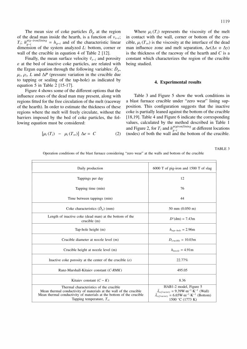
Figure 4 shows some of the different options that theinfluence zones of the dead man may present, along withregions fitted for the free circulation of the melt (racewayof the hearth). In order to estimate the thickness of theseregions where the melt will freely circulate, without thebarriers imposed by the bed of coke particles, the fol-lowing equation must be considered:
[µi (Ti) − µi (T∞)
]∆e = C (2)
Where µi (Ti) represents the viscosity of the meltin contact with the wall, corner or bottom of the cru-cible, µi (T∞) is the viscosity at the interface of the deadman influence zone and melt separation, ∆e(∆x o ∆y)is the thickness of the raceway of the hearth and C is aconstant which characterizes the region of the cruciblebeing studied.
4. Experimental results
Table 3 and Figure 5 show the work conditions ina blast furnace crucible under “zero wear” lining sup-position. This configuration suggests that the inactivecoke is partially leaned against the bottom of the crucible[18,19]. Table 4 and Figure 6 indicate the correspondingvalues, calculated by the method described in Table 1and Figure 2, for Ti and hpigiron/lining
g−i at different locations(nodes) of both the wall and the bottom of the crucible.
TABLE 3Operation conditions of the blast furnace considering “zero wear” at the walls and bottom of the crucible
Daily production 6000 T of pig-iron and 1500 T of slag
Tappings per day 12
Tapping time (min) 76
Time between tappings (min) 44
Coke characteristics (Dp) (mm) 50 mm (0.050 m)
Length of inactive coke (dead man) at the bottom of thecrucible (m) D∗(dm) = 7.43m
Tap-hole height (m) htap−hole = 2.96m
Crucible diameter at nozzle level (m) Dcrucible = 10.03m
Crucible height at nozzle level (m) hnozzle = 4.91m
Inactive coke porosity at the center of the crucible (ε) 22.77%
Ranz-Marshall-Kitaiev constant (C-RMK) 495.05
Kitaiev constant (C − K) 8.36
Thermal characteristics of the crucibleMean thermal conductivity of materials at the wall of the crucible
Mean thermal conductivity of materials at the bottom of the crucibleTapping temperature, T∞
HAB1-2 model, Figure 5λre f ractory = 9.39W·m−1·K−1 (Wall)λre f ractory = 6.65W·m−1·K−1 (Bottom)
1500 ◦C (1773 K)

1120
Fig. 5. HAB1-2 crucible and materials used in its lining
TABLE 4Temperatures (Ti) and global heat transport coefficients at some positions (nodes) at the
bottom and wall of the crucible (hpig−iron/liningg−i )
Node Position (x; y) hpig−iron/liningg−i (W·m−2·K−1) Temperature, Ti(oC)
0 (bottom) (0.00 ; 0.00) 40,0 1434
1 (bottom) (- 0.67 ; 0.00) 40,5 1434
2 (bottom) (-1.34 ; 0.00) 41,0 1433
3 (bottom) (-2.01 ; 0.00) 42,0 1432
4 (bottom) (-2.67 ; 0.00) 42,5 1432
5 (bottom) (-3.01 ; 0.00) 43,5 1431
6 (bottom) (-3.34 ; 0.00) 45,0 1431
7 (bottom) (- 3,68 ; 0.00) 75,0 1453
8 (bottom) (-4.35 ; 0.00) 105,0 1467
9 (corner) (-5.01; 0.00) 53.0 1383
10 (wall) (-5.01; 0.85) 94.8 1439
11 (wall) (-5.01;1.69) 94.8 1440
12 (wall) (-5.01; 2.54) 93.5 1445
9* (Taphole) (-5.01; 2.96) 91.0 1460

1121
Using the calculated nodal properties (Ti andhpigiron/lining
g−i ) along the pig iron – refractory interface,certain characteristics of the particles at the bed of in-active coke may also be calculated: porosity (ε), cokeparticles mean size (Dp), global heat transport coeffi-cients between the coke and the melt (hcoke/melt
g−i ) and/orsuperficial speed of the melt in contact with the coke(vs−i or vs−i). Furthermore, the position of nodes 4*, 5*
and 6* at the interface of the static bed of coke and themelt may also be defined, along with the position of node13, which is an indication of the influence of the cokein the zone II of the blast furnace crucible (Figure 6).
Table 5 presents the characteristics of the static bedof coke particles at zone I (below the tap-hole) and Table6 corresponds to zone II (above the tap-hole), shown atFigure 6.
TABLE 5Mean coke particle size (Dp), superficial speed (vs−i o vs−i) and porosity of the particle bed (ε) at Zone I of the crucible
Node Dp(m) vs−i(m·s−1) ε(%) Node Position(x;y) vs−i(m·s−1)0 0.0500 1.175·10−2 22.77 0∗ (0.00; 2.96) 3.082·10−2
1 0.0496 1.184·10−2 22.88 1∗ (-0.67; 2.96) 3.105·10−2
2 0.0492 1.192·10−2 23.04 2∗ (-1.34; 2.96) 3.128·10−2
3 0.0485 1.211·10−2 23.35 3∗ (-2.01; 2.96) 3.175·10−2
4 0.0481 1.218·10−2 23.51 4∗ (-2.67; 2.96) 3.198·10−2
5 0.0272 1.236·10−2 31.76 5∗ (-3.01; 1.95) 4.924·10−2
6 0.0088 1.263·10−2 54.17 6∗ (-3.34; 0.85) 11.541·10−2
7 0.0003 1.791·10−2 78.25 – – 16.365·10−2
8 0.0001 11.766·10−2 98.82 – – 107.511·10−2
TABLE 6Mean superficial speed (vs−i), porosity (ε) and global heat transfer coefficients (hcoke/ f luid
g−i ) of nodes at the inactive coke influence zone forZone II of the crucible
Node Position (x;y) hcoke/ f luidg−i (W·m−2·K−1) ε(%) vs−i(m·s−1)
0** (0.00; 3.85) 93.6 22.77 5.691·10−2
1** (-0.67; 3.85) 94.8 22.88 5.715·10−2
2** (-1.34; 3.85) 96.0 23.04 5.757·10−2
3** (-2.01; 3.85) 98.4 23.35 5.844·10−2
4** (-2.67; 3.85) 99.6 23.51 5.886·10−2
5** (-3.01; 3.85) 100.4 23.57 5.904·10−2
6** (-3.34; 3.85) 101.2 23.67 5.930·10−2
7** (-3.68; 3.85) 102.0 23.77 5.956·10−2
8** (-4.35; 3.85) 103.6 23.96 6.008·10−2
1122
Fig. 6. Inactive coke influence zone and positions where the flow/porosity of the crucible may be measured
5. Conclusions
The nodal wear model represents an efficientcomplement to work with and interpret experimentalisotherms at the lining of any given 2D section of ablast furnace crucible, and the possibility to obtain thefollowing:1. The resulting differential wear of the refractories that
constitute the working lining of the furnace crucibleat any specific zone: walls, corners or bottom.
2. In the same way noticeable wear at corners or centralpart of the crucible may be detected in a 2D section.Formation of protective scabs at the walls or bottommay also be detected.
3. The erosion of the lining reflects in the values ofTi and ofhpig−iron/lining
g−i , independently from the factthat the wear mechanism acting is of the chemical ormechanical type.
4. Starting from the Ti and hpig−iron/liningg−i values, in a
determined 2D section of the crucible, coke proper-ties may be estimated, along with the major or minorinfluence of the dead man region with respect to thezones where the melt freely circulates (raceway ofhearth).
5. Considering the results in different 2D sections ofthe crucible for an specific moment in the operationlife of the furnace, a 3D representation may be pos-
sible, including both of the refractory lining profilesas well as those corresponding to the dead man in-fluence zone.
Acknowledgements
The authors wish to thank the Ministry of Education and Sci-ence (MEC): MAT2003-00502, the Ministry of International Affairsand Cooperation (MAEC): MAEC-AECI-B/1629/04; B/2884/05;B/5814/06, B/7648/07 and the CSIC-Madrid (Spain) for making thescientific and technological cooperation between CENIM/CSIC andOviedo University possible through the “Associated Unit”.
This work was based on fruitful cooperation between theCSIC-Madrid (Spain) and the AGH University of Science & Tech-nology.
REFERENCES
[1] Y. O m o r i, Blast furnace phenomena and modelling,Ed. Elsevier, England, 345-352, 395-405 (1987).
[2] F. H a b a s h i, Handbook of Extractive Metallurgy.Metal Industry: Ferrous Metals I, Ed. Wiley-VCH, Ger-many, 57-104 (1997).
[3] J.P. B e n n e t t, J.D. S m i t h, American Ceramic So-ciety, Ceramic Transactions 125, 135-154 (2001).
[4] L.F. V e r d e j a, J.P. S a n c h o, A. B a l l e s t e r,Materiales Refractarios y Ceramicos, Sıntesis, 19-22;156-176, Madrid (2008).

1123
[5] M.A. R o m e r o, J. J i m e n e z, J. M o c h ó n, J.L.M e n e n d e z, A. F o r m o s o, F. B u e n o, Rev. Met-al. Madrid 36, 1, 40-46 (2000).
[6] R. P a r r a, L.F. V e r d e j a, M.F. B a r b e s, C.G o n i, V. B a z a n, JOM 57, 10, 29-36 (2005).
[7] C. G o n i, M.F. B a r b e s, V. B a z a n, E. B r a n -d a l e z e, R. P a r r a, L.F. V e r d e j a, J. Ceram. Soc.Jpn 114, 8, 665-668 (2006).
[8] H.B. L u n g e n, H.P. R u t h e r, G. C l i x b y, G.C a s s e l l a, Investigations on blast furnace wear phe-nomena especially in the heart, European Commission.Technical Steel Research. EUR 19347 EN, 193 (2000).
[9] K. M u l h e i m s, W.D.N. P r i t c h a r d, J.M.S t e i l e r, M. S c h u l t e, Wear blast furnace heart,European Commission. Technical Steel Research. EUR20109 EN, 272 (2002).
[10] J.P. S a n c h o, L.F. V e r d e j a, A. B a l l e s t e r,Metalurgia Extractiva: Procesos de obtención, Sıntesis,Madrid 2000, 55-74 (2000).
[11] S.A. Z a ı m i, M.J. V e n t u r n i, D. S e r t, Rev.Metall-Paris, Journees Siderurgiques ATS-2002, 99, 11,18-19 (2002).
[12] O. H a v e l a n g e, G. D a n l o y, J.M. V e n t u r i -n i, H. P i e r r e t, H.P. R u t h e r, O. M i e l e n z, H.K o c h n e r, J.A. A l e x a n d e r, J.R. P o s t a n d, G.
C l i x b y, Determination of coke bed voidage in theblast furnace hearth, European Commission. TechnicalSteel Research. EUR 20942 EN, 194 (2004).
[13] G. D a n l o y, M. F a l z e t t i, A. F o r m o s o, E.H e r f u r t h, J. V e g a, Modelling of gas and char flowsat high PCI through experimental and theoretical studiesof the raceway and the dead man. European Commis-sion. Technical Steel Research. EUR 20094 EN/DE, 224(2002).
[14] C.B. A l c o c k, Principles of pyrometallurgy, AcademicPress, London, 98-99 (1976).
[15] A. B a l l e s t e r, L.F. V e r d e j a, J.P. S a n c h o,Metalurgia Extractiva: Fundamentos, Sıntesis, Madrid,235-238 (2000).
[16] D.R. P o i r i e r, G.H. G e i g e r, Transport phenom-ena in materials processing, TMS, Pennsylvania, 93-98(1994).
[17] J. J i m e n e z, J. M o c h o n, J. S a i n z d e A y a l a,ISIJ Int. 44, 3, 518-526 (2004).
[18] Ma. F. B a r b e s, E. M a r i n a s, E. B r a n d a l e z e,R. P a r r a, L.F. V e r d e j a, G.A. C a s t i l l o, R.C o l a s, ISIJ Int. 48, 2, 134-140 (2008).
[19] R. M a r t ı n D u a r t e, M.A. B a r b e s, E. M a r i -n a s, N. A y a l a, J. M o c h ó n, L.F. V e r d e j a, F.G a r c ı a, Rev. Metal. Madrid 45, 4, 295-304 (2009).
Received: 10 April 2010.