angular distribution of thick-target bremsstrahlung which
TRANSCRIPT

N A S A
m 40 0
0
z c 4 VI 4 z
P
TECHNICAL NOTE NASA 7
TN D-4063
ANGULAR DISTRIBUTION OF
WHICH INCLUDES MULTIPLE ELECTRON SCATTERINGS
THICK-TARGET BREMSSTRAHLUNG
by We Wuyne Scott
Ldngley Reseurch Center Ldngley Station, Humpton, Viz.
NATIONAL AERONAUTICS AND SPACE ADMINISTRATION WASHINGTON, D. C. AUGUST 1967
https://ntrs.nasa.gov/search.jsp?R=19670022792 2019-01-05T18:00:17+00:00Z

--- J ' P I i, 1 . . J
TECH LIBRARY KAFB. NM
0330978
ANGULAR DISTRIBUTION O F THICK-TARGET BREMSSTRAHLUNG
WHICH INCLUDES M U L T I P L E E L E C T R O N SCATTERINGS
By W. Wayne Scot t
Lang ley R e s e a r c h C e n t e r
Lang ley Station, Hampton, Va.
NATIONAL AERONAUTICS AND SPACE ADMINISTRATION
For sale by the Clearinghouse for Federal Scientific and Technica l Information Springfield, Virginia 22151 - CFSTI price $3.00
ANGULAR DISTRIBUTION OF THICK-TARGET BREMSSTRAHLUNG
WHICH INCLUDES MULTIPLE ELECTRON SCATTERINGS *
By W. Wayne Scott Langley Research Center
SUMMARY
A theoretical analysis which includes multiple electron scattering as described by a random-walk procedure is presented for predicting the spectrum of bremsstrahlung produced at angles relative to a monoenergetic f lux of electrons Df normal incidence on thick targets. The assumption is made that the spectral and angular distribution of radi- ation leaving a thick target can be considered to be the sum of the contributions from a ser ies of thin strips, one behind the other, bombarded by electrons of continuously decreasing energy. The following processes are considered in the analysis: tion of electrons in thin targets as predicted by the Bethe-Heitler theory; (2) electron penetration into the target which includes (a) multiple electron scattering as predicted by Goudsmit-Saunderson theory, (b) electron backscatter out of the target, (c) electron energy loss in the target, and (d) electron-electron bremsstrahlung; and (3) the absorp- tion and buildup of photons in the target. Comparisons are made between the calculated resul ts and experimental data for aluminum and iron thick targets. On the whole the agreement is reasonably good.
(1) radia-
INTRODUCTION
Electrons that exist in the radiation belt (for example, ref. 1) surrounding the earth present a radiation hazard to man and equipment in space explorations. manned space vehicles from electrons is primarily in the form of penetrating secondary radiation produced by the energy degradation of electrons in the space-vehicle wall. The radiation, designated as bremsstrahlung, results from interactions of the incoming elec - t rons with the charged particles (nuclei o r electrons) of which the vehicle wall is composed.
This hazard to
- ~-
*Some of the information presented herein was included in a thesis entitled "A Formula for Predicting the Angular Distribution of Thick Target Bremsstrahlung" sub- mitted in partial fulfillment of the requirements for the degree of Master of Arts, The College of William and Mary in Virginia, Williamsburg, Virginia, 1965.

A vehicle wall could be treated as a thin target if, while traversing the wall, the incident electron has only one radiative collision, suffers no significant elastic deflection, and loses no appreciable energy by ionization. However, in practice, these conditions seldom exist. Generally a space-vehicle wall will be representative of a thick target; that is, the wall will be of such a thickness that the majority of the incident electrons will lose sufficient energy to be stopped. For this case, the description of the brems- strahlung field behind the target is a difficult problem, complicated by multiple electron scattering, electron energy losses, photon absorption, and shower production.
Previous estimates of the bremsstrahlung spectra from thick targets for electrons with energies of the order of the rest-mass energy (0.511 MeV) have depended upon the theory developed by Kramers. (See ref. 2.) However, the validity of Kramers’ theory is limited in that the theory estimates the photon energy distribution integrated over all directions of the emitted photons and the theory is nonrelativistic. Estimates have also been made by Wilson (ref. 3), the author of the present paper (ref. 4), and others but these results a r e also in the form of an average over the direction of photon emission and no attempt is made to account for multiple electron scattering within the target.
The analysis presented herein is intended t o provide a basic formula for approxi- mating, with a reasonable degree of accuracy, the thick-target bremsstrahlung spectrum. This approximating capability is important for shielding studies since experimental data a r e scarce and there is a need for theoretical data over a wide electron energy and material range.
The procedure for computing the bremsstrahlung spectra is programed in the FORTRAN (FORmula TFtANslation) IV language for the IBM 7094 electronic data pro- cessing system at the Langley Research Center.
SYMBOLS
A atomic weight of target material
A19 “1’ A27 a2 photon buildup coefficients
B photon buildup factor
C speed of light, centimeters per second
2 E total electron energy, in units of mOc
2

E i
E'
Eq
EO
e
h
- I
mO
mOC 2
N
NA
N a
n
p€
P
P O
total energy of electron emergent from thin target i (i = 1, 2, . . ., n), in units of moc 2
2 total electron energy after scattering, in units of
residual energy of scattering center after collision, in units of
initial total electron energy, in units of
electron charge, electrostatic units
Planck constant, 6.6254 x erg-seconds
mean ionization potential, in units of
indexing integers
vector energy of emitted photon, in units of
electron r e s t mass, grams
electron rest-mass energy, 0.511 MeV
3 atomic density, atoms per centimeter
Avogadro's number, atoms per gram-mole
moc
2 mOc
2 moc
2 moc
2 moc
number of atoms per centimeter per unit area, atoms per centimeter 3
number of thick-target subdivisions
probability of electron being scattered at an angle E
Leg e ndr e polynomial
electron momentum vector, in units of
initial electron momentum vector, in units of
moc
moc
3

P' momentum vector of electron after scattering, in units of moc
electron spatial displacement vector, g rams per centimeter2 r
classical electron radius, 2.81784 X centimeter rO
T 2 electron kinetic energy, in units of mOc
2 initial electron kinetic energy, in units of moc TO
path length traversed by electron t
line-of-sight distance in target material between source point of photon and point at which the photon exits back surface of thick target, grams per centimeter2
- t 2 mean target thickness, grams per centimeter
electron velocity after collision, centimeters per second V
electron velocity before collision, centimeters per second vO
W ratio of backscattered electrons to primary electrons
coordinate axes of target
atomic charge number Z
P number of increments in the angle E
number of increments in the angle I,L 6
polar angle of electron, degrees E
polar angle of electron in thin target i, degrees 'i
photon emission angle of k with respect to po, degrees
5 fir st -approximation correction factor
4

IJ-m
P
do
2 photon mass absorption coefficient, g rams per centimeter
3 density of target material, grams per centimeter
differential bremsstrahlung cross section, centimeter2 per atom-electron
polar angle referred to k, degrees
polar angle of detector with respect to incident electron direction, degrees
polar angle of electron in thin target i, degrees
solid angle, steradians
THEORY O F THICK-TARGET ANALYSIS
For a monoenergetic, monodirectional beam of electrons incident on a thick target,
This analysis takes into account various aspects of electron penetration a random-walk computer program for the analysis of thick-target bremsstrahlung has been generated. and diffusion: angular deflection, energy losses, spatial propagation, and the radiative process of scattering. The large number of interactions (running into the tens of thou- sands) which an electron may undergo in a thick target makes it necessary to resor t to a sophisticated scheme in which rriany successive collisions a re grouped into a single step of an artificial random walk. The scattering probabilities for the random walk are then obtained from pertinent analytical multiple electron scattering theories (e.g., ref. 5) gov- erning angular deflections and energy losses.
The random-walk scheme must provide, for each step of the random walk, a rule a change of for selecting an energy-loss increment Ei - Ei+l, a step length
electron direction from ( ea, t,by) to ba+l,t,by+l), and a spatial displacement Ti - ri+l.
A great variety of schemes are possible, which differ with regard to the input parameters and the necessary amount of computing time. The rules used for the random-walk sam- pling presented herein have been described in some detail by Berger in reference 5.
ri - -
For this analysis a continuous slowing-down approximation is used to select a con- stant electron energy loss AE = Ei - Ei+l; that is, the thick target is subdivided into a number of thin s t r ips in each of which an electron energy loss AE occurs. For example, one may consider a target those thickness corresponds to the range of a
5
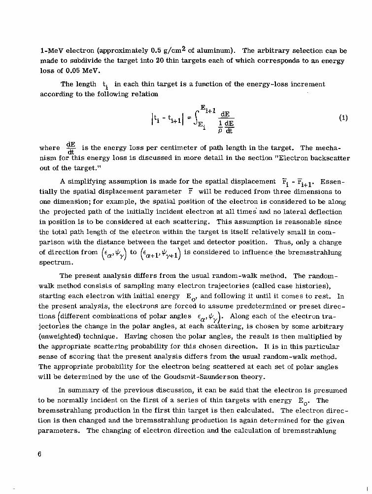
1-MeV electron (approximately 0.5 g/cm2 of aluminum). The arbitrary selection can be made t o subdivide the target into 20 thin targets each of which corresponds to an energy loss of 0.05 MeV.
The length ti in each thin target is a function of the energy-loss increment according to the following relation
where dE - is the energy loss per centimeter of path length in the target. The mecha- dt
nism for this energy loss is discussed in more detail in the section "Electron backscatter out of the target."
A simplifying assumption is made for the spatial displacement Fi - Fi+l. Essen- tially the spatial displacement parameter r will be reduced from three dimensions to one dimension; for example, the spatial position of the electron is considered to be along the projected path of the initially incident electron at all t imes and no lateral deflection in position is to be considered at each scattering. This assumption is reasonable since the total path length of the electron within the target is itself relatively small in com- parison with the distance between the target and detector position. Thus, only a change of direction from €@,IC;) to (Ea+l, + y+l ) is considered to influence the bremsstrahlung spectrum. (
The present analysis differs from the usual random-walk method. The random- walk method consists of sampling many electron trajectories (called case histories), starting each electron with initial energy Eo, and following it until it comes to rest . In the present analysis, the electrons a re forced to assume predetermined or preset direc- tions different combinations of polar angles E ,+ ) jectories the change in the polar angles, at each scattering, is chosen by some arbitrary (unweighted) technique. Having chosen the polar angles, the result is then multiplied by the appropriate scattering probability for this chosen direction. It is in this particular sense of scoring that the present analysis differs from the usual random-walk method. The appropriate probability for the electron being scattered at each set of polar angles will be determined by the use of the Goudsmit-Saunderson theory.
Along each of the electron tra- ( Y '
In summary of the previous discussion, it can be said that the electron is presumed to be normally incident on the first of a ser ies of thin targets with energy bremsstrahlung production in the first thin target is then calculated. The electron direc- tion is then changed and the bremsstrahlung production is again determined for the given parameters. The changing of electron direction and the calculation of bremsstrahlung
Eo. The
6

production is continued until all the predetermined angles have been assumed. The electron is then considered to be entering into the second thin strip at a normal angle of incidence with an energy of Eo - AE. This procedure of changing the angles and calcu- lating the bremsstrahlung production is again repeated. This sequence of events (random- walk steps) is continued until the electron has been brought to rest. The thick-target spectrum is then considered to be the sum of the radiation contributions from each thin strip.
In the next section the complex processes of electron penetration and radiation a re discussed in more detail, after which a formula for approximating the bremsstrahlung spectrum is derived.
ELECTRON RADIATIVE AND SCATTERING MECHANISMS
Radiation in a Thin Target
In passing through the field of a nucleus (or atom) an electron with energy E is deflected. As a result of this deflection there exists a certain probability that a light quantum (photon) of energy k is emitted with the electron making a transition to another state with residual energy E', where
E = E' + k + Eq (2)
Photon k
Scattering center recoil E , p
the initial momentum of the incident elec-
This interaction is shown in figure 1. In the radiative collision, shown in figure 1,
tron becomes shared among three bodies: the residual electron, the scattering center, and the emitted photon. Therefore, the Residual electron E',p'
photon can have any energy up to the energy of the incident electron.
,ncidentelectron E,p 3 Figure I.- Radiative collision i n a t h in target.
The major part of the quantum-mechanical theory for predicting thin-target brems- strahlung differential c ros s sections has been obtained by Bethe, Heitler (ref. 6), and others using the Born approximation. This approximation is valid provided
and 2 .2nZe.. 1
hv
I
(4)
7

where vo and v represent the electron velocity before and after the collision, respec- tively. scattered electrons move with relativistic speeds. The Bethe -Heitler formula can be expressed as a differential with respect to two parameters, photon energy k and the solid angle 51, as shown by the following equation. (See eq. (2BN) of ref. 7.)
For light elements equations (3) and (4) are always satisfied if the primary and
2 2 do=--- z ro
sin200(2E: + 1) 2(5E: + 2EE0 + 3) 2(p: - k") +- 4E
877 137 po k P02A2 PO2A? Q2A02 P,2AO
PO2A2 Po2A02 P2AO2
sin200(3k - p 2 E ) 4E,2(E,2 + E2) 2 - 2(7E: - 3EE0 + E") - + +
where
EEo - 1 + PPo
2 Q = po2 + k2 - 2p0k cos 8,
A o = E - p COS Bo 0 0
and
Equation (5) represents the probability that a photon whose energy l ies between the limits k and k + dk shall be emitted within a differential solid angle d a y oriented at
8
I

. . . - .. . .
some angle electron of total energy Eo collides with a thin target of atomic number Z. This col- lision geometry is shown in figure 2 for an electron approaching the origin along a positive Z-direction with momentum and colliding with a thin target which is considered to lie in the X-Y plane, perpendicular to the electron direction.
8, with respect to the direction of motion of the incident electron when an
po
Various corrections must be made to the cross-section formula given by equa- tion (5). These corrections may be classified according to three types:
(1) Coulomb corrections (2) Screening corrections (3) Failure of the Born approximation at the high-frequency limit
Corrections (1) and (2) are significant in particular energy regions. This restriction on the energy region is unfortunate in that in the region of interest, approximately 0.1 to 2.0 MeV (intermediate energies), Coulomb corrections are not available in analytical form and empirical corrections cannot be determined in enough detail from the available data to cover the entire energy range. The screening corrections a re not necessary in the intermediate energy region.
The problem of a high-frequency correction, or equivalently the problem of cor- recting the c ross section for its larger e r r o r with increasing photon energy, is discussed in the section "The buildup and absorption of photons in the target."
Thin target
.-
2 lo?
10' Photon k
X /
Incident electron Figure 2.- Collision geometry of radiative process.
\ \
\
\
0 .2 .4 .6 .8 1.0
Photon energy, k, MeV Figure 3.- Dependence of thin-target bremsstrahlung
intensity spectrum on k and 8,. To = 1.0 MeV.
9

In reference 4, the thin-target bremsstrahlung c ross section w a s computed by using the Bethe-Heitler formula for a wide range of electron energies and for 8, equal to Oo, 30°, 60°, and 90'. One such spectrum from reference 4 is presented in figure 3 for a 1-MeV electron. For convenience the curve has been made independent of the atomic number Z, and the c ros s section is for a unit monoenergetic electron flux. It should be noted that the radiation intensity is peaked in the forward direction.
Electron Penetration Into a Thick Target
Multiple electron ~~ scattering. ___ - The phenomenon of an electron undergoing a large number of scatterings within a thick absorber is commonly referred to as multiple elec- tron scattering. Each scattering results in an energy loss and a change of direction for the electron. As a consequence of the multiple electron scattering the angular distribu- tion of the thick-target bremsstrahlung is altered. This alteration is recognized since the thin-target bremsstrahlung cross section (eq. (5)) is a function of the angle between the electron direction and the photon direction (detector direction) as shown in figure 4.
-
0 yL7 _ _ - _ _ - _ 1 2 - - Scattering center e
0,l Figure 4.- Multiple electron scattering.
Therefore, if multiple electron scattering is to be included in the theoretical analysis, the array within each thin s t r ip as illustrated in diagram A must be predicted.
The probability PE can be predicted by one of the many multiple scattering '
theories, some of which are based on the assumption that the scattering process is ade- quately described by ordinary diffusion. Goudsmit and Saunderson (ref. 8) have derived an expression of multiple Rutherford scattering by using a Legendre ser ies expansion and assuming a continuous slowing dawn of the electron in the absorber. Their results a r e considered valid for all scattering angles and can be used with an appropriate single- scattering c ross section, for example, a Mott c ross section.
The evaluation of the Goudsmit-Saunderson theory is discussed in detail by Berger (ref. 5) who makes use of various procedures developed by Spencer (ref. 9) that facilitate the numerical evaluation of the angular multiple- scattering distribution function. The
10

i = l
E1
E l
*l
a0,1
P€ ,1
(&)l
i = 2
E2
€ 2
*2
60,2
p, ,2
i = n - 1
En-1
en-1
qn-1
60,n-l
'e ,n-1
\ n-1
i = n
En
En
*n
'o,n
P E ,n
(&)n
Diagram A
expression developed by Berger for the intensity of scattering per unit solid angle in the direction E is given by
P, = (I + i) exp[ lot GI(t?)dt]PI(cos E )
I =o
where
GI@') = 2 r N J' a(e,ti) 1 - p2(cos e) sin e dB 0 " c 1
and
N number of atoms per unit volume
t path length traversed by electron
4 8,t') single -scattering c r o s s section, whose dependence on the electron energy is expressed in the continuous slowing-down approximation, through the path length t
This expression (eq.(6)) is most applicable to a random-walk procedure where the target is subdivided into equal path lengths.
11
I

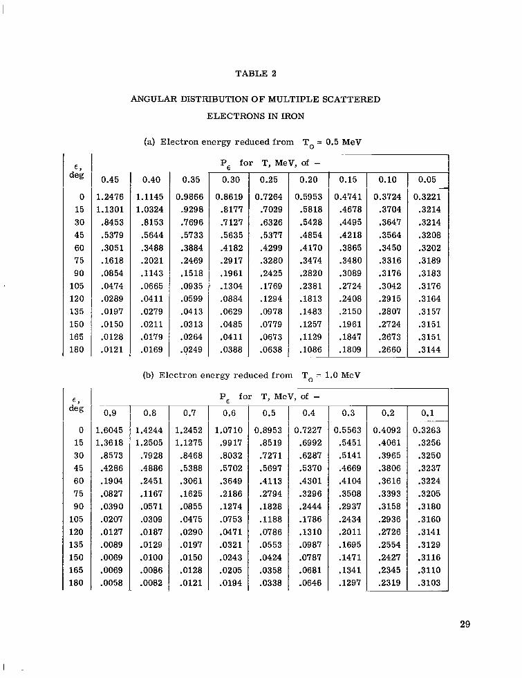
Results of an evaluation of equation (6) are presented in tables 1 and 2 for aluminum and iron and electron energies of 0.5 and 1.0 MeV. A typical plot of the multiple scattering is shown in figure 5 where the relative scattering probability is plotted as a function of the electron kinetic energy and angle of scattering.
Electron backscatter ~ - out of the - - target.- When a stream of electrons is directed against a solid target most of the electrons penetrate the target; however, some a re emitted from the incident surface. A few of these returning electrons may be the products of collisions and are classed as secondary electrons. However, they are generally slow, most of them having an energy less than 50 eV. Most of the returning electrons, however, a r e members of the original beam, which have penetrated to a greater or lesser extent into the target, suffered elastic or inelastic collisions or both, and return to escape the front surface; thus, a reduction in the forward-going incident beam intensity takes place.
Several authors have made measurements to determine electron backscattering for elec- trons within the energy range of interest. One such plot using data from reference 10 is shown in figure 6 where the ratio of backscattered to primary electrons is plotted as a function of the target atomic number and the electron kinetic energy.
Electron energy loss - - in the target.- The energy loss of electrons in a medium essentially occurs by two different mechanisms. The pre- dominant mechanism of the energy degradation at low energies is due to the inelastic collisions
lol l i \
10- 0 30 60 90 120 150 180
Polar angle, E, deg Figure 5.- Angular distribution of multiple scattered electrons
in aluminum in which electron energy i s reduced from To = 1.0 MeV.
T, MeV
v) c 0 L
c V m P)
x L
-
s .- L
0 - UI c
n
2 c V m P)
V P) L m
m
Y u
-
5 :: 2 c 0 0
m E
.- c
'. 0
0 20 40 60 80 100
Target atomic number, 2 Figure 6.- Ratio of backscattered electrons to
primary electrons as a function of target atomic number.
12
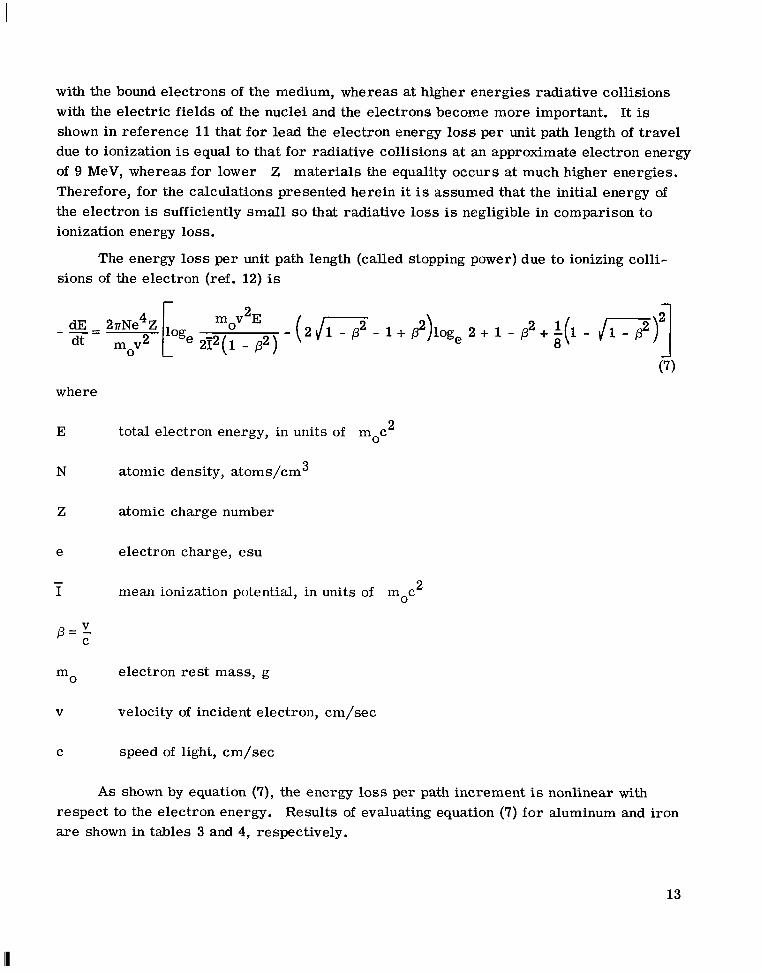
with the bound electrons of the medium, whereas at higher energies radiative collisions with the electric fields of the nuclei and the electrons become more important. It is shown in reference 11 that for lead the electron energy loss per unit path length of travel due to ionization is equal to that for radiative collisions at an approximate electron energy of 9 MeV, whereas for lower Z materials the equality occurs at much higher energies. Therefore, for the calculations presented herein it is assumed that the initial energy of the electron is sufficiently small so that radiative loss is negligible in comparison to ionization energy loss.
The energy loss per unit path length (called stopping power) due to ionizing colli- sions of the electron (ref. 12) is
2 dE - 2rNe4Z Loge mov E - ( 2 J- - 1 + P2)loge 2 + 1 - p2 + q 1 8 - ii-p.)"]
2 2 9 ( 1 - p) - -- dt m v
0 (7)
where
E total electron energy, in units of moc 2
N atomic density, atoms/cm 3
Z atomic charge number
e electron charge, esu
2 - I mean ionization potential, in units of moc
electron res t mass, g mO
V velocity of incident electron, cm/sec
C speed of light, cm/sec
As shown by equation (7), the energy loss per path increment is nonlinear with respect to the electron energy. Results of evaluating equation (7) for aluminum and iron are shown in tables 3 and 4, respectively.
13

Correction for electron-electron - bremsstrahlung. - When considering the passage of an electron through a medium, one must take into account the fact that the electron may also collide with the electrons of the atoms of which the medium is composed and produce bremsstrahlung. Calculations have been made to determine the exact electron-electron bremsstrahlung cross sections. (See ref. 6.) These calculations show that the final cross-section formula for electron-electron bremsstrahlung differs little (except for a factor of Z2) from the original electron-nucleus c ros s section for bremsstrahlung pro- duction. This conclusion is reasonable since large momentum transfers to a single elec- tron are, though possible, rare and contribute little to the total bremsstrahlung cross section. The electron-electron bremsstrahlung contribution to the total bremsstrahlung c r o s s section can thus be taken into account with a reasonable degree of accuracy by replacing the Z2 factor in the Bethe-Heitler formula (eq. (5)) by Z(Z + 1).
The buildup and absorption of photons in _ _ _ - _ the target.- When gamma rays traverse -_ matter, they interact through separate "elementary" processes which have the effect of attenuating the photons either by outright absorption or by degradation in energy and deflection. These predominant elementary processes a re the photoelectric effect, Compton scattering, and pair production.
In the photoelectric effect a photon disappears and an atomic electron leaves its This effect is predominant for low-energy atom, having absorbed the photon energy.
gamma rays, especially in high Z materials.
In Compton scattering a photon is scattered inelastically and an atomic electron recoils out of an atom. This effect is predominant for 1- to 5-MeV gamma rays.
For pair production a gamma ray of more than 1 MeV disappears, and its energy This effect is predominant for high gamma ray t ransfers to an electron-positfon pair.
energies, especially in high Z materials.
The interaction of gamma r a y s with matter results in an exponential attenuation of the gamma rays in the absorber. The number of photons traveling in the original inci- dent direction after a distance of penetration t into the absorber is given by a function
of the form e where pm represents the mass attenuation coefficient (probability of a process per g/cm2).
-Pmt
The interaction processes experienced by photons give rise to a variety of second- ary radiations, such as Compton scattered photons, electrons ejected in the photoelectric process, and pair-production electrons. The decay of the photoelectric and pair- production electrons results in secondary photons which influence the whole process of photon production. This effect of secondary photon generation in the absorber can be taken into account by the use of a buildup factor which is defined to be the ratio of the
14

I . .... . . -
total number of gamma rays at any one point .to the number of primary gamma rays. An expression (found in ref. 13) for the buildup factors is given by
B(pm,t) = A1 exp ( 1 m ) -a p t + A2 exp(-a 2 p mt) (8)
where .
p m mass attenuation coefficient at source energy k
ApapA2,a2 coefficients adjusted to f i t experimentally determined data or theoretical data determined by Monte Carlo calculations
Tables 5 and 6 show the attenuation and buildup coefficients pm, A1, al, A2, and a2 for aluminum and iron, respectively.
DERIVATION OF THE THICK-TARGET EQUATION
It is now possible to approximate the angular distribution of bremsstrahlung behind a thick target by the combination of the complex processes discussed in the preceding sections.
Consider an electron of normal incidence on a thick target where the target has been subdivided into thin s t r ips as shown in diagram B.
E O
O--- Incident electron
I
Diagram B
Within each thin target the electron will travel in some direction defined by the two polar angles E and e. A schematic representation of a radiative scattering in any slab i is shown in figure 7.
15
I

IIIIIIII I
- Y
d Electron
Figure 7.- General radiative scattering in th in target.
In this figure, E
the incident electron direction. Recall that the angle 8, is the angle between the elec- tron velocity vector and the emitted photon. Note that only photons traveling at an angle +d with respect to the incident electron direction will reach the detector.
is the angle between the electron velocity vector in the ith slab and
For a thick target which 2
consists of many thin targets there will occur a scattering, typical of the scattering shown in figure 7, in each thin tar- get. Figure 8 is representa- tive of the present analysis of the multiple electron scat- tering that occurs in a thick target. Again as in figure 7, E and Q a r e the polar angles with E representing
dent electron direction and the electron velocity vector in the ith slab. Recall that the assumption is made that the lateral displacement of the electron within the target is very small compared with the distance between the target and detector and has negligible effect on the thick-target
I
Y
Figure 8.- Multiple electron scattering i n thick target. the angle between the inci- X
16

spectrum. Thus the multiple scattering is considered to influence the spectrum only through changes in the electron direction with respect to the initially incident electron direction.
The path shown in figure 8 is certainly not unique. In other words, the path of the electron in the target is random; therefore, it is necessary to consider all directions of electron scattering in each slab relative to the initial electron direction. Within each slab all possible combinations of E and @ (fig. 7) are to be considered along with the representative probability of the electron having each particular combination of angles.
Now consider for each thin target a cylindrical differential element of volume dV having a normal unit area and length A t (slab thickness) relative to the initial electron direction. The total probability for the emission of a photon of energy k in the direc- tion Bo in each thin s t r ip for a specified ea, qY, and @d is
where Na is the number of atoms/cm3. The photon energy release is dependent upon the angles E , @, and c#~ , where these angles a r e related by the eba t ion
cos 8 = cos cos +d + sin ea sin @d cos @ (10) 0 Y
Expression (9) is an unweighted function with respect to the electron direction. The probability of the photon energy release must be correlated with the probability (weighted function) of the electron having the specific values of E@ and tering probability is expressed in equation (6) as a function of the particular thin target, electron energy, and angle E . Hence,
qY. This scat-
Thus for one electron direction of ea and qY the probability of the generation of a photon of energy k that will reach the detector at an angle Gd is the product of the two probabilities
17

For all angles of electron direction within each slab, that is, for E varying from 0 to r and t,b varying from 0 to 277, the total radiative probabilities in slab i are
where
a: p, y, 6 integers
277 A + = - 6
It is now necessary to sum these probabilities over the electron energy (or the corre-
sponding thickness of the target necessary to bring the electron to rest). In theory it is possible to determine the differential path length of an electron within an absorber with the aid of equation (7), which is the relation expressing electron energy loss per unit path length. The differential path length is expressed as
dE dt = -
or
AE dE dt
At = - -
where
EO AE - n
Substituting equation (15) into equation (13) and summing over i slabs in te rms of the electron energy give
18

Only electrons with energies greater than k can create photons of energy k; thus, a lower limit is placed on the energy summation. Rewriting and regrouping equation (16) and expressing the electron energy in t e rms of the total electron energy give
The additional processes of photon absorption and buildup, electron-electron brems- strahlung, and backscattering as previously discussed can now be included in equation (17) as follows:
EO = N,Z(Z + 1)(1 - W) 1
(&)thick target k+moc2 PE sin E de dlC/ 1 -p,tx/cOs @d Be d E l o 2 n l n ( L * )
dE dt z2 dk thin target
where
e photon absorption in target
B photon buildup
Z(Z + 1) approximate correction for electron-electron bremmstrahlung
1-w correction for electron backscattering out of target
Intensity is now defined as the photon energy k multiplied by the number of photons
with energy k. (%)thick target and replacing Na by NAp/A give
Thus, expressing equation (18) in te rms of intensity
Eo = Z(Z + 1)(1 - W) J
A k+ 1 thick target
19
I

where the integration
s,”” JOT P, sin E de d q
is normalized to one in each slab. Equation (19) now represents an expression for approximating the angular distribution of bremsstrahlung behind a thick target.
RESULTS AND DISCUSSION
Theoretical Results and Comparison With Experimental Data
Because there exists a scarcity of experimental thick-target data, a complete com- parison between theory and experiment over a wide range of electron energies and mate- rials cannot be made. However, some experimental data for both thick and thin aluminum and iron targets have been obtained by the LTV Research Center (refs. 14 and 15) and are used herein for comparison with theoretical calculations.
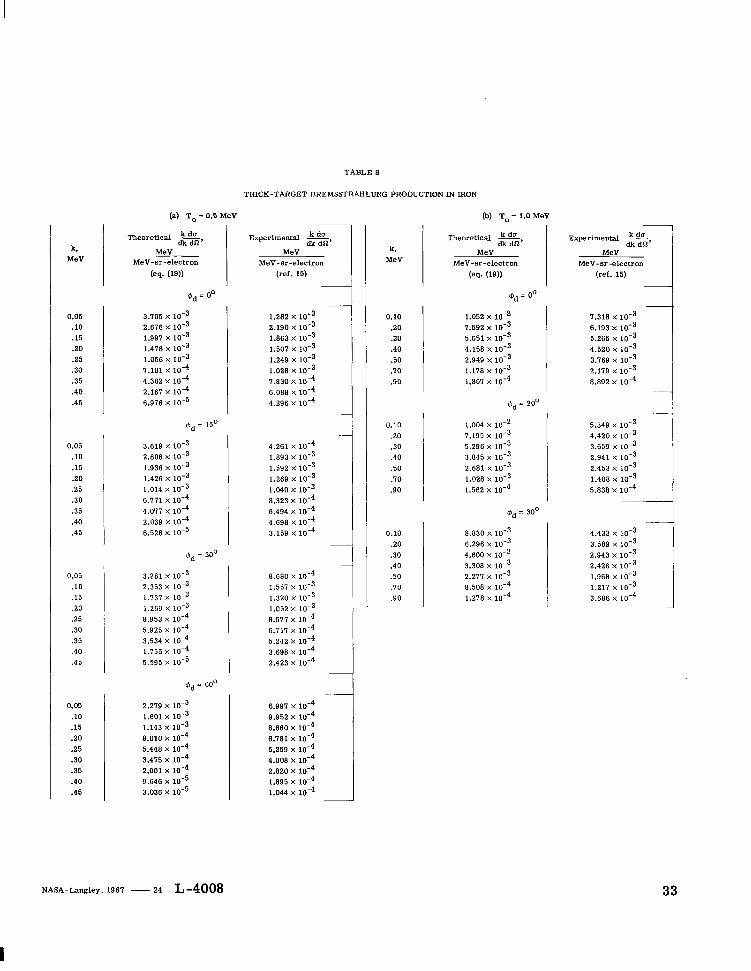
The comparisons of the theoretically predicted resul ts (eq. (19)) with the experi- mental data for -aluminum and iron thick targets and electron kinetic energies of 0.5 and 1.0 MeV are shown in tables 7 and 8 and figures 9 and 10. Each table is
oE
-1
I eriment (ref. !ory (eq. (19))
0 .1 .2 .3 .4 .5 Photon energy, k, MeV
Figure 9.- Thick-target bremsstrahlung pro- duction in aluminum. To = 0.5 MeV; detector angle, 00.
I I I I o Experiment (ref. 15)
ieory
~
Q
\ \
. (19
Q
\ ~
.4 .6 .8 1.0 Photon energy, k, MeV
Figure 10.- Thick-target bremsstrahlung pro- duction i n iron. To = 1.0 MeV; detector angle, @.
20
I

representative of the thick-target bremsstrahlung production for a specific material, electron kinetic energy, and detector angle.
The values presented in tables 7(a) and 8(b) for Qd = 0' are plotted in figures 9 and 10 to show the general trend of comparison. Here the bremsstrahlung intensity is a function of the photon energy, detector angle, electron kinetic energy, and material. The theoretical results (obtained from evaluating eq. (19)) compare favorably with the exper - imental data over most of the photon energy range. The discrepancy that exists between the theoretical and experimental data is expected, inasmuch as the Born approximation technique is used in the theoretical thick-target model. The reason for this discrepancy is realized by comparing experimental thin-target data with the Bethe -Heitler theory. Figures 11 and 12 show this comparison for aluminum thin targets, detector angles of 15' and 30°, and incident electron energies of 0.5 and 1.0 MeV, respectively. It is seen from figures 11 and 12 that the Bethe-Heitler theory, in general, overestimates the intensity a t the low photon energies and, as was previously anticipated, underestimates the spectrum in the high frequency region (i.e., upper photon energy range). Because the thick-target spectra are obtained by summing up the spectra for a series of thin targets, the discrep- ancy between the theory and experiment for the thick target is obvious and expected. Thus, the theoretical thick-target results a r e expected to overestimate the spectrum at the low photon energies and underestimate at the high frequency region.
E '
3 0 \a \ e ee c E
m L Y)
~
Experiment (re bet he-Heitler theoretical ~
cross
P
ction
51
0 .1 .2 .3 . 4 . .5
Figure 11.- Thin-target differential cross sections for 0.5-MeV bremsstrahlung at photon energies k and eo = 15O and 300. z = 13.
Photon energy, k, MeV 0
b Experiment (ref. 1 - Bethe-Heitler
theoretical -cross section
)
*
.8 1.0 Photon energy, k, MeV
Figure 12.- Thin-target differential cross sections for 1.0-MeV bremsstrahlung at photon energies k and eo = 15O and 30°. z = 13.
2
21
I

It is important to t ry to estimate the degree of improvement of the theory, as pre- sented herein, over the usual simplified approach (straight through theory) of assuming that the electron suffers no multiple scattering. The equation describing straight through theory is
scattering greatly improves the method for approximating the angular distribution of thick- target bremsstrahlung.
=.
NAZ2 Eo dE (2 1) = A l k + l ( $ e)thin target 1 dE
dt
E 1 0 c u I h
S L VI
I
U Numerical Correction to Thick-Target
Bremsstrahlung Spectrum 10
The use of the Bethe-Heitler thin-target c ross section in equation (19) introduces an unavoidable e r r o r in the thick-target spectrum.
fact that the Bethe-Heitler theory does not pre- The difficulty, as previously stated, l ies in the 10-
~~ - Straight through theory (ea (21)) Multiple scatteFing (I Exoeri m t (ref. 15)
\I
.2 .> .4 Photon energy, k, MeV
dict a result in accordance with experiment. This discrepancy was previously shown in figures 11 and 12.
Figure 13.- Comparison of straight through theory with multiple scattering theory and experiment. Aluminum thick target; To = 0.5 MeV; detector angle, 30'.
The present deficiency in the theoretical prediction of the thin-target c ross section can be attributed almost entirely to the use of plane waves for the electron wave function in the matrix element for the radiative collisions as prescribed by the Born approxima- tion. To improve the theoretical estimates, the Born approximation should be replaced with a formulation which uses electron-Coulomb wave functions. Carbide Research Institute is presently developing for the NASA under Contract No. NASw-1235 the mathematical formulation of the electron bremsstrahlung cross section for unpolarized incident particles by using Coulomb wave functions.
C. D. Zerby of Union
The difficulty with the
22

improved method, and the reason irt has not been used extensively in the past, is that it does not yield a simple analytic formula but requires extensive numerical procedures to obtain results. When Zerby's calculations are available it is presumed that the results can replace the Bethe-Heitler analytic formula in the existing computer program.
Since no exact analytic expression exists for the thin-target c ross section, the next logical approach is to correct for the discrepancy in the Bethe-Heitler relation with a semiempirical or empirical correction. Since in the energy region of the electron rest-mass energy (0.511 MeV) Coulomb corrections (ref. 7) to the Bethe-Heitler expres- sion are not available in analytical form, a correction must be approximated from the limited experimental resul ts available. This correction is made by considering the two following important assumptions:
(a) The major contributions to the region of the intensity spectrum where the largest discrepancy exists (upper region in photon energy) result from electrons with energies near the incident electron energy - that is, electrons that have just entered the incident surface.
(b) The multiple scattering effects have not appreciably modified the electron dis- tribution near the front face of the target.
As a result of making these two assumptions it is possible to use existing thin- target experimental data to correct the thick-target spectrum for some specific cases. In more general t e rms the thick-target spectrum (obtained from eq. (19)) is corrected for its discrepancy with experimental results by multiplying by a correction factor defined as 5 (k). This factor is a function of the photon energy k and atomic number of the target material and represents the number by which the Bethe-Heitler thin-target c ross section must be multiplied so that it agrees with experimental data.
Since a first-approximation correction factor has been defined, equation (19) can be written in the following way
P, s in E de d@ dE 1 A 1 d E ;x A 1 d E ;x (22)
As an illustrative example, equation (22) is used to determine the bremsstrahlung spectrum for a 0.5-MeV electron incident upon an aluminum thick target with a detector angle of 15'. Because of assumption (a) a thin-target spectrum with an incident electron kinetic energy of 0.5 MeV is chosen and because of assumption (b) the angle of observa- tion 8, of the thin-target spectrum is chosen to correspond to the thick-target
23

2
L 0
U m
Y
I
L - is
1
0
4 9
-.
.1 .2 .3 .4 .5 Photon energy, k, MeV
Figure 14.- A plot of c(k) factor for 0.5-MeV electron. Aluminum target; detector angle, 150.
I n - 5 1
I l l Experiment (ref. 15)
.---MultiDle scattering, 1st attering, 2d
1
\ " \ \ I
I" 0 .1 .2 .3 .4 .5 Photon energy, k, MeV
Figure 15.- Comparison of corrected multiple scattering theory (eq. (22)) with multiple scattering theory (eq. (19)) and experiment. Aluminum thick target; To = 0.5 MeV; detector angle, 15O.
)lution lution
detector angle +d, that is, previously presented in figure 11 and the plot of the ((k) factor for this spectrum is shown in figure 14. The results of this example are presented in figure 15 and it must be assumed that similar corrections can be made to all thick-target spectra provided the thin-target data exist for the corresponding electron kinetic energy and observation angle.
@d = eo = 15'. A thin-target spectrum of these angles was
CONCLUDING REMARKS
The complication of multiple electron scattering within a thick absorber makes a rigorous analytical solution difficult for the prediction of the angular distribution of bremsstrahlung from completely stopped electrons. The ref ore , an approximating formula has been presented for predicting the thick-target spectrum which is differen- tial both in photon energy and angle of emission. This approximation is derived from the summation of the contribution from successive thin s t r ips into which the absorber is divided.
The use of the thin-target Born approximation c r o s s section for deriving the thick- target expression introduces an e r r o r that is presently unavoidable.
24

The comparisons between the results obtained from the theory derived herein and experimental data are favorable; thus, it can be concluded that the approximating formula for the angular distribution of electron bremsstrahlung in thick targets is valid and is an improvement over the usual straight through theory.
Langley Research Center, National Aeronautics and Space Administration,
Langley Station, Hampton, Va., December 20, 1966, 124-09-01 - 14 -23.
25

REFERENCES
1. Hess, W. N.: The Artificial Radiation Belt Made on July 9, 1962. J. Geophys. Res., vol. 68, no. 3, Feb. 1, 1963, pp. 667-683.
2. Kramers, H. A.: On the Theory of X-Ray Absorption and of the Continuous X-Ray Spectrum.
3. Wilson, Richard: A Formula for Thick Target Bremsstrahlung.
Phil. Mag., vol. 46, no. 275, Nov. 1923, pp. 836-871.
Proc. Phys. SOC. (London), vol. 66, pt. 7, no. 403 A, July 1, 1953, pp. 638-644.
4. Scott, W. Wayne: Electron-Bremsstrahlung Differential Cross Sections for Thin and Thick Targets. NASA TN D-2659, 1965,
5 . Berger, Martin J.: Monte Carlo Calculation of the Penetration and Diffusion of Fast Charged Particles. Methods in Computational Physics, Vol. 1 - Statistical Physics, Berni Alder, Sidney Fernbach, and Manuel Rotenberg, eds., Academic Press , 1963, pp. 135-215.
6. Heitler, W.: The Quantum Theory of Radiation. Third ed., Clarendon Press (Oxford), 1954, pp. 242-256 and 418.
7. Koch, H. W.; and Motz, J. W.: Bremsstrahlung Cross-Section Formulas and Related Data. Rev. Mod. Phys., vol. 31, no. 4, Oct. 1959, pp. 920-955.
8. Goudsmit, S.; and Saunderson, J. L.: Multiple Scattering of Electrons. Phys. Rev., Second ser., vol. 57, no. 1, Jan. 1, 1940, pp. 24-29.
9. Spencer, L. V.: Theory of Electron Penetration. Phys. Rev., Second ser., vol. 98, no. 6, June 15, 1955, pp. 1597-1615.
10. Wright, Kenneth A.; and Trump, John G.: Back-Scattering of Megavolt Electrons From Thick Targets. J. Appl. Phys., vol. 33, no. 2, Feb. 1962, pp. 687-690.
11. Evans, Robley D.: The Atomic Nucleus. McGraw-Hill Book Co., Inc., c.1955.
12. Bethe, Hans A.; and Ashkin, Julius: Passage of Radiations Through Matter. Experimental Nuclear Physics, Vol. I, E. Segr6, ed., John Wiley & Sons, Inc., c.1953, pp. 166-357.
13. Blizard, Everitt P.; and Abbott, Lorraine S., eds.: Shielding. Vol. 111, Pt. B of Reactor Handbook, Second ed., Interscience Publ., 1962, p. 115.
26

14. Baggerly, L. L.; Dance, W. E.; Farmer B. J.; and Johnson, J. H.: Bremsstrahlung Production in Thick Aluminum and Iron Targets by 0.5- to 3.0-MeV Electrons. Second Symposium on Protection Against Radiations in Space, Arthur Reetz, Jr., ed., NASA SP-71, 1965, pp. 449-453.
15. Dance, William E.; Baggerly, Leo L.; Rester, David H.; and Rainwater, Walter J., Jr.: Investigations of Electron Interactions With Matter. NASA CR-334, 1965.
27

TABLE 1
ANGULAR DISTRIBUTION O F MULTIPLE SCATTERED
ELECTRONS IN ALUMINUM
(a) Electron energy reduced from To = 0.5 MeV
0.10
P, for T, MeV, of - E,
deg
0 15 30 45 60 75 90
105 120 135 150 165 180
~
0.30 0.15 0.05 0.40 0.35 0.45
2.0060 1.5810
.a200
.3186
.1120
.0420
.oia9
.0100
.0059
.0046
.0036
.003 1
.0030
0.25
0.8200
.59a4
.7760
.3973
.2330
.1276
.0683
.0382
.0233
.0152
.0110
.0097
.009 2
0.20
0.6290 .5921 .4993 .3703 .2501 .1590 .0960 .0553 .0372 .0251 .oiao .0155 .0148
1.6200 1.3500
.7880
.3510
.1390
.0540
.0240
.0120
.0080
.0054
.0045
.003b
.0037
1.3500 1.1700 ,7500 .3850 .1700 .0745 .0340 .0180 .0100 .0075 .0059 .0050 .0049
1.0800 .9580 .6750 .3960 .2020 .0980 .0450 .0250 .0150 .0100 ,0078 .0067 .0064
0.4520 .4352 .3634 .3160 .2271 .1783 .12ao .0890 .0627 .0448 .0330 .0290 .0279
0.3100 .3001 .2a57
.2233
.1860
.1551
.1242
.lo07
.oa30
.0710
.0656
.0628
0.1987 .1a02
.1a94
.1920
.1802. ,1740 ,1561 .1506 .1442 .1381 .1383 .1359 .1350
(b) Electron energy reduced from To = 1.0 MeV
P, fo r T, MeV, of - 0.9 0.7 0.5 0.4 0.3 0.2 0.1 0.8 0.6
1.6831 1.4105
.8542
.4035
.1661 ,0679 ,0307 .0161 .ooga .0069 .0054 .0047 .0045
0 15 30 45 60 75 90
105 120 135 150 165 180
2.4786 1.7000
.6276
.1729
.0497
.0179
.0082
.0046
.0030
.0022
.0018
.0016 ,0015
2.2069 1.6318
.72 10
.2352
.0735
.0267
.0120
.0066
.0042
.0030
.0025
.0022 ,002 1
1.9412 1.5361
.a004
.3133
.1108
.04ia
.oia6
.0099
.0062
.0044
.0036
.003 1
.0030
1.4288 1.2564
.a704
.4927
.2422
.1129
.0537
.0283 ,0169 .0115 .ooa9 .0076 .0073
1.1801 1.0771
m a 2 .5572 .3310 .1826 .0983 .0547 .0330 .0220 .0165 .0140 .0133
0.9220 .8737 .7451 .5735 ,4090 .2717 .1736 .io98 .0713 .049 1 .036a ,0308 .0290
0.6613 .6433 .5909 ,5158 .4286 .3426 .2657 .2026 ,1545 .1202 .0980 . o a ~ .0817
0.4119 .4087
.3827 ,3624 .3395 .3154 .2926 ,2716 .2539 .24 05 .2323 .2297
.39a6
28
d&
0 15 30 45 60 75 90 105 120 135 150 165 180
E , deg
0 15 30 45 60 75 90 105 120 135 150 165 180
0.45
1.2476 1.1301 .8453 .5379 .3051 .1618 .0854 .0474 .0289 .0197 .0150 .0128 .0121
~ ~_____
0.9
1.6045 1.3618 .8573 .4286 .1904 .0827 .039 0 .0207 .0127 .0089 .0069 .0069 .0058
TABLE 2
ANGULAR DISTRIBUTION O F MULTIPLE SCATTERED
ELECTRONS IN IRON
(a) Electron energy reduced from To = 0.5 MeV
P, for T, MeV, of -
0.40
1.1145 1.0324 .8153 .5644 .3488 .2021 .1143 .0665 .0411 .0279 .0211 .0179 .0169
0.35
0.9866 -9298 .7696 .5733 .3884 .2469 .1518 .0935 .0599 .0413 .0313 .0264 .0249
0.30
0.8619 .8177 .7127 .5635 .4182 .2917 .1961 .1304 .0884 .0629 .0485 .0411 .0388
0.25
0.7264 .7029 .6326 .5377 .4299 ,3280 .2425 .1769 .1294 .0978 .OW9 .0673 .0638
0.20
0.5953 .5818 .5428 .4854 .4170 .3474 .2820 .2381 .1813 .1483 .1257 ,1129 .lo86
~
0.15
0.4741 .4678 .4495 .4218 .3865 .3480 .3089 .2724 .2408 .2150 .1961 .1847 .1809
(b) Electron energy reduced from To = 1.0 MeV
0.8
1.4244 1.2505 .7928 .4886 .2451 .1167 .0571 .0309 .0187 .0129 .0100 .0086 .0082
0.7
1.2452 1.1275 .8468 .5388 ,3061 .1625 .0855 .0475 .0290 .0197 .0150 .0128 .0121
P, for T, MeV, of - - 0.6
1.0710 .99 17 .8032 .5702 .3649 .2186 .1274 .0753 .0471 .0321 .024 3 .0205 .0194
0.5
0.8953 .8519 .7271 .5697 .4113 .2794 .1828 .1188 .0786 .0553 .0424 .0358 .0338
0.4
0.7227 ,6992 .6287 .5370 .4301 .3296 .2444 .1786 .1310 .0987 .0787 .0681 .0646
0.3
0.5563 .5451 .5141 .4669 .4104 .3508 .2937 .24 34 .2011 .1695 .147 1 .1341 .1297
0.10
0.3724 .3704 .3647 .3564 .3450 .3316 .3176 .3042 .2915 .2807 .2724 .2673 .2660
0.05
0.3221 .3214 .3214 .3208 .3202 .3189 .3183 .3176 .3164 .3157 .3151 .3151 .3144
0.2
0.4092 .4061 .3965 .3806 .3616 .3393 .3158 .2936 .2726 .2554 .2427 .2345 .2319
~
0.1
0.3263 .3256 .3250 .3237 ,3224 .3205 .3180 .3160 .3141 .3129 .3116 .3110 .3103
29
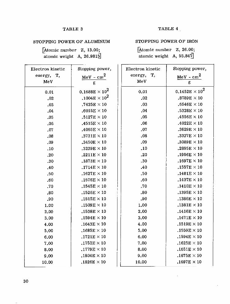
TABLE 3 TABLE 4 .
STOPPING POWER O F ALUMINUM
p t o m i c number Z, 13.00; atomic weight A, 26.98157
Electron kinetic energy, T,
MeV
0.01 .02 .03 .04 .05 .06 .07 .08 .09 .10 .20 .30 .40 .50 .60 .70 .80 .90
1.00 2.00 3.00 4.00 5.00 6.00 7.00 8.00 9.00
10.00
~
Stopping power, 2 MeV - cm
g
0.16883 X lo2 . lo043 X lo2 .74253 X 10 .6015E X 10 ,51273 X 10 .4515E X 10 .4065E X 10 .3721E X 10 .345OE X 10 .32293 X 10 .2211E X 10 .18733 X 10 .1714E X 10 ,16273 X 10 .1576E X 10 .1545E X 10 .15263 X 10 .1515E X 10 .1509E X 10 .1538E X 10 .1594E X 10 .1643E X 10 .16853 X 10 .1721E X 10 .1752E X 10 ,17793 x 10 .1804E X 10 .1826E X 10
STOPPING POWER OF IRON
b t o m i c number Z, 26.00; atomic weight A, 55.84g
~
Electron kinetic energy, T,
MeV
0.01 .02 .03 .04 .05 .06 .07 .08 .09 .10 .20 .30 .40 .50 .60 .70 .80 .90
1.00 2.00 3.00 4.00 5.00 6.00 7.00 8.00 9.00
10.00
Stopping power, 2 MeV - cm
g
0.14523 X lo2 .87893 X 10 .6546E X 10 .5328E X 10 .45563 X 10 .40223 X 10 .36293 X 10 .33273 X 10 .30893 X 10 .2895E X 10 .19963 X 10 .16973 X 10 .15573 x 10 .1481E X 10 .14373 X 10 .1410E X 10 .1395E X 10 .1386E X 10 .1381E X 10 .1416E X 10 .1471E x 10 .1519E X 10 ,15593 X 10 .1594E x 10 .1625E X 10 .1651E X 10 .16753 X 10 .16973 X 10
30

k, MeV
10.00E X
2.00E X 10-1 3.00E X 10-1 4.00E X 10-1 5.00E X 10-1 6.00E X 10-1 7.00E X 10-1 8.00E X 10-1 9.00E X 10-1 1.OOE 1.50E 2.00E 3.00E 4.00E 5.00E 6.00E 7.00E 8.00E 9. OOE 1.00E X 10
k, MeV
10.00E X
2.00E X 10-l 3.00E X 10-1 4.00E X 10-1 5.00E X lo-' 6.00E X 10-1 7.00E X 10-1 8.00E X 10-1 9.00E X 10-1 1.00E 1.50E 2.00E 3.00E 4.00E 5.00E 6.00E 7.00E 8.00E 9.00E 1.00E X 10
TABLE 5
ATTENUATION AND BUILDUP COEFFICIENTS FOR ALUMINUM
Pm? cm2/g
8.00E 8.00E 8.00E 8.00E 8.00E 8.00E 8.00E 8.00E 8.00E 8.00E 6.753 5.50E 4.50E 3.80E 3.40E 3.10E 2.70E 2.30E 2.273 2.253
A1
1.69E X lo-' 1.22E X 10-1 1.04E X lo-' 9.30E X lo-' 8.40E X lo-' 7.80E X lo-' 7.30E X lo-' 6.80E X
6.50E X lo-' 6.10E X lo-' 5.00E X lo-' 4.30E X lo-' 3.50E X lo-' 3.10E X lo-' 2.80E X lo-' 2.60E X lo-' 2.50E X
2.40E X lo-' 2.30E X
2.30E X
al
-1.10E X 10-1 -1.lOE X 10-1 -1.1OE X 10-1 -1.lOE X 10-1 -1.lOE X 10-1 -1.lOE X 10-1 -1.lOE X 10-1 -1.lOE X 10-1 -1.lOE X 10-1 -1.lOE X 10-1 -9.40E X lo-' -8.20E X lo-' -7.40E X lo-' -6.60E X lo-' -6.50E X lo-' -6.40E X lo-' -6.30E X
-6.20E X
-6.10E X
-6.00E X
A2
-7.00E -7.00E -7.00E -7.00E -7.OOE -7.00E -7.00E -7.00E -7.00E -7.00E -5.753 -4.50E -3.50E -2.8OE -2.40E -2.10E -1.70E -1.30E -1.27E -1.25E
TABLE 6
ATTENUATION AND BUILDUP COEFFICIENTS FOR IRON
pml
cm2/g
3.443 X 10⁻¹ 1.38E X 10-1 1.06E X 10-1 9.19E X
8.283 X
7.623 X
7.00E X
6.643 X
6.20E X
5.953 X
4.60E X lo-' 4.20E X
3.60E X lo-' 3.30E X
3.10E X lo-' 3.04E X lo-' 3.00E X lo-' 2.953 X
2.953 X lo-' 2.943 X lo-'
A1
1.17E X 10 1.11E X 10 1.07E X 10 1.03E X 10 1.00E X 10 9.70E 9.40E 9.10E 8.80E 8.60E 7.50E 6.60E 5.00E 4.00E 3.453 3.10E 2.80E 2.50E 2.253 2.00E
al
-9.90E X
-9.80E X
-9.70E X
-9.60E X
-9.50E X
-9.40E X
-9.20E X
-9.00E X
-8.953 X lo-' -8.80E X lo-' -8.00E X lo-' -7.30E X
-7.20E X
-7.40E X lo-' -7.70E X
-8.00E X
-8.40E X lo-' -8.753 X lo-' -9.10E X lo-' -9.50E X lo-'
A2
-1.07E X 10 -1.01E X 10 -9.70E -9.30E -9.00E -8.70E -8.40E -8.10E -7.80E -7.60E -6.50E -5.60E -4.00E -3.00E -2.453 -2.10E -1.80E -1.50E -1.25E -1.00E
a2
4.40E X lo-' 4.40E X
4.40E X lo-' 4.40E X lo-' 4.40E X lo-' 4.40E X lo-' 4.40E X lo-' 4.40E X
4.40E X lo-' 4.40E X lo-' 6.90E X
9.30E X lo-' 1.16E X 10-1 1.30E X 10-1 1.41E X 10-1 1.52E X 10-1 1.50E X 10-1 1.50E X 10-1 1.39E X 10-1 1.28E X 10-1
a2
0 4.00E x 7.00E x
1 0 . 0 0 ~ x 1.25E X
1.75E X
1.9OE X lo-' 2.253 X
2.60E X
2.80E X lo-' 4.00E X lo-' 4.90E X lo-' 6.20E X lo-' 6.70E X lo-' 6.50E X lo-' 5.90E X
4.753 X
3.50E X
2.253 X lo-' 1 0 . 0 0 ~ x
31
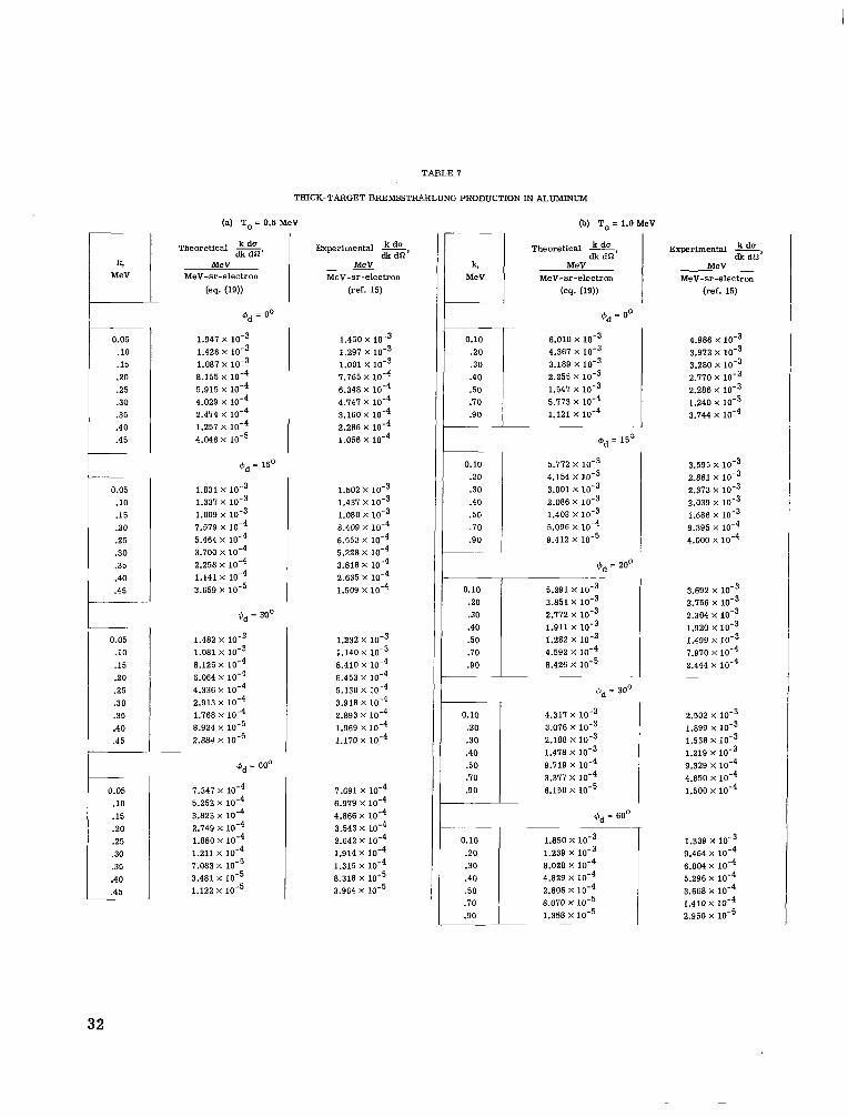
TABLE I
THICK-TARGET BREMSSTRAHLUNG PRODUCTION IN ALUMINUM
__
4 MeV
0.05 .10 .15 .20 2 5 .30 .35 .40 .45
__ 0.05 .10 .15 .20 2 5 .30 .35 .40 .45
_ _ ~ -
___ 0.05
.10
.15 20 .25 .30 .35 .40 .45
0.05 .10 .15 20 2 5 .30 .35 .40 .45 __
(a) To = 0.5 MeV
MeV MeV-sr-electron
(eq. (19))
Qd= 00 ' 1.941 x 1.426 X loF3 1.081 8.155 x 5.915 X 4.029 x 2.414 X
1.257 4.046 x
Qd = 15'
1.831 x
1.009 1.337 x
7.579 x 5.464 X
3.100 x 2.258 x 1.141 X
3.659 X
Qd = 30'
1.482 1.081 x 8.125 x 6.064 X
4.336 X
2.913 X l o e 4 1.768 X
8.924 2.884 x
bd = 60'
1.347 x 5.252 x
2.149 x 3.823
1.880 x 1.211
3.481 x 1.122 x
1.083 X
Experimental kdo dk dSl'
MeV MeV-sr-electron
(ref. 15)
1.450 X
1.291 x 1.001 x
6.348 x
2.286 x
1.165 X
4.141 X
3.160 X
1.056 X
1.502 X
1.437 X
1.080 x 8.409 x 10.~
5.228 x 3.816 x
6.553 X
2.635 X
1.509 X
1.232 X
1.140 X
8.410 x
3.918 x 2.893 x 10.~
6.453 X
5.130 X
1.969 X
1.170 X
7.691 X
6.919 X
4.866 x 10-~ 3.543 x 2.642 X
1.914 X
1.315 X
8.318 x 3.964 X
0.10 20 .30 .40 .50 . I O .90
0.10 20 .30 .40 .50 . I O
.90
0.10 2 0 .30 .40 .50 . I O .90
0.10 .20 .30 .40 .50 . I O .90
0.10 .20 .30 .40 .50 . I O .90
6) To= 1.0 MeV
Theoretical =, dk dCl
MeV MeV-sr-electron
(eq. (19))
$Id = 00
6.010 X
4.361 x 3.189 x 2.255 X
1.547 X
5.713 X
1.121 x 10.~
Qd = 15'
5.772 X
4.154 x
2.086 x 1.408 x 1 0 - ~
3.001 X
5.096 X
9.412 X
bd = 200
5.291 X
3.851 x 10'~ 2.172 x 1 0 - ~ 1.911 x 10-~ 1.282 x 1 0 - ~
8.426 x 1 0 - ~ 4.592 X
dd = 30'
4.311 X
3.076 X
2.188 x 10.~
9.119 x 1 0 - ~ 1.418 X
3.377 X
6.150 X
bd = 60'
1.850 x
8.028 x 4.829 x 2.806 x 1 0 - ~ 8.070 x 1.358 x
1.239 X
Experimental = dk do'
MeV MeV-sr-electron
(ref. 15)
4.986 x 10⁻³
3.280 x 10⁻³
2.286 10-3
3.744 x 10.~
3.913 X
2.170 X
1.240 X
3.595 x 2.861 x
1.686 x 10-3 9.395 x 10⁻⁴
2.313 X
2.039 X
4.000 X
3.692 X
2.156 X
2.304 X
1.499 X l o e 3 1.920 x
1.910 x 1 0 - ~ 2,444 X
2.502 X
1.899 x
1.219 1.536 X
9.329 X
4.650 X
1.500 X
1.339 X
9.464 X
6.804 x
3.668 x 5.296 X
1.410 X
2.950 X
32
k, MeV
0.05 .10 .15 2 0 2 5 .30 .35 .40 .45
0.05 .10 .15 20 2 5 .30 .35 .40 .45
0.05
.10
.15
.20
.25
.30
.35
.40
.45
0.05 .10 .15 20 2 5 .30 .35 .40 .45
(a) To = 0.5 MeV
Theoretical =, MeV
MeV-sr-electron
(es. (19)) I cpd = 00
3.705 x lob3 2.676 X
1.997 X lob3 1.478 x 10⁻³ 1.056 x 7.101 X
4.302 X
2.167 x 6.976 X
m d = 15'
3.619 X
2.606 x 1.936 X
1.426 X
1.014 x 6.111 X
4.077 X
2.039 x low4 6.526 x
bd = 30'
3.281 x 1 0 ' ~ 2.353 x 1.737 X
1.269 X
8.953 x
3.534 x
5.595 x
5.925 X
1.755 X
md = 60'
2.279 x 1.601 X
1.143 X
8.010 x 10-4 5.448 x 10⁻⁴ 3.475 x 2.001 x 9.646 x 3.036 X
TABLE 8
THICK-TARGET RREMSSPFUUILUNG PRODUCTION IN IRON
-
Experimental a dk dn
MeV MeV-sr-electron
(ref. 15) -
1.282 x 10⁻³ 2.190 x 10⁻³ 1.863 x 10⁻³
1.028 x 10⁻³ 7.830 x 6.088 x 10'~
1.507 X
1.249 x
4.296 X low4
4.261 X
1.893 x 1.592 X
1.269 X
1.040 X
8.323 x
4.698 x 6.494 X
3.159 X
8.680 x 1.557 X
1.320 X loe3 1.052 x 8.577 x 10-4 6.717 x 5.242 X
3.698 x 2.423 X
6.997 x 10.~
8.660 x 6.781 x
4.008 x 10-4 2.820 x 1.895 x
9.952 X
5.259 X loT4
1.044 X
k, MeV
0.10 2 0 .30 .40 .50 .70 .90
0.10 .20 .30 .40 .50 .70 .90
0.10 2 0 .30 .40 .50 .70 .90
0) To= 1.0 MeV
Theoretical -, dk dS2
MeV MeV-sr-electron
(es. (19))
@d = 00
1.052 x lo-' 7.592 x 5.651 x 4.158 x 10-3
1.118 x 10⁻³ 1.867 x
2.949 x
bd = 200
1.004 x 10.' 1.195 x 5.296 x 3.845 x 2.681 x 10-3 1.028 x 10⁻³ 1.562 x
md = 30'
8.830 x
3.308
8.508 x 1.218
6.296 x 4.600 x
2.271 x
Experimental *, MeV
MeV-sr-electron (ref. 15)
dk dn
-
7.318 x 10⁻³ 6.193 x 5.265 x low3 4.520 x 3.769 x 2.179 x 8.892 x
~~
5.349 x 4.420 x 3.659 x 2.941 x 2.453 x 1.408 x 5.838 x
4.433 x 3.589 x 10-3 2.943 x 2.426 X
1.968 x
3.686 x 1.217 X
NASA-Langley, 1967 ~ 24 L-4008 33

“The aeronatrtical and space activities of the United States shall be conducted so as to contribute . . . to the expansion of human knowl- edge of phenomena in the atmosphere and space. The Administration shall provide for the widest practicable and appropriate dissemination of information concerning its actiuifies and the results tbereof .”
-NATIONAL hRONAUTICS AND SPACE ACT OF 1958
NASA SCIENTIFIC AND TECHNICAL PUBLICATIONS
TECHNICAL REPORTS: Scientific and technical information considered important, complete, and a lasting contribution to existing knowldge.
TECHNICAL NOTES: Information less broad in scope but nevertheless of importance as a contribution to existing knowledge.
TECHNICAL MEMORANDUMS: Information receiving limited distribu- tion because of preliminary data, security classification, or other reasons.
CONTUCTOR REPORTS: Scientific and technical information generated under a NASA contract or grant and considered an important contribution to existing knowledge.
TECHNICAL TRANSLATIONS: Information published in a foreign language considered to merit NASA distribution in English.
SPECIAL PUBLICATIONS: Information derived from or of value to NASA activities. Publications include conference proceedings, monographs, data compilations, handbooks, sourcebooks, and special bibliographies.
TECHNOLOGY UTILIZATION PUBLICATIONS: Information on tech- nology used by NASA that may be of particular interest in commercial and other non-aerospace applications. Publications include Tech Briefs, Technology Utilization Reports and Notes, and Technology Surveys.
Details on the availability of these publications may be obtained from:
SCIENTIFIC AND TECHNICAL INFORMATION DIVISION
N AT1 0 N A L AE R 0 N A U TI CS AND SPACE AD M I N I STR AT1 0 N
Washington, D.C. PO546