annex. annex. 6.1 brief design of cross flow turbine...
TRANSCRIPT

- 6-29 -
Study on Rural Energy Supply with Utilization of Renewable Energy in Rural Areas in the Republic of Indonesia
Manual for Micro-hydro power Development Chapter 6 ANNEX 1
ANNEX.
Annex. 6.1 Brief Design of Cross Flow Turbine (SKAT T-12, 13 &14) 1. Cross Flow Turbine
Cross flow turbine is a suitable turbine for micro power plants in Indonesia at present stage. SKAT T-12,
T-13 and T-14 are recommended to be adopted as the cross flow turbine for micro-hydro power
generation.. The main advantages are as follows:
• Enough technical data for design is available in Indonesia with model testing.
• Proper design with a wide range of heads and flows according to available actual site conditions.
• Comparably low cost
• Comparably short delivery time
• Easy installation
• Local fabrication, maintenance and repair in Indonesia
2. Fundamental Design data
The following fundamental data shall be obtained from civil design.
1. Elevation of water level at forebay _______ m
2. Elevation of turbine center _______ m
3. Elevation of tailrace water if required _______ m
4. Rated flow (discharge) _______ m3/s
5. Internal diameter of penstock _______ cm
6. Length of penstock _______ m
7. Condition of nos. and bends of penstock, etc.
3. Application Limits
The applicable limit of cross flow turbine (T-12, T-13 & 14) can be summarized in the following Table
6.A1.1.
Table 6.A1.1 Limit of Cross Flow Turbine (at turbine shaft)
Unit Lower limit Upper limit
Hnet Net head m 4 50
Q Discharge (Flow) l/s 100 820
P Shaft power output kW 10 250
bo Inlet width mm 100 1120
Number of intermediate discs - 0 8
Note: These limits must be respected. Engineering consideration such as practicability, relative cost,
tightness of inlet valve in closed position, opening force on inlet valve, strength of the rotor
blades, strength of the connection of the side discs to the rotor shaft, diameter of the shaft etc
demand that these limits be respected.

- 6-30 -
Study on Rural Energy Supply with Utilization of Renewable Energy in Rural Areas in the Republic of Indonesia
Manual for Micro-hydro power Development Chapter 6 ANNEX 1
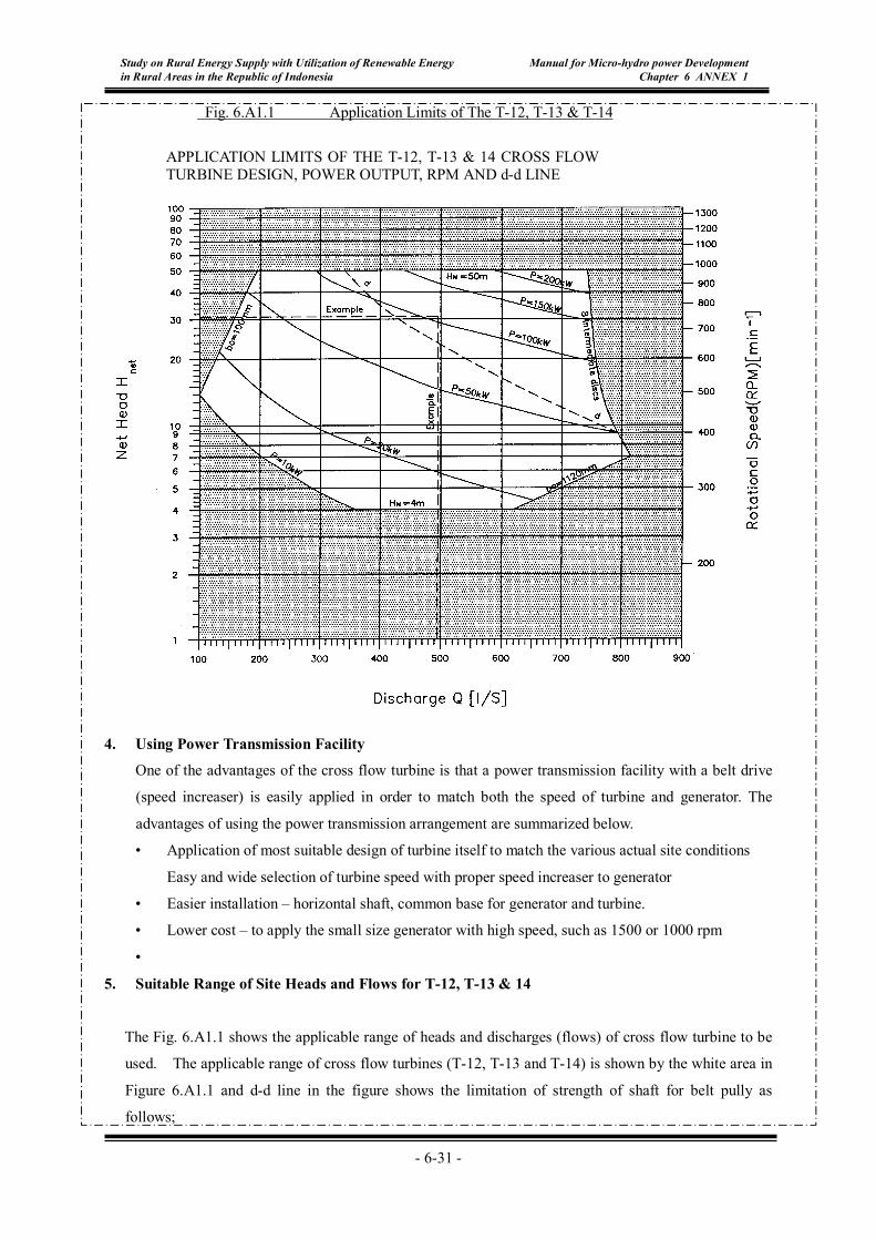
On Chart 1 curves are shown for various outputs P. The corresponding formula is :
η⋅⋅⋅= netHQP 8.9
The approximate rotational speed n of the turbine can be read from the vertical scale on the right side of
Chart 1. Its exact value is calculated with following formula for T-12, 13 & 14:
netHn 133=
Example within the limits:
For a net head Hnet =30.89 m and a discharge Q=497 l/s, the following values can be determined on the
T-13 and T-14 application Fig. 6.A1.1.
The point of intersection of the Hnet and Q values is within the range of the white field, which means
that the T-13 and T-14 design is appropriate.
The shaft power output is just above 100 kW.
The rotational speed n is about 740 min-1.
Example outside the limits
Hnet = 6m and Q = 200 l/s
Although both Hnet and Q are within the limits, the intersection point on Fig. 6.A1.1 lies outside the
white, non-dotted field. For this application T-12, T-13 and T-14 cannot be used.
Please refer to Fig. 6.A1.1 in next page
- 6-31 -
Study on Rural Energy Supply with Utilization of Renewable Energy in Rural Areas in the Republic of Indonesia
Manual for Micro-hydro power Development Chapter 6 ANNEX 1
Fig. 6.A1.1 Application Limits of The T-12, T-13 & T-14
APPLICATION LIMITS OF THE T-12, T-13 & 14 CROSS FLOW TURBINE DESIGN, POWER OUTPUT, RPM AND d-d LINE
4. Using Power Transmission Facility
One of the advantages of the cross flow turbine is that a power transmission facility with a belt drive
(speed increaser) is easily applied in order to match both the speed of turbine and generator. The
advantages of using the power transmission arrangement are summarized below.
• Application of most suitable design of turbine itself to match the various actual site conditions
Easy and wide selection of turbine speed with proper speed increaser to generator
• Easier installation – horizontal shaft, common base for generator and turbine.
• Lower cost – to apply the small size generator with high speed, such as 1500 or 1000 rpm
•
5. Suitable Range of Site Heads and Flows for T-12, T-13 & 14
The Fig. 6.A1.1 shows the applicable range of heads and discharges (flows) of cross flow turbine to be
used. The applicable range of cross flow turbines (T-12, T-13 and T-14) is shown by the white area in
Figure 6.A1.1 and d-d line in the figure shows the limitation of strength of shaft for belt pully as
follows;
- 6-32 -
Study on Rural Energy Supply with Utilization of Renewable Energy in Rural Areas in the Republic of Indonesia
Manual for Micro-hydro power Development Chapter 6 ANNEX 1
(1) Intersection point below d-d line
Any transmission system between turbine and generator is permissible
(2) Intersection point above d-d line
Additional bending stress on the rotor shaft due to force created by e.g. belt tension is not
permissible, therefore, no belt pulley on the rotor shaft is allowed. In case of a belt transmission,
a separately supported pulley shaft would have to be coupled to the rotor shaft.
The range of cross flow turbine can be extended by using either a four-pole (1500 rpm) or a six-pole
(1000 rpm) generator.
6. Calculation of turbine design
The formulae for the calculation of the turbine performance values in design are as follows;
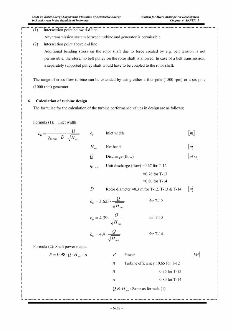
Formula (1): Inlet width
netHQ
Dqb ⋅
⋅=
max110
1 0b Inlet width [ ]m
netH Net head [ ]m
Q Discharge (flow) [ ]sm /3
max11q Unit discharge (flow) =0.67 for T-12
=0.76 for T-13
=0.80 for T-14
D Rotor diameter =0.3 m for T-12, T-13 & T-14 [ ]m
netH
Qb ⋅= 623.30 for T-12
netH
Qb ⋅= 39.40 for T-13
netHQb ⋅= 9.40 for T-14
Formula (2): Shaft power output
η⋅⋅⋅= netHQP 98.0 P Power [ ]kW
η Turbine efficiency : 0.65 for T-12
η 0.76 for T-13
η 0.80 for T-14
Q & netH : Same as formula (1)
- 6-33 -
Study on Rural Energy Supply with Utilization of Renewable Energy in Rural Areas in the Republic of Indonesia
Manual for Micro-hydro power Development Chapter 6 ANNEX 1
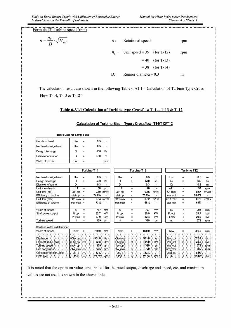
Formula (3) Turbine speed (rpm)
netHDnn ⋅= 11 n : Rotational speed rpm
11n : Unit speed = 39 (for T-12) rpm
= 40 (for T-13)
= 38 (for T-14)
D: Runner diameter= 0.3 m
The calculation result are shown in the following Table 6.A1.1 “ Calculation of Turbine Type Cross
Flow T-14, T-13 & T-12 ”
Table 6.A1.1 Calculation of Turbine type Crossflow T-14, T-13 & T-12
It is noted that the optimum values are applied for the rated output, discharge and speed, etc. and maximum
values are not used as shown in the above table.
����������������������������������������������������������������������������������������������������������������������������������������������������������������������������������������������������������������������������������������������������������������������������������������������������������������������������������������������������������������������������������������������������������������������������������������������������������������������������������������������������������������������������������������������������������������������������������������������������������������������������������������������������������������������������������������������������������������������������
����������������������������������������������������������������������������������������������������������������������������������������������������������������������������������������������������������������������������������������������������������������������������������������������������������������������������������������������������������������������������������������������������������������������������������������������������������������
����������������������������������������������������������������������������������������������������������������������������������������������������������������������������������������������������������������������������������������������������������������������������������������������������������������������������������������������������������������������������������������������������������������������������������������������������������������
Geodedic head Hgeo = 9.5 m
Net head /design head Hnet = 8.5 m
Design discharge Qt = 530 l/sDiameter of runner Dt = 0.30 m
Width of nozzle bno = mm
Net head /design head Hnet = 8.5 m Hnet = 8.5 m Hnet = 8.5 mDesign discharge Qt = 530 l/s Qt = 530 l/s Qt = 530 l/sDiameter of runner Dt = 0.3 m Dt = 0.3 m Dt = 0.3 mUnit speed (opt) n11 = 38 rpm n11 = 40 rpm n11 = 39 rpmUnit flow (opt) Q11opt = 0.80 m^3/s Q11opt = 0.76 m^3/s Q11opt = 0.67 m^3/sEfficiency of turbine etat opt = 74.0% - etat opt = 70.0% - etat opt = 65.0% -Unit flow (max) Q11 max = 0.94 m^3/s Q11 max = 0.82 m^3/s Q11 max = 0.72 m^3/sEfficiency of turbine etat max = 73% - etat max = 68% - etat max = 63% -
Width of runner b0 = 757 mm b0 = 797 mm b0 = 904 mmShaft power output Pt opt = 32.7 kW Pt opt = 30.9 kW Pt opt = 28.7 kW
Pt max = 37.9 kW Pt max = 32.4 kW Pt max = 29.9 kWTurbine speed nt = 369 rpm nt = 389 rpm nt = 379 rpm
If turbine width is determinedWidth of runner b0w = 760.0 mm b0w = 800.0 mm b0w = 900.0 mm
Discharge Qtw_opt = 531.8 l/s Qtw_opt = 531.8 l/s Qtw_opt = 527.4 l/sPower (turbine shaft) Ptw_opt = 32.8 kW Ptw_opt = 31.0 kW Ptw_opt = 28.6 kWTurbine speed ntw_opt = 369 rpm ntw_opt = 389 rpm ntw_opt = 379 rpmRun away speed ntw_max = 665 rpm ntw_max = 700 rpm ntw_max = 682 rpmGenerator/Transm. Effic. eta_g = 83% - eta_g = 83% - eta_g = 83% -El. Output Pel = 27.32 kW Pel = 25.84 kW Pel = 23.80 kW
Turbine T13Turbine T14 Turbine T12
Calculation of Turbine Size Type : Crossflow T14/T13/T12
Basic Data for Sample site