anplusinstall bmw e30 s14 140600en - maxx-automotive/us/anplusinstall_bmw_e30_s14... · - flat head...
TRANSCRIPT
Note: This documentation falls under the law of Copyright. Duplication or transmission to others is not authorized, except with explicit permission of MAXX-automotive.
.. .. .. .. .. .. .. .. .. .. .. .. .. ..
ISSUE 14|06|00 ALPHA-N PLUS ASSEMBLING INSTRUCTIONS
Alpha-N plus
Assembling Instructions BMW M3 E30
ASSEMBLING INSTRUCTIONS ALPHA-N PLUS ISSUE 14|06|00 2
ALPHA-N PLUS ASSEMBLING INSTRUCTIONS
TA
BLE
OF
CO
NT
EN
TS
ISSUE 14|06|00 ALPHA-N PLUS ASSEMBLING INSTRUCTIONS
ALPHA-N PLUS ASSEMBLING INSTRUCTIONS
3
Table of Contents
1 Introduction ...................................... ................................................................................. 4
1.1 Disclaimer .................................................................................................................................... 4
1.2 Safety hints .................................................................................................................................. 4
1.3 Assumption .................................................................................................................................. 4
1.4 Delivery ........................................................................................................................................ 4
1.5 Required Tools ............................................................................................................................ 5
2 Installation of the Throttle Potentiometer ........ ................................................................ 6
2.1 Mechanical mounting ................................................................................................................... 6
2.2 Electrical connection .................................................................................................................... 7
2.2.1 New connector (TE-PT3-Kit) ................................................................................................................... 7
2.2.2 Crossover adapter ................................................................................................................................... 8
3 Air Temperature Sensor ............................ ........................................................................ 9
4 Installation Alpha-N Harness ...................... .....................................................................10
4.1 Basics ........................................................................................................................................ 10
4.2 Preparation ................................................................................................................................ 10
4.3 Wiring ........................................................................................................................................ 11
4.3.1 Handling of the Motronic main connector .............................................................................................11
4.3.2 Removal of pins .....................................................................................................................................13
4.3.3 Variants of wire connection ...................................................................................................................13
4.3.4 Wiring of the Alpha-N harness – step by step ......................................................................................13
4.3.5 Double connection.................................................................................................................................15
4.3.6 Connection out of the Motronic main connector ..................................................................................15
4.3.7 System common grounding ..................................................................................................................16
4.4 Placement and mounting of the Alpha-N Module ....................................................................... 17
5 Options ........................................... ..................................................................................18
5.1 Option connector X3 Analog in / Wideband Lambda ................................................................. 18
5.1.1 Wideband-lambda WBO2 .....................................................................................................................19
5.2 Option connector X2 Shift Lights ............................................................................................... 20
6 General wiring Diagram ............................ .......................................................................21
7 Appendix .......................................... ................................................................................22
7.1 Pin- tables .................................................................................................................................. 22
7.1.1 Pin- table of variant up to V1.07 ...........................................................................................................22
7.1.2 Pin- table of variant from V2.00 ............................................................................................................23
8 Notes.............................................. ...................................................................................24

ASSEMBLING INSTRUCTIONS ALPHA-N PLUS ISSUE 14|06|00 4
ALPHA-N PLUS ASSEMBLING INSTRUCTIONS
INT
RO
DU
CT
ION
1 Introduction
1.1 Disclaimer Liability claims against the vendor regarding damage caused by the fitting, application and use of the Alpha-N-Controller Unit provided will be rejected, except in cases of defects in materials and workmanship.
1.2 Safety hints Incorrect wiring of the Alpha-N plus can destroy the Alpha-N Module or the ECU (Motronic) (see 1.1).
1.3 Assumption This manual refers only to the vehicle type BMW M3 E30 and covers all standard engine variants (195hp, 215hp, Evo1, Evo2 and SportEvo). The Alpha-N plus Module acts as an attachment to the OEM (Bosch Motronic) ECU. The Air Temperature Sensor (part of delivery) must be placed in the Air Intake System.
1.4 Delivery
• [1] Alpha-N plus controller unit
• [2] Throttle Position Sensor (TPS) + spacer + bolts + screws
• [3] Air temperature sensor
• [4] Alpha-N main wiring harness
• [5] Adapter harness air temp sensor
• [6] 10 (+2 reserves) crimp sockets TE-AMP Timer (Motronic connector)
• [7] Heat shrink tubing (small) for wire connections outside the Motronic connector
• [8] Heat shrink tubing (medium) for GND-ring-connector
• [9] Ground wire ring connector
• [10] Connector kit for the TPS
• [11] 12 cable ties, medium size (Alpha-N mounting, Cable fixing, …)
• [12] Weave tape
• [13] PS2 extension cable
• [14] USB to serial (RS232) converter
• [15] Pinout tool
• [16] Program CD
• [17] Documentation
Optional • [18] Adapter harness TPS

ISSUE 14|06|00 ALPHA-N PLUS ASSEMBLING INSTRUCTIONS 5
INT
RO
DU
CT
ION
ALPHA-N PLUS ASSEMBLING INSTRUCTIONS
1.5 Required Tools
- ¼-in. ratchet with extension and 10mm socket
- Phillips screw driver (medium size)
- Screw driver Torx 20
- Edge cutter
- Flat head screw driver (small size -> 3mm)
- Pinout tool to remove the sockets of the ECU (Motronic) connector (part of the kit)
- High quality crimping tool for TE-AMP Timer and Power Timer sockets with and without single wire seals.

ASSEMBLING INSTRUCTIONS ALPHA-N PLUS ISSUE 14|06|00 6
ALPHA-N PLUS ASSEMBLING INSTRUCTIONS
INS
TA
LLA
TIO
N O
F T
HE
TH
RO
TT
LE P
OT
EN
TIO
ME
TE
R
2 Installation of the Throttle Potentiometer
2.1 Mechanical mounting The TPS (Throttle Position Sensor [2]) replaces the original throttle position switch. • Unscrew the two throttle switch screws. • Remove the connector from the throttle switch. • Remove the throttle switch from the throttle spindle/shaft.
• Remove the TPS holder part. • Screw bolts on. (may use screw lock). • Shift the spacer over. Use a little sealing at the throttle body side.
ISSUE 14|06|00 ALPHA-N PLUS ASSEMBLING INSTRUCTIONS 7
INS
TA
LLA
TIO
N O
F T
HE
TH
RO
TT
LE P
OT
EN
TIO
ME
TE
R
ALPHA-N PLUS ASSEMBLING INSTRUCTIONS
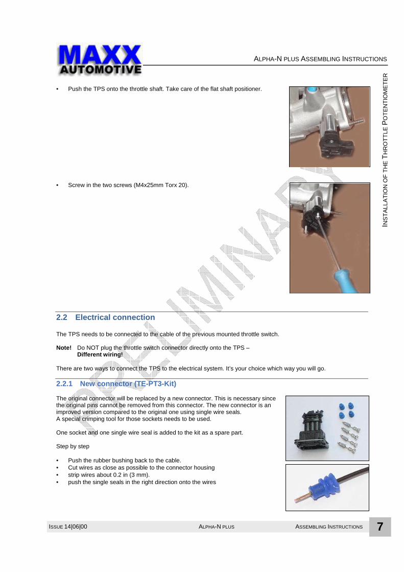
• Push the TPS onto the throttle shaft. Take care of the flat shaft positioner. • Screw in the two screws (M4x25mm Torx 20).
2.2 Electrical connection The TPS needs to be connected to the cable of the previous mounted throttle switch. Note! Do NOT plug the throttle switch connector directly onto the TPS – Different wiring! There are two ways to connect the TPS to the electrical system. It’s your choice which way you will go.
2.2.1 New connector (TE-PT3-Kit) The original connector will be replaced by a new connector. This is necessary since the original pins cannot be removed from this connector. The new connector is an improved version compared to the original one using single wire seals. A special crimping tool for those sockets needs to be used. One socket and one single wire seal is added to the kit as a spare part. Step by step • Push the rubber bushing back to the cable. • Cut wires as close as possible to the connector housing • strip wires about 0.2 in (3 mm). • push the single seals in the right direction onto the wires

ASSEMBLING INSTRUCTIONS ALPHA-N PLUS ISSUE 14|06|00 8
ALPHA-N PLUS ASSEMBLING INSTRUCTIONS
INS
TA
LLA
TIO
N O
F T
HE
TH
RO
TT
LE P
OT
EN
TIO
ME
TE
R
• Crimp sockets (female) onto the wires. • Insert sockets into the connector as shown below
(See right hand side where to find position numbers) • Drill wires before reassemble the rubber bushing • Plug the connector onto the TPS.
2.2.2 Crossover adapter
(Can be purchased as an option) Connect the male connector side to the old connector. Plug the other side onto the new TPS. Advantage: Quick assembling Disadvantage: Another connection point can cause connection issues.
Pin Color Function 1 brown/orange Signal GND 0V 2 brown/black Signal 0,5V (idle) ..4,8V (WOT) 3 brown/blue Reference voltage 5V
1
2
3

ISSUE 14|06|00 ALPHA-N PLUS ASSEMBLING INSTRUCTIONS 9
AIR
TE
MP
ER
AT
UR
E S
EN
SO
R
ALPHA-N PLUS ASSEMBLING INSTRUCTIONS
3 Air Temperature Sensor The original air temperature sensor is part of the Air Flow Meter (AFM). Since the AFM will be removed, a separate temperature sensor needs to be placed in the air intake system. It is normally screwed into a fixture found on the Airbox. The new sensor is part of the Alpha-N plus kit. These sensors can also be used :
- BMW 13 62 1 725 323 - Bosch 0 280 130 060 - Hella 6PT 009 109-151 - Beru 0824111004
The sensor should placed in a position, where it cannot be effected by engine temperature. Using a MAXX-automotive GmbH CF-Airbox kit, the snorklel has an inbuilt screw, Which is placed at a optimum position. To connect the air temp sensor to the engine harness use the air temp adapter harness, which is part of the kit. Plug the 2-pin connector onto the air temp sensor, connect the opposite end into the AFM connector. Fasten the harness with cable ties.

ASSEMBLING INSTRUCTIONS ALPHA-N PLUS ISSUE 14|06|00 10
ALPHA-N PLUS ASSEMBLING INSTRUCTIONS
INS
TA
LLA
TIO
N A
LPH
A-N
HA
RN
ES
S
4 Installation Alpha-N Harness
4.1 Basics Since there is no specific recommendation for the placement of the Alpha-N-Module, the user is free to fit the module somewhere around the ECU. But, it’s better to position the module as close as possible to the ECU to allow shorter wires (better EMI immunity). In the following, the documentation describes placement behind the ECU directly above the glove compartment.
4.2 Preparation • Open the glove compartment and remove the two screws and the plastic pins shown below
- Right strap: Turn the upper end clip 90 degrees and unhook. Lift the clip upwards through the hole.
Turn 90 degrees back. Remove the clip downwards through the hole.
- Left strap: Remove the pin in the glove compartment.

ISSUE 14|06|00 ALPHA-N PLUS ASSEMBLING INSTRUCTIONS 11
INS
TA
LLA
TIO
N A
LPH
A-N
HA
RN
ES
S
ALPHA-N PLUS ASSEMBLING INSTRUCTIONS
• Remove the two connectors from the lamp
and remove cover.
4.3 Wiring
4.3.1 Handling of the Motronic main connector
• Remove the Motronic connector and loosen the screw of the common ground.
• Remove weave tape from the connector.

ASSEMBLING INSTRUCTIONS ALPHA-N PLUS ISSUE 14|06|00 12
ALPHA-N PLUS ASSEMBLING INSTRUCTIONS
INS
TA
LLA
TIO
N A
LPH
A-N
HA
RN
ES
S
• Unscrew the screw in the end of the ECU (Motronic) connector • Remove the connector housing by
pulling in the direction as shown here.
• Pull out pin lock strip sideways
on both sides.
• Determine where the Alpha-N Module will be placed. Feed the Alpha-N harness to the position where the engine harness comes into the compartment and run it along the engine harness up to the ECU (Motronic) connector. Cut the cover hose at the same position, where the cover of the engine harness ends. Fasten the harnesses together at two points using cable ties.

ISSUE 14|06|00 ALPHA-N PLUS ASSEMBLING INSTRUCTIONS 13
INS
TA
LLA
TIO
N A
LPH
A-N
HA
RN
ES
S
ALPHA-N PLUS ASSEMBLING INSTRUCTIONS
4.3.2 Removal of pins The Alpha-N plus kit contains of a pin-out-tool. Push the small end of the tool into the hole beside the pin hole. Sway the tool a little while pushing and pulling the pin on its wire till it came out.
4.3.3 Variants of wire connection Please note, that some wires of the Alpha-N harness will be connected to the original engine harness but some will not! Some wires of the engine harness will be removed completely out of the Motronic main housing and connected to a engine harness wire using special crimps and heat shrink tubing for isolation.
4.3.4 Wiring of the Alpha-N harness – step by step All wires of the Alpha-N plus harness are labeled. The Numbers and letters refer to the destination and target connector pin numbers.

ASSEMBLING INSTRUCTIONS ALPHA-N PLUS ISSUE 14|06|00 14
ALPHA-N PLUS ASSEMBLING INSTRUCTIONS
INS
TA
LLA
TIO
N A
LPH
A-N
HA
RN
ES
S
• Pull out one socket after another, starting with the lowest
Terminal number (2) . • Cut the socket contact in the middle to save wire length.
(Do not cut sockets of pins 2 and 3. Just pull them out of the motronic main connector and lay them back).
• Pull off the rest of the socket and strip the isolation about 0.2 in.

ISSUE 14|06|00 ALPHA-N PLUS ASSEMBLING INSTRUCTIONS 15
INS
TA
LLA
TIO
N A
LPH
A-N
HA
RN
ES
S
ALPHA-N PLUS ASSEMBLING INSTRUCTIONS
• Hold the appropriate Alpha-N wire to its target position with a light
bow and cut the wire at this position. Strip the isolation about 0.2 in.. The Alpha-N wires are labeled with the number of the target terminal.
4.3.5 Double connection A wire of the Alpha-N harness will be connected to an engine harness wire. Crimp both wires together into a new socket and insert it into the right Motronic connector pin position.
4.3.6 Connection out of the Motronic main connector Wires will be pulled out of the Motronic connector and connected to another wire (please refer to schematic).
Terminal Function 2 Idle Contact (brown/blue) 3 Full Contact (brown/black) 6 GND (brown/orange + gray/green) 7 AFM Signal Input (gray/yellow) 8 PPU 9 5V Reference (gray/white) 18 +12V (red/blue) 24 Lambda (Narrow band) Signal 33 Idle Valve Position

ASSEMBLING INSTRUCTIONS ALPHA-N PLUS ISSUE 14|06|00 16
ALPHA-N PLUS ASSEMBLING INSTRUCTIONS
INS
TA
LLA
TIO
N A
LPH
A-N
HA
RN
ES
S
• Isolate the splice with shrink tube [15]
4.3.7 System common grounding Finally, screw ground wires GND-R onto the common grounding point.
• Run the wire along the engine harness
up to the common grounding point.. • Cut the Wire to correct length. • Crimp the ground ring connector onto the wire and use heart shrink tubing which is part of the kit. • Finally, screw the wires on. • Fasten the wire to the engine harness. Reassemble the Motronic connector. Wrap the connector input with weave tape and secure the bundle with a cable tie. Don’t forget the screw on the other end of the connector. The assembling is now complete. The next step will be the function test and the adjustment with the PC. Addendum If the idle valve is not used (some racing setups), wire 33-J can be left open. If you don’t want to view the signal of the oxygen sensor or no oxygen sensor is in use, the wire 24-E can be left open.

ISSUE 14|06|00 ALPHA-N PLUS ASSEMBLING INSTRUCTIONS 17
INS
TA
LLA
TIO
N A
LPH
A-N
HA
RN
ES
S
ALPHA-N PLUS ASSEMBLING INSTRUCTIONS
4.4 Placement and mounting of the Alpha-N Module The Alpha-N Module does not have any screw holes for fitting as there are many different applications. Practice has shown that it is sufficient to fasten the module by using some cable ties. If the module should be placed underneath the dashboard it can be placed right behind the ECU (Motronic). NOTE! The communication Interface will be blocked in that case. So, do the adjustments before recover the ECU compartment. When the Alpha-N unit is placed in a position, where it’s not easy to reach the com port connection, the use of the expansion cable may help. This cable can be left connected.
ASSEMBLING INSTRUCTIONS ALPHA-N PLUS ISSUE 14|06|00 18
ALPHA-N PLUS ASSEMBLING INSTRUCTIONS
OP
TIO
NS
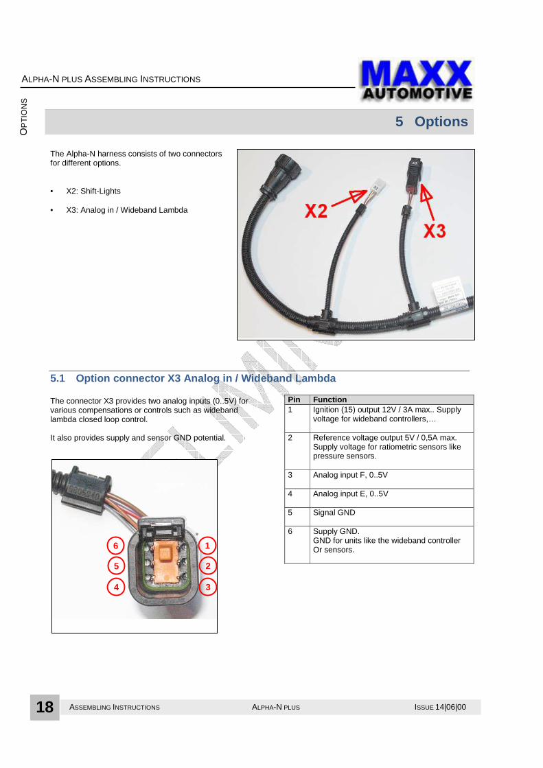
5 Options The Alpha-N harness consists of two connectors for different options. • X2: Shift-Lights • X3: Analog in / Wideband Lambda
5.1 Option connector X3 Analog in / Wideband Lambda The connector X3 provides two analog inputs (0..5V) for various compensations or controls such as wideband lambda closed loop control. It also provides supply and sensor GND potential.
Pin Function 1 Ignition (15) output 12V / 3A max.. Supply
voltage for wideband controllers,…
2 Reference voltage output 5V / 0,5A max. Supply voltage for ratiometric sensors like pressure sensors.
3 Analog input F, 0..5V
4 Analog input E, 0..5V
5 Signal GND
6 Supply GND. GND for units like the wideband controller Or sensors.
1
2
3
6
5
4

ISSUE 14|06|00 ALPHA-N PLUS ASSEMBLING INSTRUCTIONS 19
OP
TIO
NS
ALPHA-N PLUS ASSEMBLING INSTRUCTIONS
5.1.1 Wideband-lambda WBO2 The connector X3 provides everything to connect a WBO2 (wideband lambda) kit. The Alpha-N plus has a function called “closed loop wideband lambda control”. Using a wide band lamda controller (WBO2 kit) the Alpha-N controller supports Mapping and controls fueling while normal run based on an AFR table. We offer such a WBO2 kit which can simply plugged into X3. The user need to run the sensor cable to the sensor. A display is optional.

ASSEMBLING INSTRUCTIONS ALPHA-N PLUS ISSUE 14|06|00 20
ALPHA-N PLUS ASSEMBLING INSTRUCTIONS
OP
TIO
NS
5.2 Option connector X2 Shift Lights Shift Lights is an additional option of the Alpha-N plus controller to indicate adjust- able rpm limits, wbo2 faults or narrow band lambda tendencies. . Example of a Shift Light module... …or single parts
ISSUE 14|06|00 ALPHA-N PLUS ASSEMBLING INSTRUCTIONS 21
GE
NE
RA
L W
IRIN
G D
IAG
RA
M
ALPHA-N PLUS ASSEMBLING INSTRUCTIONS
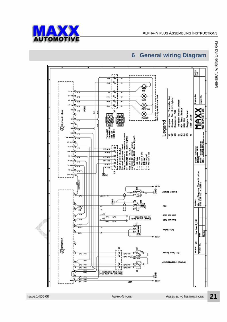
6 General wiring Diagram

ASSEMBLING INSTRUCTIONS ALPHA-N PLUS ISSUE 14|06|00 22
ALPHA-N PLUS ASSEMBLING INSTRUCTIONS
AP
PE
ND
IX
7 Appendix
7.1 Pin- tables Alpha-N kits can be ordered for different engines or different variants. The main harness of each kit has a sticker which tells the version/variant of the kit setup. The actual version is V2.00.
7.1.1 Pin- table of variant up to V1.07
Mot
roni
c p
in
wire
c
olor
Alp
ha-N
p
in Description
2
brown/ blue
2-L
The original wire does NOT need to be tied together with the new wire from the Al-pha-N harness and can be put aside the engine harness outside the motronic con-nector.
3
brown/ black
3-M
The original wire does NOT need to be tied together with the new wire from the Al-pha-N harness and can be put aside the engine harness outside the motronic con-nector.
6
brown/ orange ----------- gray/ green
6-U
Crimp both together. Set into terminal 6.
7
gray/ yellow
7-D G
Remove the original wire from terminal 7 and crimp it together with the POT-G wire of the Alpha-N harness. Isolate the splice with shrink tube and put it aside the engine harness outside the motronic connector. Crimp a pin onto the 7-D wire of the Alpha-N harness and set it into terminal 7 of the motronic connector.
8
black
8-K
Crimp both together. Set into terminal 8.
9
gray/ white
9-N
Crimp both together. Set into terminal 9.
18
blue/ red
18-A
Crimp both together. Set into terminal 18.
24
black
24-E
Crimp both together. Set into terminal 24.
33
white/ yellow
33-J
Crimp both together. Set into terminal 33.

ISSUE 14|06|00 ALPHA-N PLUS ASSEMBLING INSTRUCTIONS 23
AP
PE
ND
IX
ALPHA-N PLUS ASSEMBLING INSTRUCTIONS
7.1.2 Pin- table of variant from V2.00
Mot
roni
c p
in
wire
c
olor
Alp
ha-N
p
in
Description
2
brown/ blue + white
S-B13
Pull out the original motronic pin and lay the wire back, out of the motronic con-nector. Connect it to the S-B13 (white) wire from the Alpha-N harness. Use shrink tubing to isolate.
2
brown/ blue
2-L
Crimp a (small) pin onto the wire 2-L of the Alpha-N harness and insert the wire into terminal 2 of the motronic connector.
3
brown/ black
G-B12
Pull out the original motronic pin and lay the wire back, out of the motronic con-nector. Connect it to the G-B12 (brown/black) wire from the Alpha-N harness. Use shrink tubing to isolate.
3
brown/ black
3-M
Crimp a (small) pin onto the wire 3-M of the Alpha-N harness and insert the wire into terminal 3 of the motronic connector.
6
brown/ orange ----------- gray/ green
6-U
Crimp both together. Set into terminal 6.
7
gray/ yellow
7-D
Remove the original wire from terminal 7 and crimp it together with the POT-G wire of the Alpha-N harness. Isolate the splice with shrink tube and put it aside the engine harness outside the motronic connector. Crimp a pin onto the 7-D wire of the Alpha-N harness and set it into terminal 7 of the motronic connector.
8
black
8-K
Crimp both together. Set into terminal 8.
9
gray/ white
9-N
Crimp both together. Set into terminal 9.
18
blue/ red
18-A
Crimp both together. Set into terminal 18.
24
black
24-E
Crimp both together. Set into terminal 24. OPTIONAL!
33
white/ yellow
33-J
Crimp both together. Set into terminal 33.

ASSEMBLING INSTRUCTIONS ALPHA-N PLUS ISSUE 14|06|00 24
ALPHA-N PLUS ASSEMBLING INSTRUCTIONS
NO
TE
S
8 Notes
Note: This documentation falls under the law of Copyright. Duplication or transmission to others is not authorized, except with explicit permission of MAXX-automotive.
ALPHA-N PLUS ASSEMBLING INSTRUCTIONS
AP
PE
ND
IX
ISSUE 14|06|00 ALPHA-N PLUS ASSEMBLING INSTRUCTIONS 25
MAXX-automotive GmbH Hauptstrasse 49-51 55471 Tiefenbach Germany Phone: +49 6761 9647 94 Fax: +49 6761 9647 99
Email: [email protected]
Web: http://www.maxx-automotive.com DocName: ANplusInstall_BMW_E30_S14_140600en.doc