ansi n13.1 stack sampling system design...
TRANSCRIPT

ANSI N13.1Stack Sampling System
Design Comparison2014 RETS/REMP Workshop
Brian AsamotoHI-Q Environmental Products Company, Inc.
June 23-26, 2014
Nuclear Facility Licensing Requirements
• 10CFR50 – Domestic Licensing of Productionand Utilization Facilities
• Exception to 10CFR50 Applies to USGovernment Production or Utilization Facilities
PROPRIETARY INFORMATION
Air Emissions vs. Effluent ReleaseRequirements
• 10CFR50 – Commercial Nuclear Power Plant Licensing Standard
• 40CFR61 – Hazardous Air Pollution Standard
• ANSI N13.1 - Sampling and Monitoring Releases of AirborneRadioactive Substances from Stacks and Ducts
– ANSI N13.1-1999/2011 applies to government DOD/DOEfacilities
– The NRC has not required operating commercial nuclear powerplants to upgrade to 1999/2011. New construction may berequired to comply with the 1999/2011 version.
PROPRIETARY INFORMATION
Comparison 1969 vs. 1999• 1969 standard defined method of meeting
standard– Defines sampling location
– Requires specific number of sample nozzles
– Defines how to obtain samples representative of theduct particulate distribution
– Little guidance on calculating sample transport systemparticulate deposition
– Recommends verification of fully developed flow andcomplete mixing at sample location
PROPRIETARY INFORMATION
Comparison 1969 vs. 1999• 1999 standard defined performance criteria for
meeting standard– Defines characteristics of the sampling location
• Velocity Profile
• Angle of Velocity Vector
• Tracer Gas Concentration Profile
• Maximum and Minimum Tracer Gas Concentration
• Aerosol Particle Concentration Profile
• Scale model testing can be used in lieu of in-situtesting
PROPRIETARY INFORMATION

Comparison 1969 vs. 1999• 1999 standard provided recommendation for
particle transport efficiency• 1999 standard discourages the use of isokinetic
sampling arrays– Constant cross-section sample nozzles have
significant loss of particles
– Large number of small diameter nozzles increases theparticle losses in the sampling arrays
• 1999 standard suggests the use of a single pointprobe at a representative sample location
PROPRIETARY INFORMATION
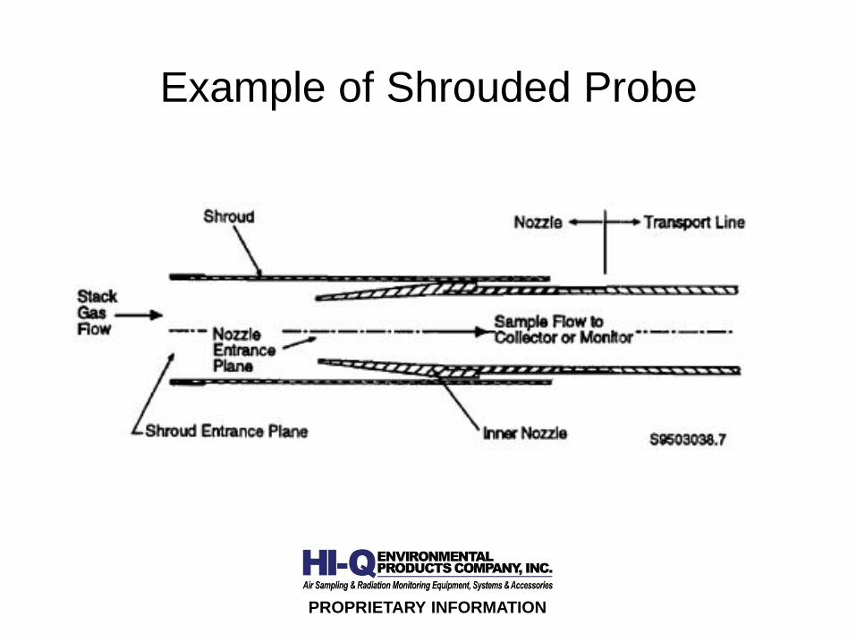
Example of Shrouded Probe
PROPRIETARY INFORMATION
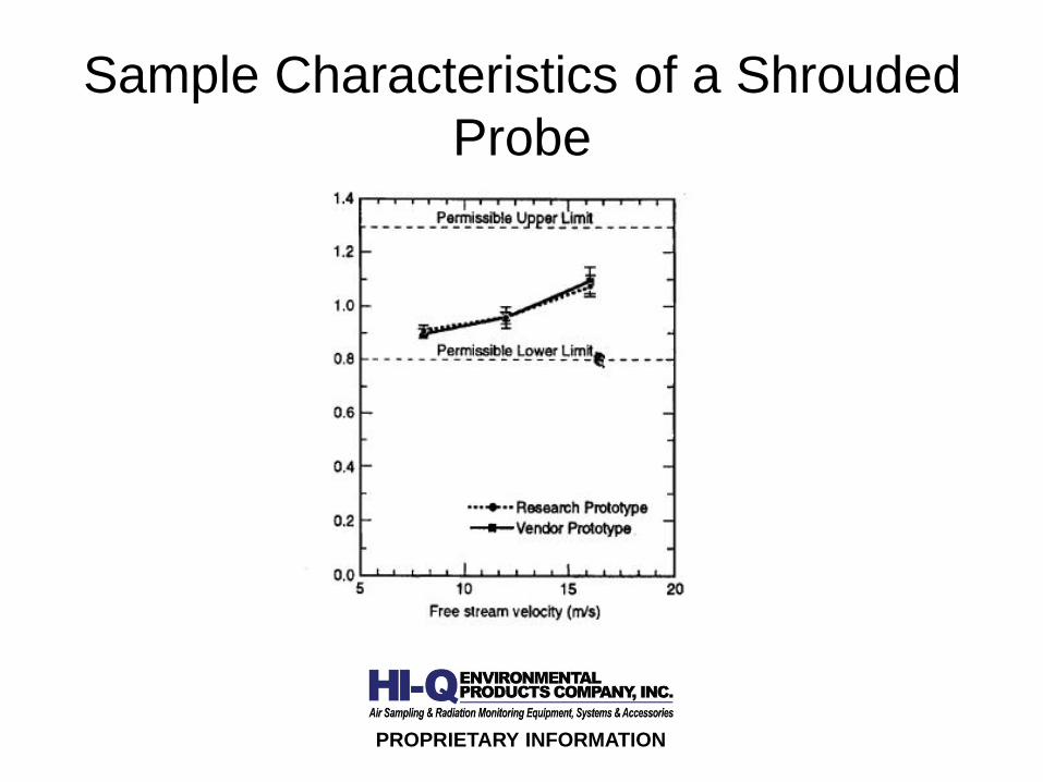
Sample Characteristics of a ShroudedProbe
PROPRIETARY INFORMATION
Isokinetic Sampling Array vs.Shrouded Probe
• Constant cross-section isokinetic nozzle hassignificant wall losses
• Validation testing of isokinetic sampling arraysare recommended
• Shrouded probe has an aerosol transmissionratio within the range of 0.80 to 1.30 ductoperating flow rate
PROPRIETARY INFORMATION
Isokinetic Sampling Array vs.Shrouded Probe
• Shrouded probes perform satisfactorily forvariations in stack conditions:– Velocity– Flow rate– Free stream turbulence– Angle between the free stream and nozzle entrance
• Both require stack sample location testing
PROPRIETARY INFORMATION

Stack/Duct Design Considerations
• Stack/duct design has critical affect on samplerepresentativeness
• Locating representative sample extraction planeis not always intuitive
• All current acceptance criteria may not be easilymet at the selected sample extraction plane
• Gas mixing techniques may improverepresentativeness
PROPRIETARY INFORMATION

Examples of Tested Stack/duct Designs
• Department of Energy Facility Exhaust Stack• Columbia Generating Station Elevated Vent• AP1000 Plant Vent• AP1000 Control Room Ventilation Duct
PROPRIETARY INFORMATION

Test Methodology
• Velocity profile test• Swirl angle test• Tracer gas concentration profile test• Maximum and minimum tracer gas concentration
evaluation• Aerosol particle concentration profile test
PROPRIETARY INFORMATION

DOE Facility Qualified Sample Location
PROPRIETARY INFORMATION
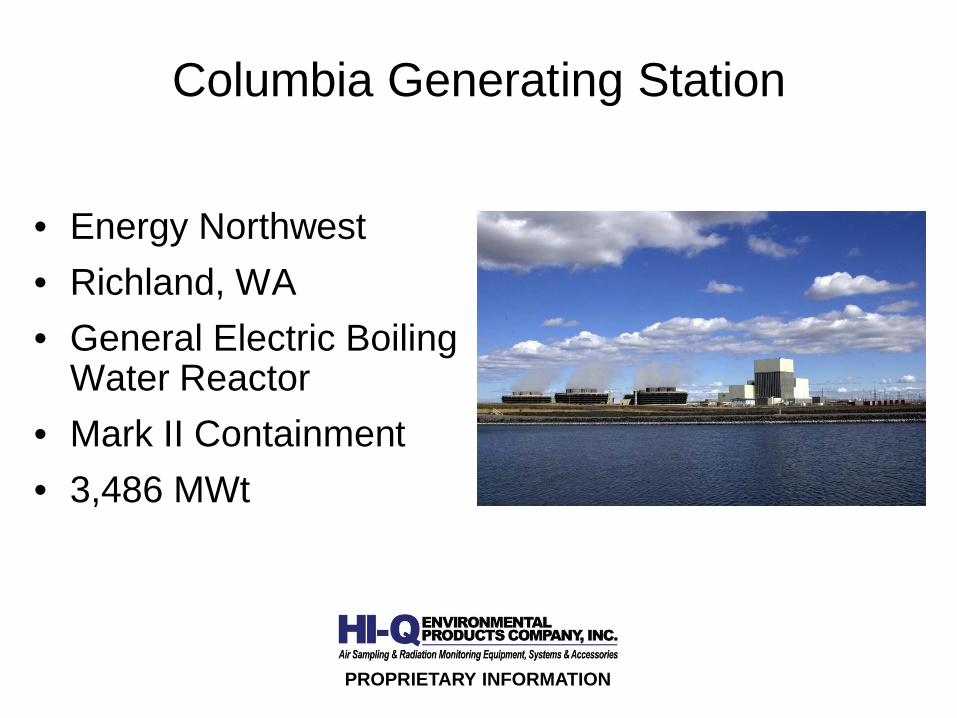
Columbia Generating Station
• Energy Northwest• Richland, WA• General Electric Boiling
Water Reactor• Mark II Containment• 3,486 MWt
PROPRIETARY INFORMATION

Key Elements of the ElevatedVent Stack Design
• Normal operation – Reactor Building HVAC Duct• Post-accident operation – Standby Gas
Treatment (SGTS) Duct• Existing stack sampling system
– Flow straightener section– Self-averaging pitot tube array– Correction of flow rate to standard conditions– Multipoint isokinetic sampling array
• SGTS Air Exhausts Through Internal Duct
PROPRIETARY INFORMATION

Stack Sampling System Design Basis• ANSI N13.1-1969 used for original design criteria• Normal and post-accident flow rates will be used
for ANSI N13.1-1999 test criteria• Test was conducted on scale model of the stack
and inlet ducts• Testing was conducted with and without flow
straightener• Replace multi-point sample array with shrouded
probe• Eliminate flow straightener
PROPRIETARY INFORMATION
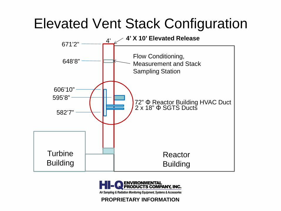
Elevated Vent Stack Configuration
PROPRIETARY INFORMATION
72” Reactor Building HVAC Duct
671’2”4’ X 10’ Elevated Release
2 x 18” SGTS Ducts
ReactorBuilding
TurbineBuilding
4’
582’7”
648’8”Flow Conditioning,Measurement and StackSampling Station
595’8”606’10”

SGTS Duct Configuration
PROPRIETARY INFORMATION
72” Reactor BuildingHVAC Duct
606’10”20” X 20” StackOpen at both ends
2 x 18” SGTS Ducts
582’7”

Scale Model Configuration
PROPRIETARY INFORMATION

Scale Model
PROPRIETARY INFORMATION

SGTS Stack
PROPRIETARY INFORMATION

Test Performance
• Minimum Reactor Building HVAC Duct flow rate• Maximum Reactor Building HVAC Duct flow rate• Minimum SGTS Duct flow rate (Two ducts)• Maximum SGTS Duct flow rate (Two ducts)• Tests repeated without flow straightener
PROPRIETARY INFORMATION
Test Results
• Test results for normal operation• Test results for post-accident operation• Test results without flow straightener• Particle uniformity test was not repeated for post-
accident operation without flow straightener
PROPRIETARY INFORMATION

Normal Operation Velocity Profile
PROPRIETARY INFORMATION
With Flow Straightener Without Flow Straightener
COV=9.3% COV=9.1%fpm = feet per minute
x,1
x,2
x,3
x,4
150016001700180019002000210022002300
1,y 2,y 3,y 4,y
fpm
Flow Direction x,1
x,2
x,3
x,4
160017001800190020002100220023002400
1,y 2,y 3,y 4,y
fpm
Flow Direction

Normal Operation Tracer Gas Uniformity
PROPRIETARY INFORMATION
With Flow Straightener Without Flow Straightener
COV=10.1% COV=8.2%
ppm = parts per million
x,1
x,2
x,3
x,4
0.900.951.001.051.101.151.201.251.30
1,y 2,y 3,y 4,y
ppm
Flow Direction x,1
x,2
x,3
x,4
3.5
3.7
3.9
4.1
4.3
4.5
4.7
4.9
1,y 2,y 3,y 4,y
ppm
Flow Direction

Normal Operation Particle Uniformity
PROPRIETARY INFORMATION
With Flow Straightener Without Flow Straightener
COV=11.4% COV=5.4%cpm = counts per minute
x,1
x,2
x,3
x,4
260280300320340360380400420
1,y 2,y 3,y 4,y
cpm
Flow Direction x,1
x,2
x,3
x,4
300
310
320
330
340
350
360
370
1,y 2,y 3,y 4,y
cpm
Flow Direction

Post-accident OperationVelocity Profile
PROPRIETARY INFORMATION
With Flow Straightener Without Flow Straightener
COV=19.1% COV=38.3%fpm = feet per minute
x,1
x,2
x,3
x,4
0
20
40
60
80
100
1,y 2,y 3,y 4,y
fpm
Flow Direction x,1
x,2
x,3
x,4
40
60
80
100
120
140
1,y 2,y 3,y 4,y
fpm
Flow Direction

Post-accident OperationTracer Gas Uniformity
PROPRIETARY INFORMATION
With Flow Straightener Without Flow Straightener
COV=11.5% COV=6.4%ppm = parts per million
x,1
x,2
x,3
x,4
0.6
0.7
0.8
0.9
1.0
1.1
1,y 2,y 3,y 4,y
ppm
Flow Direction x,1
x,2
x,3
x,4
1.0
1.1
1.2
1.3
1.4
1,y 2,y 3,y 4,y
ppm
Flow Direction

Post-accident OperationParticle Uniformity
PROPRIETARY INFORMATION
With Flow Straightener
COV=4.7%
x,1
x,2
x,3
x,4
1.001.051.101.151.201.251.301.351.40
1,y 2,y 3,y 4,y
cpm
Flow Direction
cpm = counts per minute
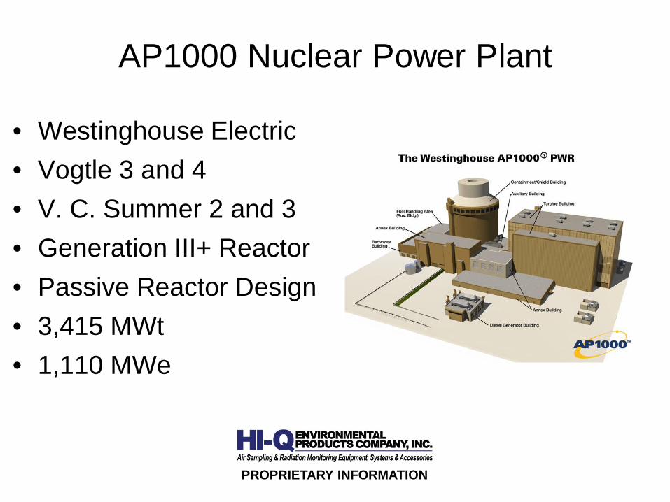
AP1000 Nuclear Power Plant
• Westinghouse Electric• Vogtle 3 and 4• V. C. Summer 2 and 3• Generation III+ Reactor• Passive Reactor Design• 3,415 MWt• 1,110 MWe
PROPRIETARY INFORMATION

Plant Vent Design• Normal Operation
– Aux/Annex Building Exhaust (2 sources)– Fuel Handling Area Exhaust (2 sources)– Containment Air Filtration Exhaust– Health Physics & Hot Machine Shop Exhaust– Radwaste Building Exhaust
• Post-accident Operation – Containment AirFiltration Exhaust
• Stack Sampling System– Normal operation sampling by shrouded probe– Post-accident operation sampling by single isokinetic
nozzle
PROPRIETARY INFORMATION

Plant Vent Scale Model Configuration
PROPRIETARY INFORMATION

Scale Model Design
• Model scale is 1:5• Plant vent and four inlet ducts were modeled• Five fans controlled the air flow through the four
inlet ducts• Correct flow rates required balancing each fan’s
output
PROPRIETARY INFORMATION
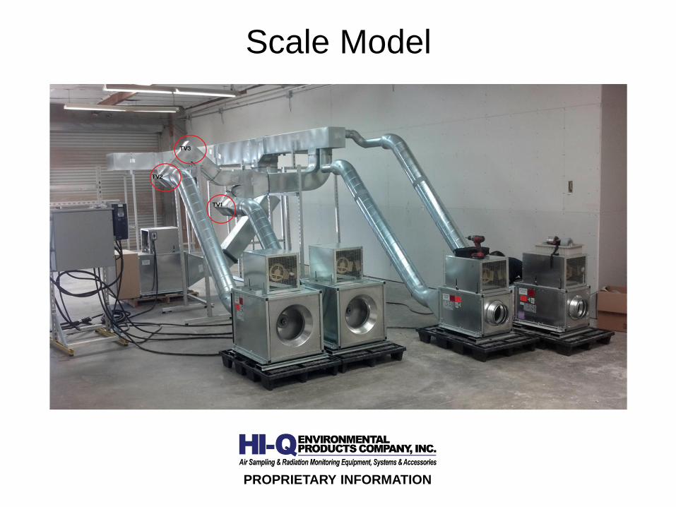
Scale Model
PROPRIETARY INFORMATION
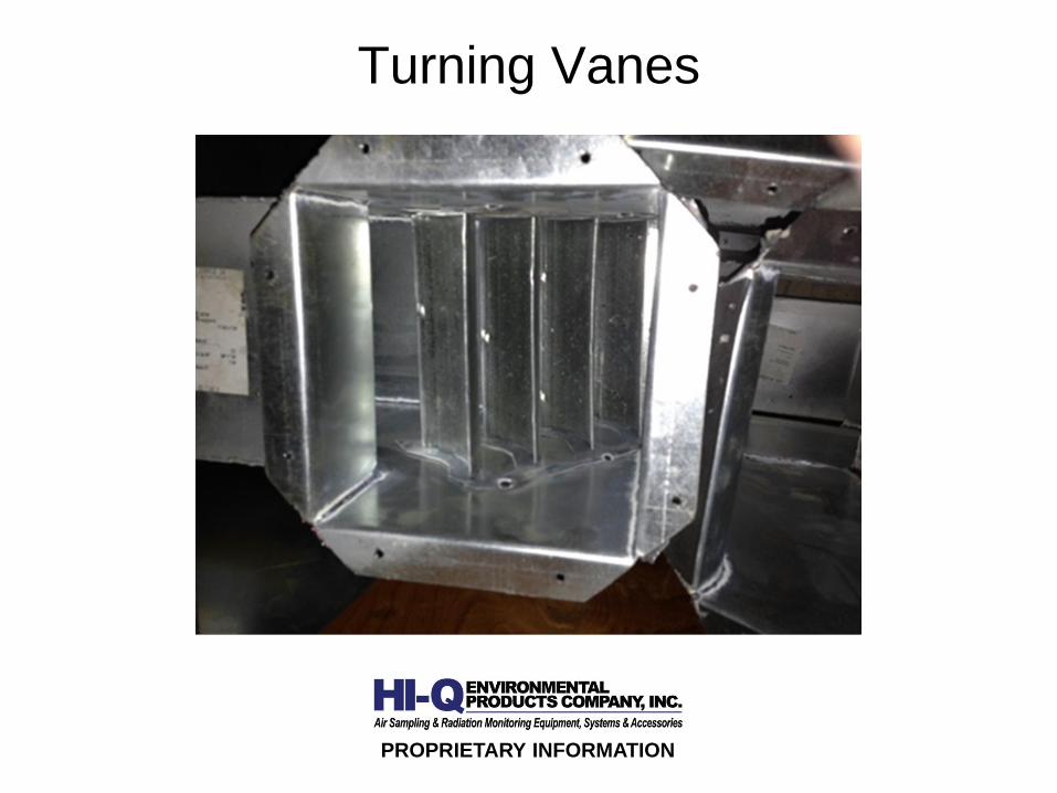
Turning Vanes
PROPRIETARY INFORMATION

Test Results
• Velocity Profile COV – Pass• Swirl Angle - Pass• Tracer Gas Concentration COV – Pass• Maximum Variation from Tracer Gas Mean
Concentration – Pass• Aerosol Particle Concentration Profile COV - Pass
PROPRIETARY INFORMATION

Control Room Ventilation DuctScale Model Configuration
PROPRIETARY INFORMATION

Scale Model Design
• Model scale is 1:2.33• Tracer gas and aerosol particle injected at fan
outlet• Turning Vanes• Balancing Damper• Gas blender was required to pass velocity profile
COV
PROPRIETARY INFORMATION

Scale Model
PROPRIETARY INFORMATION

Balancing Damper
PROPRIETARY INFORMATION
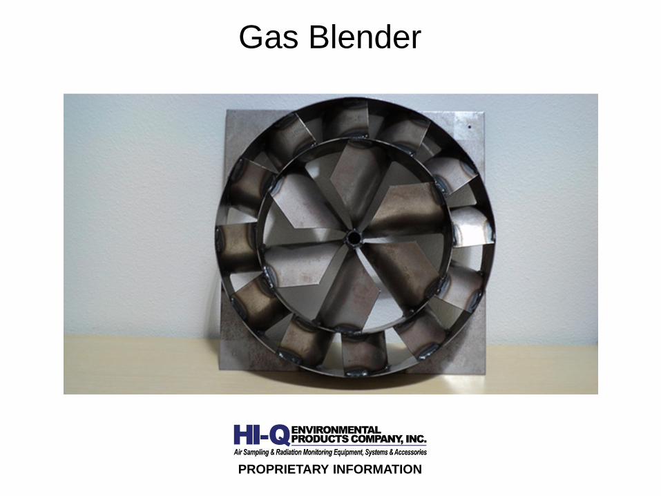
Gas Blender
PROPRIETARY INFORMATION

Test Results
PROPRIETARY INFORMATION
• Velocity Profile COV – Fail (without gas blender)• Swirl Angle - Pass• Tracer Gas Concentration COV – Pass• Maximum Variation from Tracer Gas Mean
Concentration – Pass• Aerosol Particle Concentration Profile COV - Pass
Conclusions
• Vent stacks should be designed for mixing andflow uniformity at sampling location
• Longer straight run improves mixing and flowunifority
• High probability for successful test results withnon-ideal stack/duct designs
PROPRIETARY INFORMATION
Conclusions
• Mixing and flow uniformity problems havesolutions
• Reasonable representativeness possible withANSI N13.1-1969 design
• Compliance with ANSI N13.1-1999 enhances therepresentativeness of the particulate sample
PROPRIETARY INFORMATION