ansi/gbi 01-2010 green building assessment protocol for ... · ansi/gbi 01-2010 standard document...
TRANSCRIPT

. Page i of 96
ANSI/GBI 01-2010
Green Building Assessment Protocol for Commercial Buildings
An American National Standard
April 1, 2010
NOTICE: © 2010 Green Building Initiative, Inc. All rights reserved. Any copying or redistribution of this document or any of its contents without GBI’s prior written consent is strictly prohibited. Your possession and use of this document and its contents are subject to the terms and conditions of an End User License Agreement with Green Building Initiative, Inc.

ii © 2009 Green Building Initiative, Inc. All rights reserved.
ANSI/GBI 01-2010 Green Building Assessment Protocol for Commercial Buildings FOREWORD Note that the information contained in this Foreword is not part of this Standard. It does not contain requirements necessary for conformance to the Standard. It has not been processed in accordance with American National Standards Institute’s (ANSI) requirements for an ANS and may contain material that has not been subjected to public review or a consensus process. In addition, it does not contain requirements necessary for conformance to the standard. About the Green Building Initiative The Green Building Initiative (GBI) is a not-for-profit organization that in 2005 became accredited as a standards developer by ANSI. GBI owns the U.S. license for Green Globes®—a green commercial building rating system that combines education with environmental assessments in fully interactive online tools for new and existing buildings. Green Globes® is a unique green management tool that is flexible, user-friendly and affordable, while still offering a rigorous and credible approach to assessing green building design, construction, operations and maintenance processes. Who Should Use This Standard Building owners, architects, design teams, developers, contractors and various levels of government can apply this Standard to a broad range of commercial building types—such as office, multi-family, health care, schools, universities, labs, industrial, and retail. ANSI/GBI 01-2010 includes prescribed levels of achievement that government agencies, or other entities wishing to establish specific criteria may consider when creating their own specific standards. It does not apply to single-family homes, two-family homes and townhouses that are three stories or less in height, as such structures are covered in the ANSI/ICC 700-2008 developed by the National Association of Home Builders (www.nahb.com) and the International Codes Council. Flexibility and Regionality Flexibility is built into this Standard allowing users to consider the whole building life cycle, regional climatic issues, and local laws and ordinances. Users are encouraged to strive for the highest number of assessed points possible for the building type, in keeping with the owners’ goals and objectives and while considering the potential for future uses of the building and/or deconstruction approaches. The Green Building Initiative, Green Globes® & ANSI This standard document represents a further development of the current rating system incorporated into the Green Globes® online tools. At the current time this standard protocol is not contained within the Green Globes online tools or assessment/certification systems. The assessment protocol—or rating system—contained within the ANSI/GBI 01-2010 standard document applies to new commercial buildings and major renovations. The standard includes criteria related to planning for subsequent operations and maintenance. About the ANSI/GBI 01-2010 Standard The ANSI/GBI 01-2010 Green Building Assessment Protocol for Commercial Buildings (the “Standard”) provides a method of assessing commercial buildings in relation to commonly valued environmental and efficiency outcomes. The Standard is an assessment tool and does not purport to instruct users on the appropriate or applicable design, construction, operation, maintenance, standards, laws, codes or regulations with respect to any building. The use of the Standard in this document does not establish, expressly or implicitly, the appropriate standard of care of licensed design or other professionals nor the appropriate duties and responsibilities of owners, design, construction, operations or maintenance personnel. The use of this standard document alone does not constitute assessment or certification of any building. GBI does not guarantee or warrant any particular outcome or certification as a result of any individual use of the Standard Building Assessment & Certification utilizing the ANSI/GBI 01-2010 Standard GBI is offering a limited number of pilot program building assessments and certifications utilizing this standard assessment protocol. Interested parties that have new construction or major renovation projects that would like to apply to the GBI for inclusion in the pilot program, and if approved, have their project assessed and/or certified against the ANSI/GBI 01-2010 standard can send their inquiry to [email protected] or make an application online (after May 1,2010) at www.thegbi Start of ANSI/GBI 01-2010 This ends the part of the document that is not included in this American National Standard.

iii © 2009 Green Building Initiative, Inc. All rights reserved.
Reference documents cited within the Standard are mandatory unless they are clearly identified as being informational references. Referenced documents are only to be applied within the context for which they are cited.
TABLE OF CONTENTS
FOREWORD....................................................................................................................................................... ii 1. PURPOSE ...................................................................................................................................................... 1 2. SCOPE ........................................................................................................................................................... 1 3. ACHIEVEMENT LEVELS, MINIMUMS, NON-APPLICABLES AND THIRD PARTY ASSESSMENTS ................................................................................................................................................... 1 4. ASSESSMENT OF COMPLIANCE ............................................................................................................. 2 5. DEFINITIONS, ABBREVIATIONS, AND ACRONYMS ........................................................................... 3 6. PROJECT MANAGEMENT FOR GREEN DESIGN AND DELIVERY COORDINATION (GDDC) ....... 11 7. SITE ............................................................................................................................................................. 16 8. ENERGY ..................................................................................................................................................... 23 9. WATER ....................................................................................................................................................... 42 10. RESOURCES/MATERIALS ...................................................................................................................... 49 11. EMISSIONS ................................................................................................................................................ 63 12. INDOOR ENVIRONMENT ........................................................................................................................ 66 13. REFERENCES AND GUIDELINES .......................................................................................................... 79 14. APPENDICES ............................................................................................................................................. 85 Appendix A - GDDC Progress Meeting Agendas for Design ............................................................................. 85 Appendix B - GDDC Progress Meeting Agendas for Construction ................................................................... 86 Appendix C - Carbon Dioxide (CO2) Monitoring Protocol ............................................................................... 86 Appendix D - Carbon Monoxide (CO) Monitoring Protocol ............................................................................. 86 Appendix E - Chemical Management and Minimization Policy........................................................................ 86 Appendix F - Energy Measurement and Verification Protocol/ Energy Metering Reporting Plan .................. 87 Appendix G - Low-impact Site and Green Building Exterior Management Plan ............................................. 87 Appendix H – Integrated Pest Management Plan ............................................................................................... 87 Appendix I - Site Maintenance Contract ........................................................................................................... 87 Appendix J - Sustainable Purchasing Policy for Cleaning Products and Materials ......................................... 88 Appendix K - Waste Minimization Plan ............................................................................................................ 88 Appendix L - Water Efficiency Measurement and Verification Plan ............................................................... 88 Appendix M - Green Globes® Water Consumption Calculator, Version 1.3 ................................................... 88 Appendix N - Green Globes® LCA Credit Calculator for Building Assemblies, Version 1.9.43 ...................... 89 Appendix O - Resource Conservation through Design ...................................................................................... 92

1 © 2010 Green Building Initiative, Inc. All rights reserved.
ANSI/GBI 01-2010 Green Building Assessment Protocol for Commercial Buildings
1. PURPOSE This Standard provides a method of assessing commercial buildings in relation to commonly valued environmental and related efficiency outcomes. 2. SCOPE This Standard applies to a broad range of commercial building types, including offices, multi-family, health care, schools, universities, labs, industrial, retail, etc., as well as to major renovations. The Standard does not apply to single-family homes, two-family homes and townhouses that are three stories or less in height. The Standard includes a point-based assessment or rating system that allows users to identify solutions that earn points for outcomes likely to achieve levels of performance commonly valued as having desirable environmental and related efficiency outcomes. The assessment criteria and rating system within the Standard apply to new commercial buildings and major renovations, including criteria related to planning for subsequent operations and maintenance. The seven areas of assessment within the Standard include Project Management, Site, Energy, Water, Resources/Materials, Emissions, and Indoor Environment. This Standard shall not be used to circumvent any code, health, safety, security, or environmental requirements. It is the sole responsibility of the user of this Standard to establish appropriate safety and health practices, to comply with required building codes, and to assess the applicability of criteria based on other possible regulatory limitations prior to use. 3. ACHIEVEMENT LEVELS, MINIMUMS, NON-APPLICABLES AND THIRD
PARTY ASSESSMENTS 3.1 Achievement Levels Levels of Achievement 1, 2, 3, and 4 are specified in Table 1 below.
TABLE 1 Levels Percentage of Points Achieved Out
of Applicable Points Description
Level 4 85-100% Reserved for select buildings that serve as national or world leaders through focus on reducing environmental impacts.
Level 3 70-84% Demonstrates leadership in energy and environmentally sensitive buildings and a commitment to continual improvement.
Level 2 55-69% Demonstrates excellent progress in reducing environmental impacts by applying best practices toward energy and environmentally sensitive buildings.
Level 1 35%-54% Demonstrates movement beyond awareness and a commitment to toward good energy and environmentally sensitive buildings.

2 © 2010 Green Building Initiative, Inc. All rights reserved.
3.2 Minimum Achievement Requirements To achieve compliance in any of the four Levels, buildings must: 1. Attain a minimum of 35% of applicable points out of the 1000 possible points available; and 2. Attain a minimum percentage of points in each environmental assessment area as denoted in Table 2. Where calculations are used to determine points achieved, round to the nearest whole number.
TABLE 2 Environmental Assessment Area
Total Points Available Minimum Percentage of Points Required For Compliance at Each of the Four Levels
Project Management 100 50% Site 120 24% (0 for major renovations) Energy 300 Performance Path A: 50%
Prescriptive Path B: 33% Water** 130 26% Resources/Materials 145 29% Emissions 45 9% Indoor Environment 160 32% Total 1000 (less non-applicable
points)
**The Water Assessment Area has a unique method for calculating final point allocations. Please refer to section 9.1 for further information. 3.3 Non-applicable Criteria. Each environmental assessment area contains certain criteria that a design and delivery team may deem to be “non-applicable” to the building. Selecting “non-applicable” may be appropriate in the following circumstances as denoted in Table 3:
TABLE 3 Reasons for Use of Non-applicable Criteria 1 If a criterion does not apply to the building type (e.g. if there are no oil fired burners on site; questions
related to oil fired burners would be designated non-applicable). 2 If a code or regulation overrides, conflicts with, or otherwise prevents compliance with a criterion. 3 If a criterion conflicts with best practices based on regional climatic differences. Questions without a non-applicable option should be answered as appropriate for the building. 4. ASSESSMENT OF COMPLIANCE Assessment of compliance with a specific Level of Achievement (Table 1) can be established through third-party review of appropriate written plans, working drawings, specifications, site plans, energy modeling, life cycle assessment results, commissioning reports, construction documents and/or other data or documents that demonstrate conformance. Items from the “Suggested Documentation” list at the end of each area of compliance in this Standard are typical documents that providers of third -party assessment will use prior to or in conjunction with a post-construction site visit and walk-through to assess compliance, although other documentation may be requested or substituted prior to or during the on-site visit. Informational reference(s):
• The Green Building Initiative’s Third-Party Rating/Certification for Green Globes®

3 © 2010 Green Building Initiative, Inc. All rights reserved.
5. DEFINITIONS, ABBREVIATIONS, AND ACRONYMS 5.1 Definitions Note: Italicized words found throughout this Standard indicate that a definition for the term can be found in the Definitions section. Definitions not found in this section may be found in referenced standards contained in this Standard, and the user shall adhere to the meanings as defined in those standards. Other terms not defined in this section nor in referenced standards contained in this standard shall have their ordinarily accepted meanings within the context in which they are used. Ordinarily accepted meanings are based upon American Standard English language usage as documented in a comprehensive dictionary. Where definitions in this Standard differ from those in a reference standard or any other source, definitions found in this standard shall be used. 25-year, 24-hour storm event: means the maximum 24-hour precipitation event with a probable recurrence interval of once in 25 years, as defined by the National Weather Service. acoustically separated area: an enclosed space that, to function properly, requires separation from other adjacent spaces by wall, floor, and ceiling assemblies that have an STC rating adequate to allow clear, intelligible communication between sender and receiver within the space (e.g.meeting rooms, auditoria, theaters, concert venues, cinemas, lecture halls, libraries, classrooms, conference rooms, counseling offices, private offices, private rooms in health care facilities, sleeping rooms, etc.). air economizer: system found on HVAC air handling systems that takes advantage of favorable weather conditions to reduce mechanical cooling by introducing cooler outdoor air into a building. assemblies: building systems categorized as exterior walls, internal partitions, windows, interim floors, roofs, beams and columns. basis of design: a document that records the concepts, calculations, decisions, and product selections used to meet the owner’s project requirements and to satisfy applicable regulatory requirements, standards, and guidelines. The document includes both narrative descriptions and lists of individual items that support the design process. baseline equivalent emission rate (BER): the baseline building emission rate (BER) represents the mass carbon dioxide equivalent emitted for the average U.S. commercial building in the proposed building’s location when using data from the U.S. Department of Energy’s Energy Information Administration’s (EIA) “Commercial Building Energy Consumption Survey (CBECS).” The BER is expressed as the mass of CO2e emitted per year per unit area of the total useful floor area of a building – kg/m2/yr (lb/ft2/yr). bio-based product: commercial or industrial product using at least 50% (by weight), biologically-generated substances, including but not limited to cellulosic materials (e.g. wood, straw, natural fibers) and products derived from crops (e.g. soy-based, corn-based). brownfield: real property, the expansion, redevelopment, or reuse of which may be complicated by the presence or potential presence of a hazardous substance, pollutant, or contaminant (Some legal exclusions and additions may apply). building envelope: the element of a building that separates the conditioned interior space from the exterior, such as walls, roofs, floors, slabs, foundations, doors, and fenestration. C-factor: the amount in British Thermal Units (Btu) that flows each hour though 1 ft² of surface area of material when there is a 1° temperature difference between the inside and outside air Btu/hr-ft²-F. carbon dioxide equivalent (CO2e): a measure used to compare the impact of various greenhouse gases based on their global warming potential (GWP). CO2e approximates the time-integrated warming effect of a unit of a given

4 © 2010 Green Building Initiative, Inc. All rights reserved.
greenhouse gas, relative to that of carbon dioxide (CO2). GWP is an index for estimating the relative global warming contribution of atmospheric emissions of a unit mass of a particular greenhouse gas compared to emission of a unit mass of CO2. The following GWP values are used based on a 100-year time horizon: 1 for CO2, 23 for methane (CH4), and 294 for nitrous oxide (N2O). (See global warming potential) charrette: a collaborative session in which a project team creates a solution to a design or project problem. The structure may vary, depending on the complexity of the problem or desired outcome and the individuals working in the group. Charrettes can take place over multiple sessions in which the group divides into sub-groups. Each sub-group then presents its work to the full group as material for future dialogue. Charrettes can serve as a way of quickly generating solutions while integrating the aptitudes and interests of a diverse group of people. CAS number: assignment by the Chemical Abstracts Service (CAS), a division of the American Chemical Society, which assigns numbers to chemicals to allow for database searches. Most molecule databases allow searching by CAS number. climate zone: see Section 5.1.4 of ANSI/ASHRAE/IESNA Standard 90.1-2007, or Section 301 of the 2009 International Energy Conservation Code (IECC). commercial zone: a developed area that includes facilities for the sale of commodities or performance of services, including but not limited to fire, rescue and police stations, post office, solid waste dumpsters and transfer stations, road maintenance yards, community wells/storage tanks and treatment, day care centers, schools, parks, playgrounds and play fields, community assembly, recreation centers, administrative offices, public and private non-profit clubs/meeting halls, automotive sales and service, laundries, food markets, offices for for-profit businesses, private recreation clubs, household goods and office supplies, restaurants, galleries, pharmacies, furniture and appliances, small equipment, theatres, bakeries, salons, etc. construction documents: all of the written and graphic documents (including BIM, CAD, and other electronic files) prepared or assembled by the architect/engineer for communicating the design and administering the project. The term “Construction Documents” also includes the Project Manual that contains the bidding forms and instructions, contract forms and conditions, and specifications, as well as documentation of all modifications made after the construction agreements are signed. construction documents phase: the last stage of the design process. The design and delivery team is focused on finalizing the drawings and specifications for all components and systems of the building producing the Contract Documents. A complete set of Contract Documents provides a comprehensive, fully coordinated set of construction documents and specifications that the contractor uses to obtain necessary permits and construct the project. daylighting: the use of natural light to minimize the need for artificial lighting during the day using strategies such as effective orientation and placement of windows, use of light wells, light shafts or tubes, skylights, clerestory windows, light shelves, reflective surfaces, and shading, and the use of interior glazing to allow light into adjacent spaces. demand controlled ventilation: automatic ventilation control based on occupant demand. design development phase: refines the scope of work previously approved in the schematic design phase. In this phase the project is developed to a level of detail necessary to work out a clear, coordinated description of all aspects of the project. Major elements including equipment, fire protection, mechanical, electrical, structural, telecommunications and plumbing systems are designed and coordinated through enlarged scale drawings, detailed elevations and plans, and design mock-ups as required. direct lighting: lighting provided from a source without reflection from other surfaces, which allows light to travel on a straight path from the light source to the point of interest, such as a ceiling-mounted or suspended luminaires with mostly downward light distribution characteristics.

5 © 2010 Green Building Initiative, Inc. All rights reserved.
district cooling: distributes chilled water or other media to multiple buildings for air conditioning or other uses. The cooling (actually heat rejection) is usually provided from a dedicated cooling plant. district heating: the distribution of heat from one or more sources to multiple buildings. drift eliminator: structure to control water lost from cooling towers as liquid droplets are entrained in the exhaust air. A drift eliminator does not prevent water lost by evaporation. drought tolerant plants: plants that can withstand long periods with little or no water and/or that have relatively low water requirements. effective aperture for vertical fenestration (EAvf): the product of the visible transmittance of the ovrall vertical fenestration product (entire rough opening including glass, sash, and frame) and the vertical fenestration area as a percentage of the gross wall area. Visible transmittance is determined in accordance with ANSI/ASHRAE/IESNA Standard 90.1-2007, Section 5.8.2.6. existing buildings: a building or portion thereof that was previously occupied or approved for occupancy by the authority having jurisdiction. exterior insulation finishing systems (EIFS): a non-load bearing exterior wall finishing system that consists of expanded polystyrene foam insulation panels attached adhesively or mechanically to the substrate, a trowel-applied base coat with fiber glass reinforcing mesh, and a trowel-applied finish coat. exterior vegetated space: means outside the building footprint and paved areas. Applies only to sites where the site is vegetated with plants that are native, adapted to the ecosystem and/or non-invasive. fenestration: all areas (including frames) in the building envelope that transmit light including windows, translucent panels, clerestory windows, skylights, and glass block walls. For doors where the glazed vision area is less than 50% of the door area, the fenestration area is the glazed vision area. For all other doors, the fenestration area is the door area (including frames). fenestration area: total area of the fenestration measured using the rough opening and including glass, sash, and frame. f-factor: the perimeter heat loss factor for slab-on-grade floor, expressed in Btu/hr-ft-oF (W/m-K) furnishings, finishes, and fit-outs: products and materials permanently installed on the interior of a building. This definition includes casework, shelving and cabinets as well as finish materials used on floors, walls and ceilings. This definition does not include moveable furniture such as desks, tables and chairs. green design and delivery coordination (GDDC): a process in which the project team is led by an individual and/or a team of individuals in the setting and ranking of measurable sustainable design and project delivery goals through an integrated process, and which facilitates reporting mechanisms to report to the team and owner on the progress made toward each goal, along with documentation of the process. GDDC coordinator: the individual with primary responsibility for coordinating, facilitating, documenting and reporting on the green design and delivery coordination process. GDDC team: the group of individuals selected or appointed to represent the various disciplines relevant to the project throughout the green design and delivery coordination process. global warming potential (GWP): an index, describing the radiative characteristics of well mixed greenhouse gases, that represents the combined effect of the differing times these gases remain in the atmosphere and their relative effectiveness in absorbing outgoing infrared radiation. This index approximates the time-integrated warming

6 © 2010 Green Building Initiative, Inc. All rights reserved.
effect of a unit mass of a given greenhouse gas in today’s atmosphere, relative to that of carbon dioxide. (See carbon dioxide equivalent) graywater: Untreated waste water that has not come into contact with toilet waste, kitchen sink waste, dishwasher waste or similarly contaminated sources. Graywater includes waste water from bathtubs, showers, and bathroom wash basins, clothes washers and laundry tubs. greenfield: undeveloped lands such as fields, forests, farmland or rangeland. grid displaced electricity: grid displaced electricity comprises all electricity generated in or on the building site by, for example PV panels, wind-power, combined heat and power systems (CHP), or similar systems. impervious area: a hard surface area (e.g., parking lot) that prevents or retards the entry of water into the soil, thus causing water to run off the surface in greater quantities and at an increased rate of flow. indoor environmental quality: refers to the quality of the air and environment inside buildings, based on pollutant concentrations and conditions that can affect the health, comfort and performance of occupants-including temperature, relative humidity, light, sound and other factors. integrated pest management: the use of different techniques to control pests, used singly or in combination, such as selection of pest-resistant plant varieties, regular monitoring for pests, use of pest-resistant materials or use of natural predators of the pest, to control pests, with an emphasis on methods that are least injurious to the environment and most specific to the particular pest. light pollution: any adverse effect of artificial light including sky glow, glare, light trespass, light clutter, decreased visibility at night, and energy waste. low slope roofing: a roofing assembly applied to a roof deck having a slope less than or equal to 7.6 cm/m (3 in/ft). luminaire: a complete lighting unit, consisting of a lamp or lamps together with the components required to distribute the light, position the lamps, and connect the lamps to a power supply (often referred to as a “fixture”). major renovation: has occurred when 50% of the gross area (measured to the exterior footprint) of the building has been renovated. municipally reclaimed water: non-potable water delivered by a municipal authority that meets or as a result of treatment, meets water quality requirements for its intended uses. The level of treatment and quality of the reclaimed water shall be approved by the authorityhaving jurisdiction. net building area: the square footage area of all interior spaces as measured to the predominant interior surface of the outside wall and excluding mechanical, elevator and utility shafts but ignoring protrusions caused by structural elements. non-potable water: water that is not potable water (see potable water). off-site renewable energy: green power or Renewable Energy Certificates (RECs) purchased from a third-party source such as an electrical utility. There is no physical renewable energy system either on site or specifically connected to the building. on-site renewable energy: energy derived from sun, wind, water, Earth's core, and biomass that is captured, stored and used on the building site, using such technologies as wind turbines, photovoltaic solar panels, transpired solar collectors, solar thermal heaters, small-scale hydroelectric power plants, fuel cells, and ground-source heat pumps.

7 © 2010 Green Building Initiative, Inc. All rights reserved.
organic mulch: any material, that used to be living and will decompose, applied to the soil surface for protection or improvement of the area covered such as tree bark, pine needles, grass or hay clippings, leaves, straw, shredded hardwood, etc. orientation: the relation of a building and its associated fenestration and interior surfaces to compass direction and, therefore, to the location of the sun, usually given in terms of angular degrees away from south, (e.g. a wall facing due Southeast has an orientation of 45 degrees east of south). overhang: a horizontal projection for a window or wall. ozone depletion potential (ODP): a number that refers to the amount of ozone depletion caused by a substance. The ODP is the ratio of the impact on ozone of a chemical compared to the impact of a similar mass of CFC-11. Thus, the ODP of CFC-11 is defined to be 1.0. Other CFCs and HCFCs have ODPs that range from 0.01 to 1.0. The halons have ODPs ranging up to 10. Carbon tetrachloride has an ODP of 1.2, and methyl chloroform's ODP is 0.11. HFCs have zero ODP because they do not contain chlorine. Manufacturers publish tables of all ozone depleting substances showing their ODPs, GWPs, and CAS numbers. post-consumer recycled content: proportion of recycled material in a product that is generated by households or by commercial, industrial and institutional facilities in their role as end-users of the product, which can no longer be used for its intended purpose. This includes returns of material from the distribution chain (see recycled material). potable water: water from public drinking water systems or from natural freshwater sources such as lakes, streams, and aquifers where water from such natural sources would or could meet federal drinking water standards. pre-consumer recycled content: proportion of recycled material in a product that is diverted from the waste stream during the manufacturing process. Content not considered to be pre-consumer recycled includes the re-utilization of materials such as rework, regrind or scrap generated in a process and capable of being reclaimed within the same process that generated it (see recycled material). pre-design: those activities happening during or prior to the conceptual/schematic design phase of the project. previously developed area: land that is or was occupied by a permanent structure (excluding agricultural or forestry buildings), and associated fixed surface infrastructure. primary occupied space: a room or enclosed space designed for human occupancy in which individuals perform activities for which the space has been specifically designed. projection factor: ratio of the horizontal depth of the external shading projection divided by the sum of the height of the fenestration and the distance from the top of the fenestration to the bottom of the farthest point of the external shading projection, in consistent units. proposed equivalent emission rate (PER): PER is expressed as the mass of CO2e emitted per year per unit area of the total useful floor area of the proposed building – kg/m²/yr (lb/ft²/yr). R-value: indicates the resistance to heat flow (thermal resistance) of a material. The R-value of thermal insulation depends on the type of material, its thickness, and its density. The higher the R-value, the greater the insulating effectiveness. In calculating the R-value of a multi-layered installation, the R-values of the individual layers are added. rain sensor (rain shutoff device): a device connected to an irrigation controller that overrides scheduled irrigation when significant precipitation is detected rainwater: untreated water from natural precipitation that has not been contaminated by use.

8 © 2010 Green Building Initiative, Inc. All rights reserved.
rainwater catchment: collection and conveyance of precipitation from a rooftop or other manmade, above ground collection surface. rainwater harvesting: utilizing rainwater for potable, non-potable, industrial or irrigation applications. recycled content: proportion, by cost or weight, of recycled material in a product or packaging. Only pre-consumer and post-consumer recycled materials are considered to be recycled content (see recycled material).
recycled materials: materials that have been diverted from the waste stream and reprocessed and remanufactured to form part, or all of a new product. remediation: cleanup or other methods used to remove or contain a toxic spill, contamination or hazardous material. renewable energy: energy that is continuously replenished on the Earth, such as wind, solar thermal, solar electric, geothermal, hydropower, and various forms of biomass. renovation: changing in-kind, strengthening, refinishing, or replacing of structural elements or upgrading of existing materials, equipment and/or fixtures. reuse: object, material or resource that is used again, either for its original purpose or for a similar purpose, without significantly altering the physical form of the object or material.
salvaged materials: discarded or unused construction materials or products that have value and can be directly substituted for new materials or products with minimal reprocessing. schematic design phase: a critical phase where expectations are set, budget and schedule are established, and the project is submitted for approval (where applicable). Schematic Design determines the general scope, preliminary design, scale and relationships among the components of the project. The primary objective is to develop a clearly defined design with a comprehensive scope, budget and schedule. service life: the expected lifetime of a product. sidelit daylighted area: the perpendicular area from the glazing into the space, that is determined by either:
1. a distance of 4.6 m (15 ft), or 2. the perpendicular distance from the glazing to the nearest partition that is 1.5 m (60 in) or higher
multiplied by the smaller of either; a. the width of the window plus 0.6 m (2 ft) on both sides, b. the width of the window plus the distance to a permanent partition, or c. the width of the window plus one half the distance to the closest skylight or vertical glazing.
soil moisture sensor: a device to measure the moisture level in the soil and which is, in some instances, connected to an irrigation system in order to signal the bypass of the scheduled irrigation cycle if the soil moisture is above a specified level. specialized activities: activities that generate pollutants, that may include but are not limited to, printing rooms, smoking areas, and areas that contain equipment such as photo process machines, clothing dryers, and grinding machines. steep slope roofing: a roofing assembly applied to a roof deck having a slope greater than or equal to 7.6 cm/m (3 in/ft). structural system: the load-resisting system of a structure that transfers loads to the soil or supporting structure through interconnected structural components or members. sub-metering: subdivision of the utility metering of a building that records the proportionate energy use of specific building systems and appliances.

9 © 2010 Green Building Initiative, Inc. All rights reserved.
Superfund site: a site that is on the U.S. Environmental Protection Agency’s (EPA) National Priority List (NPL) based on a scoring process that rates its current or potential health impact. task lighting: light that is directed to a specific surface or area to provide illumination for visual tasks. thermal efficiency: measure of the efficiency of converting a fuel to energy and useful work. Useful work and energy output is divided by the higher heating value of input fuel times 100 (for percent). thermal energy storage system: store heat in the form of chilled water, ice, eutectic solution, or other material in a thermal reservoir for later reuse. Its purpose is to balance energy demand between day time and night time needs. toplit daylighted area: the actual perimeter of the rough glazing unit or skylight opening to a point expanding outward from each side to a distance of 70% of the ceiling height. Areas of overlap with toplit daylighted area or sidelit daylighted area can only be applied to one area. Light obstructed by a permanent partition that is 1.5 m (5 feet) high or taller is not considered as part of the toplit daylighted area. U-factor (thermal transmittance): is the heat transmission in unit time through unit area for all the elements of construction and the boundary air films, induced by unit temperature difference between the environmental conditions on each side. Btu/hr-ft²-oF (W/m2-K). vapor retarder: a membrane that restricts the migration of moisture by diffusion from an area of higher vapor pressure. variable air volume (VAV) system: a HVAC system that provides temperature control by varying the supply of conditioned air in different parts of the building according to heating and cooling needs. The air supply temperature may be constant or varied (also according to heating and cooling needs). variable occupancy: a variance of 30% from design occupancy for a minimum of 30% of normally occupied hours. vegetated roof: a roof system that may include a water proofing and root repellant system, a drainage system, filter cloth, a lightweight growing medium and plants. Vegetated roof systems can be modular, with drainage layers, filter cloth, growing media and plants already prepared in movable, interlocking grids or each component can be installed separately. waste heat: waste heat from industrial processes and power stations rated at more than 10MWe and with a power efficiency of greater than 35%. waterside economizer: a system by which the supply air of a cooling system is cooled indirectly with water that is itself cooled by heat or mass transfer to the environment without the use of mechanical cooling. wetland: natural or constructed areas that are inundated or saturated by surface or ground water at a frequency and duration sufficient to support, and that under normal circumstances do support, a prevalence of vegetation typically adapted for life in saturated soil conditions. Wetlands generally include swamps, marshes, bogs and similar areas. whole building commissioning or total building commissioning: a quality-focused process for enhancing the delivery of a project. The process focuses upon assessing and documenting that the facility and all of its systems and assemblies are planned, designed, installed, tested, operated, and maintained to meet the Owner’s Project Requirements. 5.2 Abbreviations and Acronyms AAMA: American Architectural Manufacturers Association. ACI: American Concrete Institute.

10 © 2010 Green Building Initiative, Inc. All rights reserved.
AGC: Associated General Contractors of America. ARMA: Asphalt Roofing Manufacturers Association. ASTM: ASTM International. ASHRAE: American Society of Heating, Refrigerating and Air-Conditioning Engineers. ATFS: American Tree Farm System. CAS: Chemical Abstracts Service. CBECS: Commercial Building Energy Consumption Survey. Developed by the U.S. Department of Energy’s Energy Information Administration (EIA). CO2e: Carbon Dioxide Equivalent Emissions Rate. EMS: Environmental Management System. EPA: Environmental Protection Agency. EVO: Efficiency Valuation Organization. FYN: Florida Yards and Neighborhoods Program/University of Florida –IFAS Extension. GDDC: Green Design and Delivery Coordination. HVAC&R: heating, ventilating, air-conditioning, and refrigerating. IAPMO: International Association of Plumbing and Mechanical Officials. ICC: International Code Council®. IESNA: Illuminating Engineering Society of North America. ISO: International Organization for Standardization. LCA: life cycle assessment. MERV: Minimum Efficiency Reporting Value. NEMA: National Electrical Manufacturers Association. NIBS: National Institute of Building Sciences. NIST: National Institute of Standards and Technology. NOX: nitrogen oxide, produced by the burning of fossil fuels. NREL: National Renewable Energy Laboratory. PCI: Pre-Cast/Prestressed Concrete Institute. PEFC: Programme for Endorsement of Forest Certification.

11 © 2010 Green Building Initiative, Inc. All rights reserved.
SCAQMD: South Coast Air Quality Management District. SMACNA: Sheet Metal and Air Conditioning Contractors’ National Association. SPRI: Single Ply Roofing Institute. ULSD: Ultra Low Sulfer Diesel. USDA: United States Department of Agriculture. VOC: Volatile Organic Compounds. WBDG: Whole Building Design Guide. ENVIRONMENTAL ASSESSMENT AREAS 6. PROJECT MANAGEMENT FOR GREEN DESIGN AND DELIVERY
COORDINATION (GDDC)
6.1 Coordination and Benchmarking (28 points) 6.1.1 GDDC Pre-Design Green Design Meetings 6.1.1.1 Individuals that represent the majority of the suggested list of job functions or groups listed below and that are involved in the Work attended a planning session (which was in the form of a meeting, charrette, or workshop, and was conducted during pre-design of the project). • Owner’s Representative • GDDC Coordinator • Architect • Building Science or Building Forensics Expert • Contractor • Civil Engineer • Electrical Engineer • Energy Engineer • Lighting Designer/Illuminating Engineer • Mechanical Engineer - HVAC • Structural Engineer • Mechanical Engineer - Plumbing • Landscape Architect • Facilities Manager • User Group Representative • Commissioning Agent • Interior Designer • Community Representative(s) Informational Reference(s) : • Whole Systems Integrated Process Guide
4 points Four points are earned when it can be demonstrated that a majority (ten) of these job functions or groups attended a pre-design meeting.
6.1.2 GDDC Performance Goals 6.1.2.1 Performance goals were established at pre-design for the following: • Green Design and Delivery Coordination (GDDC) (e.g. milestones, timelines,
community collaboration, third party certified ratings, etc.)
10 points One point is earned when it
12 © 2010 Green Building Initiative, Inc. All rights reserved.
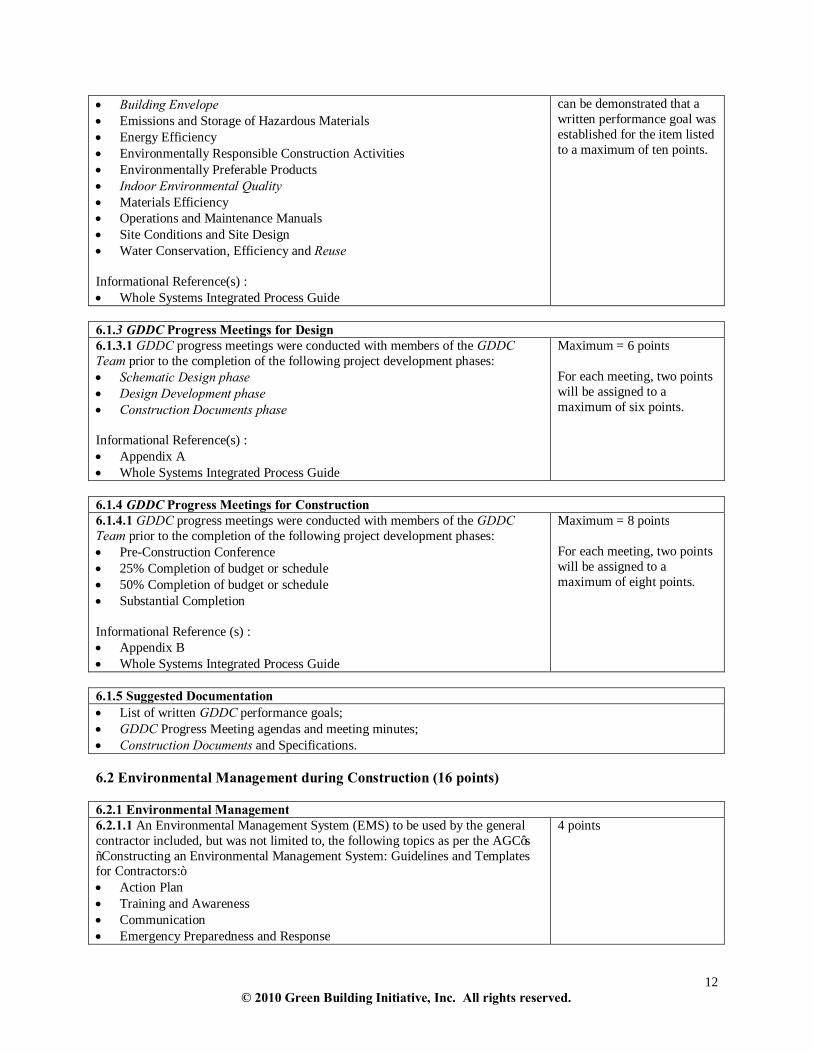
• Building Envelope • Emissions and Storage of Hazardous Materials • Energy Efficiency • Environmentally Responsible Construction Activities • Environmentally Preferable Products • Indoor Environmental Quality • Materials Efficiency • Operations and Maintenance Manuals • Site Conditions and Site Design • Water Conservation, Efficiency and Reuse Informational Reference(s) : • Whole Systems Integrated Process Guide
can be demonstrated that a written performance goal was established for the item listed to a maximum of ten points.
6.1.3 GDDC Progress Meetings for Design 6.1.3.1 GDDC progress meetings were conducted with members of the GDDC Team prior to the completion of the following project development phases: • Schematic Design phase • Design Development phase • Construction Documents phase Informational Reference(s) : • Appendix A • Whole Systems Integrated Process Guide
Maximum = 6 points For each meeting, two points will be assigned to a maximum of six points.
6.1.4 GDDC Progress Meetings for Construction 6.1.4.1 GDDC progress meetings were conducted with members of the GDDC Team prior to the completion of the following project development phases: • Pre-Construction Conference • 25% Completion of budget or schedule • 50% Completion of budget or schedule • Substantial Completion Informational Reference (s) : • Appendix B • Whole Systems Integrated Process Guide
Maximum = 8 points For each meeting, two points will be assigned to a maximum of eight points.
6.1.5 Suggested Documentation • List of written GDDC performance goals; • GDDC Progress Meeting agendas and meeting minutes; • Construction Documents and Specifications. 6.2 Environmental Management during Construction (16 points) 6.2.1 Environmental Management 6.2.1.1 An Environmental Management System (EMS) to be used by the general contractor included, but was not limited to, the following topics as per the AGC’s “Constructing an Environmental Management System: Guidelines and Templates for Contractors:” • Action Plan • Training and Awareness • Communication • Emergency Preparedness and Response
4 points

13 © 2010 Green Building Initiative, Inc. All rights reserved.
6.2.2 Clean Diesel Practices 6.2.2.1 Mandatory regulatory requirements were supplemented by including engine idle reduction strategies, use of clean alternative fuels (such as biodiesel and ULSD), and/or engine retrofits and repower. Informational Reference (s) : • US EPA National Clean Diesel Campaign
1 point
6.2.3 Building Materials and Building Envelope 6.2.3.1 The following measures were implemented: • Building materials made of organic or absorptive materials (such as wood,
plasterboard or insulation) or other building materials that collect organic matter (such as leaves or insects) are protected in transit and at the construction site from moisture. The building envelope was weather-tight and permitted to dry to manufacturers’ recommendations before installation of interior walls, wood floors or ceilings or HVAC systems.
Maximum = 2 points For each criteria met, one point will be assigned to a maximum of two points.
6.2.4 Indoor Air Quality 6.2.4.1 The specifications require that either of the following measures be implemented: • Flush the building with 100% outdoor air for 14 consecutive calendar days
immediately prior to occupancy, then change all air filters after completion of all construction activities but immediately prior to occupancy.
OR • After construction completion conduct a Baseline Indoor Air Quality test in
accordance with the United States Environmental Protection Agency "Testing for Indoor Air Quality”, section 01 81 09, December 2007, and confirm acceptable air quality with Baseline Indoor Air Quality test documentation.
4 points
6.2.4.2 For new construction, major renovations and additions, the specifications require that the following measure be implemented: • Control air and dust contaminants (including odors or irritants generated
during renovations) by one or more of the following five basic strategies outlined in SMACNA‘S “IAQ Guidelines for Occupied Buildings Under Construction Second Edition 2007”: - HVAC protection - Source control - Pathway interruption - Housekeeping - Scheduling
Maximum = 5 points For each strategy employed, one point will be assigned to a maximimum of five points.
6.2.5 Suggested Documentation • EMS plan to be used by the General Contractor; • Description of supplemental clean diesel practices; • Construction documents; • Manufacturer’s specifications, cut sheets and performance documentation; • Photographs of protected building materials; • Baseline Indoor Air Quality test.
6.3 Whole Building Commissioning (42 points) 6.3.1 Pre-Commissioning 6.3.1.1 The following measures were implemented: 3 points

14 © 2010 Green Building Initiative, Inc. All rights reserved.
• The owner’s project requirements for building systems were documented in accordance with ASHRAE Guideline 0-05: ANNEXES I and J.
• The building’s basis of design for building systems was documented in accordance with ASHRAE Guideline 0-05: ANNEX K.
• An Independent Commissioning Authority as defined in ASHRAE Guideline 0-05 reported directly to the owner.
6.3.2 Whole Building Commissioning 6.3.2.1 The Building Envelope (roofing assemblies, waterproofing assemblies, fenestrations and doors and cladding/skin) was commissioned in the pre-design, design and construction phase in accordance with ASHRAE/NIBS Guideline 0-05: Article 5, 6 and 7.
5 points
6.3.2.2 The HVAC&R Systems were commissioned in the pre-design, design and construction phase in accordance with ASHRAE/NIBS Guideline 0-05: Article 5, 6 and 7.
5 points
6.3.2.3 The Structural System was commissioned in the pre-design, design and construction phase in accordance with ASHRAE/NIBS Guideline 0-05: Article 5, 6 and 7.
4 points
6.3.2.4 The Fire Protection System was commissioned in the pre-design, design and construction phase in accordance with ASHRAE/NIBS Guideline 0-05: Article 5, 6 and 7.
4 points
6.3.2.5 The Plumbing System was commissioned in the pre-design, design and construction phase in accordance with ASHRAE/NIBS Guideline 0-05: Article 5, 6 and 7.
3 points
6.3.2.6 The Electrical System was commissioned in the pre-design, design and construction phase in accordance with ASHRAE/NIBS Guideline 0-05: Article 5, 6 and 7.
3 points
6.3.2.7 The Lighting System was commissioned in the pre-design, design and construction phase in accordance with ASHRAE/NIBS Guideline 0-05: Article 5, 6 and 7.
3 points
6.3.2.8 The following building systems were commissioned in the pre-design, design and construction phase in accordance with ASHRAE/NIBS Guideline 0-05: Article 5, 6 and 7. • Interior Systems • Elevating and Conveying Systems • Communication Systems
Maximum = 6 points or n/a For each building system commissioned, two points will be assigned to a maximum of six points. n/a for elevating and conveying systems only
6.3.2.9 Field testing of partitions for noise isolation was performed according to ASTM E 336-07, determined by ASTM E 413-04, and rated for not less than two-thirds STC value indicated. Partitions were adjusted and fitted to comply with test method requirements.
2 points
6.3.2.10 Building system specifications were commissioned in accordance with ASHRAE Guideline 0-05:ANNEX L.
2 points
6.3.2.11 Training on commissioned systems took place in accordance with ASHRAE Guideline 0-05: Article 7.2.14.
2 points
6.3.3 Suggested Documentation • Commissioning reports; • Construction documents; • Manufacturer’s specifications, cut sheets and performance documentation.

15 © 2010 Green Building Initiative, Inc. All rights reserved.
6.4 Environmental Management – Post Construction (14 points) 6.4.1 Operations and Maintenance Manuals 6.4.1.1 An Operations and Maintenance Manual was written that included the following plans, protocols, contracts and strategies: • Calibration Strategy for Outdoor and Exhaust Air Dampers • Carbon Dioxide Monitoring Protocol • Carbon Monoxide Monitoring Protocol • Chemical Management and Minimization Policy • Cooling Tower Operating Agreement • Energy Metering Reporting Plan • Food and Material Waste Reduction Plan • Frost Mitigation Strategy for Ventilation Heat Recovery • Low-Impact Site and Green Building Exterior Management Plan • Operating Schedule for all EPA WaterSense/Smart Water Application
Technology (SWAT) smart controllers (ET or soil moisture sensors) and automatic rain shut off devices.
• Integrated Pest Management Plan • Site Maintenance Contract • Waste Minimization Plan • Water Efficiency Measurement and Verification Plan • Schedule for HVAC and filter maintenance • General Housekeeping Informational Reference (s) : • Green Guide for HealthCare: Version 2.2; • GreenScapes for Large-scale Landscapes, U.S. EPA; • Appendices C to L.
Maximum = 14 points Fourteen points are earned when it can be demonstrated that a minimum of twelve of these plans, protocols, contracts and/or strategies are included in an Operations and Maintenance Manual.
6.4.2 Suggested Documentation • Operations and Maintenance Manual (including all plans, protocols, strategies and contracts).

16 © 2010 Green Building Initiative, Inc. All rights reserved.
7. SITE 7.1 Site Development Area (32 points) 7.1.1 Urban Infill, Urban Sprawl and Public Transportation 7 1.1.1 The building was constructed within a commercial zone or within 0.805 km (0.5 mi) of a commercial zone.
3 points
7.1.1.2 The site was located within 0.4 km (0.25 mi) of a public transportation facility such as a public bus stop or train-stop.
4 points
7.1.1.3 The following measures were implemented: • The site was located within 0.4 km (0.25 mi) of a public bicycle path or multi-
user path. OR • The site was located on a road with an existing dedicated bicycle lane. AND • Bicycle parking was installed in a sheltered area that enables users to lock the
frame and wheels of the bike for at least 5% of the maximum number of potential building occupants. If the building is multifamily residential, bicycle parking as described was installed for at least 50% of the units.
• The site has dedicated pedestrian access to connect or in the future will connect to community services, public transportation or both.
Maximum = 3 points For each measure implemented, one point will be assigned to a maximum of three points.
7.1.1.4 The building was constructed on a previously developed site served by existing utilities (electric power, water, and sewer) for a full year before construction began.
3 points
7.1.2 Greenfields, Brownfields and Floodplains 7.1.2.1 The building was constructed on a remediated brownfield or remediated Superfund site.
15 points
7.1.2.2 The undeveloped site was not farmland, a public park, a wooded area, prairie, or recreational area for at least three years prior to purchase or beginning of project.
3 points or n/a
7.1.2.3 The lowest level of any habitable space was located higher than the 100- year flood plain.
2 points
7.1.3 Suggested Documentation • Site civil plans and existing site civil plans; • Site plans that show the building, parking, street access, etc. and civil engineering plans that show topography,
drainage and infrastructure; • Documentation by EPA, municpal, or other governmental authority of Superfund and Brownfield site; • Construction documents; • Manufacturer’s specifications, zoning maps, cut sheets and performance documentation; • Pre-construction site documentation; • Landscaping plans; • Floodplain map.

17 © 2010 Green Building Initiative, Inc. All rights reserved.
7.2 Ecological Impacts (25 points) 7.2.1 Site Disturbance and Erosion 7.2.1.1 The following set of strategies were used during construction: • Silt fences were installed or fiber socks were filled with compost/wood chips
around the construction site and were maintained throughout construction. • Gravel pads were placed at all site entries and were cleaned throughout
construction. • Riprap was placed around all storm sewer outlets and silt and debris were
removed after each 24-hour rainfall of 5 mm (0.2 in) or more. • Disturbed soil was corrected using erosion control mats, or was mulched and
seeded within 90 days of being disturbed. • During dry days dust was controlled by wetting the soil each day for 15 to 30
minutes before construction activities began, and again after construction activities were done for the day.
OR • The civil engineer provided an erosion and sedimentation control plan that met or
exceeded all requirements outlined by the U.S EPA’s “Sediment and Erosion Control: An Inventory of Current Practices, National Pollutant Discharge Elimination System (NPDES) Permit Program” and was fully implemented by the general contractor.
Maximum = 5 points or n/a For each strategy implemented, one point will be assigned to a maximum of five points.
7.2.1.2 Construction fences were installed around trees and shrubs that were to be retained on the site, and extended at least 1.5 times the radius of the drip line or the critical root zone (when known) to protect plant roots. OR • A certified arborist provided a tree preservation plan that was fully implemented
by the general contractor. Informational Reference (s): • Invasive Plant Atlas of the United States
2 points or n/a
7.2.1.3 Construction activities did not go beyond 12.2 m (40 ft) of the building footprint and remained within 1.5 m (5 ft) of parking lots, roadways, sidewalks and utility right-of-ways except where the intent of the construction activities was one or more of the following: • To remove invasive plant species. • To replace parking lots, driveways, or sidewalks with vegetated spaces. • To restore prairie or wetlands. • To increase on-site water retention by building rain gardens, swales, retention
ponds, or berms.
2 points

18 © 2010 Green Building Initiative, Inc. All rights reserved.
7.2.2 Heat Island Effect 7.2.2.1 Vegetated space was increased by 10% (expressed as a percent of the total site area) and did not contain any invasive species.
2 points or n/a
7.2.2.2 The following measures were implemented: • For buildings located in Climate Zones 1 through 5, 40% or more of the
exposed opaque surface of a low slope roof cover was installed with a vegetated roof complying with ASTM E2400-06 and/or roofing surface/material having a Solar Reflectance Index (SRI) of 78 or greater.
OR • For buildings located in Climate Zones 1 through 5, 40% or more of the
exposed opaque surface of a steep slope roof cover was installed with a vegetated roof complying with ASTM E2400-06.
OR • For buildings located in Climate Zones 1 through 5, 75% or more of the
exposed opaque surface of a steep slope roof cover was installed with or a roofing surface/material having an SRI of 29 or greater.
Maximum = 6 points 40% -55% = 2 points 56% -70% = 4 points >71% = 6 points OR 4 points for 75% @ SRI>29
7.2.2.3 For sites with more than 30% paved surfaces (including parking lots, sidewalks and driveways outside of building footprint), a minimum of 50% of the paved surfaces had an SRI of 29 or higher.
2 points or n/a
7.2.2.4 For sites with more than 30% paved surfaces (including parking lots, sidewalks and driveways outside of building footprint), a minimum of 50% of all paved surfaces will be shaded by trees within fifteen years.
3 points or n/a
7.2.2.5 For buildings located in Climate Zones 1 through 5, at least 75% of the opaque wall surfaces on the east and west have an SRI of 29 or greater.
1 point
7.2.3 Bird Collisions 7.2.3.1 Measures to address bird collisions included, but were not limited to, the following: • The building did not have any points with an unobstructed view through from
one exposure to the opposite exposure. • Non-reflective glass assemblies were installed.
Informational Reference: • New York City Audobon’s Bird Safe Building Guidelines • Chicago’s Bird-Safe Building Design Guide for New Construction and
Renovation
Maximum = 2 points For each measure implemented, 1 point will be assigned to a maximum of 2 points.
7.2.4 Suggested Documentation • Construction documents; • Manufacturer’s specifications, cut sheets, and performance documentation; • Photo-documentation; • Site civil plans; • Manufacturer’s specifications and/or interior design plans that show interrupted spaces • Pre-contruction documentation; • Erosion and Sediment Control plan; • Landscape plans; • Shade site plan; • Roofing plans.

19 © 2010 Green Building Initiative, Inc. All rights reserved.
7.3 Watershed Features (27 points) 7.3.1 Storm Water Management 7.3.1.1 The following measures were implemented: • At least 70% of the storm water runoff from the roof, parking lots, and
sidewalks and other impervious areas was diverted to a rain garden or swale, retention basin or pervious pavement or cistern for reuse before it reached the storm sewer. - For sites with silt and/or sandy soils (as determined by a 25-Year, 24-hour
storm event, 15.2 cm (6 in) percolation test) rain gardens, swales or pervious pavement did not cover more than 20% of the site area. and
- For sites where the average monthly rainfall during the wet season does not exceed 15.2 cm (6 in), stormwater infiltrates, evapotranspirates or is stored for reuse at least 3.8 cm (1.5 in) of rain water.
AND/OR
- For sites with higher average monthly rainfall during the wet season, the retention basin or pervious pavement was sized to accommodate at least 6.4 cm (2.5 in) of rain water released on site in a 24-hour period.
OR • The civil engineer provided calculations to demonstrate the site, once plantings
have been established for five years, can evapotranspirate a 24-hour rain event without releasing any discharge to storm sewer or to adjacent properties with the intent to improve water quality over preconstruction runoff
10 points
7.3.1.2 Site boundaries were not located within 30.5m (100ft) of a natural fresh or salt water body (including oceans, lakes, rivers, streams, estuaries, bays, or isolated wetlands) except for retention ponds, restored wetlands, and/or man-made water features that received all storm water run-off or where site boundaries had permanent continuous earth or concrete berms that rose at least 40.6 cm (16 in) higher than surrounding grade to prevent runoff.
8 points
7.3.1.3 A vegetated roof was installed on at least 1% of the roof area. Informational Reference (s): • ASTM E2399-08 • ASTM E2400-06
Maximum = 9 points 1% -10% = 1 point 11% - 20% = 2 points 21% - 30% = 3 points 31% - 40% = 4 points 41%-50% = 5 points 51% - 60% = 6 points 61%-70% = 7 points 71%-80% = 8 points >81% = 9 points
7.3.2 Suggested Documentation • Roofing plans; • Percolation test results; • Site plans; • Area rainfall charts; • Storm water discharge plan.

20 © 2010 Green Building Initiative, Inc. All rights reserved.
7.4 Site Ecology (28 points) 7.4.1 Landscape and Irrigation For section 7.4.1, complete the most applicable of the following seven paths. PATH 1 7.4.1.1 Site has only impervious surfaces outside the building footprint, and therefore no potential to landscape or irrigate.
0 points If 7.4.1.1 is applicable, proceed to 7.5.1
For 7.4.1.2 through 7.4.1.7, exterior vegetated space means outside the building footprint and paved areas. Applies only to sites where the building footprint including paved areas is 50% or less of the site. PATH 2 7.4.1.2 100% of the exterior vegetated space was left in its natural state and was not irrigated.
28 points or n/a If 7.4.1.2 is applicable, proceed to 7.5.1
PATH 3 7.4.1.3 75-99% of the exterior vegetated space was left in its natural state and was not irrigated.
21 points or n/a If 7.4.1.3 is applicable, proceed to 7.4.1.3.1.
7.4.1.3.1 Complete 7.4.1.8.1 to 7.4.1.9.5 for additional points.
Maximum points = points obtained from (7.4.1.8.1 to 7.4.1.9.5) *0.25
PATH 4 7.4.1.4 50-74% of the exterior vegetated space was left in its natural state and was not irrigated.
14 points or n/a If 7.4.1.4 is applicable, proceed to 7.4.1.4.1.
7.4.1.4.1 Complete 7.4.1.8.1 to 7.4.1.9.5 for additional points.
Maximum points = points obtained from (7.4.1.8.1 to 7.4.1.9.5)*0.50
PATH 5 7.4.1.5 25-49% of the exterior vegetated space was left in its natural state and was not irrigated.
7 points or n/a If 7.4.1.5 is applicable, proceed to 7.4.1.5.1.
7.4.1.5.1 Complete 7.4.1.8.1 to 7.4.1.9.5 for additional points.
Maximum points = points obtained from (7.4.1.8.1 to 7.4.1.9.5)*0.75

21 © 2010 Green Building Initiative, Inc. All rights reserved.
PATH 6 7.4.1.6 All exterior vegetated spaces were landscaped and/or irrigated.
0 points If applicable, proceed to 7.4.1.8.1
PATH 7 7.4.1.7 All exterior vegetated spaces of a previously degraded site were restored with native, adaptive and/or non-invasive plant species to a natural condition mimicking predevelopment conditions.
Maximum = 28 points or n/a 25%-49% = 7 points 50%-74% = 14 points 75%-99% = 21 points 100% = 28 points
7.4.1.8 Landscaping 7.4.1.8.1 A Landscape and Irrigation Plan was developed by a landscape architect, certified horticulturalist, or certified irrigation professional. Informational Reference (s):
• Florida Yards and Neighborhood’s Program: “A Guide to Florida Friendly Landscaping: Florida Yards and Neighborhoods Handbook”;
• Local Cooperative Extension Research, Education and Extension Service; • State or local agency landscaping reference guide.
2 points
7.4.1.8.2 The plant palette included the following measures: • Site characteristics (e.g. soil type, drainage). • Review of structural limitations (e.g. utilities, overhangs, lights) that would
impact the growth and location of plantings. • Plants were from a local or regional plant list such as from a university,
water agency or nursery growers association or listed by State or region as a native species.
• Moderate to high drought tolerant plants were used. • Salvaged plants were identified as non-invasive. • New plantings were native and non-invasive (as defined by the National
Parks Service/Department of the Interior’s WeedUS - Database). • Turf grass was limited to within 6.1 m (20 ft) of buildings and does not
extend beyond 1.5 m (5 ft) from parking lots, driveways, walkways, rain gardens, swales, and retention ponds.
Informational Reference (s):
• Florida Yards and Neighborhood’s Program: “A Guide to Florida Friendly Landscaping: Florida yards and Neighborhoods Handbook;”
• State and local university or college landscape reference guide; • State or local agency landscaping reference guide.
8 points
7.4.1.8.3 Landscaped areas were installed with at least 15.2 cm (6 in) of soil and were aerated, tilled and/or broken up.
1 point
7.4.1.8.4 Landscaped areas, not including preserved or natural areas, were covered with organic mulch that is an appropriate type for the plants being mulched and locally-approved in those areas where jurisdictions offer a standard. Mulch was applied 7.6 cm to 10.2 cm (3- 4 in) deep around plants and trees, with 5.1 cm (2 in) clear around each plant. Informational Reference (s): • State or local university college landscape reference guide;
1 point

22 © 2010 Green Building Initiative, Inc. All rights reserved.
• State or local agency landscaping landscape reference guide; • Florida Yards and Neighborhood’s Program: “A Guide to Florida Friendly
Landscaping: Florida Yards and Neighborhoods Handbook.” 7.4.1.8.5 Plants with similar water and maintenance requirements were grouped. The plants were grouped and spaced to allow for maturation at a 5-year growth rate.
2 points
7.4.1.8.6 Retained trees, clusters of trees and undergrowth that were adapted or native to the ecosystem were integrated into the landscape plan.
3 points
7.4.1.8.7 15% of planned impervious walkways, patios and driveways were installed with pervious materials such as clay or concrete pavers with pervious joints/openings, bricks, gravel, turf-block, mulch, or pervious concrete.
1 point
7.4.1.9 Irrigation 7.4.1.9.1 The need for irrigation or watering of exterior vegetated spaces was eliminated through plant selection, site design and landscaping practices that preserve the natural environment.
Maximum = 10 points or n/a Only applicable for paths 3 through 6. If 7.4.1.9.1 is applicable, proceed to 7.5.1. If 7.4.1.9.1 is not applicable, Proceed to 7.4.1.9.2.
7.4.1.9.2 One or more of the following systems were installed: • A permanent irrigation system with an onsite cistern and/or rainwater
harvesting system. • A permanent irrigation system capable of using only reclaimed water. • Gutter downspouts and roof runoff not directed to rainwater harvesting systems
designed to be directed into planted areas or other landscape features capable of retaining runoff.
Maximum = 3 points or n/a For each permanent irrigation system installed, one point will be assigned to a maximum of three points.
7.4.1.9.3 Swing joints or flex pipes were used on all in-ground irrigation heads.
1 point
7.4.1.9.4 EPA WaterSense/Smart Water Application Technology (SWAT), smart controllers (ET, rain sensors or soil moisture sensors) and automatic rain shut off devices were installed.
1 point
7.4.1.9.5 The irrigation system design and installation met the Irrigation Association’s “Turf and Landscape Irrigation Best Management Practices 2005”: section 2, 3.
5 points or n/a

23 © 2010 Green Building Initiative, Inc. All rights reserved.
7.4.2 Suggested Documentation • Pre-Construction documentation of site; • Construction documents; • Landscape architect /designer approved Landscape and irrigation plan; • Plant palette; • Manufacturer’s specifications, cut sheets, and performance documentation; • Local or regional plant list; • Site plans. 7.5 Exterior Light Pollution (7 points) 7.5.1 Exterior Light Pollution 7.5.1.1 All exterior lighting fixture’s photometric nadir aimed at angles other than straight down had a combined output of 10,000 lumens or less, except where lights were required by codes or government officials for safety or security.
3 points or n/a
7.5.1.2 All exterior lighting fixtures with lamps having a mean output of 10,000 lumens or more were full cutoff types (as defined by IESNA) and were aimed straight down except where lights were required by codes or government officials for safety or security.
2 points or n/a
7.5.1.3 The following measures were implemented: • All full cutoff fixtures aimed straight down were located at a distance of at least
twice their mounting height from the property line. Ensure compliance to ANSI/ASHRAE/IESNA Standard 90.1-2007. All output from fixtures are limited to 0.5 foot-candles on adjacent properties.
OR • An electrical or lighting engineer provided a site lighting plan that graphically
shows that reflected light on adjacent properties is limited to less than 0.5 foot-candles from all on-site fixtures. Additionally, all walls and roofs illuminated by these lights were located at a distance of at least twice their mounting height from the property line.
2 points or n/a
7.5.2 Suggested Documentation • Exterior lighting plans; • Electrical Engineer’s site lighting plan with illuminance computations spaced no more than 10 ft. apart; • Zoning ordinance requirements. 8. ENERGY Performance Design Option PATH A – 300 points available (150 minimum required points)
Prescriptive Design Option PATH B – 250 points available (100 minimum required points)
8.1 Building Carbon Dioxide Equivalent (CO2e) Emissions 8.2 Demand Reduction 8.3 Measurement & Verification
8.4-8.8 Prescriptive Design Criteria 8.9. Renewable Energy
Both the Performance Design Option (Path A) and the Prescriptive Design Option (Path B) requires that the proposed building design comply with ANSI/ASHRAE/IESNA Standard 90.1-2007 or the local energy code. BEGIN PERFORMANCE PATH A – Performance Design Option (300 points)

24 © 2010 Green Building Initiative, Inc. All rights reserved.
8.1 Building Carbon Dioxide Equivalent (CO2e) Emissions – PATH A (250 points) 8.1.1 Percent Reduction in Carbon Dioxide Equivalent (CO2e) Emissions 8.1.1.1 The building had more than a 50% reduction in carbon dioxide equivalent emissions over the baseline building for its geographical location. This reduction was calculated using the following formula: Percent reduction in CO2e =100 X (1 – PER/BER), where: • The Baseline Equivalent Emission (BER) Rate is the baseline building’s carbon
dioxide equivalent emission rate. • PER is the proposed building’s carbon dioxide equivalent emission rate. • PER is less than BER. Baseline Equivalent Emission Rate (BER) Calculations BER is calculated using the following formula: BER = (baseline Energy Use Intensity (EUI)) X product of [ (percentage of each fuel in the annual energy fuel mix for the planned building type and location) X (CO2e Emission Factor for each fuel) ], where: • The baseline building’s site Energy Use Intensity (EUI) is determined using
ENERGY STAR Target Finder. • The baseline building’s site EUI is 50% better than the Energy Performance
Rating (Target Finder) score of 50. • The annual energy fuel mix for the baseline building is determined from DOE-
EIA and reported at the top of Target Finder’s Results page. • The CO2e emission factor for each fuel in the baseline building’s annual energy
fuel mix can be found in Table 8.1.1- A.
Proposed Equivalent Emission Rate (PER) Calculations PER is calculated using the following formula: PER = (proposed EUI) X product of [ (percentage of each fuel in the annual energy fuel mix for the proposed building) X (CO2e Emission Factor for each fuel) ], where:
The proposed building’s Energy Use Intensity (EUI) is calculated using a computer-based simulation program that conforms to the requirements outlined in Section 506 of the 2009 International Energy Conservation Code or ANSI/ASHRAE/IESNA Standard 90.1-2007, Appendix G, Section G2.2. Proposed Building’s Equivalent Emission Rate (PER) shall be determined by performing a EUI calculation for the proposed building using the energy performance requirements specified by Table G3.1 Modeling Requirements for Calculating Proposed and Baseline Building Performance in ANSI/ASHRAE/IESNA Standard 90.1-2007. Only the Proposed Building Performance column shall be used for modeling the PER.
• The annual energy fuel mix planned for the proposed building is what is to be used for this calculation.
• The CO2e emission factor for each fuel in the proposed building’s annual energy fuel mix can be found in Table 8.1.1- A of this document.
Maximum = 250 points For a 50% reduction in CO2e emissions, 150 points will be assigned. For every 1% reduction in CO2e emissions above 50%, 2 points will be assigned to a maximum of 250 points.

25 © 2010 Green Building Initiative, Inc. All rights reserved.
Table 8.1.1 - A: CO2e Emission Factors Fuel CO2e Emission Factor
kg/kWh (lb/kWh) Biomass 0.026 (0.057)2 Coal (bituminous) 0.373 (0.822)1 Coal (lignite) 0.585 (1.289)1 Fuel oil (residual) 0.311 (0.686)1 Fuel oil (distillate) 0.299 (0.660)1 Gasoline 0.326 (0.719)1 Grid-delivered electricity 0.758 (1.670)1 Grid- displaced electricity3 -0.833 (-1.835)1 LPG 0.274 (0.602)1 Natural gas 0.232 (0.510)1 Off-site renewable electricity4 -0.758 (-1.670)1 Waste heat5 0.019 (0.042)2 1 Deru, M., P. Torcellini. 2007. Source Energy and Emissions Factors for Energy Use in Buildings. NREL/TP-550-38617, June 2007. Golden, CO. National Renewable Energy Laboratory. 2 L2A Conservation of Fuel and Power in New Buildings other than Dwellings. April 2006. Office of the Deputy Prime Minister, United Kingdom. 3 Grid displaced electricity comprises all electricity generated at the building site by, for example PV panels, wind-power, combined heat and power systems (CHP), etc. The associated CO2e emissions are subtracted from the total CO2e emissions for the building before determining the PER. CO2e emissions arising from fuels used by the building’s power generation system (e.g., to power the CHP plant) must be included in the building’s CO2e emission calculations. 4 The associated CO2e emissions from off-site renewable electricity (e.g., using renewable energy certificates or “greenpower”) are subtracted from the total CO2e emissions for the building before determining the PER. Contracts must have a duration of at least three years. Only 25% of off-site renewable electricity can be credited to the proposed building’s CO2e calculation. 5 This includes waste heat from industrial processes and power stations rated at more than 10MWe and with a power efficiency of greater than 35%. 8.1.2 Suggested Documentation • Energy simulation program’s input and results; • ENERGY STAR Target Finder results; • PER, BER, and CO2e emission reduction calculations.

26 © 2010 Green Building Initiative, Inc. All rights reserved.
8.2 Demand – PATH A (40 points) 8.2.1 Passive Demand Reduction 8.2.1.1 For buildings located in Climate Zones 1 through 5, thermal mass in wall construction was used in the following ways: • A minimum of 20% of the building envelope gross wall area had a heat capacity
of 7 Btu/ft2 °F(143 kJ/m2K) or greater. OR • Provided that the walls have a material unit weight not greater than 120 lb/ft3
(1920 kg/m3), a minimum of 20% of the building envelope gross wall area had a heat capacity of 5 Btu/ft2 °F (102 kJ/m2K).
Informational Reference (s): • ANSI/ASHRAE/IESNA Standard 90.1 – 2007
4 points or n/a n/a for Climate Zones 6-8
8.2.1.2 For buildings located in Climate Zones 1 through 5, thermal mass in wall construction was used in the following ways:
• Mass walls used as interior partitions, had a surface area equal to at least 20% of the building envelope gross wall area. Mass walls had a heat capacity of 7 Btu/ft2 °F (143 kJ/m2K) or greater. An insulating material or wallboard was not used as an interior finish on these walls.
OR • Mass walls used as interiors partition, had a surface area equal to at least 20% of
the building envelope gross wall area. Mass walls had a heat capacity of 5 Btu/ft2 °F (102 kJ/m2K) and a material unit weight not greater than 120 lb/ft3 (1900 kg/m3 ) with the portion of the wall with the greatest heat capacity exposed to conditioned air. An insulating material or wallboard was not used as an interior finish on these walls.
4 points or n/a n/a for Climate Zones 6-8
8.2.1.3 For buildings located in Climate Zones 1 through 5, thermal mass in floor construction was used in the following ways: • A minimum of 50% of the return air plenums were located directly in contact
with a floor or wall having a heat capacity of at least 7 Btu/ft2 °F (143 kJ/m2K). OR • A minimum of 50% of the return air plenums were located directly in contact
with a floor or wall having a heat capacity of 5 Btu/ft2 °F (102 kJ/m2K),, and the wall or floor had a material unit weight not greater than 120 lb/ft3 (1920) kg/m3 .
4 points or n/a n/a for Climate Zones 6-8
8.2.2 Thermal Energy Storage System 8.2.2.1 For buildings located in Climate Zones 1 through 5, a thermal energy storage system was used that is capable of offsetting the peak cooling demand by greater than 30%.
12 points or n/a >30% = 4 points >40% = 8 points >50% = 12 points n/a for Climate Zones 6-8
8.2.3 Power Demand Reduction 8.2.3.1 The building’s monthly power demand factor (lowest kW demand month ÷ peak kW demand month) was determined to be greater than the average of one of the following: • 0.75 • 0.85
Maximum = 8 points >0.75 = 4 points >0.85 = 8 points
8.2.4 Demand Capable Energy Management System

27 © 2010 Green Building Initiative, Inc. All rights reserved.
8.2.4.1 One of the following measures was implemented: • An Energy Management System was installed and programmed to reduce power
demand below the non-reduced peak by 15% or 30% in the building. OR • Power demand is controlled by the electric utility and there is a 15% or 30% load
shedding agreement.
Maximum = 8 points 15% = 4 points 30% = 8 points
8.2.5 Suggested Documentation • Construction documents; • Manufacturer’s specifications, cut sheets, and performance documentation; • Energy simulation program results; • Power demand factor calculations. 8.3 Measurement and Verification – PATH A (10 points) 8.3.1 Measurement and Verification Protocol 8.3.1.1 The Energy Metering Reporting Plan in the Operations and Maintenance Manual included the following operations and anticipated energy demand and consumption characteristics: • Lighting and lighting controls: daily demand and consumption by floor or by
zones with floor areas no greater than 1860 m2 (20,000 ft2). • Plug loads: daily demand and consumption by floor or by zones no greater than
1860 m2 (20,000 ft2). • Major electric HVAC equipment (chillers, cooling towers, AHU fans, pumps), 5
HP or greater; seasonal peak demand and monthly consumption. • Chilled water generation: seasonal peak output and monthly consumption. • On-site renewable energy power generation: monthly peak output, monthly
production, and site specific weather characteristics (e.g., irradiance, wind, and temperature).
• Heating water or steam generation: seasonal peak and monthly consumption. • Secondary electric HVAC equipment as appropriate (e.g., heat pumps, fan coils,
fan powered boxes): operational status. • Speciality or process electrical equipment: daily demand and consumption. • Critical HVAC controls (e.g., scheduling, economizer operation, temperature
resets): status monitoring and verification. Sub-metering equipment was installed for the building systems listed above.
8 points or n/a n/a for buildings less than 1860 m2 (20, 000 ft2)
8.3.1.2 A Measurement and Verification program was implemented in accordance with EVO’s “International Performance Measurement & Verification Protocol (IPMVP) Volume III: Concepts and Options for Determining Energy Savings in New Construction”: Option D, Calibrated Simulation (Savings Estimation Method 2), April 2003.
2 points or n/a n/a for buildings less than 1860 m2 (20, 000 ft2)
8.3.2 Suggested Documentation • Energy Metering Reporting Plan; • Measurement and Verification Program details; • Energy Certification or Label; • References to specifications and drawings of sub-metering equipment; • Cut sheets for meters and meter reading equipment; • Description of the monthly monitoring and verification reports that will be sent to building management. END OF PERFORMANCE PATH A BEGIN PRESCRIPTIVE PATH B - Prescriptive Design Option (250 points)

28 © 2010 Green Building Initiative, Inc. All rights reserved.
8.4 Building Opaque Envelope – PATH B (42 points) 8.4.1 Thermal Resistance and Transmittance 8.4.1.1 The thermal resistance and thermal transmittance for all opaque elements of the building envelope shall be demonstrated by the use of one of the following two methods: The rated R-value of the insulation added in the framing cavities and the continuous insulation (c.i.) uninterrupted by framing, where indicated, shall meet or exceed the values specified in Table 8.4.1-A. (The units for U- and R-values are inch-pound.) The U-factor, C-factor, or F-factor for the entire assembly shall meet or not exceed the values specified in Table 8.4.1-B.
12 points Meet or exceed the values in Table 8.4.1-A OR Meet or not exceed the values in Table 8.4.1-B
Table 8.4.1- A: Insulation Minimum R-values
Climatic Zones 1 2 3 4 5 6 7 8 Opaque Elements Roofs Insulation above Deck R-15.0 ci R-15.0 ci R-20.0 ci R-20.0 ci R-20.0 ci R-20.0 ci R-20.0 ci R-30.0 ci
Metal Building R-19.0 R-13.0 + R-13.0
R-13.0 + R-13.0
R-13.0 + R-19.0
R-13.0 + R-19.0
R-13.0 + R-19.0
R-30.0 + R-10.0 ci R-30.0 + R-10.0 ci
Attic and Other R-30.0 R-38.0 R-38.0 R-38.0 R-38.0 R-38.0 R-60.0 R-60.0 Walls Above Grade Mass NR R-7.6 ci R-9.5 ci R-11.4 ci R-11.4 ci R-11.4 ci R-15.2 ci R-15.2 ci
Metal Building R-16.0 R-16.0 R-6.0 + R-13.0
R-6.0 + R-13.0
R-13.0 + R-13.0
R-13.0 + R-13.0
R-13.0 + R-13.0 R-13.0 + R-16.0
Steel Framed R-13.0 R-13.0 R-13.0 + R-3.8 ci
R-13.0 + R-7.5 ci
R-13.0 + R-7.5 ci
R-13.0 + R-7.5 ci
R-13.0 + R-7.5 ci R-13.0 + R-21.6 ci
Wood Frame & Other R-13.0 R-13.0 R-13.0
R-13.0+ R-3.8 ci or R-19.0
R-13.0+ R-3.8 ci or R-19.0
R -13.0+ R-3.8 ci or R-19.0
R-13.0 + R-7.5 ci or R-20.0 + R-2.5 ci
R-13.0 + R-10.0 ci 0r R-20.0 + R-5.0 ci
Walls Below Grade Below Grade Wall NR NR NR NR R-7.5 ci R-7.5 ci R-7.5 ci R-15.0 ci Floors Mass NR R-6.3 ci R-8.3 ci R-8.3 ci R-10.4 ci R-10.4 ci R-12.5 ci R-16.7 ci Steel Joist R-19.0 R-19.0 R-19.0 R-30.0 R-30.0 R-30.0 R-38.0 R-38.0 Wood Frame & Other R-19.0 R-19.0 R-30.0 R-30.0 R-30.0 R-30.0 R-30.0 R-30.0
Slab-On-Grade Floors
Unheated NR NR NR NR NR R-10.0 for 24 in.
R-15.0 for 24 in. R-20.0 for 24 in.
Heated R-7.5 for 12 in.
R-7.5 for 12 in.
R-7.5 for 12 in.
R-7.5 for 24 in.
R-10.0 for 36 in.
R-10.0 for 36 in.
R-20.0 for 36 in. + R-5.0 ci below
R-20.0 for 36 in. + R-5.0 ci below
NR – No Requirement CI – Continuous Insulation

29 © 2010 Green Building Initiative, Inc. All rights reserved.
Table 8.4.1 – B: Maximum Assembly U-factors, C-factors and F-factors Climatic Zones 1 2 3 4 5 6 7 8 Opaque Elements Roofs Insulation above Deck U-0.063 U-0.063 U-0.048 U-0.048 U-0.048 U-0.048 U-0.048 U-0.032
Metal Building U-0.065 U-0.055 U-0.055 U-0.049 U-0.049 U-0.049 U- 0.028 U- 0.028 Attic and Other U-0.034 U-0.027 U-0.027 U-0.027 U-0.027 U-0.027 U-0.017 U-0.017 Walls Above Grade Mass U-0.580 U-0.123 U-0.104 U-0.090 U-0.090 U-0.090 U-0.071 U-0.071 Metal Building U-0.093 U-0.093 U- 0.070 U- 0.070 U-0.057 U-0.057 U-0.057 U-0.055 Steel Framed U-0.124 U-0.124 U-0.084 U-0.064 U-0.064 U-0.064 U-0.064 U- 0.040 Wood Frame & Other U-0.089 U-0.089 U-0.089 U-0.064 U-0.064 U-0.064 U-0.051 U-0.045
Walls Below Grade Below Grade Wall C-1.140 C-1.140 C-1.140 C-1.140 C-0.119 C-0.119 C-0.119 C-0.063 Floors Mass U- 0.332 U-0.107 U- 0.087 U- 0.087 U-0.074 U-0.074 U-0.064 U-0.051 Steel Joist U-0.052 U-0.052 U-0.052 U-0.038 U-0.038 U-0.038 U-0.032 U-0.032 Wood Frame & Other U-0.051 U-0.051 U-0.033 U-0.033 U-0.033 U-0.033 U-0.033 U-0.033
Slab-On-Grade Floors Unheated F-0.730 F-0.730 F-0.730 F-0.730 F-0.730 F-0.540 F-0.520 F-0.510 Heated F-1.020 F-1.020 F-1.020 F-0.950 F-0.840 F-0.840 F- 0.373 F- 0.373 Opaque Doors Swinging U-0.700 U-0.700 U-0.700 U-0.700 U-0.700 U-0.700 U-0.600 U-0.500 Non-Swinging U-1.450 U-1.450 U-1.450 U-0.500 U-0.500 U-0.500 U-0.500 U-0.500 8.4.2 Orientation 8.4.2.1 The building was oriented such that the ratio of the north/south fenestration area to the east/west fenestration area was between 1.25 and 2.00
Maximum = 6 points or n/a 1.25 = 1 point 1.40 = 2 points 1.55 = 3 points 1.70 = 4 points 1.85 = 5 points 2.00 = 6 points n/a where site factors do not allow or favor orientation adaptations.

30 © 2010 Green Building Initiative, Inc. All rights reserved.
8.4.3 Fenestration Systems 8.4.3.1 The thermal transmittance (U-factors) of the building’s fenestration system was less than or equal to the values in Table 8.4.3-A.
12 points The overall values are calculated based on a weighted area average of the assemblies.
8.4.3.2 The Solar Heat Gain Coefficient (SHGC) of the building’s fenestration system was less than or equal to the values in Table 8.4.3-A.
12 points The overall values are calculated based on a weighted area average of the assemblies
Table 8.4.3 – A: Building Envelope Requirements: Fenestration
CLIMATE ZONE 1 2 3 4 Except Marine
5 And Marine 4
6 7 8
Vertical Fenestration (40% maximum of above-grade wall) U-factor Framing materials other than metal with or without metal reinforcement or cladding U-factor 1.20 0.75 0.65 0.40 0.35 0.35 0.30 0.30 Metal framing with or without thermal break Curtain / Storefront U-factor 1.20 0.70 0.60 0.50 0.45 0.45 0.40 0.40
Entrance Door U 1.20 1.10 0.90 0.85 0.80 0.80 0.75 0.75 All Other U-Factora 1.20 0.75 0.65 0.55 0.50 0.50 0.45 0.45 SHGC-All Frame Types SHGC: Northb 0.45 0.45 0.45 0.50 0.50 0.50 0.65 NR SHGC: E, S & W PF < 0.25 0.25 0.25 0.25 0.40 0.40 0.40 0.50 NR
SHGC: E, S & W 0.25 ≤ PF <0.5 0.30 0.30 0.30 0.50 0.50 0.50 NR NR
SHGC: E, S & W PF ≥ 0.5 0.40 0.40 0.40 0.65 0.65 NR NR NR
Skylights (3% maximum) U-factor 0.75 0.75 0.65 0.60 0.60 0.60 0.60 0.50 SHGC 0.20 0.20 0.30 0.40 0.40 0.50 0.60 NR NR = No requirement. PF = Projection factor a. All other includes operable windows, fixed windows and non-entrance doors. b. North-Facing within 45 degrees of true north (Northern Hemisphere). 8.4.4 Suggested Documentation • Site plans; • Construction documents; • Manufacturer’s specifications, cut sheets, and performance documentation.

31 © 2010 Green Building Initiative, Inc. All rights reserved.
8.5 Daylighting – PATH B (15 points) 8.5.1 Daylighting 8.5.1.1 The sidelit daylighted area and toplit daylighted area was a minimum of 10% of the net building area.
Maximum = 8 points or n/a 10% -15% = 1 point 16% - 21% =2 points 22% - 27%=3 points 28% - 32%=4 points 33% - 38%=5 points 39% - 44% = 6 points 45% -50% =7 points >50% = 8 points n/a for buildings or areas which would be functionally compromised by daylighting
8.5.1.2 Buildings located in climate zones 1, 2, 3A,3B were determined to have, at a minimum, an effective aperture for vertical fenestration of 0.10 EAvf. Buildings located in climate zones 3C, 4, 5, 6, 7, 8 were determined to have, at a minimum, an effective aperture for vertical fenestration of 0.15 EAVF.
4 points or n/a n/a if there are no windows and for spaces other than offices and classrooms
8.5.1.3 Between 2-6% of the roof area was installed with skylights. Informational Reference (s): • ANSI/ASHRAE/IESNA Standard 90.1 – 2007 • 2009 International Energy Conservation Code (IECC)
3 points or n/a n/a if building is located in Climate Zone 7 and 8
8.5.2 Suggested Documentation • Construction documents; • Manufacturer’s specifications, cut sheets, and performance documentation; • Effective aperture for vertical fenestration calculations.

32 © 2010 Green Building Initiative, Inc. All rights reserved.
8.6 HVAC Systems and Controls – PATH B (84 points) In sections 8.6.1.1 and 8.6.1.2, points are awarded for selecting efficient cooling systems. Table 8.6.1.1 awards points for selecting an efficient base system (the types of systems and their base efficiencies are identified in ASHRAE Standard 90.1, Section 6.8.1). Table 8.6.1.2 awards points for improving the full-load and part-load efficiency of the base system through particular equipment selection. It provides points for equipment efficiency improvement for Full-Load, Part-Load (Seasonal), or both, with maximum points only possible when both Full-Load and Part-Load efficiency is improved. 8.6.1 Cooling Equipment 8.6.1.1 ASHRAE Standard 90.1-2007 (with addenda) efficiency requirements were used to determine Base Efficiency.
Table 8.6.1.1 Cooling Equipment Base Efficiency
Maximum = 5 points or n/a
COP EER SEER Points
>=2 to <3 >=6.8 to <10.2 >=10 to <13 1 >= 3 to <4 >=10.2 to <13.7 >=13 to <16 2 >= 4 to <5 >=13.7 to <17 >=16 to <20 3 >= 5 to <6 >=17 to <20 >=20 to <23 4
>= 6 >=20 >=23 5 Some water chiller equipment efficiency is presented in kW/TR units. To convert to COP, divide 3.516 by the kW/TR [COP = 3.516 / (kW/TR)]
Maximum = 5 points or n/a For system designs with mixed cooling equipment types, the points shall be the weighted average based on equipment cooling capacity. n/a where there is no cooling equipment
8.6.1.2 Incremental efficiency improvement was demonstrated over the values in ANSI/ASHRAE/IESNA Standard 90.1 – 2007(with addenda) in the seasonal energy efficiency ratio (SEER) or integrated part-load value (IPLV) [COLUMNS], and in the coefficient of performance (COP) or energy efficiency ratio (EER) [ROWS]. Table 8.6.1.2 was referenced.
Maximum = 10 points The percentage improvement for multiple pieces of equipment shall be the weighted average improvement based on equipment capacity. n/a where there is no cooling equipment

33 © 2010 Green Building Initiative, Inc. All rights reserved.
SEER 0 to <1 >=1 to <1.5 >=1.5 to <2 >=2 to <2.5 >=2.5 to <3 >=3IPLV [EER] 0 to <1 >=1 to <1.5 >=1.5 to <2 >=2 to <2.5 >=2.5 to <3 >=3IPLV [COP] 0 to <0.4 >=0.4 to <0.5 >=0.5 to <0.6 >=0.6 to <0.7 >=0.7 to <0.8 >=0.8
EER COP0 to <1 0 to <0.2 0* 1 2 3 4 5
>=1 to <1.5 >=0.2 to <0.4 1 2* 3 4 5 6>=1.5 to <2 >=0.4 to <0.6 2 3 4* 5 6 7>=2 to <2.5 >=0.6 to <0.7 3 4 5 6* 7 8>=2.5 to <3 >=0.7 to <0.8 4 5 6 7 8* 9
>=3 >=0.8 5 6 7 8 9 10*Notes:
Table 8.6.1.2Incremental Cooling Equipment Efficiency Improvement
ASHRAE Standard 90.1 efficiency requirements (Path B where applicable) used as baseline
* If only the Full Load Efficiency is required by 90.1 for minimum efficiency, then the Seasonal or Part Load Efficiency is assumed to have a similar incremental improvement. The reverse is the case if only the Seasonal or Part Load Efficiency is required by 90.1 for minimum efficiency.Some water chiller equipment efficiency is presented in kW/TR units. To convert to COP, divide 3.516 by the kW/TR [COP = 3.516 / (kW/TR)]n/a for buildings with no cooling requirements
Maximum 10 points or n/a
Incremental Seasonal or Part Load Efficiency Improvement[Part Load Value <IPLV or NPLV> or Seasonal Energy Efficiency Ratio <SEER>]
Incr
emen
tal F
ull L
oad
Effic
ienc
y Im
prov
emen
t
8.6.2 Cooling Towers 8.6.2.1 To reduce fan energy consumption, the following measures were used in cooling towers: • Two speed fans • Variable speed fans • Other measure.
3 points or n/a Three points will be assigned for any one or combination of measures used. n/a if there is no cooling tower
8.6.2.2 A waterside economizer system was installed with a capacity to use outdoor air for cooling water in lieu of mechanical chilled water system.
3 points or n/a
8.6.3 Heat Pumps 8.6.3.1 The heating efficiency for heat pump applications exceeded ANSI/ASHRAE/IESNA Standard 90.1 - 2007 or 2009 International Energy Conservation Code (IECC) requirements heating seasonal performance factor (HSPF) or coefficient of performance (COP) requirements by 5-15%. Heat pumps and other heating equipment (see 8.6.4) can be combined in a building but no more than twelve points can be achieved from 8.6.3 and 8.6.4 together. The percentage improvement for multiple pieces of equipment shall be the weighted average improvement based on equipment capacity.
Maximum = 12 points or n/a 5% - 6% = 2 points 7% - 8% = 4 points 9% - 10% = 6 points 11% -12% = 8 points 13% -14% = 10 points 15% = 12 points n/a if there are no heat pump applications.
8.6.4 Heating Equipment 8.6.4.1 The following measures were implemented: • Heating equipment exceeded ANSI/ASHRAE/IESNA Standard 90.1 – 2007 or
2009 International Energy Conservation Code (IECC) annual fuel utilization efficiency (AFUE), thermal efficiency (Et) or combustion efficiency (Ec)
Maximum = 12 points or n/a 1% - 2% = 1 point

34 © 2010 Green Building Initiative, Inc. All rights reserved.
requirements by 1-15%. • Heating control specifications indicated hydronic system temperatures conducive
to the efficiency claimed. Heat equipment and heat pump (see 8.6.3) can be combined in a building but no more than 12 points can be achieved from 8.6.3 and 8.6.4 together. The percentage improvement for multiple pieces of equipment shall be the weighted average improvement based on equipment capacity.
3% - 4% = 2 points 5% - 6% = 3 points 7% - 8% = 4 points 9% -10% = 6 points 11% -12% = 8 points 13% -14% = 10 points >15% = 12 points n/a if there is no heating.
8.6.5 Condensate Recovery 8.6.5.1 Steam heating systems, including district systems, were equipped to recover and return condensate (excluding trap losses).
Maximum = 3 points or n/a 50% - 64% condensate return = 1 point 65% -79% condensate return = 2 points >80% condensate return = 3 points n/a if there are no steam heating systems
8.6.6 Steam Traps 8.6.6.1 All steam trap designs were sealed/stamped by a Professional Engineer. Isolation valves were installed to allow all steam traps to be isolated for repairs.
2 points or n/a n/a if there are no steam traps
8.6.7 Domestic Hot Water Heaters 8.6.7.1 All domestic hot water heaters met the efficiency requirements of ANSI/ASHRAE/IESNA Standard 90.1 – 2007 or 2009 International Energy Conservation Code (IECC), and were equipped with intermittent electric igniters and low NOX burners.
2 points or n/a n/a if there are no domestic hot water heaters.
8.6.8 Variable Speed Control of Pumps 8.6.8.1Variable speed control of pumps was provided for 15% or more of connected hydronic pumping power for pumps greater than 3hp.
Maximum = 5 points or n/a 15% - 34% = 1 point 35% - 54% = 2 points 55% - 74% = 3 points 75% - 74% = 4 points 75% or more = 5 points
8.6.9 Minimizing Reheat and Re-cool 8.6.9.1 One of the following measures were used: • Central multiple zone HVAC systems such as VAV included controls that
automatically re-set the main supply air temperature to minimize reheat and re-cool.
Maximum = 8 points controls that automatically re-set main

35 © 2010 Green Building Initiative, Inc. All rights reserved.
OR • The HVAC design incorporated a configuration/strategy that eliminates reheat and
re-cool by using thermal and ventilation compartmentalization, with heating, cooling, and ventilation provided independently for each zone (e.g. fan coil systems, distributed heat pumps, single zone systems).
supply = 4 points configuration/strategy that eliminates reheat and re-cool = 8 points
8.6.10 Air Economizers 8.6.10.1 Air economizers were installed with a mode that uses outdoor air for cooling in place of mechanical cooling.
1 point
8.6.10.2 Controls were installed to shut outdoor air and exhaust air dampers during periods when the system is not operating.
1 point
8.6.10.3 Low leakage dampers (dampers with leakage rates of less than 5% of design flow) were used for air handling systems using outside air at a rate of 28.3 m3 per minute (1000 ft3 per minute) or greater.
1 point or n/a n/a if there are no air dampers
8.6.11 Fans and Ductwork 8.6.11.1 The duct distribution system was installed with diffusers and registers sized with a full flow pressure drop no greater than 0.03 cm (0.01 in) of water column, and noise criteria (NC) of 35 or less. The supply and return ductwork was sized with a pressure drop no greater than 0.3 cm (0.1 in) of water column per 30.5 lineal meters (100 lineal feet) of duct run.
1 point or n/a n/a where there is no ductwork
8.6.11.2 Flexible duct work was: • Limited to 1.5 m (5 ft) when fully stretched • Limited to connections between duct branches and diffusers, and connections
between duct branches and variable air volume terminal units • Installed with durable elbow support when used as an elbow
1 point or n/a n/a where there is no ductwork
8.6.11.3 Sealed duct joints and seams were leak-tested at the rated pressure and determined to have an overall leak rate of less than 5%.
1 point or n/a n/a where there is no ductwork
8.6.11.4 Motors for fans that were one horsepower or greater met NEMA’s Premium® “Energy Efficiency Motor Program.”
1 point
8.6.11.5 Variable speed fans were installed to be controlled by a duct pressure set-point or an energy management control system.
2 points

36 © 2010 Green Building Initiative, Inc. All rights reserved.
8.6.12 Demand Controlled Ventilation 8.6.12.1 Ventilation rates were controlled using occupancy and/or CO2 sensors at the space/room level (while maintaining compliance with applicable ventilation standards) in regularly occupied spaces predicted to experience variances of 30% or more from the design occupancy for a minimum of 30% of normally occupied hours. Regularly occupied spaces do not include ancillary spaces such as corridors, lobbies, washrooms, storage, etc. CO2 sensors were specified as being capable of maintaining calibration within 2% for a one year period of operation.
5 points or n/a n/a if spaces meeting this criterion represent less than 40% of the total design ventilation volume of the building
8.6.12.2 Ventilation heat recovery was used on systems not required by ANSI/ASHRAE/IESNA Standard 90.1-2007 or 2009 International Energy Conservation Code (IECC) and included the following design items: • Pressure-drop impact on fan power. • Bypass for economizer operation, if applicable. • Filtration. • All connections and leak paths were sealed in accordance with the ICC 2009
International Mechanical Code, IAPMO 2009 Uniform Mechanical Code, or the local mechanical code.
5 points or n/a n/a for heating systems in climate zones 1 through 3 and cooling systems in climate zones 3c, 4c, 5b, 5c, 6b, 7 and 8.
8.6.13 Suggested Documentation • Construction documents; • Manufacturer’s specifications, cut sheets, and performance documentation; • Equipment specifications, control schedules and diagrams; • Results of leak-testing. 8.7 Lighting Systems and Controls – PATH B (54 points) 8.7.1 Total Lighting Power Density 8.7.1.1 The total lighting power density of the building was determined to be at or below the allowed lighting power density (LPD) given in Table 8.7.1-A (Building Area Method) or Table 8.7.1-B (Space-by-Space Method).
13 points

37 © 2010 Green Building Initiative, Inc. All rights reserved.
Table 8.7.1-A: Lighting Power Density (LPD): Using the Building Area Method* Building Type LPD (W/m2) LPD (W/ft2) Automotive Facility 0.08 0.81 Convention Center 0.10 1.08 Court House 0.10 1.08 Dining: Bar Lounge/Leisure 0.11 1.17 Dining: Cafeteria/Fast Food 0.12 1.26 Dining: Family 0.13 1.44 Dormitory 0.08 0.90 Exercise Center 0.08 0.90 Gymnasium 0.09 1.00 Health Care-Clinic 0.08 0.90 Hospital 0.10 1.08 Hotel 0.08 0.90 Library 0.11 1.17 Manufacturing Facility 0.11 1.17 Motel 0.08 0.90 Motion Picture Theater 0.10 1.08 Multi-Family 0.06 0.63 Museum 0.09 1.00 Office 0.08 0.90 Parking Garage 0.03 0.27 Penitentiary 0.08 0.90 Performing Art Theater 0.13 1.44 Police/Fire Station 0.08 0.90 Post Office 0.09 1.00 Religious Building 0.11 1.17 Retail 0.13 1.35 School/University 0.10 1.08 Sports Area 0.09 1.00 Town Hall 0.09 1.00 Transportation 0.08 0.90 Warehouse 0.07 0.72 Workshop 0.12 1.26 *The values in this table are adapted from ANSI/ASHRAE/IESNA Standard 90.1-2007 but have been modified to be more stringent.

38 © 2010 Green Building Initiative, Inc. All rights reserved.
Table 8.7.1-B: Lighting Power Density (LPD): Using the Space-by-Space Method* Common Space Typesa LPD (W/m2) LPD (W/ft2) Office Enclosed 0.09 1.00 Office-Open Plan 0.09 1.00 Conference/Meeting/Multipurpose 0.11 1.17 Classroom/Lecture/Training 0.12 1.26 For Penitentiary 0.11 1.17 Lobby 0.11 1.17 For Hotel 0.09 1.00 For Performing Arts Theater 0.28 2.97 For Motion Picture Theater 0.09 1.00 Audience/Seating Area 0.08 0.81 For Gymnasium 0.03 0.36 For Exercise Center 0.03 0.27 For Convention Center 0.06 0.63 For Penitentiary 0.06 0.63 For Religious Building 0.14 1.53 For Sports Area 0.03 0.36 For Performing Arts Theater 0.22 2.34 For Motion Picture Theater 0.10 1.08 For Transportation 0.04 0.45 Atrium – First Three Floors 0.05 0.54 Atrium – Each Additional Floor 0.02 0.18 Lounge/Recreation 0.10 1.08 For Hospital 0.07 0.72 Dining Area 0.08 0.81 For Penitentiary 0.11 1.17 For Hotel 0.11 1.17 For Motel 0.10 1.08 For Bar Lounge/Leisure Dining 0.12 1.26 For Family Dining 0.18 1.89 Food Preparation 0.10 1.08 Laboratory 0.12 1.26 Restrooms 0.08 0.81 Dressing/Locker/Fitting Room 0.05 0.54 Corridor/Transition 0.04 0.45 For Hospital 0.08 0.90 For Manufacturing Facility 0.04 0.45 Stairs – Active 0.05 0.54 Active Storage 0.07 0.72 For Hospital 0.08 0.81 Inactive Storage 0.03 0.27 For Museum 0.07 0.72 Electrical/Mechanical 0.13 1.35 Workshop 0.16 1.71 *The values in this table are adapted from ANSI/ASHRAE/IESNA Standard 90.1-07 but have been modified to be more stringent.

39 © 2010 Green Building Initiative, Inc. All rights reserved.
Table 8.7.1 –B (Cont.) Building Specific Space Types LPD (W/m2) LPD (W/ft2) Gymnasium/Exercise Center Playing Area 0.12 1.26 Exercise Area 0.08 0.81 Courthouse/Police Station/Penitentiary Courtroom 0.16 1.71 Confinement Cells 0.08 0.81 Judges Chambers 0.11 1.17 Fire Stations Fire Station Engine Room 0.07 0.72 Sleeping Quarters 0.03 0.27 Post Office – Sorting Area 0.10 1.08 Convention Center – Exhibit Space 0.11 1.17 Library Card File and Cataloging 0.09 1.00 Stacks 0.14 1.53 Reading Area 0.10 1.08 Hospital Emergency 0.23 2.43 Recovery 0.07 0.72 Nurse Station 0.08 0.90 Exam/Treatment 0.13 1.35 Pharmacy 0.10 1.08 Patient Room 0.06 0.63 Operating Room 0.18 1.98 Nursery 0.05 0.54 Medical Supply 0.12 1.26 Physical Therapy 0.08 0.81 Radiology 0.03 0.36 Laundry – Washing 0.05 0.54 Automotive – Service/Repair 0.06 0.63 Manufacturing Low Bay (<25 ft Floor to Ceiling Height) 0.10 1.08 High Bay (>25 ft Floor to Ceiling Height) 0.14 1.53 Detailed Manufacturing 0.18 1.89 Equipment Room 0.10 1.08 Control Room 0.04 0.45 Hotel/Motel Guest Rooms 0.09 1.00 Dormitory – Living Quarters 0.09 1.00 Museum General Exhibition 0.08 0.90 Restoration 0.14 1.53 Bank/Office – Banking Activity Area 0.13 1.35 Religious Buildings Worship Pulpit, Choir 0.20 2.16 Fellowship Hall 0.08 0.81 Retail Sales Area 0.14 1.53 Mall Concourse 0.14 1.53 Sports Area Ring Sports Area 0.23 2.43 Court Sports Area 0.19 2.07 Indoor Playing Field Area 0.12 1.26 Warehouse Fine Material Storage 0.12 1.26 Medium/Bulky Material Storage 0.08 0.81 Parking Garage – Garage Area 0.18
Transportation Airport – Concourse 0.05 0.54 Air/Train/Bus – Baggage Area 0.08 0.90 Terminal – Ticket Counter 0.13 1.35 *The values in this table are adapted from ANSI/ASHRAE/IESNA Standard 90.1-07 but have been modified to be more stringent.

40 © 2010 Green Building Initiative, Inc. All rights reserved.
8.7.2 Interior Automatic Light Shutoff Controls 8.7.2.1 For buildings larger than 465 m2 (5000 ft2), one of the following measures was implemented: • Time-scheduling devices were installed to control no more than 2320 m2 per floor.
(25,000 ft2 per floor). Controls were incorporated with manual override switching devices that control no more than 465 m2 (5000 ft2) and allow lighting to stay on for no more than two hours.
OR • Individual occupant-sensing devices were installed to control no more than 232
m2 (2500 ft2) in spaces smaller than 930 m2 (10,000 ft2), and 930 m2 (10,000 ft2) in spaces larger than 930 m2 (10,000 ft2). In addition, occupant-sensing devices were installed to turn off all lighting in controlled areas within 30 minutes of all occupants leaving the area.
3 points or n/a
8.7.3 Light Reduction Controls 8.7.3.1 To reduce the lighting load by at least 50%, each interior (non-daylighted) area was installed with one or more of the following control(s) : • Dual switching of alternate rows or luminaires • Switching of individual lamps independently of adjacent lamps within a luminaire • Switching of each lamp or luminaire • Occupancy sensors within the space
7 points or n/a n/a for spaces that use less than 0.1 w/m2 (0.5 w/ft2 )
8.7.4 Controls for Daylighted Zones 8.7.4.1 For each sidelit daylighted area and/or toplit daylighted area between 23 m2 (250 ft2) and 232 m2 (2500 ft2), one of the following control strategies was installed: • For Manual Controls:
- Switching of each luminaire - Switching of individual lamps independently of adjacent lamps within a
luminaire OR • For Automatic Controls:
- Stepped switching by photocell control - Stepped dimming by photocell control - Continuous dimming by photocell control
Allocation of points will be based on the type of control used for the majority of these areas For projects that contained the two daylighted area sizes described in 8.7.4.1 and 8.7.4.2, the allocation of points will be based on the type of control used for the majority of zones but no more than 6 points total can be achieved.
Maximum = 6 points or n/a For each type of manual control installed throughout the daylighted area, three points will be assigned to a maximum of six points OR Stepped switching by photocell control = 2 points Stepped dimming by photocell control = 4 points Continuous dimming by photocell control = 6 points

41 © 2010 Green Building Initiative, Inc. All rights reserved.
8.7.4.2 For each sidelit daylighted area and/or toplit daylighted area greater than 232 m2 (2500 ft2), one of the following automatic control strategies was installed: • Switching each luminaire by photocell control • Stepped switching of lamps by photocell control • Continuous dimming of lamps by photocell control Allocation of points will be based on the type of control used for the majority of zones. For projects that contained the two daylighted area sizes described in 8.7.4.1 and 8.7.4.2, the allocation of points will be based on the type of control used for the majority of zones but no more than six points total can be achieved.
Maximum = 6 points or n/a Switching each luminaire by photocell control = 2 points Stepped switching of lamps by photocell control = 4 points Continuous dimming of lamps by photocell control = 6 points
8.7.5 Exterior Lighting Controls 8.7.5.1 Controls were installed for the following exterior lighting: • Lighting not designated for dusk-to-dawn was controlled by a time switch with
10-hour backup. OR • Lighting that was designated for dusk-to-dawn was controlled by a photo sensor
or astronomical time switch with 10-hour backup .
Maximum = 3 points Installation of time switch = 2 points Installation of photo sensor or astronomical time switch = 3 points
8.7.6 Exterior Luminaires 8.7.6.1 Permanent exterior luminaires were installed with the following features: • Lamps with an initial system efficacy of at least 60 lumens per watt • Lamps greater than 100 watts to 250 watts were semi-cutoff, cutoff, or full cutoff • Lamps greater than 250 watts were cutoff or full cutoff
4 points No points if a Mercury Vapor lamp source is used
8.7.6.2 Pulse-start, metal halide lamp sources were used for all exterior lighting. 2 points 8.7.7 Suggested Documentation • Construction documents; • Manufacturer’s specifications, cut sheets, and performance documentation. 8.8. Elevator and Conveyance Systems – PATH B (5 points) 8.8.1 Elevators and Escalators 8.8.1.1 Regenerative braking elevators were installed.
3 points or n/a n/a where there are no elevators or conveyance systems
8.8.1.2 Escalators and moving walkways were equipped with the capability to slow down or stop when detectors indicate no traffic.
2 points or n/a n/a where there are no elevators or conveyance systems
8.8.2 Suggested Documentation

42 © 2010 Green Building Initiative, Inc. All rights reserved.
• Construction documents; • Manufacturer’s specifications, cut sheets, and performance documentation; • Drawings and specifications of vertical transport equipment. 8.9 Renewable Energy – PATH B (50 points) 8.9.1 Off-Site Renewable Energy 8.9.1.1 The building owner signed a contract with a minimum three-year commitment to purchase either certified “green” electrical power or certified renewable energy certificates (RECs) for between 1-100% of total electrical consumption of the building. On-site and off-site renewable energy (see 8.9.2.1) can be combined in a building but no more than 50 points can be achieved from 8.9.1.1 and 8.9.2.1 together.
Maximum = 50 points For every 2% of the total electrical consumption of the building supplied by off-site renewables, one point will be assigned.
8.9.2 On-Site Renewable Energy 8.9.2.1 On-site renewable energy technology was installed and supplies between 1-25% of the total thermal and electrical consumption of the building. On-site and off-site renewable energy (see 8.9.1.1) can be combined in a building but no more than 50 points can be achieved from 8.9.1.1 and 8.9.2.1 together.
Maximum = 50 points For every 1% of the total thermal and electrical consumption of the building supplied by on-site renewables, two points will be assigned.
8.9.3 Suggested Documentation • Construction documents; • Manufacturer’s specifications, cut sheets, and performance documentation; • On-site renewable energy generation documentation; • Copy of the off-site renewable energy contract. 9. WATER 9.1 Points Calculation Methodology for the Water Assessment Area The Water Assessment Area is unique in that it contains several sections with extensive requirements for specialized building types and functions that may not apply to a given project. The total points available must first be determined by identifying the subsections that are applicable to the project being assessed. The available points and awarded points for this assessment area are normalized using the calculation method detailed in Table 9.1.1 The normalization factor ensures that the minimum percentage of points required for compliance in this area and the overall project rating are not skewed.
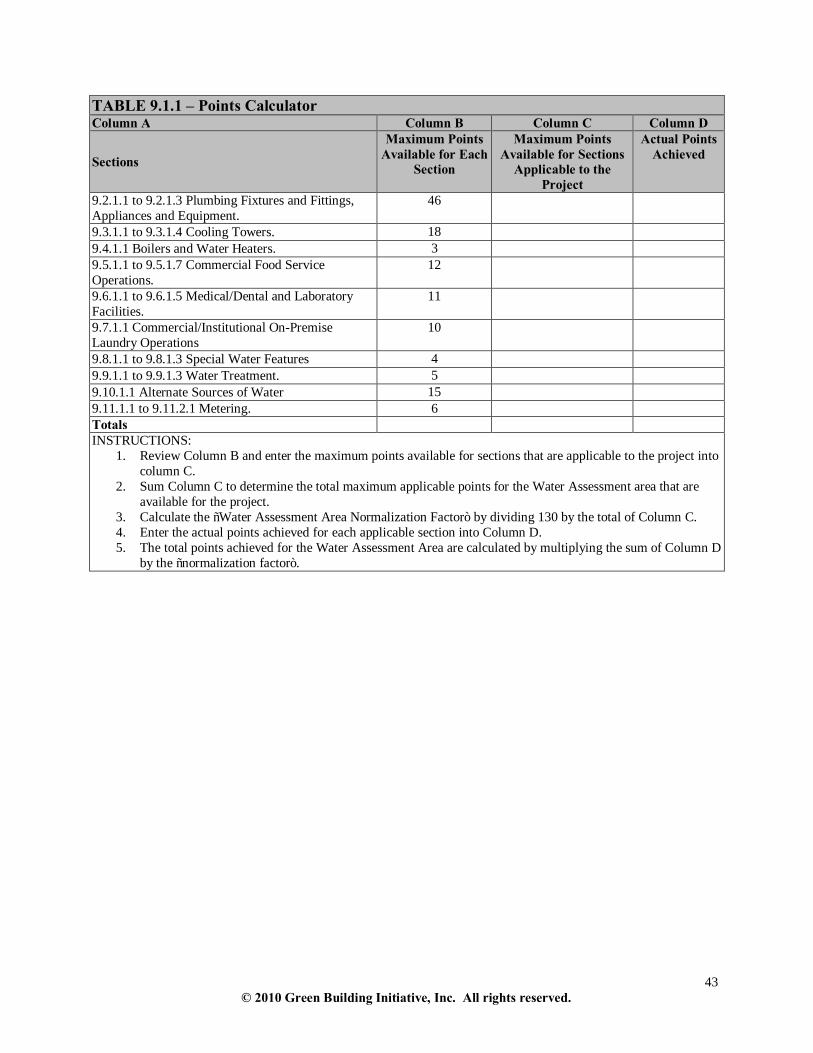
43 © 2010 Green Building Initiative, Inc. All rights reserved.
TABLE 9.1.1 – Points Calculator Column A Column B Column C Column D
Sections
Maximum Points Available for Each
Section
Maximum Points Available for Sections
Applicable to the Project
Actual Points Achieved
9.2.1.1 to 9.2.1.3 Plumbing Fixtures and Fittings, Appliances and Equipment.
46
9.3.1.1 to 9.3.1.4 Cooling Towers. 18 9.4.1.1 Boilers and Water Heaters. 3 9.5.1.1 to 9.5.1.7 Commercial Food Service Operations.
12
9.6.1.1 to 9.6.1.5 Medical/Dental and Laboratory Facilities.
11
9.7.1.1 Commercial/Institutional On-Premise Laundry Operations
10
9.8.1.1 to 9.8.1.3 Special Water Features 4 9.9.1.1 to 9.9.1.3 Water Treatment. 5 9.10.1.1 Alternate Sources of Water 15 9.11.1.1 to 9.11.2.1 Metering. 6 Totals INSTRUCTIONS:
1. Review Column B and enter the maximum points available for sections that are applicable to the project into column C.
2. Sum Column C to determine the total maximum applicable points for the Water Assessment area that are available for the project.
3. Calculate the “Water Assessment Area Normalization Factor” by dividing 130 by the total of Column C. 4. Enter the actual points achieved for each applicable section into Column D. 5. The total points achieved for the Water Assessment Area are calculated by multiplying the sum of Column D
by the “normalization factor”.

44 © 2010 Green Building Initiative, Inc. All rights reserved.
9.2 Plumbing Fixtures and Fittings, Appliances and Equipment (46 points) 9.2.1 Plumbing Fixtures and Fittings, Appliances and Equipment 9.2.1.1 The baseline water use, projected water use and percentage reduction in water use were calculated using Green Globes® Water Consumption Calculator, Version 1.3. The water consumption for the proposed building or project met or surpassed the requirements set forth in the US Energy Policy Act of 1992 (and subsequent revisions and additions up to 2005) by a minimum of 25%. Informational Reference (s): • Appendix M
Maximum = 24 points 25% - 30% = 6 points 31% - 35% = 12 points 36% - 40% = 18 points >40% = 24 points
9.2.1.2 All of the following plumbing fixtures and fittings were certified as being in compliance with the requirements and specifications of the U.S. EPA’s WaterSense Program: • Toilets (Watersense: maximum effective flush 1.28 gallons) • Urinals (Maximum effective flush volume 0.5 gallons) • Showerheads (Maximum effective flow rate 2.0 gallons per minute) • Residential Lavatory faucets (Watersense: maximum flow rate 1.5 gallons per
minute) • Residential kitchen faucets (Maximum flow rate 2.2 gallons per minute) • Non-residential lavatory faucets (Maximum flow rate 0.5 gallons per minute) For those plumbing fixtures and fittings not addressed by US EPA’s WaterSense Program requirements, consumption levels specified in the Green Globes® Water Consumption Calculator, Version 1.3 were used. Informational Reference (s): • Appendix M
18 points
9.2.1.3 The following appliances met the following water use maximums: • Residential clothes washers were EnergyStar labeled with a maximum water
factor of 23 L/m3 (6.0 gal/ft3) per full cycle. • Residential dishwashers were EnergyStar labeled with a maximum water factor of
22 L/m3 (5.8 gal/ft3) per full cycle.
Maximum = 4 points or n/a For each appliance, two points will be assigned to a maximum of four points.
9.2.2 Suggested Documentation • Construction documents; • Manufacturers specifications, cut sheets, and performance documentation for all plumbing fixtures, fittings and
appliances; • Results from the Green Globes® Water Consumption Calculator, Version 1.3.

45 © 2010 Green Building Initiative, Inc. All rights reserved.
9.3 Cooling Towers (18 points) 9.3. 1 Cooling Towers 9.3.1.1 Cooling towers for air conditioning systems achieved one of the following: • A minimum of 5 cycles of concentration for makeup waters having less than or
equal to 200 mg/L (200 ppm) total hardness as calcium carbonate or 3.5 cycles for makeup waters with more than 200 mg/L (200 ppm) total hardness as calcium carbonate.
OR • A minimum discharge conductivity of 1500 micromhos/cm, or maximum of 150
mg/L (150 ppm) of silica measured as silicon dioxide. OR • Exceeded the minimum water quality criteria as expressed above by 20% or more
(e.g. achieved 6 cycles, etc.)
Maximum = 6 points or n/a Exceeded the minimum water quality criteria by 20% or more = 6 points Achieved the minimum water quality criteria = 4 points n/a if no cooling towers
9.3.1.2Cooling tower(s) for air conditioning systems are covered by a water treatment program specifically designed for the site that at a minimum includes equipping towers with a make up meter, blowdown meter, and conductivity controllers.
6 points or n/a
9.3.1.3 One of the following strategies was used for cooling: • 20% of the annual heat rejected was dissipated with sensible (dry) cooling. • 21% to 50% of the annual heat rejected was dissipated with sensible (dry) cooling • 51% to 75% of the annual heat rejected was dissipated with sensible (dry) cooling • No wet cooling was used.
Maximum = 4 points or n/a 20% heat rejected = 1 point or n/a 21% -50% heat rejected = 2 points or n/a 51% -75% heat rejected = 3 points or n/a no wet cooling = 4 points or n/a
9.3.1.4 Cooling tower (s) were equipped with drift eliminators that achieved an efficiency of 0.001% or less for counterflow system or 0.005% or less for cross flow systems.
2 points or n/a
9.3.2 Suggested Documentation • Construction documents; • Manufacturer’s specifications, cut sheets, and performance documentation for cooling equipment, makeup
meter, blowdown meter, drift eliminators, conductivity controllers and wet/dry cooling towers. • Plumbing plans. 9.4 Boilers and Water Heaters (3 points) 9.4.1 Boilers and Water Heaters 9.4.1.1 Boilers and/or water heaters were installed with the following features: • Boilers and water heating systems of 50 bhp and above were installed with a
boiler feed makeup meter. • Boiler systems with over 50 bhp were installed with condensate return systems. • Boilers were fitted with conductivity controllers. • Steam boilers were installed with conductivity meters.
3 points or n/a

46 © 2010 Green Building Initiative, Inc. All rights reserved.
9.4.2 Suggested Documentation • Construction documents; • Manufacturer’s specifications, cut sheets, and performance documentation for boilers, water heating systems,
meters, controllers, and steam system plans; • Certificate from professional engineer for steam system. 9.5 Commercial Food Service Operations (12 points) 9.5.1 Commercial Food Service Equipment 9.5.1.1 Once-through water-cooled equipment was not installed. 3 points or n/a 9.5.1.2 Water-fed garbage disposals were not installed. 2 points or n/a 9.5.1.3 Installed ice machines met Energy Star requirements. 2 points or n/a 9.5.1.4 Installed combination ovens used no more than 15 L or 38 L (4 or 10 gal.) of water per hour.
Maximum = 2 points or n/a 15 L (4 gal.) of water = 1 point 38 L (10 gal.) of water = 2 points
9.5.1.5 Pre-rinse spray valves met or exceeded the requirements of the US Energy Policy Act of 2005 (and subsequent revisions and additions up to 2005).
1 point or n/a
9.5.1.6 All boilerless/connectionless food steamers use no more than 7.5 liters (2.0 gallons) per hour.
1 point or n/a
9.5.1.7 Installed dishwashers met Energy Star requirements at a minimum. 1 point or n/a 9.5.2 Suggested Documentation • Construction documents; • Manufacturer’s specifications, cut sheets, and performance documentation for pre-rinse spray valves, ice
machines, food steamers, dishwashers and combination ovens; • Plumbing plans. 9.6 Medical/Dental and Laboratory Facilities (11 Points)
9.6.1 Medical/Dental and Laboratory Equipment 9.6.1.1 Steam sterilizers were equipped with: • Mechanical vacuum equipment • Water tempering devices that only allow water to flow when the discharge of
condensate or hot water from the sterilizer exceeds 60°C (140°F).
Maximum = 4 points or n/a For each measure, 2 points will be assigned to a maximum of 4 points.
9.6.1.2 Laboratory or medical equipment used non-potable water for once through cooling. 3 points
9.6.1.3 Dry vacuum systems were installed for all medical/dental purposes. 2 points or n/a 9.6.1.4 One of the following technologies were used: • Digital imaging technology. OR • Film processors capable of processing x-ray films of more than 150 mm (5.9 in) in
length or width were equipped with water recycling units.
1 point
9.6.1.5 Installed wet scrubbers were equipped with water recirculation systems. 1 point or n/a

47 © 2010 Green Building Initiative, Inc. All rights reserved.
9.6.2 Suggested Documentation • Construction documents; • Manufacturer’s specifications, cut sheets, and performance documentation for steam sterilizers, laboratory or
medical equipment using non-potable water for once through cooling, water recycling units, and wet scrubbers; • Plumbing plans; • Description of alternate sources of water to be used. 9.7 Commercial/Institutional Laundry Operations (10 points)
9.7.1 Commercial/Institutional On-Premise Laundry Equipment 9.7.1.1 The water factor for installed clothes washers was 36 L/m3 (9.5 gal/ft3) per full cycle or lower.
Maximum = 10 points 28L/m3 (7.5 gal/ft3) or lower = 10 points 29L/m3 (7.6 gal/ft3) to 36 L/m3 (9.4 gal/ft3) = 4 points 36 L/m3 (9.4 gal/ft3) = 1 point
9.7.2 Suggested Documentation • Construction documents; • Manufacturer’s specifications, cut sheets, and performance documentation for clothes washers. 9.8 Special Water Features (4 points)
9.8.1 Special Water Features (e.g. swimming pools, spas, ornamental fountains, water playscapes)
9.8.1.1 Special water features filter and re-circulate water for reuse within the system. 1 point 9.8.1.2 Meters were installed for potable water makeup lines leading to all special water features.
1 point
9.8.1.3 Special water features use alternate sources of water for makeup water. 2 points
9.8.2 Suggested Documentation • Construction documents; • Manufacturer’s specifications, cut sheets, and performance documentation for all special water features and for
all meters; • Description of alternate sources of water to be used.

48 © 2010 Green Building Initiative, Inc. All rights reserved.
9.9 Water Treatment (5 points)
9.9.1 Water Treatment 9.9.1.1 Filtration systems were equipped with pressure drop guages that allow backwash to be based on pressure drop and not on timers.
2 points or n/a
9.9.1.2 One of the following reverse osmosis systems were used: • Reverse osmosis systems of less than 380 L (100 gal.) per day capacity reject no
more than 70% of the feed water volume. OR • Reverse osmosis systems producing more than 380 L (100 gal.) per day capacity
reject no more than 60% of the feed water volume.
2 points or n/a
9.9.1.3 Water softeners were equipped with recharge controls based on volume of water treated or hardness and not on timers.
1 point or n/a
9.9.2 Suggested Documentation • Construction documents; • Manufacturer’s specifications, cut sheets, and performance documentation for filtration systems, pressure drop
gauges, reverse osmosis systems, water softeners, and recharge controls. 9.10 Alternate Sources of Water (15 Points)
9.10.1 Alternate Sources of Water 9.10.1.1 Non-Potable water applications used alternate sources of water that included, but were not limited to, the following: • Air conditioner condensate • Cooling tower blowdown water • Foundation drain water • Graywater • Pass-through cooling water • Rainwater catchment and harvesting • Municipally recycled, treated wastewater (municipally reclaimed water) • Swimming pool filter backwash water • Industrial process water
Maximum = 15 points Percentage of potable water replaced by alternate sources. Alternate Sources 10% -20% = 2 points 21% - 30% = 4 points 31%-40 = 7 points 41%- 50% = 10 points 51%-60% = 13 points >60 = 15 points
9.10.2 Suggested Documentation • Construction documents; • Manufacturer’s specifications, cut sheets, and performance documentation; • Description of alternate source of water and implementation for non-potable water applications. 9.11 Metering (6 points)
9.11.1 Meter Data Management System 9.11.1.1 The following measures were implemented: • A Meter Data Management System was installed to electronically store water meter
and sub-meter data and create user reports showing calculated hourly, daily, monthly and annual water consumption for each meter or submeter.
• All building meters and sub-meters were configured to communicate water consumption data to a Meter Data Management System.
4 points
9.11.2 Makeup Meters 9.11.2.1 Chilled or hot water loops were equipped with makeup meters. 2 points or n/a

49 © 2010 Green Building Initiative, Inc. All rights reserved.
9.11.3 Suggested Documentation • Construction documents; • Manufacturer’s specifications, cut sheets, and performance documentation for the Meter Data Management
System and meters. 10. RESOURCES/MATERIALS 10. 1 Assemblies (Structural System and Envelope) This section does not apply to Furnishings, Finishes and Fit-outs or Mechanical, Electrical and Plumbing Systems
Assemblies - Performance Path A –(33 points) Assemblies - Prescriptive Path B (25 points)
10.1.1 Assemblies 10.1.2Materials Content Assemblies 10.1.3 Transportation of Harvested, Reclaimed, Salvaged, or Extracted Materials 10.1.4 Transportation of Processed or Manufactured Materials
BEGIN PERFORMANCE PATH A – Assemblies (33 points)
10.1.1 Assemblies—Performance Path 10.1.1.1 The Green Globes® LCA Credit Calculator for Building Assemblies, Version 1.9.43for Building Assemblies was used to evaluate building assemblies (structural system and envelope) in the conceptual design phase based on life cycle impacts. Informational Reference (s): • Appendix N - The Green Globes® LCA Credit Calculator for Building Assemblies,
Version 1.9.43
Maximum = 33 points Points are assigned by using the Green Globes LCA Credit Calculator for Building Assemblies, Version 1.9.43.
10.1.1.2 Suggested Documentation • Construction documents; • Manufacturer’s specifications, cut sheets, and performance documentation; • Input and results from the Green Globes LCA Credit Calculator for Building Assemblies, Version 1.9.43 END PERFORMANCE PATH A - Assemblies

50 © 2010 Green Building Initiative, Inc. All rights reserved.
BEGIN PRESCRIPTIVE PATH B– Assemblies (22 points)
10.1.2 Materials Content Assemblies 10.1.2.1 Recycled post-consumer or pre-consumer content materials accounted for 1% or more of building materials. Percentage = 100 x A÷B, where: A = Total cost or weight of recycled content materials B = Total cost or weight of all building materials Cost or weight must be used consistently. Informational Reference(s):
• EPA Resource Conservation Comprehensive Guidelines for Products.
Maximum = 8 points 1% - 3% = 1 point 4% - 6% = 2 points 7% -9% = 3 points 10% -12% = 4 points 13% - 15% = 5 points 16% - 17% = 6 points 18% - 19% = 7 points 20% or more = 8 points
10.1.2.2 Bio-based products accounted for 1% or more of materials used in the building. Percentage = 100 x A÷B, where : A = Total cost or weight of bio-based products B = Total cost or weight of all building materials Cost or weight must be used consistently. Wood-based products used to achieve these points must also meet the certification requirements of 10.3.2.1. For USDA-designated products, products meeting or exceeding USDA's bio-based content, criteria or qualifying as USDA “BioPreferredSM” were used.
Maximum = 7 points 1% - 3% = 1 point 4% - 6% = 2 points 7% -9% = 3 points 10% -12% = 4 points 13% - 15% = 5 points 16% - 19% = 6 points 20% or more = 7 points

51 © 2010 Green Building Initiative, Inc. All rights reserved.
10.1.3 Transportation of Harvested, Reclaimed Salvaged, or Extracted Materials 10.1.3.1 1% or more of materials and products used in the building were harvested, reclaimed, salvaged, or extracted: • Within a radius of 800 km (500 miles) of the project site; or • Shipped primarily by rail or water within a radius of 2400 km (1500 miles). For the purposes of this requirement, a regional product is one that has, at least 70% of the constituent materials of a product (by weight) that meet the distance requirements. If the extraction distance is a combination of rail and/or water and/or other method of transportation, then the calculated extracted combined distance (ECD) must be less than or equal to 1.0: ECD (in IP units) = EDR÷1500 + EDO÷500 ECD (in SI units) = EDR÷2400 + EDO÷800 EDR = extraction distance (distance between project and extraction, harvest, recovery or salvaging site) by rail or water in km (miles) EDO = extraction distance (distance between project and extraction, harvest, recovery or salvaging site) other than by rail or water in km (miles) Percentage = 100 x A÷B, where : A = Total cost or weight of regional materials B = Total cost or weight of all materials Cost or weight must be used consistently.
Maximum = 5 points 1% -5% = 1 point 6% -10% = 2 points 11% -15% = 3 points 16% - 20% = 4 points Over 20% = 5 points

52 © 2010 Green Building Initiative, Inc. All rights reserved.
10.1.4 Transportation of Processed or Manufactured Materials 10.1.4.1 1% or more of materials and products used in the building were processed or manufactured: • Within a radius of 800 km (500 miles) of the project site; or • Shipped primarily by rail or water within a radius of 2400 km (1500 miles). For the purposes of this requirement, a regional product is one that has at least 70% of the constituent materials of a product (by weight) that meet the distance requirements. If the distance from manufacturing is a combination of rail and/or water and/or other method of transportation, then the calculated extracted combined distance (MCD) must be less than or equal to 1.0: MCD (in IP units) = MDR÷1500 + MDO÷500 MCD (in SI units) = MDR÷2400 + MDO÷800 MDR = manufacture distance (distance between project and processing and/or manufacturing site) by rail or water in km (miles) MDO = manufacture (distance between project and processing and/or manufacturing site) other than by rail or water in km (miles) Percentage = 100 x A÷B, where: A = Total cost or weight of regional materials B = Total cost or weight of all materials Cost or weight must be used consistently.
Maximum = 5 points 1% -5% = 1 point 6% -10% = 2 points 11% -15% = 3 points 16% - 20% = 4 points Over 20% = 5 points
10.1.5 Suggested Documentation
• Construction documents; • Manufacturer’s specifications, cut sheets, and performance documentation; • List of recycled content materials and percentage calculations; • List of bio-based materials and percentage calculations; • List of harvested, reclaimed, salvaged or extracted materials and transportation distance calculations; • List of processed or manufactured materials and transportation distance calculations. END PRESCRIPTIVE PATH B – Assemblies 10. 2 Furnishings, Finishes and Fit-outs (17 points)
10.2.1 Furnishings, Finishes and Fit-outs— Life Cycle Assessment 10.2.1.1 A life cycle assessment tool was used to evaluate furnishings, finishes and fit-outs based on life cycle impacts. The life cycle assessment tool conforms to ISO 14044-06. Examples include: • BEES 4.0; • Third party peer reviewed life cycle assessments
Maximum = 4 points One point per product, up to a maximum of 4 points

53 © 2010 Green Building Initiative, Inc. All rights reserved.
10.2.2 Material Content - Furnishings, Finishes and Fit-outs 10.2.2.1 Recycled post-consumer or pre-consumer content materials accounted for 1% or more of furnishings, finishes and fit-outs. Percentage = 100 x A÷B, where: A = Total cost or weight of recycled content materials B = Total cost or weight of all furnishings, finishes and fit-outs materials Cost or weight must be used consistently.
Maximum = 5 points 1% - 4% = 1 point 5%-8% = 2 points 9%-12% = 3 points 13%-16% = 4 points 17% or more = 5 points
10.2.2.2 Bio-based products accounted for 1% or more of furnishings, finishes and fit-outs used in the building. Percentage = 100 x A÷B, where : A = Total cost or weight of bio-based products B = Total cost or weight of all building materials Cost or weight must be used consistently. For USDA-designated products, products meeting or exceeding USDA's bio-based content, criteria or qualifying as USDA “BioPreferredSM” were used. Wood-based products used to achieve these points must also meet the certification requirements of 10.3.2.1.
Maximum = 4 points 1% - 5% = 1 point 6% - 10% = 2 points 11% - 15% = 3 points 16% or more = 4 points Wood-based products must also meet 10.3.2.1 to obtain points.
10.2.3 Transportation of Harvested, Reclaimed, Salvaged, or Extracted Materials 10.2.3.1 1% or more of products used in the building were harvested, reclaimed, salvaged, or extracted: • Within a radius of 800 km (500 miles) of the project site; or • Shipped primarily by rail or water within a radius of 2400 km (1500 miles). For the purposes of this requirement, a regional product is one that has at least 70% of its constituent materials (by weight) that meet the distance requirements. If the extraction distance is a combination of rail and/or water and/or other method of transportation, then the calculated extracted combined distance (ECD) must be less than or equal to 1.0: ECD (in IP units) = EDR÷1500 + EDO÷500 ECD (in SI units) = EDR÷2400 + EDO÷800 EDR = extraction distance (distance between project and extraction, harvest, recovery or salvaging site) by rail or water in km (miles) EDO = extraction distance (distance between project and extraction, harvest, recovery or salvaging site) other than by rail or water in km (miles) Percentage = 100 x A÷B, where : A = Total cost or weight of regional materials B = Total cost or weight of all materials Cost or weight must be used consistently.
Maximum = 2 points 1% -19% = 1 points 20% or more = 2 points

54 © 2010 Green Building Initiative, Inc. All rights reserved.
10.2.4 Transportation of Processed or Manufactured Materials 10.2.4.1 1% or more of products used in the building were processed or manufactured: • Within a radius of 800 km (500 miles) of the project site, or • Shipped primarily by rail or water within a radius of 2400 km (1500 miles). For the purposes of this requirement, a regional product is one that has at least 70% of its constituent materials (by weight) that meet the distance requirements. If the distance from manufacturing is a combination of rail and/or water and/or other method of transportation, then the calculated extracted combined distance (MCD) must be less than or equal to 1.0: MCD (in IP units) = MDR÷1500 + MDO÷500 MCD (in SI units) = MDR÷2400 + MDO÷800 MDR = manufacture distance (distance between project and processing and/or manufacturing site) by rail or water in km (miles) MDO = manufacture (distance between project and processing and/or manufacturing site) other than by rail or water in km (miles) Percentage = 100 x A÷B, where: A = Total cost or weight of regional materials B = Total cost or weight of all materials Cost or weight must be used consistently.
Maximum = 2 points 1% -19% = 1 point 20% or more = 2 points
10.2.5 Suggested Documentation • Construction documents; • Manufacturer’s specifications, cut sheets, and performance documentation; • List of recycled content materials and percentage calculations; • List of bio-based materials and percentage calculations; • List of harvested, reclaimed, salvaged or extracted materials and transportation distance calculations; • List of processed or manufactured materials and transportation distance calculations. 10. 3 Other Material Properties (12 points)
10.3.1 Off-Site Salvaged Materials 10.3.1.1 Off-site salvaged materials accounted for 1% or more of the building materials. Percentage = 100 x A÷B, where: A = Cost or weight of off-site salvaged materials B = Total cost or weight of all building materials Cost or weight must be used consistently.
Maximum = 6 points 1% - 2% = 1 point 3% - 4% = 2 points 5% - 6% = 3 points 7% - 8% = 4 points 9% or more = 6 points

55 © 2010 Green Building Initiative, Inc. All rights reserved.
10.3.2 Certification of Wood-Based Products 10.3.2.1 10% or more of solid lumber, engineered wood, and other wood-based products used in the building was third-party certified by one of the following sustainable forestry programs:
• American Tree Farm System (ATFS) - 2004-2008 AFF Standard • Canadian Standards Association (CSA) - Z809 Sustainable Forest
Management Requirements and Guidance (SFM) 2002 • Forest Stewardship Council Standard (FSC) - FSC-STD-40-004 V2-0 • Sustainable Forestry Initiative program (SFI) - 2005-2009 Sustainable Forestry
Standard (SFIS) • Other programs recognized by the Programme for Endorsement of Forest
Certification (PEFC) - PEFC Council Technical Document – October 5, 2007 Percentage = 100 x A÷B, where A = Cost or weight of certified wood-based products B = Total cost or weight of all wood-based materials Cost or weight must be used consistently.
Maximum = 6 points 10% - 19% = 1 point 20% - 29% = 2 points 30% -39% = 3 points 40% -49% = 4 points 50% - 59% = 5 points 60% or more = 6 points
10.3.3 Suggested Documentation • Construction documents; • Manufacturer’s specifications, cut sheets, and performance documentation; • List of salvaged materials and percentage calculations; • Wood-based products certification documentation. 10.4 Reuse of Existing Structures (18 points)
10.4.1 Reuse of Building Façades 10.4.1.1 Excluding windows and doors, the new building re-used 10% or more of the existing building’s façade. Percentage = 100 x A÷B, where A = Area of retained façade B = Total existing building façade area
Maximum = 6 points or n/a 10% -20% = 1 point 21% -30% = 2 points 31% -40% = 3 points 41% - 50% = 4 points 51% - 60% = 5 points 61% - 75% = 6 points n/a if there is no existing building or where the existing building floor area is less than 92.m2 (1000 ft2)

56 © 2010 Green Building Initiative, Inc. All rights reserved.
10.4.2 Reuse of Structural Systems 10.4.2.1 The new building re-used 10% or more of existing building structural systems by gross building volume. Percentage = 100 x A÷B, where: A = Total volume of re-used existing structure B = Total volume of existing structure
Maximum = 6 points or n/a 10% - 25% = 1 point 26% - 40% = 2 points 41% - 65% = 3 points 66% - 80% = 4 points 81% - 95% = 5 points >95% = 6 points n/a if there is no existing building or where the existing building floor area is less than 92.9 m2 (1000 ft2)
10.4.3 Reuse of Non-Structural Elements 10.4.3.1 The new building reused 10% or more of existing non-structural elements by area. Percentage = 100 x A÷B, where : A = Total area of re-used existing non-structural elements B = Total area of existing non-structural elements Wall and roof areas are calculated as the projected area of the element (e.g. if an interior wall is re-used, the area is calculated as length x height of the wall).
Maximum = 6 points or n/a 10% - 25% = 1 point 26% - 40% = 2 points 41% - 65% = 3 points 66% - 80% = 4 points 81% - 95% = 5 points >95% = 6 points n/a if there is no existing building or where the existing building floor area is less than 92.9 m2 (1000 ft2).
10.4.4 Suggested Documentation • Construction documents; • Manufacturer’s specifications, cut sheets, and performance documentation; • Calculation for percentage of façade retained; • Calculation for the percentage of existing major structural systems re-used; • Calculations for area of existing non-structural elements re-used.

57 © 2010 Green Building Initiative, Inc. All rights reserved.
10.5 Reduction, Re-use and Recycling of Waste (9 points)
10.5.1 Demolition and Construction Waste 10.5.1.1 25% or more of demolition and construction waste was diverted from the landfill. Percentage = 100 x (1 - A÷B) where: A = Weight of waste sent to landfill B = Weight of total wastes Items that may be considered for recycling include but are not limited to cardboard, metal, brick, concrete, plastic, wood, acoustical ceiling tiles, glass, wallboard, carpet and insulation.
Maximum = 6 points Points are based on demolition and construction waste being diverted from landfill. 25% - 49% = 2 points 50% - 74% = 4 points >75% = 6 points
10.5.2 Reuse of Existing Materials for Site Development and Landscaping 10.5.2.1 The project reused existing materials for site development or landscaping (e.g., crushing concrete for aggregate base or drain rock, shredding vegetative materials for mulch, etc.)
1 point
10.5.3 Operational Waste 10.5.3.1 The building design addressed operations-related recyling programs through one or more of the following: • Built-in collection space in each kitchen; • Internally and externally sealed storage areas; • External aggregation/pick up space; • Composting area or composting system provided on-site.
2 points
10.5.4 Suggested Documentation • Construction documents; • Manufacturer’s specifications, cut sheets, and performance documentation; • Waste Minimization Plan; • Landscaping and Site Developments Plans showing incorporation of existing on-site materials; • Tipping records. 10.6 Resource Conservation through Design (14 points)

58 © 2010 Green Building Initiative, Inc. All rights reserved.
10.6.1 Building Service Life Plan 10.6.1.1 A building service life plan was prepared and included: • Service life estimates for structural, building envelope and hardscape materials that
need to be replaced during the life of the building, not including mechanical and electrical assemblies
• Expected service life for building assemblies and materials that require inspection and/or need to be replaced during the service life of the building, where service life was based on the following:
- temporary buildings < 10 years - medium-life buildings e.g. industrial and parking structures > 25 years - long life building types > 50 years
• Documentation of the project design service life, the basis for determination and the following details for each assembly or component used in the building:
- building assembly and material description - design service life in years - predicted service life in years - effects of failure - maintenance frequency and maintenance access
Informational Reference(s): • CSA S478-95 • ISO 15686 (series)
7 points
10.6.2 Materials and Raw Materials
10.6.2.1 An architect or design professional provided a letter documenting how the building design uses materials efficiently and/or minimizes the use of raw materials as compared with typical construction practices. The letter included specific measures, calculations, drawings and specifications describing how and where materials are used efficiently or raw material use is minimized. Informational Reference(s): • Appendix O
2 points
10.6.3 Multi-Functional Assemblies
10.6.3.1 Architect or design professional to provide letter documentation describing how the building design uses assemblies that perform multiple functions. The letter included specific examples, including applicable calculations, drawings or specifications. Informational Reference(s): • Appendix O
2 points
10.6.3.2 The building design plans facilitated demounting or dissassembling reusable materials without substantial damage to the materials or their surroundings. Informational Reference(s): • ASTM E1692-95 • CSA Z782-06
3 points
10.6.4 Suggested Documentation

59 © 2010 Green Building Initiative, Inc. All rights reserved.
• Letters and building models from architect or design professional; • Construction documents; • Formal Building Service Life Plan; • Manufacturer’s specifications, cut sheets, and performance documentation. 10.7 Building Envelope (30 points)
10.7.1 Roofing Membrane Assemblies and Systems 10.7.1.1 The following measures were implemented: • All low slope roofing membrane systems and interfaces were detailed and installed
in accordance with the manufacturer’s requirements and warranted by the manufacturer for the intended purpose. All low slope roofing membrane systems and interfaces were field inspected by a roofing system manufacturer’s technical personnel or RCI-certified third party roofing inspector in accordance with one of the following methods: - ARMA/NRCA – “Manual of Roof Inspection and Maintenance of Built-Up and
Modified Bitumen Roof Systems: A Guide for Building Owners.” - SPRI/NRCA – “Manual of Roof Inspection, Maintenance and Emergency
Repair for Existing Single-Ply Roofing Systems.” • All steep slope roofing systems and interfaces were detailed and installed in
accordance with the manufacturer’s requirements and warranted by the manufacturer for the intended purpose. A roofing system manufacturer’s technical personnel or RCI-certified third party roofing inspector performed a field inspection of the steep slope roofing in accordance with the “NRCA Roofing and Waterproofing Manual 5th Edition.”
5 points
10.7.2 Flashings 10.7.2.1 All building envelope flashings and sheet metal assemblies, including but not limited to those listed below, were detailed and installed in accordance with SMACNA’s “Architectural Sheet Metal Manual 2003.”
- Gutters and downspouts - Copings - Scuppers - Through wall flashing and associated end dams - Reglets and counterflashing - Equipment support flashing, openings flashing and roof edge flashings
• All proprietary products were installed in accordance with the manufacturer’s instructions and recommendations.
• A field inspection of all flashing assemblies was conducted in accordance with NIBS Guideline 3-06: Annex M.1 Construction & Industry Checklist M.1-4 for Flashing and Sheet Metal.
5 points

60 © 2010 Green Building Initiative, Inc. All rights reserved.
10.7.3 Roof and Wall Openings 10.7.3.1 All products for roof and wall openings were selected and configured to meet performance requirements of established Design Pressure, in accordance with AAMA/WDMA/CSA 101/I.S.2/A440-05. • Flashings at roof and wall openings were detailed and installed in accordance with
ASTM E2112–07. • A field inspection of all installations was conducted in accordance with NIBS
Guideline 3-06: Annex M.1 Construction & Industry Checklists M.1-7 for Windows and M.1-8 Skylights.
• A field test of water penetration was conducted with a minimum of 3 units per 100 of each type (doors, windows, skylights). These field tests were performed in accordance with the following: - ASTM E1105-93 - By applying same test pressures required to determine compliance with
specified requirements AAMA/WDMA/CSA 101/I.S.2/A440-05 field testing requirements.
- All detected failures were repaired and retested accordingly.
5 points
10.7.4 Foundation Systems 10.7.4.1 Conditioned spaces were constructed with slab-on-ground vapor retarders conforming to ASTM E1745 – 09. • All slabs on grade were placed directly over vapor retarders and capillary-break
basecourses. • A field inspection of all vapor retarder and waterproofing assemblies was
conducted in accordance with NIBS Guideline 3-06: Annex M.1 Construction & Industry Checklist M.1-1 for Waterproofing.
Informational Reference (s): • ACI 302.2R-06
2 points
10.7.4.2 Dampproofing was applied to all foundation walls in contact with grade, and the following measures were implemented: • 5% slope grade away from the building for at least 3.05 m (10 ft) • Means for roof drainage to be directed at least 0.9 m (3 ft) beyond the building
face. • A foundation drainage system was installed.
2 points
10.7.5 Below Grade Walls Slabs and Above Grade Horizontal Assemblies 10.7.5.1 Waterproofing membrane assemblies were installed at all below grade slabs and foundation/basement walls that were subject to hydrostatic pressures. • Waterproofing assemblies were installed in accordance with the manufacturer’s
requirements, and warranted by the manufacturer for the intended purpose. • A field inspection of installations was conducted in accordance with the following:
- NIBS Guideline 3-06: Annex M.1 Construction & Industry Checklist M.1-1 for Waterproofing.
- ASTM D5957 – 98 (05)
4 points Horizontal assemblies apply to assemblies of building materials used in horizontal applications such as parking garages, and plaza deck-type applications over habitable spaces or on elevated structures, but not intended for use on building roofing systems.

61 © 2010 Green Building Initiative, Inc. All rights reserved.
10.7.6 Exterior Wall Cladding Systems 10.7.6.1 The following exterior wall cladding systems were installed and field inspected in accordance with the following specifications: • Exterior Insulation Finishing Systems (EIFS) were installed as water-managed
systems in accordance with the manufacturers’ requirements. A field inspection was conducted in accordance with NIBS Guideline 3-06: Annex M.1 Construction & Industry Checklist M.1-2 for EIFS.
• Aluminum Framed Glazing systems were installed in accordance with the manufacturers requirements and warranted by the manufacturer for the intended purpose. A field inspection was conducted in accordance with NIBS Guideline 3-06: Annex M.1 Construction & Industry Checklist M.1-6 for Entrances and Storefronts and M 1-10 for Glazed Curtain Walls.
• Masonry Veneer Cladding systems were installed in accordance with industry technical notes and bulletins. A field inspection of Masonry Cladding was conducted in accordance with NIBS Guideline 3-06: Annex M.2 Example Construction Checklist for Building Envelope System for Brick.
• Architectural Precast Concrete Cladding Systems incorporated pressure equalized two stage joints between precast concrete panels and adjacent cladding assemblies.
• Joint Sealers were installed in accordance with NIBS Guideline 3-06: Annex M.2 Example Construction Checklist for Building Envelope System Joint Sealants. Checklist. A field inspection was conducted in accordance with NIBS Guideline 3-06: Annex M.1 Construction & Industry Checklist M.1-5 for Joint Sealers.
Informational Reference (s): • PCI Architectural Precast Two-Stage Joint Guidelines • Whole Building Design Guide
5 points
10.7.7 Rainscreen Wall Cladding 10.7.7.1 Exterior rainscreen wall cladding systems installed over framed walls were installed with the following:
- A primary and secondary line of defense - An air barrier - A means for incidental bulk water intrusion to escape the cladding system
assembly • Rainscreen cladding assemblies passed laboratory-testing requirements in
accordance with AAMA 508-07 for both pressure-equalized and non-pressure equalized cladding assemblies.
2 points
10.7.8 Suggested Documentation • Construction documents; • Manufacturer’s specifications, cut sheets, and performance documentation; • Field testing reports; • Manufacturers laboratory test results; • Plans for foundation systems, flashings, roof and wall openings, roofing, and cladding systems. 10.8 Air Barriers (6 points)
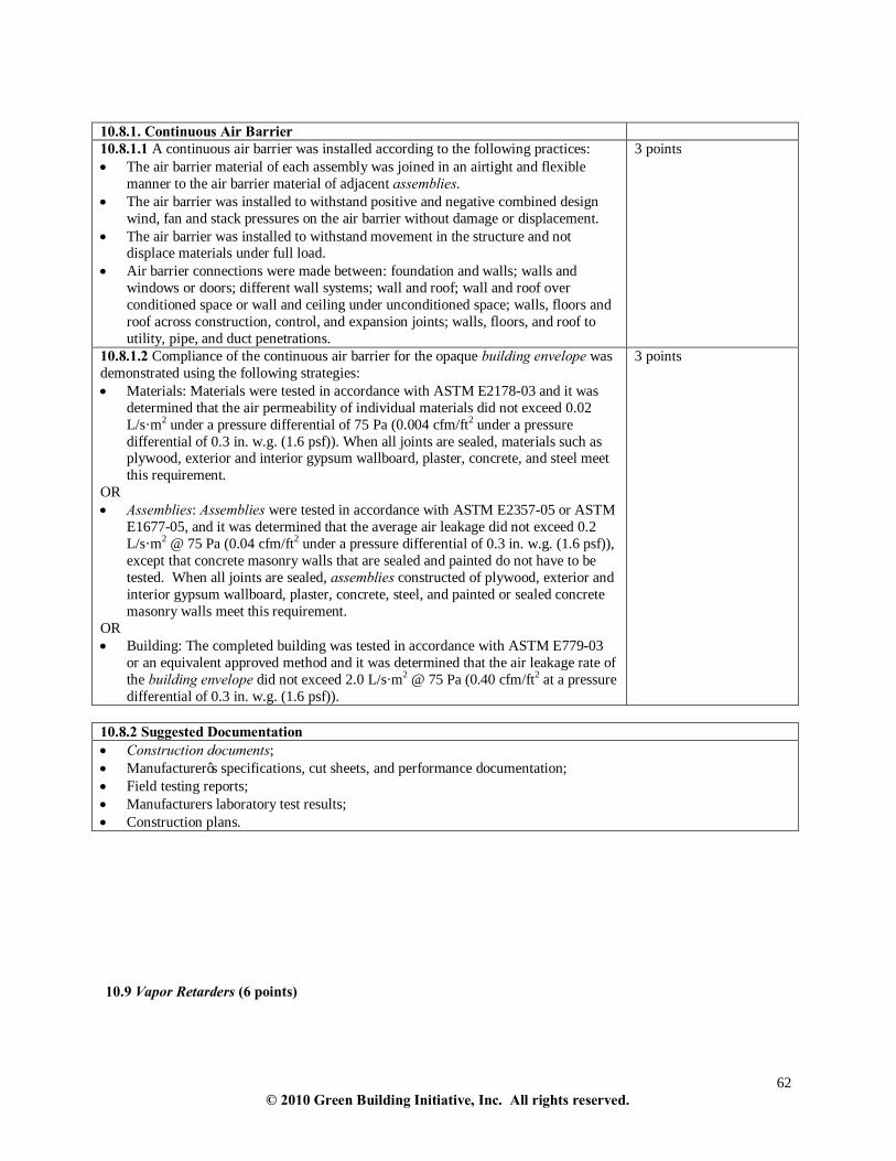
62 © 2010 Green Building Initiative, Inc. All rights reserved.
10.8.1. Continuous Air Barrier 10.8.1.1 A continuous air barrier was installed according to the following practices: • The air barrier material of each assembly was joined in an airtight and flexible
manner to the air barrier material of adjacent assemblies. • The air barrier was installed to withstand positive and negative combined design
wind, fan and stack pressures on the air barrier without damage or displacement. • The air barrier was installed to withstand movement in the structure and not
displace materials under full load. • Air barrier connections were made between: foundation and walls; walls and
windows or doors; different wall systems; wall and roof; wall and roof over conditioned space or wall and ceiling under unconditioned space; walls, floors and roof across construction, control, and expansion joints; walls, floors, and roof to utility, pipe, and duct penetrations.
3 points
10.8.1.2 Compliance of the continuous air barrier for the opaque building envelope was demonstrated using the following strategies: • Materials: Materials were tested in accordance with ASTM E2178-03 and it was
determined that the air permeability of individual materials did not exceed 0.02 L/s·m2 under a pressure differential of 75 Pa (0.004 cfm/ft2 under a pressure differential of 0.3 in. w.g. (1.6 psf)). When all joints are sealed, materials such as plywood, exterior and interior gypsum wallboard, plaster, concrete, and steel meet this requirement.
OR • Assemblies: Assemblies were tested in accordance with ASTM E2357-05 or ASTM
E1677-05, and it was determined that the average air leakage did not exceed 0.2 L/s·m2 @ 75 Pa (0.04 cfm/ft2 under a pressure differential of 0.3 in. w.g. (1.6 psf)), except that concrete masonry walls that are sealed and painted do not have to be tested. When all joints are sealed, assemblies constructed of plywood, exterior and interior gypsum wallboard, plaster, concrete, steel, and painted or sealed concrete masonry walls meet this requirement.
OR • Building: The completed building was tested in accordance with ASTM E779-03
or an equivalent approved method and it was determined that the air leakage rate of the building envelope did not exceed 2.0 L/s·m2 @ 75 Pa (0.40 cfm/ft2 at a pressure differential of 0.3 in. w.g. (1.6 psf)).
3 points
10.8.2 Suggested Documentation • Construction documents; • Manufacturer’s specifications, cut sheets, and performance documentation; • Field testing reports; • Manufacturers laboratory test results; • Construction plans. 10.9 Vapor Retarders (6 points)

63 © 2010 Green Building Initiative, Inc. All rights reserved.
10.9.1 Vapor Retarders 10.9.1.1 The interior side of framed walls in Climate Zones 5, 6, 7, 8 and Marine 4 were installed with a Class I or II vapor retarder that was in accordance with the International Energy Conservation Code 2007 Supplement or 2009 International Building Code Section 1405.3.
3 points
10.9.1.2. Crawl space walls located in unvented crawl spaces were insulated using the following strategy: • Insulation was permanently fastened to the wall and extended downward from the
floor to the finished grade level and then vertically and/or horizontally for at least an additional 60.9 cm (24 inches).
• Exposed earth in unvented crawl space foundations were covered with a continuous Class I vapor retarder that was installed using the following strategy: - All joints of the vapor retarder were overlapped by 15.2 cm (6 in) and were
sealed or taped. - The edges of the vapor retarder extended at least 15.2 cm (6 in) up the stem
wall and was attached to the stem wall.
3 points
10.9.2 Suggested Documentation • Construction documents; • Manufacturer’s specifications, cut sheets, and performance documentation; • Construction plans. 11. EMISSIONS 11.1 Heating Equipment (18 points) Points for Section 11.1 can be earned by following either Path A or Path B.
District Heating - Path A (18 points) Low and Ultra Low NOx/Low CO Boilers and Furnaces - Path B (18 points)
11.1.1 – District Heating (18 points) 11.1.2 - Ultra Low NOX / Low CO Boilers and Furnaces (10 points)
11.1.3 - Low NOX / Low CO Boilers and Furnaces (8 points)
BEGIN PATH A – District Heating (18 points)
11.1.1 District Heating 11.1.1.1 The district heating process did not use boilers and/or combustion processes for heat or water in the building.
18 points or n/a n/a if district heating is not used.
END PATH A – District Heating

64 © 2010 Green Building Initiative, Inc. All rights reserved.
BEGIN PATH B - Low and Ultra Low NOx/Low CO Boilers and Furnaces (18 points)
11.1.2 Ultra Low NOX / Low CO Boilers and Furnaces 11.1.2.1 Ultra low NOX / low CO boilers and furnaces have • NOX emissions that do not exceed 0.01 g/L (12 ppm) corrected to 3% O2, • CO emissions that do not exceed 0.05 g/L (50 ppm) corrected to 3% O2. Informational Reference (s): • Rule 1146.2: South Coast Air Quality Management District
10 points or n/a n/a if there are no boilers or furnaces.
11.1.3 Low NOX / Low CO Boilers and Furnaces 11.1.3.1 Low NOX / low CO boilers and furnaces have • NOx emissions that do not exceed 0.03 g/L (30 ppm) corrected to 3% O2, and • CO emissions do not exceed 0.1 g/L (100 ppm) corrected to 3% O2. Informational Reference (s): • Rule 1146: South Coast Air Quality Management District
8 points or n/a n/a if there are no boilers or furnaces.
11.1.4 Suggested Documentation • Construction documents; • Manufacturer’s specifications, cut sheets, and performance documentation for boilers and furnaces. END PATH B - Low and Ultra Low NOx/Low CO Boilers and Furnaces 11.2 Cooling Equipment (21 points) Section 11.2 should be marked as not applicable for those buildings that use district cooling.
11.2.1 Ozone-Depleting Potential (ODP) One of the following measures were used: • Refrigerants that have zero or “near zero” ozone depletion potential (ODP) were
used. OR • No refrigerants were used (not including portable cooling equipment, refrigerators,
temporary cooling equipment, or equipment with less than 0.5 kg (1 lb) of refrigerant).
Any HVAC refrigerants used in the building must comply with the US EPA's Significant New Alternative Policy (SNAP) Listing.
Maximum = 7 points ODP of Refrigerant ≤ .035 = 1 point ≤ .03 = 2 points ≤ .025 = 3 points ≤ .02 = 4 points ≤ .015 = 5 points ≤.01 = 6 points ≤ .005 = 7 points OR No refrigerants = 7 points
11.2.2 Global Warming Potential (GWP) One of the following measures were used: • Refrigerants that have low global warming potential (GWP100) were used. OR • No refrigerants were used (not including portable cooling equipment, refrigerators,
temporary cooling equipment, or equipment with less than 0.5 kg (1 lb) of refrigerant).
Any HVAC refrigerants used in the building must comply with the US EPA's Significant New Alternative Policy (SNAP) Listing.
Maximum = 7 points GWP100 of Refrigerant ≤ 1500 = 1 point ≤ 1100 = 2 points ≤ 900 = 3 points ≤ 700 = 4 points ≤ 500 = 5 points ≤ 300 = 6 points

65 © 2010 Green Building Initiative, Inc. All rights reserved.
≤ 100 = 7 points OR No refrigerants = 7 points
11.2.3 Leak Detection One of the following measures were used: • If refrigerants were used in cooling equipment, machinery rooms were equipped
with: − A leak detector capable of detecting leakage rates down to 2.0% per year for each
HVAC Product − An alarm capable of alerting the building operator to leakage thresholds. OR • No refrigerants were used (not including portable cooling equipment, refrigerators,
temporary cooling equipment, or equipment with less than 0.5 kg (1 lb) of refrigerant).
Any HVAC refrigerants used in the building must comply with the US EPA's Significant New Alternative Policy (SNAP) Listing. Refrigerant monitors, as required by ASHRAE Std. 15, are considered safety devices, and are not considered leak detection devices.
7 points
11.2.4 Suggested Documentation • Construction documents; • Manufacturer’s specifications, cut sheets, and performance documentation for cooling equipment, leak detection
equipment and alarms. 11.3 Storage of Janitorial Supplies (6 points)
11.3.1 Storage of Janitorial Supplies 11.3.1.1 Storage space provided for janitorial supplies was equipped with full-height floor-to-floor walls. Mechanical ventilation is used to exhaust to the exterior.
6 points or n/a n/a if janitorial supplies are not kept on site
11.3.2 Suggested Documentation • Construction documents; • Manufacturer’s specifications, cut sheets, and performance documentation.

66 © 2010 Green Building Initiative, Inc. All rights reserved.
12. INDOOR ENVIRONMENT 12.1 Ventilation Systems (39 points)
12.1.1 Ventilation Air Quantity 12.1.1.1 The following measures were implemented: • The quantity of ventilation air for the building was compliant with ASHRAE
Standard 62.1-07, the ICC 2009 International Mechanical Code, IAPMO 2009 Uniform Mechanical Code, or local codes or standards. • Construction documents indicated the ventilation schedule for all occupied
spaces. Informational Reference(s):
• ASHRAE 62.1-07: section 5.6 and 5.9. • ICC 2009 International Mechanical Code: section 605. • IAPMO 2009 Uniform Mechanical Code: Section 402.
10 points
12.1.2 Air Exchange 12.1.2.1 One of the following strategies was used for air exchange: • For mechanically ventilated buildings:
- The zone air distribution effectiveness Ez value was determined to be greater than or equal to 0.9 in all regularly occupied spaces, excluding circulation and transitional spaces.
AND/OR • For naturally ventilated buildings:
- All points within habitable spaces considered to be naturally ventilated are within 7.6 m (25 ft) of a permanent or operable wall, window or roof opening to the outdoors.
- The unobstructed area of the opening measured at least 4% of the net floor area that is being naturally ventilated.
- Where interior spaces were ventilated through adjoining rooms, the openings between the spaces were designed to have a minimum area of 8% of the net floor area of the interior room and were at least 2.3 m2 (25 ft2).
- All operable openings were installed to be readily accessible to building occupants.
Informational Reference(s): • ASHRAE 62.1-07: Section 5.1 • ASHRAE 62.1-07: Section 6.2
10 points

67 © 2010 Green Building Initiative, Inc. All rights reserved.
12.1.3 Ventilation Intakes and Exhausts 12.1.3.1 Ventilation systems were equipped with the following features: • Exhaust outlets and plumbing vent stacks were located at least 6.1 m (20 ft) away
from outdoor air intakes. • Outdoor air intakes were located at least 9.1 m (30 ft) away from sources of
pollution including dumpsters, parking areas, driveways, loading docks, natural gas lines, wet cooling towers, and garage doors/exhaust outlets.
• Outdoor air intakes were protected with 6.4 mm (0.3 in or smaller) mesh screens. • For each air handling system in single or multiple arrangements, filters were
compliant with ASHRAE 62.1-07. • Outdoor air inlets and outlets, including louvers and rain hoods, were sized
appropriately per ASHRAE 62.1-07. • Except in transfer air duct, all outdoor air, return air, and supply air systems were
equipped with rigid or flexible ductwork without the duct liner exposed to the air stream.
• Roof drainage slopes away from outdoor air intakes. Informational Reference(s):
• ASHRAE 62.1-07: section 5.6 and 5.9. • 2009 International Mechanical Code: section 605. • IAPMO Uniform Mechanical Code: Section 402.
8 points
12.1.4 CO2 Sensing and Ventilation Control Equipment 12.1.4.1 CO2 sensing and ventilation control equipment capable of active feedback and adjustment of ventilation in response to CO2 monitoring was installed in the following spaces: • High and variable occupancy spaces (e.g. meeting rooms, assembly areas, etc.);
and • Regularly occupied spaces.
6 points
12.1.5 Air Handling Equipment 12.1.5.1 The following measures were implemented: • Air handling equipment with a maximum supply volume greater than 17 m3 per
minute (600 ft3/min.) was equipped with filters with a Minimum Efficiency Reporting Value (MERV) of 13 (or equivalent) or higher.
OR • Terminal equipment with a maximum supply volume of 17 m3 per minute (600 ft3/
min.) or less (e.g. fan coils, distributed heat pumps, fan-powered variable air valve boxes) were equipped with: - The highest filtration level commercially available for the specific equipment
under consideration AND
- Main air handlers in terminal systems were equipped with MERV 13 filtration
5 points or n/a n/a if equipment provides no ventilation air and serves only a single zone.
12.1.6 Suggested Documentation • Construction documents and specifications; • Balancing reports for the ventilation systems; • Ventilation schedules; • Manufacturing specifications for ventilation systems, CO2 sensing and ventilation control equipment; • Ventilation air quantity design data; • Local ventilation codes or standards.

68 © 2010 Green Building Initiative, Inc. All rights reserved.
12.2. Source Control of Indoor Pollutants (34 points)
12.2.1 Volatile Organic Compounds 12.2.1.1 One or more of the following measures were implemented:
1. Materials identified in Tables 12.2.1-A, 12.2.1-B and 12.2.1-C that were used in the building met the applicable volatile organic compound (VOC) content OR the VOC emissions criteria in these tables using one of the test methods specified in the footnotes of the Tables. OR
2. Materials identified in Tables 12.2.1-A, 12.2.1-B and 12.2.1-C that were used in the building were demonstrated to have attained certification in one or more of the following programs:
- Green Label Plus (Carpet & Carpet Adhesive) – Carpet and Rug
Institute o Carpet Policy & Procedure Manual – GLCm_071809Ver0 o Adhesive Policy & Procedure Manual –
GLAm_062509Ver0 - Green Label (Carpet Cushion) – Carpet and Rug Institute - EcoLogoM (Paints & Adhesives) – Environmental Choice
o EcoLogo Standard for Adhesives – CCD-046 o EcoLogo Standard for Paints – Architectural Surface
Coatings CCD-047 o EcoLogo Standard for Recycled Paints – Architectural
Surface Coatings – Recycled Water-bourne CCD-048 - Green Seal (Paints & Adhesives)
o Green Seal Environmental Standard for Paints and Coatings, GS-11
o Green Seal Environmental Standard for Commercial Adhesives, GS-36
- FloorScore (Resilient Flooring) – Resilient Floor Covering Institute
o California Department of Health Services Standard Practice for the Testing Of Volatile Organic Emissions Sources Using Small Scale Environmental Chambers (CA/DHS/EHLB/R-174), JULY 15, 2004 with Addendum 2004-01
o SCS - EC10.2 -2007, Environmental Certification Program—Indoor Air Quality Performance. May, 2007
- GREENGUARD Children & Schools – GREENGUARD Environmental Institute
o “Program Manual For GREENGUARD Product Certification Programs” GG.PM.01 2009
o GREENGUARD Environmental Institute: Standard Method for Measuring and Evaluating Chemical Emissions From Building Materials, Finishes and Furnishings Using Dynamic Environmental Chambers (GGTM.P066.R8, 10/29/2008)
- Indoor Advantage Gold TM – Scientific Certification Systems o California Department of Health Services Standard Practice
for the Testing Of Volatile Organic Emissions Sources Using Small Scale Environmental Chambers (CA/DHS/EHLB/R-174, JULY 15, 2004 with Addendum
Maximum = 10 points Three points are awarded for materials in Table 12.2.1-A and three points are awarded in Table 12.2.1-B based on the following percentages: 0% – 40% = 1 points 41% – 80% = 2 points 81% –100% = 3 points Percentages shall be obtained by dividing the weight or quantity of any listed material (that meets the listed limit), by the weight or quantity of all of the same listed material. Two points are awarded for meeting floor / flooring covering emissions criteria in Table 12.2.1-C; all floor / floor covering products must meet emissions criteria (or awarded the applicable certification) to attain these points. Two points are awarded for interior fit out products emissions criteria listed in Table 12.2.1-C; all applicable interior fit out products must meet emissions criteria (or be awarded the applicable certification) to attain these points.

69 © 2010 Green Building Initiative, Inc. All rights reserved.
2004-01) o SCS - EC10.2 -2007, Environmental Certification
Program—Indoor Air Quality Performance, May, 2007 - Other technically equivalent voluntary certification programs
applicable to the product or material that meet or exceed the VOC content or VOC emissions criteria and use the applicable test methods referenced in the footnotes of the Tables 12.2.1-A, 12.2.1-B or 12.2.1-C.
In Table 12.2.1-A, percentages are determined by weight (grams / liter). Alternatively, a VOC budget can be used for adhesives and sealants covered in the table. Documentation must demonstrate the overall low-VOC performance has been attained, comparing between a baseline and design case. When the design or actual case is less than the baseline, the credit requirement is satisfied. The total VOC for the design case is determined by multiplying the volume of the product used by the threshold VOC levels for the baseline case and actual product VOC level for the design case. The baseline cannot be greater than the design case.” In Table 12.2.1-B, determining whether the VOC content of paint complies with this credit can be shown by either the use of MSDS sheets that shows that the VOCs for every paint used on the project meets the criteria OR by using a "VOC budget" approach. This calculation shows the total VOCs of the design and base cases, allowing evaluation and comparison for coating systems specified versus what is allowed under the credit requirements. The calculation indicates total VOCs in grams, and indicates whether the design case total lies within the base case requirement for total VOCs. In order for the calculation to work, the following information must be identified by the user: • Total square footage of area(s) to be painted. • VOC content of specified coating systems. • Coverage rates of coatings specified (from manufacturer’s data sheet). • Number of coats specified (primer and topcoats). • Sheen of each coating based on ASTM D523-08 – Standard Test Method for Specular Gloss.
Table 12.2.1–A: Adhesives and Sealants
Product Area Product Sub-area VOC Content¹ VOC Emissions Criteria2 Adhesives – Architectural Applications
Carpet / Carpet Pads 50 g/L To determine acceptability of the emission results, the estimated building concentrations are compared to ½ their corresponding chronic RELs. The two exceptions to this requirement are (1) formaldehyde for which the calculated building concentration shall not exceed ½ of the indoor REL of 33µg/m³ and (2) acetaldehyde in which the full chronic REL of 9µg/m³ shall not be exceeded.
Wood Flooring 100 g/L Rubber Flooring 60 g/L Subfloor 50 g/L Ceramic Tile 65 g/L VCT / Asphalt Tile 50 g/L Dry Wall Panel 50 g/L Cove Base 50 g/L Multipurpose Construction 70 g/L Structural Glazing 100 g/L Single Ply Roof Membrane 250 g/L
Adhesives – Substrates Metal to Metal 30 g/L Plastic Foams 50 g/L Porous Material (except wood) 50 g/L Wood 30 g/L Fiberglass 80 g/L
Adhesives – Specialty PVC Welding 510 g/L CPVC Welding 490 g/L ABS Welding 325 g/L Plastic Cement Welding 250 g/L

70 © 2010 Green Building Initiative, Inc. All rights reserved.
Adhesive Primer for Plastic 550 g/L Contact Adhesive 80 g/L Special Purpose Contact Adhesive 250 g/L
Sealants Architectural 250 g/L Non-membrane Roof 300 g/L
Single Ply Roof Membrane 450 g/L 1. VOC content is determined by subtracting water and exempt compounds and expressed as grams per liter, with no exception granted to
chlorinated chemical species. VOC limits must be in accordance with the South Coast Air Quality Management District (SCAQMD) Rule 1168 .
2. VOC emissions results are determined by either of the following test methods: “Standard Practice for the Testing of Volatile Organic Emissions from Various Sources Using Small-Scale Environmental Chambers CA/DHS/EHLB/R-174, July 14, 2004 with Addendum 2004-01, October 19, 2004" or “GREENGUARD Environmental Institute: Standard Method for Measuring and Evaluating Chemical Emissions From Building Materials, Finishes and Furnishings Using Dynamic Environmental Chambers (GGTM.P066.R8, 10/29/2008)" ”.
3. Indoor REL developed by the California Office of Environmental Health and Hazard Assessment (OEHHA).
Table 12.2.1-B: Walls Product Area Product Sub-area VOC Content¹ VOC Emissions Criteria2 Walls Paints - Interior Latex coatings flat 50 g/L To determine acceptability of the
emission results, the estimated building concentrations are compared to ½ their corresponding chronic RELs. The two exceptions to this requirement are (1) formaldehyde for which the calculated building concentration shall not exceed ½ of the indoor REL of 33µg/m³ and (2) acetaldehyde in which the full chronic REL of 9µg/m³ shall not be exceeded.
Paints - Interior Latex Coatings non flat 150 g/L
Untreated Masonry or Concrete Not applicable
1. VOC content is determined by subtracting water and exempt compounds and expressed as grams per liter, with no exception granted to chlorinated chemical species. For VOC content, a VOC is any organic compound that participates in atmospheric photochemical reactions as defined by the U.S. EPA in 40 CFR §51.100 (s) and has an initial boiling point lower than or equal to 280°C measured at standard conditions of temperature and pressure. The VOC concentration of the product shall not exceed those listed below in grams of VOC per liter of product as determined by ASTM D6886-03 “Standard Test Method for Speciation of the Volatile Organic Compounds (VOCs) in Low VOC Content Waterborne Air-Dry Coatings by Gas Chromatography”. Source of test method and criteria is Green Seal (GS-11).
2. VOC emissions results are determined by either of the following test methods: “Standard Practice for the Testing of Volatile Organic Emissions from Various Sources Using Small-Scale Environmental Chambers CA/DHS/EHLB/R-174, July 14, 2004 with Addendum 2004-01, October 19, 2004" or “GREENGUARD Environmental Institute: Standard Method for Measuring and Evaluating Chemical Emissions From Building Materials, Finishes and Furnishings Using Dynamic Environmental Chambers (GGTM.P066.R8, 10/29/2008)" ”.
3. Indoor REL developed by the California Office of Environmental Health and Hazard Assessment (OEHHA).
Table 12.2.1-C Floors and Other Interior Products
Product Area VOC Emissions Criteria1 Floors / Floor Coverings (including carpeting, resilient and other non-carpet flooring) and
To determine acceptability of the emission results, the estimated building concentrations are compared to ½ their corresponding chronic RELs. The two exceptions to this requirement are (1) formaldehyde for which the calculated building concentration shall not exceed ½ of the indoor REL of 33µg/m³ and (2) acetaldehyde in which the full chronic REL of 9µg/m³ shall not be exceeded.
Other Interior Products (including insulation, acoustical ceilings, and wall covering but excluding countertops, casework, cabinetry, and shelving.
1. VOC emissions results are determined by either of the following test methods: “Standard Practice for the Testing of Volatile Organic Emissions from Various Sources Using Small-Scale Environmental Chambers CA/DHS/EHLB/R-174, July 14, 2004 with Addendum 2004-01, October 19, 2004" or “GREENGUARD Environmental Institute: Standard Method for Measuring and Evaluating Chemical Emissions From Building Materials, Finishes and Furnishings Using Dynamic Environmental Chambers (GGTM.P066.R8, 10/29/2008)”.
2. Indoor REL developed by the California Office of Environmental Health and Hazard Assessment (OEHHA).
12.2.2 Leakage, Condensation and Humidity

71 © 2010 Green Building Initiative, Inc. All rights reserved.
12.2.2.1 The following measures were implemented: • HVAC systems and equipment were installed to control indoor dew point
temperature below that of the coldest surfaces in the space. • Materials and finishes resistant to mold growth (e.g. concrete, masonry, glass and
metals) were installed in kitchens, toilet rooms, pools, shower areas and similar spaces that generate high humidity.
• Floor drains were installed where equipment failures may cause plumbing leaks. Informational Reference (s): • ASHRAE 62.1-07:section 5.15 • ASHRAE Standard 160-09, Design Criteria for Moisture Design Analysis in
Buildings, September 2006
5 points
12.2.3 Access for HVAC Maintenance 12.2.3.1 For all portions of HVAC equipment requiring routine and periodic maintenance, the following measures were implemented: • Access to equipment and equipment sections is provided in accordance with the
ICC 2009 International Mechanical Code, IAPMO 2009 Uniform Mechanical Code, and the manufacturer published and/or suggested recommendations.
• Access locations and clearances, including clearances for full and partial equipment were indicated on design drawings.
• Distribution systems were installed in accordance with ASHRAE 62.1-07: section 5.14 and SMACNA’s “HVAC Duct Construction Standards: Metal and Flexible 3rd Edition 2005.”
• Architectural features related to access were installed in accordance with the International Building Code.®
• Full degree (minimum) swing for all hinged doors or fully removable access doors were indicated on design drawings for all access doors on all HVAC equipment
Informational Reference(s): • International Mechanical Code 2009 Section 13 • IAPMO Uniform Mechanical Code: section 304 • ASHRAE 62.1-07: section 5.14 • SMACNA’s “HVAC Duct Construction Standards: Metal and Flexible 3rd Edition
2005
4 points
12.2.4 Carbon Monoxide Monitoring 12.2.4.1 Carbon monoxide monitoring devices which provided an alarm (that were independent of, or in addition to, HVAC control/mitigation of carbon monoxide) were installed in enclosed parking garages and other areas with sources of combustion (e.g. boiler rooms).
3 points or n/a n/a if there are no parking garages or other areas with combustion sources.
12.2.5 Wet Cooling Towers 12.2.5.1 One of the following measures was implemented: • No wet cooling towers were installed. OR • Wet cooling towers were installed with drift eliminators and inlet air louvers
Maximum = 4 points or n/a 4 points = no wet cooling towers were installed 2 points = wet cooling towers were installed with drift eliminators and inlet

72 © 2010 Green Building Initiative, Inc. All rights reserved.
air louvers n/a if no wet cooling system
12.2.6 Domestic Hot Water Systems 12.2.6.1 The domestic hot water system was designed to maintain hot water storage at or above 55o C (131o F) or to be a tankless system. Informational Reference (s): • ASHRAE Guideline 12-00
2 points
12.2.7 Humidification and Dehumidification Systems 12.2.7.1 Drain pans for dehumidifying cooling coils were equipped with a 0.3 cm slope per meter (0.1 in slope per foot) in two directions toward the drain outlet, and were equipped with a drain seal and sufficient width to span the cooling coils Informational Reference (s): • ASHRAE 62.1-07 : section 5.11
2 points or n/a
12.2.7.2 Steam humidification systems or ultrasonic humidification systems were installed.
2 points or n/a
12.2.8 Ventilation and Physical Isolation for Specialized Activities 12.2.8.1 Separate ventilation and/or physical isolation was provided for specialized activities.
1 points or n/a n/a if there are no specialized ventilations
12.2.8.2 Where separate ventilation systems were installed for specialized activities, they were maintained at a negative pressure of at least 5.0 Pascals (0.02 in of water gauge) on average with respect to adjacent spaces (with doors closed).
1 points or n/a n/a if there are no separate ventilation systems
12.2.9 Suggested Documentation • Construction documents; • Manufacturer’s specifications, cut sheets, and performance documentation for HVAC systems, humidification /
dehumidification systems, CO2 monitoring devices, wet cooling towers and domestic hot water systems list of mold resistant materials;
• Documentation demonstrating compliance with ASHRAE 62.1-07: section 5.14, SMACNA’s “HVAC Duct Construction Standards: Metal and Flexible 3rd Edition 2005,” and ICC’s “International Building Code®”;
• Materials Safety Data Sheets or proof of certification for low-VOC products or materials. 12.3 Source Control (6 points)
12.3.1 Pest and Contamination Control 12.3.1.1 The following integrated pest management strategies were used: • Outdoor air inlets were equipped with insect screens of 18x14 mesh for plenum
systems feeding multiple air handlers. • Structural and mechanical openings were fitted with permanent protection (e.g.,
screens, sealants, etc.). • Advertising signs and other assemblies affixed to the building façade are designed
and constructed in a way that reduces bird habitation and penetrations in the façade are sealed to prevent entry.
• Mullions and ledges were less than 2.5 cm (1 in) deep to discourage bird roostings.
2 points
12.3.1.2 A sealed storage area for food/kitchen solid waste and recycling was provided. 2 points

73 © 2010 Green Building Initiative, Inc. All rights reserved.
12.3.2 Radon Entry and Control 12.3.2.1 An owner or owner’s representative provided a letter addressing: New Construction: • Assessment of site specific radon potential; • Installation of passive or active radon mitigation system or justification for no
mitigation.
Major Renovation: • How testing for radon was conducted (existing structure); • Assessment of site specific radon potential (addition to structure); • Installation of passive or active radon mitigation system, other means of
mitigation, or justification for no mitigation. Informational References:
• EPA Map of Radon Zones • Radon Prevention in the Design and Construction of Schools and Other Large
Buildings. United States Environmental Protection Agency EPA/625/R-92/016, June 1994
• ASTM E2121-08 Standard Practice for Installing Radon Mitigation Systems in Existing Low-Rise Residential Buildings
• ASTM E1465-08: Standard Practice for Radon Control Options for the Design and Construction of New Low-Rise Residential Buildings 2007
• Building Radon Out: A Step-by-Step Guide on How to Build Radon-Resistant Homes. United States Environmental Protection Agency EPA 402-K-01-002, April 2001
• Large Buildings Characteristics as Related to Radon Resistance: A Literature Review. United States National Risk Management; Environmental Protection Agency Research Laboratory; Research Triangle Park, NC 27711; Research and Development EPA/600/SR-97/051 July 1997
2 points
12.3.3 Suggested Documentation • Construction documents; • Manufacturer’s specifications, cut sheets, and performance documentation; • Description of radon assessment and justification for mitigation system if applicable; • Description of pest management strategies.

74 © 2010 Green Building Initiative, Inc. All rights reserved.
12.4 Lighting Design and Integration of Lighting Systems (39 points)
12.4.1 Daylighting 12.4.1.1 Primary occupied spaces were designed to receive indirect minimum daylight illumination levels of 25 footcandles measured horizontally at work surface height between 12 noon and 2 PM on the vernal or autumnal equinox except where daylighting would compromise the function for which the spaces were designed (e.g. spaces that, due to function, require darkness, such as theatres, media rooms, projection rooms, and conference rooms in which projected presentations are given where no other means of daylighting control has been provided)." Informational Reference(s):
• ASHRAE Advanced Engineering Design Guides
Maximum = 11 points or n/a Points are assigned based on the percentage of occupied area with minimum daylight illumination levels of 25 footcandles versus the total occupied area. 10% - 30% = 3 points 31% - 59% = 7points >60% = 11 points
12.4.1.2 Interior spaces were designed to have views to the outside or to atria with a maximum distance of approximately 7.6 m (25 ft) or less from task area to window.
Maximum = 9 points or n/a Points are assigned based on the percentage of number of task areas that have a view to the building exterior versus the total number of task areas in the building. 10% - 30% = 3 points 31% - 59% = 6 points >60% = 9 points
12.4.1.3 The following measures were implemented: • Shading devices were installed for southern, western and eastern exposures. • Shading devices were employed to eliminate direct sunlight from reaching task
areas. • In occupied spaces having exterior windows, photo-responsive controls were
integrated to maintain consistent light levels using both daylighting and artificial lighting.
Maximum = 6 points For each measure implemented, two points will be assigned to a maximum of six points.

75 © 2010 Green Building Initiative, Inc. All rights reserved.
12.4.2 Lighting Design
12.4.2.1 Primary occupied spaces were equipped with lighting levels as recommended in the most recent IESNA Lighting Handbook 9th Edition, for the types of major tasks anticipated in the various building spaces.
7 points
12.4.2.2 To address reflective glare from electrical lighting on Visual Display Terminal’s (VDT’s), the following measures were employed: • Walls were provided with adequate luminance to meet a 3:1 task to far surround
luminance ratio. • For direct lighting, the average luminance did not exceed the following values for
given luminaire angles: - 850 cd/m2 (248.1 fL) at 65° from the vertical - 350 cd/m2 (102.2 fL) at 75° from the vertical - 175 cd/m2 (51.1 fL) at 85° from the vertical
• For indirect lighting, ceiling uniformity was lower than 8:1 (Max: Min) between rows of luminaires. For maximum ceiling luminance not exceeding 425cd/m2
(124.1 fL), the Max: Min ratio did not apply. OR • Spaces were designed such that source/task eye geometry did not require IESNA
Standard VDT compliant luminaires.
Maximum = 6 points or n/a For each measure implemented, two points will be assigned to a maximum of six points. OR Six points for alternate.
12.4.3 Suggested Documentation • Construction documents; • Manufacturer’s specifications, cut sheets, and performance documentation; • Percentages and calculations for occupied areas with daylight illumination levels; • Percentages and calculations for views to building exterior or atria; • Percentages and calculations for primary occupied spaces with IESNA recommended task lighting levels; • Specifications for solar shading devices and luminaries; • Lighting plans.

76 © 2010 Green Building Initiative, Inc. All rights reserved.
12.5 Thermal Comfort (20 points)
12.5.1 Thermal Control Zones 12.5.1.1 One of the following thermal comfort strategies were used: Maximum = 10 points Office Buildings A: Thermal control zones were designed to be less than 92.9 m2 (1000 ft2) for open areas or 111.5 m2 (1200 ft2) for single rooms (e.g. office or conference room). OR B: Thermal control zones were designed to be less than 46.5 m2 (500 ft2) for open areas or 69.7 m2 (750 ft2) for a single room or workstation. For mixed-use buildings, score each functional area and prorate score by floor area.
A: 5 points or n/a OR B: 10 points or n/a n/a if not an office building
Educational Buildings (Classrooms) Classrooms were designed to be single thermal control zones under 139.4 m2 (1500 ft2). AND Thermal control zones were designed to be less than 92.9 m2 (1000 ft2) for all other educational areas (excluding gyms and assemblies). For mixed-use buildings, score each functional area and prorate score by floor area.
10 points or n/a For each measure implemented, five points will be assigned to a maximum of ten points. n/a if not an educational building.
Healthcare Buildings (Patient areas) A: Thermal control zones were designed to be less than 92.9 m2 (1000 ft2). OR B: Thermal control zones were designed to be less than 46.5 m2 (500 ft2). For mixed-use buildings, score each functional area and prorate score by floor area.
A: 5 points or n/a OR B: 10 points or n/a\ n/a if not a healthcare building
Mercantile Buildings A: Thermal control zones were designed to be less than 464.5 m2 (5000 ft2). OR B: Thermal control zones were designed to be less than 185.8 m2 (2000 ft2). For mixed-use buildings, score each functional area and prorate score by floor area.
A: 5 points or n/a OR B:10 points or n/a n/a if not a mercantile building
Other Building Types Documentation was provided demonstrating how thermal control zones were designed to address thermal comfort. For mixed-use buildings, score each functional area and prorate score by floor area.
10 points or n/a n/a if not ‘other building type.’
12.5.2 Thermal Comfort Design 12.5.2.1 The building design was determined to be in conformance with ANSI/ASHRAE Standard 55-04.
10 points
12.5.3 Suggested Documentation • Construction documents; • Manufacturer’s specifications, cut sheets, and performance documentation; • Documentation demonstrating compliance with ANSI/ASHRAE Standard 55-04. 12.6 Acoustic Comfort (22 points)
12.6.1 Acoustic Comfort Design 12.6.1.1 Acoustic design strategies for specific interior sound control performance targets were implemented as follows: • Toilets were located remotely from acoustically separated areas;
4 points

77 © 2010 Green Building Initiative, Inc. All rights reserved.
• Acoustically separated areas were located away from noise producing areas such as dance studios, music rooms, cafeterias, indoor swimming pools, mechanical rooms, and gymnasia;
• Entry doors to rooms opposite each other on the same corridor were staggered; • Through-wall penetrations comply with Annex B of ANSI S12.60-2006; • Walls separating acoustically separated areas from other areas were constructed
full height to underside of the next floor above or the roof deck; • Walls separating quiet areas from other areas have all joints and penetrations
sealedwith acoustical sealant; • Areas with high floor impact activities (dance studios, shops, gymnasia, etc.) were
not located above acoustically separated areas; • In open office areas, 60 inch high (minimum) open office furniture and/or high
performance ceiling tile 180 Articulation Class (AC) minimum is specified, and a sound masking system, based on an acoustical design in which the performance mimima for spatial uniformity, temporal uniformity, spectrum shape, and sound level are specified, and confirmed in accordance with ASTM E1573-02.
Informational Reference(s): • ASHRAE Handbook – HVAC Applications (Chapter 47) • ANSI S12-2-2002 • ASTM E1374 -06 12.6.1.2 Minimum Sound Transmission Class (STC) ratings of floor/ceiling assemblies, walls and doors between acoustically separated areas (learning spaces) and adjacent spaces are as follows: • If adjacent space is a Corridor, Stair, Office or Conference Room: STC-45; • If adjacent space is a quiet area, speech clinic, health clinic, classroom, or an exterior wall: STC-50; • Doors to quiet areas: STC-50; • Doors to Music Rooms, Cafeterias, natatoria, Gymnasia: STC-40; • Exterior windows: STC-35.
2 points
12.6.1.3 Impact Insulation Class (IIC) of all floor-ceiling assemblies have a minimum rating of IIC-50.
2 points
12.6.1.4 Calculations were done using RT60 to determine that Reverberation Time (RT) in quiet areas and all other areas where speech intelligibility is important does not exceed: • 0.6 seconds in spaces less that 10,000 cu. ft. in volume; • 0.7 seconds in spaces larger that 10,000 cu. ft. but less than 20,000 cu. ft. in
volume; • compliance with Annex C of ANSI S12.60 – 2006 in spaces larger than 20,000 cu.
ft. in volume.
2 points
12.6.2 Mechanical, Plumbing and Electrical Systems 12.6.2.1 Measures were implemented to achieve reduced background sound level performance associated with mechanical systems as follows: • Sound power levels for each HVAC unit were calculated based on fan motor
power, fan capacity, static pressure, and discharged air volume to assure that, based on a one-hour steady state static background noise level, air-borne sound power levels from HVAC units do not exceed the following Room Criteria in listed spaces when HVAC units are in operation:
• Spaces are designed such that room background noise using the Room Criteria (RC) rating comply with ASHRAE Systems Application Handbook-2007, Chapter 47, Table 42.
Informational Reference (s):
4 points or n/a n/a for the speech intelligibility index for multi-unit residential buildings (MURBs).

78 © 2010 Green Building Initiative, Inc. All rights reserved.
• ASA/ INCE/ NCAC Interim Sound and Vibration Design Guidelines for Hospital and Healthcare Facilities
• CHPS –Collaborative for High Performance Schools • HUD Guide to Airborne, Impact and Structure Borne Noise • WBDG – Federal Green Construction Guide for Specifiers: 01 57 19.12 (01353)
Noise and Acoustic Management • WBDG – DG 1110-3-122 Design Guide for Interiors, 1997. • ASTM E989-06 12.6.2.2 The following measures were implemented to minimize air-borne noise from the HVAC system: • Duct transitions were spread out and graduated to minimize generation of
turbulence and air flow separations. • Secondary attenuators were placed immediately downstream of duct fittings that
would otherwise generate noise. • Air flow velocities in low pressure ductwork did not exceed:
-In main duct trunk lines: 4.5 m/s (900 f/m) -In branch ducts: 3.5 m/s (700 f/m) -In final run outs: 2.0 m/s (400 f/m) -In main vertical ducts in shafts: 6 m/s (1200 f/m)
• Where significant cross talk paths exist between two habitable spaces, sound attenuators and/or silencers were used or ducts are designed in a "Z" configuration.
• HVAC grilles and diffusers were selected that comply with ANSI S12.60 - 2006 Informational Reference (s): • ASTM E1332-03 • ASTM E90-04 • ASTM E1686-03 • ASTM E413-04 • ASTM E966-04 • ANSI S12-2-99 • ASA/ INCE/ NCAC Interim Sound and Vibration Design Guidelines for Hospital
and Healthcare Facilities • ASTM E1374-06 • ANSI S 12.60-2002 • ASTM E336-07
2 points
12.6.2.3 The following measures were implemented to minimize structure-borne noise from the HVAC system: • Fans and other powered HVAC equipment were acoustically separated from the
structure using vibration isolators. • Ducts were supported on resilient mounts to isolate them from the structural
system, and ducts are isolated using resilient material where they pass through walls.
2 points
12.6.2.4 Measures were implemented to mitigate noise from the plumbing system: • Piping was not run above quiet areas and learning spaces with the exception of
sprinklers and radiant heating systems. • Waste water piping noise is mitigated using cast iron pipe or with acoustic
insulation above quiet areas and learning spaces. • Water hammer arrester was used.
2 points
12.6.2.5 The following measures were implemented to minimize noise from the electrical system: • Low-noise ballasts are specified to be installed in quiet areas and all other areas
where speech intelligibility is important. • Noise from light fixtures and other electrical fixtures does not exceed values
2 points

79 © 2010 Green Building Initiative, Inc. All rights reserved.
indicated in ANSI S12.60 – 2006.
12.6.4 Suggested Documentation • Construction documents; • Manufacturer’s specifications, cut sheets and performance documentation; • Sound level measurements taken at the property line; • Description of acoustic design strategies and all design targets; • FIIC value for flooring assemblies; • Acoustic mitigation measures for mechanical equipment and plumbing systems; • Specification which includes Annex E of ANSI S12.60 – 2006; • Test Report indicating compliance with ANSI S12.60 – 2006. Note that the Foreword and Appendices are informative only and do not contain mandatory requirements necessary for conformance to this Standard. As such, they may contain material that has not been subjected to public review or a consensus process. Reference documents cited within the Standard are mandatory unless they are clearly identified as being informational references. Referenced documents are only to be applied within the context for which they are cited. The applicable version of any referenced documents, codes, standards, programs, or testing methods shall be identified by the version number or date. In cases where no version or date is provided, the applicable version of the document, code, standard, program, or testing method shall be the one in effect on October 2, 2009. 13. REFERENCES AND GUIDELINES Air-Conditioning, Heating and Refrigeration Institute (AHRI) AHRI 885-2008, Procedure for Estimating Occupied Space Sound Levels in the Application of Air Terminals and Air Outlets. American Architectural Manufacturers Association (AAMA) AAMA/CSA/WDMA 101/I.S.2/A440-2005, Specifications for Windows, Doors and Unit Skylights Field Testing Requirements. AAMA 508-2007, Voluntary Test Method and Specification for Pressure Equalized Rainscreen Wall Cladding Systems for both Pressure Equalized and Non-pressure Equalized Cladding Assemblies. American Association of Textile Chemists and Colorists (AATC) AATCC Method 30-2004, Antifungal Activity, Assessment on Textile Materials: Mildew and Rot Resistance of Textile Materials. AATCC Method 100-2004, Antibacterial Finishes on Textile Materials: Assessment of. AATCC 174-2007, Antimicrobial Activity Assessment of Carpets Parts II and III . American Concrete Institute (ACI) ACI 302.2R-06, Guide for Concrete Slabs that Receive Moisture-Sensitive Flooring Materials American Forest Foundation (AFF) AFF Standard-2004-2008, the American Tree Farm System (ATFS): Standards of Sustainability for Forest Certification: Including Performance Measures and Field Indicators. Associated General Contractors of America (AGC) Constructing an Environmental Management System: Guidelines and Templates for Contractors.

80 © 2010 Green Building Initiative, Inc. All rights reserved.
American National Standards Institute (ANSI) ANSI/SMACNA American National Standard 006-2006, HVAC Duct Construction Standards – Metal and Flexible. ANSI/ASHRAE Standard 55-2004, Thermal Environmental Conditions for Human Occupancy. ANSI/ASHRAE/IESNA Standard 90.1-2007, Energy Standard for Buildings Except Low-Rise Residential Buildings: section 6.5.6.1, Appendix G. ANSI S12.2-1999, Criteria for Evaluating Room Noise. ANSI S12.60-2002 American National Standard Acoustical Performance Criteria, Design Requirements, and Guidelines for Schools American Society of Heating, Refrigerating and Air-Conditioning Engineers (ASHRAE) ASHRAE Standard 62.1-2007: sections 5.1, 5.6, 5.6.2 to 5.6.5, 5.9, 5.11, 5.14, 5.15, 6.2, and Appendix A. ASHRAE/NIBS Guideline 0-2005, The Commissioning Process: ANNEX I, ANNEX J, ANNEX K, ANNEX L, Article 5, Article 6, Article 7, Article 7.2.14. ASHRAE 62.1-2007, Ventilation for Acceptable Indoor Air Quality: sections 5.1, 5.11, 5.15. and 6.2. ASHRAE Proposed 160, September 2006, Design Criteria for Moisture Control in Buildings. ASHRAE Guideline 12-2000, Minimizing the Risk of Legionellosis Associated with Building Water Systems. ASHRAE 1322-RP, Productivity and Perception Based Evaluation of Indoor Noise Criteria. The ASHRAE Handbook – HVAC Applications: Chapter 27. Asphalt Roofing Manufacturers Association (ARMA) ARMA/NRCA, Manual of Roof Inspection and Maintenance of Built-Up and Modified Bitumen Roof Systems: A Guide for Building Owners. Acoustical Society of America (ASA)/ Institute of Noise Control Engineering (INCE)/ National Council of Acoustical Consultants (NCAC) ASA/ INCE/ NCAC Interim Sound and Vibration Design Guidelines for Hospital and Healthcare Facilities, 2006. ASTM International (ASTM) ASTM D6329-1998 (2003), Standard Guide for Developing Methodology for Evaluating the Ability of Indoor Materials to Support Microbial Growth Using Static Environmental Chambers. ASTM D5957-1998 (2005), Standard Guide for Flood Testing Horizontal Waterproofing Installations. ASTM D3273-2000 (2005), Standard Test Method for Resistance to Growth of Mold on the Surface of Interior Coatings in an Environmental Chamber. ASTM E989-06 Standard Classification for Determination of Impact Insulation Class (IIC) ASTM E966-04 Standard Guide for Field Measurements of Airborne Sound Insulation of Building Facades and Facade Elements ASTM E 90-2004, Standard Test Method for Laboratory Measurement of Airborne Sound Transmission Loss of Building Partitions and Elements.

81 © 2010 Green Building Initiative, Inc. All rights reserved.
ASTM E779-2003, Standard Test Method for Determining Air Leakage Rate by Fan Pressurization. ASTM E547-1997, Windows, Skylights, Doors, and Curtain Walls by Uniform or Cyclic Static Air Pressure Difference. ASTM E413-04 Classification for Rating Sound Insulation ASTM E336-07 Standard Test Method for Measurement of Airborne Sound Attenuation between Rooms in Buildings ASTM E2121-08 Standard Practice for Installing Radon Mitigation Systems in Existing Low-Rise Residential Buildings ASTM E1465-08 Standard Practice for Radon Control Options for the Design and Construction of New Low-Rise Residential Buildings 2007 ASTM E2400-06 Standard Guide for Selection, Installation, and Maintenance of Plants for Green Roof Systems ASTM E2399-08 Standard Test Method for Maximum Media Density for Dead Load Analysis of Green Roof Systems. See Proposed Revision: WK17400 ASTM E2357-2005, Standard Test Method for Determining Air Leakage of Air Barrier Assemblies. ASTM E2178-2003, Standard Test Method for Air Permeance of Building Materials. ASTM E2112 –2007, Standard Practice for Installation of Exterior Windows, Doors and Skylights. ASTM E1745-09-Standard Specification for Water Vapor Retarders Used in Contact with Soil or Granular Fill under Concrete Slabs. ASTM E1692-1995 (2005), Standard Classification for Serviceability of an Office Facility for Change and Churn by Occupants. ASTM E 1686-2003, Standard Guide for Selection of Environmental Noise Measurements and Criteria. ASTM E1677-2005, Standard Specification for an Air Retarder (AR) Material or System for Low-Rise Framed Building Walls. ASTM E1374-06 Standard Guide for Open Office Acoustics and Applicable ASTM Standards ASTM E 1332-1990 (2003), Standard Classification for Determination of Outdoor-Indoor Transmission Class. ASTM E1105-93, Standard Test Method for Field Determination of Water Penetration of Installed Exterior Windows, Skylights, Doors and Curtain Walls. ASTM G 21-1996 (2002), Standard Practice for Determining Resistance of Synthetic Polymeric Materials to Fungi. Athena Institute ATHENA EcoCalculator for Assemblies ATHENA Impact Estimator for Buildings Canadian Standards Association (CSA)

82 © 2010 Green Building Initiative, Inc. All rights reserved.
CSA -Z809, Sustainable Forest Management Requirements and Guidance (SFM) 2002. CSA S478-1995, Guideline on Durability in Buildings. CSA Z782-2006, Guideline for Design for Disassembly and Adaptability in Buildings. Carpet and Rug Institute Green Label Plus (Carpet and Adhesive) Carpet Policy & Procedure Manual – GLCm_071809Ver0 Adhesive Policy & Procedure Manual – GLAm_062509Ver0 Carpet and Rug Institute’s Green Label Plus. Collaborative for High Performance Schools (CHPS) Collaborative for High Performance Schools. EcoLogoM Program (Paints & Adhesives) – Environmental Choice EcoLogo Standard for Adhesives – CCD-046 EcoLogo Standard for Paints – Architectural Surface Coatings CCD-047 EcoLogo Standard for Recycled Paints – Architectural Surface Coatings – Recycled Water-bourne CCD-048 Efficiency Valuation Organization (EVO) International Performance Measurement & Verification Protocol (IPMVP) Volume III: Concepts and Options for Determining Energy Savings in New Construction, April 2003: Option D: Calibrated Simulation (Savings Estimation Method 2). Florida Yards and Neighborhoods Program/University of Florida –IFAS Extension (FYN) A Guide to Florida Friendly Landscaping: Florida yards and Neighborhoods Handbook 3rd Edition, 2006: p.29 and 59. Forest Stewardship Council (FSC) FSC-STD-40-004 V2-0 Green Building Initiative Green Globes® LCA Credit Calculator for Building Assemblies, Version 1.9.43 Green Globes® Water Consumption Calculator, Version 1.3 GREENGUARD Environmental Institute GREENGUARD Children and Schools “Program Manual For GREENGUARD Product Certification Programs” GG.PM.01 2009 GREENGUARD Environmental Institute: Standard Method for Measuring and Evaluating Chemical Emissions From Building Materials, Finishes and Furnishings Using Dynamic Environmental Chambers (GGTM.P066.R8, 10/29/2008) Green Guide for HealthCare Green Guide for HealthCare, Version 2.2.

83 © 2010 Green Building Initiative, Inc. All rights reserved.
Green Seal® Green Seal Environmental Standard for Paints and Coatings, GS-11
Green Seal Environmental Standard for Commercial Adhesives, GS-36 Illuminating Engineering Society of North America (IESNA) The IESNA Lighting Handbook: Informational Reference & Application, 9th Edition. International Association of Plumbing and Mechanical Officials (IAPMO) IAPMO 2009 Uniform Mechanical Code International Code Council (ICC) ICC 2009 International Energy Conservation Code® ICC 2009 International Mechanical Code International Building Code® International Organization for Standardization (ISO) ISO 15686 (series), Buildings and Constructed Assets: Service Life Planning. ISO Standard 14044- 2006, Environmental Management—Life cycle assessment—Requirements and Guidelines. ISO 17024 Conformity Assessment - General Requirements for Bodies Operating Certification of Persons Irrigation Association Turf and Landscape Irrigation Best Management Practices, April 2005: Sections 2, 3, and Appendix B. National Electrical Manufacturers Association (NEMA) NEMA Premium®, Energy Efficiency Motors Program. National Institute of Building Sciences (NIBS) NIBS Guideline 3-2006: Annex M.1-Construction & Industry Checklist M.1-1 for Waterproofing. NIBS Guideline 3-2006: Annex M.1-Construction & Industry Checklist M.1-2 for EIFS. NIBS Guideline 3-2006: Annex M.1-Construction & Industry Checklist M.1-4 for Flashing and Sheet Metal. NIBS Guideline 3-2006: Annex M.1-Construction & Industry Checklist M.1-5 for Joint Sealers. NIBS Guideline 3-2006: Annex M.1-Construction & Industry Checklist M.1-6 for Entrances and Storefronts, NIBS Guideline 3-2006: Annex M.1-Construction & Industry Checklists M.1-7 for Windows and M.1-8 Skylights. NIBS Guideline 3-2006: Annex M.1-Construction & Industry Checklist M 1-10 for Glazed Curtain Walls. NIBS Guideline 3-2006: Annex M.2-Example Construction Checklist for Building Envelope System Joint Sealants Checklist. NIBS Guideline 3-2006: Annex M.2-Example Construction Checklist for Building Envelope System for Brick. National Institute of Standards and Technology (NIST) Building for Environmental and Economic Sustainability (BEES), May 2007: Version 4.0,

84 © 2010 Green Building Initiative, Inc. All rights reserved.
National Oceanic and Atmospheric Administration (NOAA) The Climate Prediction Center (CPC) http://www.cpc.ncep.noaa.gov/soilmst/w.shtml National Park Service - US Deparment of the Interior WeedUS Database, 10 April 2007. National Renewable Energy Laboratory (NREL) NREL/TP-550-38617-2006, Source Energy and Emissions Factors for Energy Use in Buildings. National Roofing Contractors Association NRCA Roofing and Waterproofing Manual 5th Editoin New York City Audubon Society, Inc. Bird Safe Building Guidelines, May 2007. http://www.nycaudubon.org/home/birdsafebuildingguidelines.pdf Office of the Deputy Prime Minister, United Kingdom L2A Conservation of Fuel and Power in New Buildings other than Dwellings, April 2006. Programme for Endorsement of Forest Certification (PEFC) PEFC Council Technical Document, October 5, 2007. Resilient Floor Covering Institute (RFCI) - FloorScore "Flooring Products Certification Program for Indoor Air Quality" May 2005 Scientific Certification System – Indoor Advantage Gold™ Department of Health Services Standard Practice for the Testing Of Volatile Organic Emissions Sources Using Small Scale Environmental Chambers (CA/DHS/EHLB/R-174, JULY 15, 2004 with Addendum 2004-01) SCS - EC10.2 -2007, Environmental Certification Program—Indoor Air Quality Performance, May, 2007 Sheet Metal and Air Conditioning Contractor’s National Association (SMACNA) IAQ Guidelines for Occupied Buildings Under Construction, Second Edition 2007. Architectural Sheet Metal Manual, 2003. Single Ply Roofing Industry (SPRI) SPRI/NRCA: Manual of Roof Inspection, Maintenance and Emergency Repair for Existing Single-Ply Roofing Systems. South Coast Air Quality Management District (SCAQMD) Rule 1146: Emissions of Oxides of Nitrogen from Industrial, Institutional, and Commerical Boilers, Steam Generators, and Process Heaters. Rule 1146.2: Emissions of Oxides of Nitrogen from Large Water Heaters and Small Boilers and Process Heaters 11.1.2 Rule 1168-1: Adhesive and Sealant Applications. State of California, California Department of Health Services California Department of Health Services Standard Practice for the Testing Of Volatile Organic Emissions Sources Using Small Scale Environmental Chambers (CA/DHS/EHLB/R-174), JULY 15, 2004 with Addendum 2004-01 Sustainable Forest Initiative (SFI) Sustainable Forestry Initiative® Standard (SFIS), 2005-2009.

85 © 2010 Green Building Initiative, Inc. All rights reserved.
United States Congress Energy Policy Act, 1992 (2005). U.S. Department of Energy 2003 Commercial Building Energy Consumption Survey (CBECS). U.S. Department of Housing and Urban Development (HUD) Guide to Airborne, Impact and Structure Borne Noise Control in Multifamilly Dwellings U.S. Environmental Protection Agency (EPA) Building Radon Out: A Step-by-Step Guide on How to Build Radon-Resistant Homes, EPA 402-K-01-002. April 2001. ENERGY STAR Target Finder. ENERGY STAR Program. GreenScapes Program: GreenScapes for Large-Scale Landscapes. Large Building Characteristics as Related to Radon Resistance: A Literature Review. Research and Development EPA/600/SR-97/051 July 1997. Map of Radon Zones. Moisture Control in Public and Commercial Buildings: Guidance for Design, Construction, and Maintenance Professionals, November 2006. Radon Prevention in the Design and Construction of Schools and Other Large Buildings. EPA/625/R-92/016, June 1994. Sediment and Erosion Control: An Inventory of Current Practices, National Pollutant Discharge Elimination System (NPDES) Permit Program, April 20, 1990. Significant New Alternative Policy Listing (SNAP). Testing for Indoor Air Quality Guidance for Section 01 81 09, December 2007. WaterSense Program Whole Building Design Guide DG 1110-3-122 Design Guide for Interiors, 1997. Federal Green Construction Guide for Specifiers: 01 57 19.12 (01353) Noise and Acoustic Management, 2005. http://www.wbdg.org/design/greenspec_msl.php?s=01571912 14. APPENDICES Note that the Appendices are informative only and do not contain mandatory requirements necessary for conformance to this standard. As such, they may contain material that has not been subjected to public review or a consensus process. Appendix A - GDDC Progress Meeting Agendas for Design GDDC progress meeting agendas should include the following topics:

86 © 2010 Green Building Initiative, Inc. All rights reserved.
• Introduction of new team members to the overall sustainable strategies that have been incorporated into the project;
• Review of established (and/or modified) performance goals; • Integration of language regarding performance goals and acceptable outcomes into project documents (plans
and specifications); • Identification of missing requirements and establishment of required steps to correct; • Modification, if necessary, of established performance goals/requirements; • Establishment/tracking of responsibilities for gathering documentation; • Operations and maintenance training. Appendix B - GDDC Progress Meeting Agendas for Construction GDDC progress meeting agendas should include the following topics: • Introduction of new team members to the overall sustainable strategies that have been incorporated into the
project; • Review of established (and/or modified) performance goals; • Integration of language regarding performance goals and acceptable outcomes into project documents (plans
and specifications); • Identification of missing requirements and establishment of required steps to correct; • Modification, if necessary, of established performance goals/requirements; • Establishment/tracking of responsibilities for gathering documentation; • Determination of whether sustainable performance contract documents requirements have been implemented.
Identification of non-conformances of the sustainable performance contract documents and establishment of requirements for immediate correction.
Informational Reference(s): • Green Infrastructure Partnership, http://cfpub.epa.gov/npdes/home.cfm?program_id=298 • Low Impact Development Resources,
http://www.lowimpactdevelopment.org/publications.htm#LID_National_Manuals • Seattle Green Factor Landscaping requirements, http://www.seattle.gov/dpd/Permits/GreenFactor/ • Sustainable Site Initiative, http://www.sustainablesites.org/ • Natural Approaches to Stormwater Management: Low Impact Development Practices in Puget Sound,
http://www.epa.gov/watertrain/smartgrowth/resources/pdf/lid_natural_approaches.pdf Appendix C - Carbon Dioxide (CO2) Monitoring Protocol The CO2 Monitoring should contain the following: • The maximum acceptable differential between indoor and outdoor CO2 concentrations as recommended by the
lower of ASHRAE 62.1-07 or the authority having jurisdiction; • The documentation of an alarm condition, diagnosis of the condition and documentation of any remediation
necessary. Appendix D - Carbon Monoxide (CO) Monitoring Protocol The Carbon Monoxide Monitoring Protocol should contain the following: • Instructions for review, follow-up and remediation. Appendix E - Chemical Management and Minimization Policy The Chemical Management and Minimization Policy should address the following: • Processes for purchasing, ordering, receiving, handling, storage and disposal of high hazard substances; • Staff training and education; • Proper labeling and usage; • Air monitoring; • Employee health monitoring, as appropriate, with special consideration for chemicals that have been identified
as posing increased risk for occupational and community exposure.

87 © 2010 Green Building Initiative, Inc. All rights reserved.
Appendix F - Energy Measurement and Verification Protocol/ Energy Metering Reporting Plan The Protocol or Plan should contain measurement, verification and metering information for the following building systems: • Lighting and lighting controls; • Plug loads; • Major electric HVAC equipment (such as chillers, cooling towers, AHU fans, major pumps; • Chilled water generation; • Heating water or steam generation; • Furnaces; • Boilers; • Secondary electric HVAC equipment as appropriate (e.g. heat pumps, fan coils, fan powered boxes); • Speciality or process electrical equipment; • Status monitoring and verification of critical HVAC controls (e.g. scheduling, economizer operation,
temperature resets); • Potable water use; • On-site renewable energy power generation. Appendix G - Low-impact Site and Green Building Exterior Management Plan The Low-impact Site and Green Building Exterior Management Plan should address the following: • Maintenance equipment. • Plantings. • Animal and vegetation pest control. • Landscape waste. • Fertilizer use. • Snow removal (where applicable). • Cleaning of building exterior. • Paints and sealants used on building exterior. • Other maintenance of the building exterior. • Narrative overview of an organizational management plan that highlights all of the included topics. • Quarterly reporting over a specified period. Appendix H – Integrated Pest Management Plan The Pest Reduction Plan should include strategies for the following: • Building and maintaining healthy soils. • Site-appropriate plants; • Smart watering practices; • Holistic pest management; • Natural lawn-care management. Appendix I - Site Maintenance Contract The Site Maintenance Contract should include the following: • Site map to identify locations for meters, controllers, valves, filters, hose bibs, back flow prevention devices and
water sources; • Identification of site square footage of each irrigated landscape zone to use in the formulation of a site water
budget by a certified or degreed irrigation designer or auditor; • Requirement that a certified or degreed irrigation designer or auditor check irrigation system by turning it on
manually to inspect for leaks, breaks, overspray, etc… every month or more, if possible; • Description of actions to be taken to quickly find and fix irrigation to avoid substantial loss of water; • Requirement to use mulch and to renew mulch on an annual basis or as needed; • Requirement to grass-cycle with every mowing, if turf is used on site;

88 © 2010 Green Building Initiative, Inc. All rights reserved.
• Requirement to use mulching mowers and to leave grass clippings on the site, instead of removing clippings and taking to the landfill;
• Requirement for use of organic fertilizers; • Limitation on the use of non-organic herbicides and pesticides and that they only be applied by certified
applicators; • Requirement that maintenance contractors are certified landscape professionals accredited by a local water
provider and/or university; • Requirement that plant replacements be done within an approved or provided plant list, or in the context of the
site goals for efficiency; • Requirement that “Extra” work be spelled out in the contract and agreed to by owner, manager and contractors. Appendix J - Sustainable Purchasing Policy for Cleaning Products and Materials This Sustainable Purchasing Policy for Cleaning Products and Materials should include the following: • Purchasing of cleaning products and materials for use by both in-house staff and out-sourced service providers. • An organizational policy that assigns control for all high level chemical disinfectants and sterilants. Informational Reference: EPA Guide for Federal Purchasers—Greening Your Purchase of Cleaning Products. Appendix K - Waste Minimization Plan The Waste Minimization Plan should include waste minimization measures through requirements in the following areas: • Zoning permits; • Conditions, Covenants and Restrictions (deed restrictions) (CC&Rs); • Lease agreements. Appendix L - Water Efficiency Measurement and Verification Plan The Water Efficiency Measurement and Verification Plan should include monthly reports (annual, monthly, hourly, and daily) of calculated water consumption data from whole building metering or sub-metering for the following building systems: • Potable irrigation; • Cooling towers; • Waste. Appendix M - Green Globes® Water Consumption Calculator, Version 1.3 The Green Globes® Water Consumption Calculator, Version 1.3 is designed to provide the user with a simple and standard means of determining expected indoor water use on a proposed project and compare that use against a baseline water consumption profile of the building. The calculator’s water consumption thresholds for individual water-consuming items are based either upon (1) the maximum water use as defined in various ASME/ANSI national plumbing standards OR (2) in the absence of a provision in the prevailing standards, common practice in the field of new construction. Where the various national plumbing codes are more stringent than the national standard, the code-mandated thresholds are used for the baseline. The following indoor fixtures, fixture fittings, and appliances are accounted for in the calculator:
Plumbing Fixtures and Fixture Fittings
• Toilets; • Urinals; • Residential showerheads; • Residential kitchen faucets; • Residential lavatory faucets; • Commercial lavatory faucets.

89 © 2010 Green Building Initiative, Inc. All rights reserved.
Appliances
• Residential dishwashers; • Residential clothes washers. It is anticipated other items will be added to the calculator in the future, including landscape irrigation, HVAC, exterior water features, and commercial process equipment. The daily (or annual) per person use of the above fixtures and appliances is based upon studies conducted and documented by water efficiency professionals and others1. Appliance use (full cycles per year) are based upon studies and publications of the U.S. EPA’s Energy Star Program. The project proponent is allowed to vary these figures based upon expected real world applications. The calculator requires the use to enter specific building data into the following fields of variables: Proposed Building Physical and Occupancy Factors Building gross square footage Building net usable square footage Total expected occupancy count and male/female ratio
• Net usable square feet per person (for non-residential) • Work or occupancy days per year (for non-residential) • Number of residential dwelling units • Water factor for residential dishwashers • Water factor for residential clothes washers (if installed)
Personal Usage (residential) • Daily flush fixture usage • Daily usage of residential lavatory faucets • Daily usage of residential kitchen faucets • Residential showerhead usage (minutes per shower)
The calculator determines the water use by the proposed building’s plumbing fixtures, fixture fittings, and appliances, totals that water use and compares it with the baseline condition. Appendix N - Green Globes® LCA Credit Calculator for Building Assemblies, Version 1.9.43 Introduction The Athena EcoCalculator is a free Life Cycle Assessment (LCA) software tool that provides environmental impacts for common building assemblies. It is based on results from the Athena Environmental Impact Estimator. Detailed descriptions and access to the tool are available at:http://www.athenasmi.ca/tools/ecoCalculator/index.html In order to apply LCA to the Green Globes® rating system, the environmental impacts generated from the Athena Eco-Calculator must be converted so that points can be awarded on a comparative basis. This Appendix describes the method and tool developed for this conversion of LCA results from the Athena Eco-Calculator into Green Globes points. This tool will be referred to as the “Green Globes® LCA Credit Calculator for Building Assemblies, Version 1.9.43.” The Assemblies There are six types of building assemblies included in the Athena Eco-Calculator: • Columns and beams • Intermediate floors 1 Two such documents are the Handbook of Water Conservation, by Amy Vickers and the Residential End Uses of Water Study, by Aquacraft, Inc. for the American Water Works Association Research Foundation (1999).

90 © 2010 Green Building Initiative, Inc. All rights reserved.
• Exterior walls • Windows • Interior walls • Roofs • Foundations The list of assemblies represent common practices based on consultation with industry resources and representatives. The lists of assemblies are limited by two factors. First, LCA data is not available for some materials. Second, the desire for making the Green Globes® LCA Credit Calculator for Building Assemblies, Version 1.9.43 simple to use means not showing every variation possible within every assembly type. For example, instead of showing LCA results and ratings for every type of rigid insulation on roof and wall assemblies, a generic representative “rigid insulation” isshown. Sensitivity studies were done to ensure that the variation between products that fall under a generic material do not vary significantly enough to influence comparative decision making. Location and Building Type Variations of the Green Globes® LCA Credit Calculator for Building Assemblies, Version 1.9.43 The LCA impacts of a building assembly will vary in different locations for two reasons. First, the amount of insulation in a typical wall or roof assembly and associated building practices will vary in differing climates. The second reason for regional differences in LCA results is that the material source and transportation distances vary by location. To address the first issue, the Green Globes® LCA Credit Calculator for Building Assemblies, Version 1.9.43 is divided into separate versions for a typical northern and southern U.S. climates so that the lists of assemblies reflect appropriate insulation values in different parts of the country. The insulation values for walls and roofs are based on the minimum requirements for Climate Zones 3 and 6 from Table 8.4.1-A: Insulation Minimum R-Values. All the LCA data in both northern and southern versions of the tool are from the U.S. averages. The north/south split simply uses different amounts of insulation in the assemblies but does not reflect different LCA data by region (this will occur in future versions when there is a sufficient database of cities). The LCA impact of a given assembly in a particular location does not vary significantly by building type. For example a square foot of a concrete masonry interior wall has the same LCA results whether that wall is used in a one-story house or a 20-story high-rise office building. For this reason, there is no need for separate versions of the Green Globes® LCA Credit Calculator for Building Assemblies, Version 1.9.43 for different building types. However, since the Green Globes® LCA Credit Calculator will award points based on comparison of a given assembly to a list of typical assemblies, there may be misleading or unfair comparisons and incorrect point allocations if the assembly list does not reflect the actual choices appropriate for a particular building type. For example, interior wall assembly choices in a low-rise building may include concrete, concrete masonry, steel studs and wood studs. Thus a particular assembly would be ranked and receive points in relation to this entire list of choices. In a high-rise building, however, building codes would not allow wood stud interior walls. So rating a particular assembly against a list that includes assemblies that cannot be applied in this condition presents a false choice and incorrect relative rating. For this reason, the Green Globes® LCA Credit Calculator for Building Assemblies, Version 1.9.43 is divided into low-rise and high-rise versions so that low-rise assemblies not appropriate for high-rise buildings can be eliminated from the high-rise list. For this purpose, low-rise has been arbitrarily set at four storeys or less. Although some excluded assemblies could be used in higher buildings, codes then impose requirments in terms of fire retardants and structural versus non-structural applications in the five- and six-story height categories. In order to address the regional and building type variations discussed above, there are four different versions of the Green Globes® LCA Credit Calculator for Building Assemblies, Version 1.9.43: • Northern climate/high-rise construction • Northern climate/low-rise construction • Southern climate/high-rise construction • Southern climate/low-rise construction Weighting Environmental Indicators The Athena EcoCalculator and Green Globes® LCA Credit Calculator for Building Assemblies, Version 1.9.43, includes eight environmental impact indicators—global warming potential, primary energy use, ozone depletion, acidification, respiratory effects, eutrophication, photochemical smog, and weighted resource use. In order to

91 © 2010 Green Building Initiative, Inc. All rights reserved.
compare one assembly to another, the environmental indicators must be weighted so they can be combined into one index number. Table 1 shows the weights for the environmental impact indicators included in the Green Globes® LCA Credit Calculator, Version 1.9.43. Table 1: Environmental Indicators in Green Globes® LCA Credit Calculator, Version 1.9.43 Environmental Impact Indicator Units Weighting Global warming potential Tons CO2e 30% Primary energy use Joules 20% Ozone depletion 4% Acidification 6% Respiratory effects 12% Eutrophication 8% Photochemical smog 10% Weighted resource use Tons 10% Awarding Points In order to award points for one assembly versus another, a baseline of comparison must be established. In the Green Globes® LCA Credit Calculator, Version 1.9.43, this is done by comparing an assembly’s performance for each indicator to the average value for that indicator for that list of assemblies. For example, the Global Warming Potential (GWP) for a given interior wall is compared to the average GWP for all interior walls on the list. This results in a "Percent Above/Below Average" number for the GWP indicator. Then this number is multiplied by the weighting for that indicator and the results for all five indicators are added to create a “Composite Percent Above/Below Average" number (Column P on the spreadsheet for each assembly). The next step is converting the “Composite Percent Above/Below Average" number into points. Points will depend on how the Composite number of an assembly compares to the Composite number of the best assembly on a given list. This comparative index is the "Assembly Point Multiplier" (Column Q). If the Composite number for a given assembly is at or below the average for the list, the Multiplier is zero and no points are awarded. If the Composite number is between the average and the best case on the list, it receives a Multiplier number from 0 to 1. This is multiplied by the points possible to obtain the actual points awarded (explained below). In cases where there are multiple assemblies applied in a given assembly category (such as two types of interior walls in the same building) the “Point Multiplier” number is multiplied by ratio of the square footage of each assembly to the total square footage of that assembly type. These are then added together to obtain one Point Multiplier number for the entire assembly category. An example is shown in Table 2. Table 2: Examples of Conversion of LCA Results to Points Assembly
Area (sq ft)
Composite percent better (or worse) than average
Assembly area-weighted point multiplier
CASE A Wall 1 1000 37% 0.74 CASE B Wall 2 1000 -28% 0.00 CASE C Wall 1 600 37% 0.45 Wall 3 400 23% 0.19 Total 1000 0.64 Weighting Across Assembly Types Before the final allocation of points, it is necessary to reflect the relative size of each assembly type. For example, the roof would be much larger in proportion to the exterior walls in a one-story big box retail building than in a high-rise office building. In the one-story retail building there are no intermediate floors where in the high-rise office building there are many. To address this problem, the Green Globes® LCA Credit Calculator for Building Assemblies, Version 1.9.43 allocates points for each assembly based on its total square footage (if exterior walls are 1000 square feet and roofs are 5000 square feet, roofs would get 5 times as many possible points). For each assembly type, the user enters the square footage of the chosen assembly(s) in the yellow squares in the tool. The total square footage of each

92 © 2010 Green Building Initiative, Inc. All rights reserved.
assembly is entered on the SUMMARY worksheet. As you enter the square footage of each assembly the "Points Possible" appears in the summary table. This is where the area weighting between assemblies occurs. Finally, the "Point Multiplier" for each assembly category is multiplied by the "Points Possible" for that assembly category to get the "Points Awarded". The Points Awarded in each of the assembly categories are combined to obtain a Total Points Awarded for the LCA analysis (Table 3). By selecting the assembly with the best Composite number for each assembly resulting in a Point Multiplier of 1.00, all 20 possible points can be obtained. Table 3: Summary Table Showing Area-Weighted Point Allocations Assembly Type
Area (sq ft)
Percent of Total Area
Point Multiplier Points Possible Points Awarded
Columns and Beams 20,000 27% 0.42 5.4 2.3 Intermediate Floors 20,000 27% 0.63 5.4 3.4 Exterior Walls 7500 10% 0.83 2.0 1.7 Windows 2500 3% 0.00 0.0 0.0 Interior Walls 15,000 20% 0.75 4.0 3.0 Roofs 10,000 13% 1.00 2.6 2.6 TOTAL 75,000 100% 20.0 13.0 Note 1: The Green Globes® LCA Credit Calculator for Building Assemblies, Version 1.9.43 uses representative data for generic categories of products. It is not intended to provide individual product comparisons. Note 2: Green Globes® LCA Credit Calculator for Building Assemblies, Version 1.9.43 does not include the operational energy effects associated with the assemblies. Those effects can only be assessed in a whole building context taking account of orientation and other factors. Detailed descriptions and access to the tools are available at:
• Green Globes® LCA Credit Calculator for Building Assemblies, Version 1.9.43, www.thegbi.org • ATHENA EcoCalculator and ATHENA Impact Estimator:
http://www.athenasmi.ca/tools/ecoCalculator/index.html Appendix O - Resource Conservation through Design This section recognizes the ability to conserve resources based on how the building is designed as suggested in sections 10.6.2 and 10.6.3. By choosing materials and assemblies that are engineered or whose design is optimized to use fewer raw materials than is typical for a given type of construction, resources can be conserved. In like manner, by using assemblies that can perform multiple functions, the use of additional resources is avoided. Examples of efficient designs that typically minimize the use of raw materials include but are not limited to:
• optimum value engineered (OVE) wood framing [Reference: AF&PA Wood Frame Construction Manual]
• optimum value engineered (OVE) cold formed steel framing
• post-tensioned concrete floors
• modular sizing of openings in walls
• open web steel joists (ref: SJI standards)
• castellated and cellular steel beams (ref: CMC Steel Products)
• composite steel/concrete floors (ref: AISC 360 standard)
Examples of multi-functional assemblies that typically minimize the use of raw materials include but are not limited to the following:

93 © 2010 Green Building Initiative, Inc. All rights reserved.
• Floor panels fitted together to define a raised floor capable of accommodating wires/cables accessible through openings in the floor panel.
• A wall constructed of insulating blocks with intersecting horizontal and vertical channels that are filled with concrete and reinforcement to produce an insulated, loadbearing wall.
• Roofing tiles used in the construction of multi-functional roofs are fit together to define an internal cavity which can be sealed to maintain a gas, liquid and/or other material therein. Filling materials include such things as fire retardants, colored materials, heatable liquid or other materials to provide different functional aspects for a roof made from the tiles.
• Interior loadbearing masonry walls that provide structure, final finish, acoustic insulation and fire resistance without need for special detailing or design.