answer all questions. write your answers in the spaces
TRANSCRIPT
Answer ALL questions.ii Write your answers in the spaces provided in this Question-Answer Book. You should show all the main
steps of your calculations.iii Assume: speed of light in air = 3 x 10⁸ m S-l
acceleration due to gravity = 10 m S-2
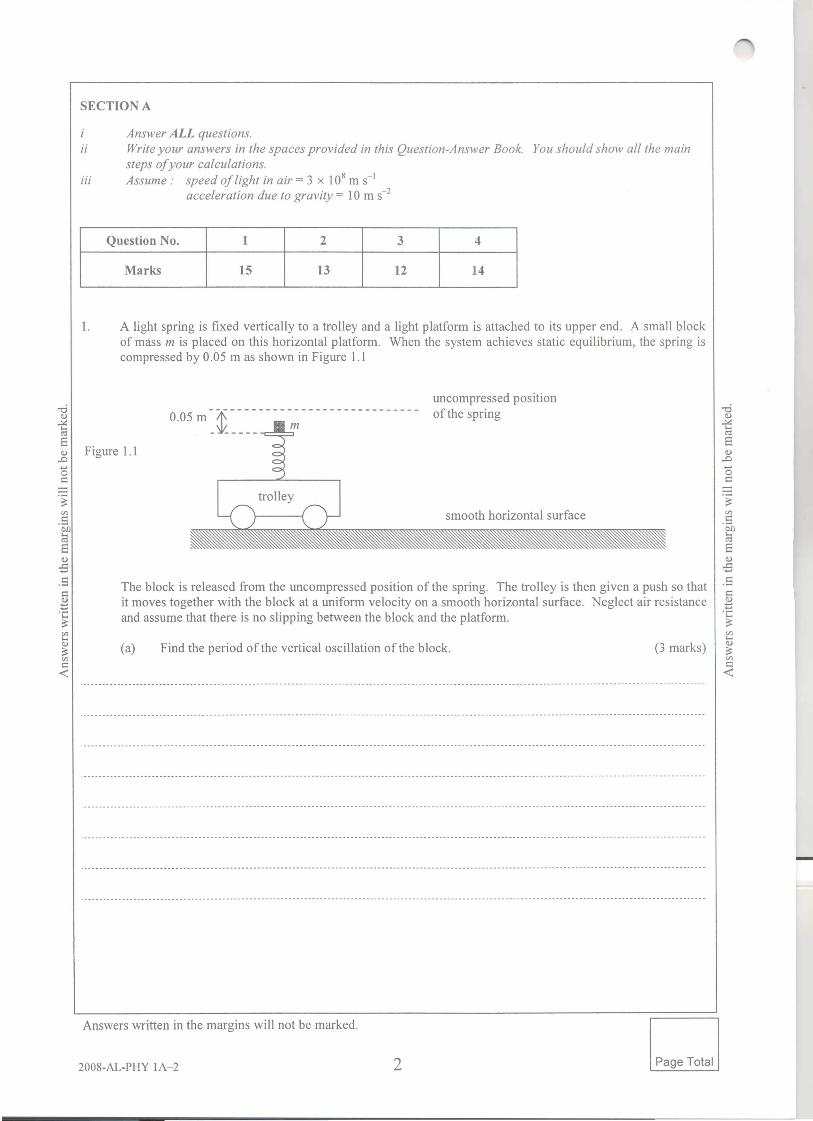
1. A light spring is fixed vertically to a trolley and a light platform is attached to its upper end. A small blockof mass m is placed on this horizontal platform. When the system achieves static equilibrium, the spring iscompressed by 0.05 m as shown in Figure 1.1
uncompressed positionof the spring0.05 m ~~ ~~~~- - - - - - - - - - - - - - - - - - - - - --
The block is released from the uncompressed position of the spring. The trolley is then given a push so thatit moves together with the block at a uniform velocity on a smooth horizontal surface. Neglect air resistanceand assume that there is no slipping between the block and the platform.

I Go on to the next page> Page Total

(iii) Suppose the mass of the block is halved and the force constant of the spring is doubled whileits natural length remains unchanged. If the block is again released from the same positionand the trolley is given the same uniform velocity as before, find the block's period ofoscillation and draw the corresponding stroboscopic photograph in Figure 1.2. Use X toindicate the position of the block. (5 marks)
-dQ)~ ---------------------------------------------.--------------------------------------------------------------------------------------.-----------------------------
SQ) .- - - --- - - - ---- - - - - - ----- - - - - --- - - - - - - - - - - - - - - - - - --- - - - - - - --- - - - - - - - - -- - - - - - - ------ ------ - -- - - - -- - - - - -- -- - - -- - - - -- - - - - - - - - - - - ---- - -- - - - - - - - - - - - - - - - -- -- - ----- - - - ---,D
'0s:: The trolley is stopped suddenly when the block is just at its highest position. The block slips on
the platform and then moves off from it. Describe and explain the subsequent motion of the blockas seen by a stationary observer on the ground. (3 marks)
--.~rn.5~S .---------------------------------------------- ----------.- - -.------------------------------------------.. -.-----------------------------------Q)-B.5s::.~ .. - -- --- ------ - - - - - -- - - - - --- - - - - ---- - -- - -- - - - -- - - -- - - - - - - --- - --------- - - - - - - --- --- ------ - - - - - - --. - - - -- -- - - -- - - - -- - - - - - - - - - - ------ - - - - - - - - - -- - -.- --. -- .•...~~ ----------------------------------------------------------------------------------------------------------------------.----------------_._-------_._--_ .
~rns::
<r::

2. Longitudinal waves can be produced in a metallic slinky spring and the propagation speed of the waves is
. I . b JkL2happroxunate y given y v = -;;; were
k = force constant of the slinky springL = length of the slinky springm = mass of the slinky spring
A student conducts an experiment to verify this relationship. The spring is stretched to a length of2.2 mas-d shown in Figure 2.2. A battery is connected across the spring and two search coils are placed at A and B '"0V v"5 which are at a fixed distance 1.0 m apart. The search coils are connected to the respective Y-inputs of a dual ~,y ti38 trace CRO. E
.~tIl
.5~8.,g Figure 2.2+-"
I...j
~11111111111111111111111111A B
search • 1.0 m •coil D
A sharp push is made at the left end of the slinky spring so that a compression pulse travels along the spring.When the compression pulse passes the search coil at A, the following trace is described on the screen of theCRO.
I Go on to the nextpage> Page Total

(c) The time interval for the pulse to travel from A to B can be found from the corresponding tracesregistered by the search coils. The experiment is repeated with the slinky spring stretched todifferent lengths and the corresponding time intervals found are tabulated below.
Complete the table by choosing a suitable physical quantity and plot a straight line graph to -d(l)
verify the given relationship. (4 marks) ~<I:S
E(l)..0•..os::
Length of the slinky spring, L / m 2.2 2.0 1.8 1.6 1.4
Time interval for the pulse to0.51 0.56 0.62 0.70 0.79travel from A to B, t / s
, .; ;'; + ", i,,:
:·-i··';·_·;'·+-;
,; :
:

Calculate the slope of the graph obtained. Hence, estimate a value for the force constant kwhen the mass of the spring is 0.25 kg. (3 marks)
Another student wants to verify whether the propagation speed of the waves is inverselyproportional to the square root of the spring's mass. He suggests using slinky springs of .£3different masses stretched to the same length to repeat the experiment. Explain whether he .5can verify this relationship by plotting a suitable straight line graph. (2 marks) ~
.~•....$
I Go on to the next page > Page Total

3. A student employs the experimental set-up in Figure 3.1 to study a piece of glass of refractive index 1.5coated with a thin film of refractive index 1.22.
Diagram NOTdrawn to scale
diffractiongrating
thin coating,refractive index 1.22
-dCl)
]EWhite light of continuous spectrum from 400 nm to 700 nm is shone normally onto the coated glass. The Cl)
light reflected by the coated glass is partly reflected by a 45° partially silvered mirror and incident ::onormally on a diffraction grating with 1000 lines per rom. The colour spectra produced are observed on t::
the screen. ~en
What is the highest order of complete colour spectrum produced? Explain briefly with the aid of .~•...calculations. (3 marks) S
.5 .------ --------- -.--------------------.-.-.------.--.----.-----------------------..----.--.-----------------------------------------.--------------------
~.;::~

(b) In the fIrst-order spectrum produced by the diffraction grating, an intensity minimum is observed atan angular position 33°.
(ii) Which interface(s) of the coated glass will generate a TC phase change to the reflectedlight? Explain why there is an intensity minimum in the spectrum. Hence, estimate theminimum possible thickness of the coating on the glass. (5 marks)
.§:en.S ..--.. -------------------------------------.-----------------------------------------------------------------------------------------------.---.------------------
~S
(c) The student suggests that the thickness of the coating could be determined more accurately whenthe white light source is replaced by a monochromatic laser. Comment on the suggestion.(2 marks)
I Go on to the next page> Page Total

4. A certain d.c. motor designed to work from a 12 V supply of negligible internal resistance has an armatureresistance of 0.25 n. When running freely without any mechanical load, the motor draws a current of2.0 A from the supply. The magnetic field provided by two curved pole pieces is always parallel to theplane of the armature coil.
Figure 4.1 shows the side view of the armature coil. At the moment shown, the current is "2into the paper through arm P while it is out of the paper through arm Q. Indicate the ~directions of the magnetic forces acting on the arms P and Q. State the sense of rotation 6of the coil. (2 marks) Q)B' ~~-.~
'".S~ Figure 4.16Q).s.SI:::Q)
.~•...~'"•...Q)
~'"~
'"•...Q)
~'"~
The motor is now connected to a mechanical load, and its running speed becomes 80% of the free <Crunning speed when steady state is reached. Calculate
(i) the corresponding back e.m.f.,(ii) the current drawn from the supply,(iii) the torque on the armature coil if it is a rectangular coil of 50 turns and area
9.0 x 10⁻⁴ m2; and the magnetic field B is 0.1 T.

~ ~v . .. __.__ _ _ _. v
~ ~E _._._ _ __ _.. _ .__.. _._ __.. __ E
(d) With the motor connected to the mechanical load, sketch the time variation of the current drawnfrom the supply when the motor is switched on. Mark the known current values on the verticalaxis. (2 marks)
current
Sources of materials used in this paper will be acknowledged in the Examination Report and Question Paperspublished by the Hong Kong Examinations and Assessment Authority at a later stage.
Answers written in the margins will not be marked.

Answer ALL questions.ii Write your answers in the spaces provided in this Question-Answer Book. You should show all the main
steps of your calculations.iii Assume: speed of light in air = 3 x 10⁸ m S-1
acceleration due to gravity = 10 m S-2
5. In Figure 5.1, a toy is placed on a smooth horizontal surface. It is equipped with a fan powered by a battery.When the fan is switched on, the toy moves to the right and reaches a constant speed eventually.
-d<I.l
]E<I.l.D.•...o . _. _ _s=
With the aid of a speed-time graph, explain the motion of the toy after the fan is switched on.(4 marks)
--.~ ._---------------------------------_ ..__ _.------._ _---_ ..__ _ .._-_._-----'".S~E<I.l-B -- - -------.-----.------- -------.- --------------------.Ss=Q) ._----------------------------_ .••••••• _------.-------------------------------.-- .. _._----------_ ..
'E;::'"•...<I.l;::Cf) . • • -----------------------------------. ••
s=-<r.: The toy of total mass m is now attached to a fixed point on the ceiling by a light inextensible stringof length L. It is set into a uniform horizontal circular motion as shown in Figure 5.2. The stringmakes an angle e to the vertical when the speed of the toy is v.
. ..........
.............

••-d0..><:ae0.0•....0s::-.~'".50/}ae0..s::•.....5s::0
.1E•....~'"•....0~'"s::«
Write down TWO equations of motion of the toy. Hence, show that the angle e satisfies theequation 2 cos2e + cos e - 2 = 0 if m = 0.1 kg, L = 0.8 m and v = 2 m S-l and calculate thevalues of e and T. (5 marks)
(iii) If the output voltage of the battery inside the toy drops slightly, describe and explain itssubsequent motion in terms of v, e and T. (3 marks)
I Go on to the next page> Page Total

6. The set-up shown in Figure 6.1 is used to study photoelectric effect. Light of a certain frequency isdirected towards the photo-sensitive electrode B of a photocell. The potential difference across theelectrodes A and B can be varied by adjusting the variable supply.Given Planck constant h = 6.63 X 10⁻³⁴ J s
Charge of electron e = 1.60 X 10⁻¹⁹ C
--1 electrometer Ilight
~ photocell
AI ~IBI I
variablesupply
(a) When the voltage VB of the electrode B is zero, the electrometer still detects a current. Explain thisphenomenon and state the direction of the current in the photocell. (2 marks)
-cieu~ -- - -
aeu.D .........................•............•••.••. --- .........••.••.... ---- - -.. -................•.... -- .•..••••••••.................•.....•...ot=- ._--------------------------------------------.------------------------------------------------.---------------.--------------------------------------------------
.~'".5~a
The work function of electrode B IS 2.3 eV. The graph in Figure 6.2 shows the variation of thecurrent f with the voltage VB when the variable supply is adjusted.
fila-loA
""

What is the maximum kinetic energy, in eV, of the photoelectrons produced? Hence, findthe wavelength of the light waves used and name this kind oflight waves. (4 marks)
.-~_ ..- _. - - - - - - - - - - - - - - - - - - - - - - - - - - - - - - - - - - - - - - - - - - - - - - - - - - - - - - - - - - - - - - - - - - - - - - - - - - - - - - - - - - - - - - - - - - - - - - - - - - - - - - - - - - - - - - - - - - - - - - - - - - - - - - - - - - - - - - - - - - - - - - - - - - - - - - - --~ ~~ ~~ _---- -- _ _ .._- _-_ __ --- -_._ _ _--- - _ __ ..- ..-._._. ~8 8
--.~ .------.-------------------------------------------------------.--------------------------------------------------------------------------------------------------
.5~8
.5 _.__.._. ._ _ _._.._.__ _._ _ _ .._._ _ .
.~•....~
In Figure 6.2, sketch the current-voltage variation when the experiment is repeated with thelight intensity doubled. (2 marks)
Referring to the graphs in Figure 6.2, elaborate one observation of the photoelectric effect thatcannot be explained by the wave theory. (2 marks)
I Go on to the next page> Page Total

Figure 7.1 shows an LRC circuit connected to an a.c. source of variable frequency and negligibleimpedance. The r.m.s. voltage Vs of the source IS 10 V. The resistance of the resistor R is 40 nand L is apure inductor.
r.m.s. voltage acrossthe resistor VRI V
//
/
~ R/11
/
V/
0.2 0.4 0.6 0.8 1.0 1.2 1.4 1.6 1.8 2.0 2.2 2.4 2.6 28frequency f/ kHz
With the switch S open and the variable capacitor C set at 1 JlF, the frequency f of the source isvaried and the corresponding variation of the r.m.s. voltage VR across the resistor is shown in theabove graph.
(i) Determine the resonant frequency fa and the maximum value of the r.m.s. current.(3 marks)
.~en.s .----------------------------------------------------------------------------------------------------------- . aa
~aII).p.5s::
.~....~~II) .•••_••-_••_••••.- - -- - - - - - -. - ••- -_. - - - - - - _••_._••••••••- _••--. - -- _. - - -- -- - - - - - - - - - - -- _. - -- ••••••-_._•••••-_•••_•••.. - - - - - - - - -- _. - - -- ••••- -- -- -- - -- -- -- - -- - _•••••••
~ens::<
(ii) At resonance, the r.m.s. voltage VL across the inductor is 25 V, which is greater than ther.m.s. voltage of the source. Explain why this is so and find the inductance L. (3 marks)

(b) With the switch S still open and the frequency of the source fixed at a certain value ii, thecapacitance of the capacitor C is varied so as to study the average power P dissipated in the circuit.
"0 .............•••••..•••.•••.••.•••... - ...••.•••••••... - .. -.- .••••.•.................... - ..•........................................ - --.- .. - .II)
]SII)
.D
os::Calculate the maximum value of P and state the condition for attaining this value.
(3 marks).~tn .. _---- .. ------------------------------------------------------------------.--------------------------------------------------------------------------------------.S~S
.5 .-.------------.--._--_... -------.------..-..... ------__..... e ••• .------------------.------------------------------.----
s::.~ _. __ ._-_ .
~rnl-l .-----------------------------------.----.----------.--.--.----------------------- •••-- ••••••••••••• --------------- ••••••••• ------------.-.--.---------.- •••••••••II)
~~
(c) With the switch S closed and the capacitance fixed, sketch the variation of the Lm.S. voltageacross the resistor with the frequency of the source. (2 marks)
r.m.s. voltage acrossthe resistor VR
I Goon to the next page> Page Total
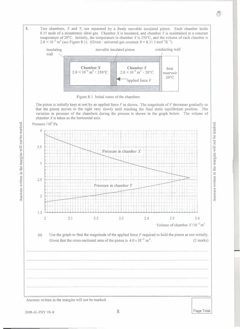
8. Two chambers, X and Y, are separated by a freely movable insulated piston. Each chamber holds0.15 mole of a monatomic ideal gas. Chamber X is insulated, and chamber Y is maintained at a constanttemperature of 20°C. Initially, the temperature in chamber X is 350°C, and the volume of each chamber is2.0 x 10-3 m3 (see Figure 8.1). (Given: universal gas constant R = 8.31 J mor1K-1)
insulatingwall / I
"'- /I
Chamber X Chamber Y heat2.0 x 10-3 m3 , 350°C 2.0 X 10⁻³ m3 ,20°C reservoir
....• 20DC....• applied force F
Figure 8.1 Initial states of the chambers
The piston is initially kept at rest by an applied force F as shown. The magnitude of F decreases gradually sothat the piston moves to the right very slowly until reaching the final static equilibrium position. Thevariation in pressure of the chambers during the process is shown in the graph below. The volume ofchamber X is taken as the horizontal axis.
Pressure II 05 Pa
(a) Use the graph to find the magnitude of the applied force F required to hold the piston at rest initially.Given that the cross-sectional area of the piston is 4.0 x 10⁻³ m 2. (2 marks)

-ci .-------------------------------------------------------------------------------- - - .. -------- -- ---------- --.-------------------------------v
~SV.D.•...o .---------------------------------------------------------------------------------.------------------.- ------- ---------.-------------------I::
.~ ._--------------------------------------------------------------------------------------------------------------.-------------------------------------------------
.5~sv .------------------------------------------------------------------------------------------------------------------------------------------------------------------B.5c:: .-----------------------------------------------------------------------------------------------------------------------------------------------------------------vtl'C~
I Go on to the next page > Page Total

(iii) the work done on the gas in chamber Y, given that the gas in chamber X does a work of 58 Jagainst the applied force F, (2 marks)
-dQ)~ .--------------------------------- ------ ..-- ---------- ..- ---------------------------------------.---- --.--.-----------------.-----
EQ) ._--------------------------------------------_ ••••••••• -------_._._---_._._------------------------------------- -----------_ •• _----_ •••• -.--------------- --------.0~os::-.~.S .------------------------------------------- ------------- -------------------------------------------------.------------------------.-------~E
.5 -----.---------.--.----------------------------------- -----------------------------------------------------------------..-------.-- -----------------s::.~•...~~ . - --- - - - -- --- - -_ .....--.- - - - - - - - - - --- ---- - -- - -- - - ---- - -- - -- - - - ---- - - -_ .... - - - --~~~.~---.--- - - ---- - - - -- -- - - -- --. -~- - ---.- - - - - -- - - - - - -- -- - - -- - ---- - - - - - - - - - - _. _ ..-_.~~ (iv) the heat absorbed or liberated by the gas in chamber Y. (2 marks)
Sources of materials used in this paper will be acknowledged in the Examination Report and Question Paperspublished by the Hong Kong Examinations and Assessment Authority at a later stage.

u22a=-=OJ r
r
F= Gmtm2r2
U=_GMmr
r 3 / T2 = constant
u=~
d=ADa
1210 loglO(-)II
1 1 1-+-=-U v f
E= Q41r&or2
V=_Q-41r&or
E=Vd
C=Q=&oAV d
Q = Qo(l-e-tIRC)
E = ~CV22
1 =nAuQ
R= piA
F = BQusinB
V= BIC12.nQt
velocity of transverse wave motion in astretched string
velocity oflongitudinal wave motion ina solid
electric field strength due to a pointcharge
electric field between parallel plates(numerically)
decay of charge with time when acapacitor discharges
rise of charge with time when charginga capacitor
force on a moving charge in a magneticfield
force on a current-carrying conductor ina magnetic field
fLo 1B=-
2wfLoN1B=--I
F = fLOII/22w
f. = -L dIdt
E =~LI22
1XC=-we
1 """2pV=-Nmc
3
E = 3RT =~kTk 2N 2A
E=:/~1
E=-Fx2
F=- dUdr
1P+_pu2 +pgh
2
!-'U=Q+W
E = _13.6 eVn n2
In2t I
"2 k
~mu2 = hv-if>2 m
E = mc2
force per unit length between long parallelstraight current-carrying conductors
torque on a rectangular current-carryingcoil in a uniform magnetic field
ratio of secondary voltage to primaryvoltage in a transformer
macroscopic definition of Youngmodulus
relationship between force and potentialenergy