ansys 14.0 fluid dynamics update - dipankar choudhury
DESCRIPTION
Update include rapid and robust meshing, workflow and usability, HPC and solver speed, rotating machinery, automotive and multiphase applications as well as overall to providecomprehensive CFDTRANSCRIPT

© 2011 ANSYS, Inc. October 24, 20111
ANSYS Fluid Dynamics Update
Dipankar ChoudhuryVP, Research

© 2011 ANSYS, Inc. October 24, 20112
ANSYS Fluid Dynamics
ANSYS Fluid Dynamics Products• ANSYS FLUENT• ANSYS CFX• ANSYS CFD‐Post• ANSYS TurboGrid• ANSYS Polyflow
ANSYS Fluids Dynamics at 14.0• Significant benefits for users
• Including geometry and meshing• Look for detailed materials at release time
© 2011 ANSYS, Inc. October 24, 20113
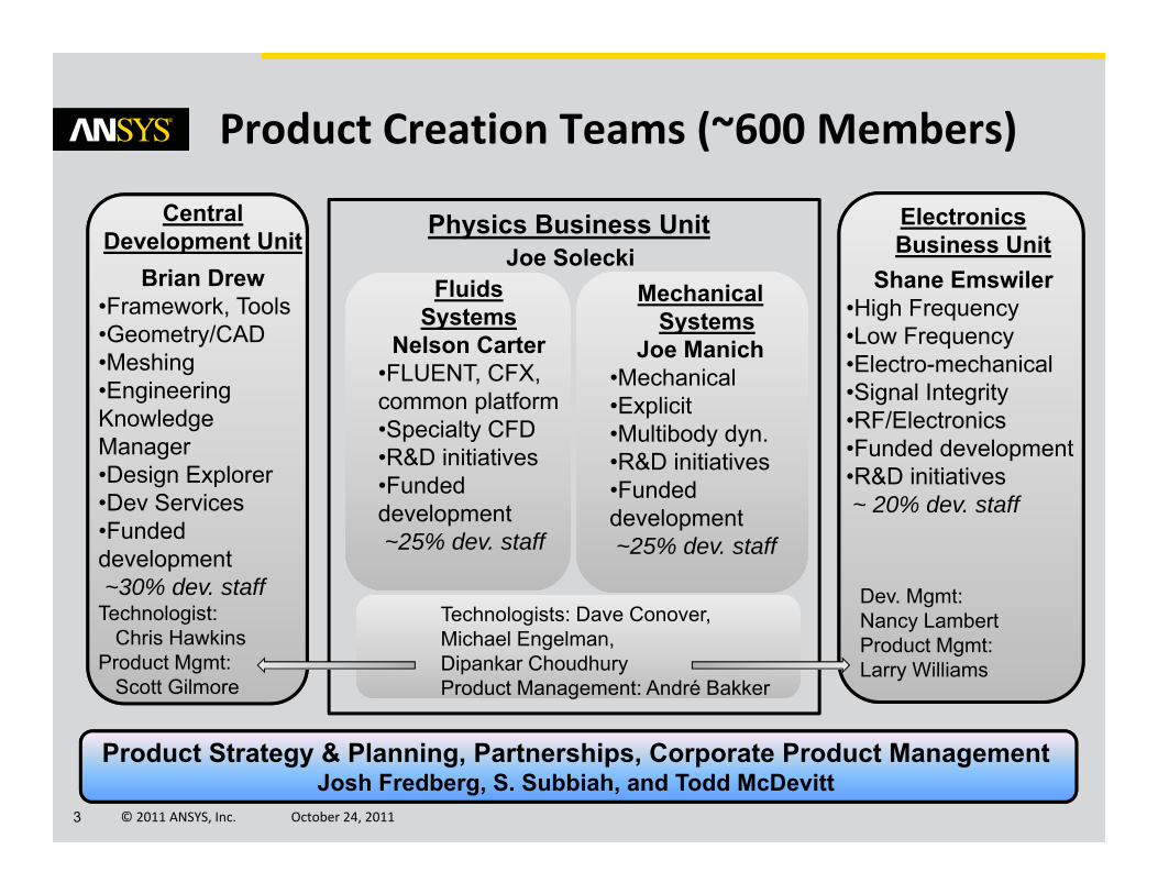
Product Creation Teams (~600 Members)
CentralDevelopment Unit
Brian Drew•Framework, Tools•Geometry/CAD•Meshing•Engineering KnowledgeManager•Design Explorer•Dev Services•Funded development~30% dev. staff
Technologist:Chris Hawkins
Product Mgmt: Scott Gilmore
FluidsSystems
Nelson Carter•FLUENT, CFX, common platform•Specialty CFD•R&D initiatives•Funded development~25% dev. staff
MechanicalSystems
Joe Manich•Mechanical•Explicit•Multibody dyn.•R&D initiatives•Funded development~25% dev. staff
Physics Business UnitJoe Solecki
Technologists: Dave Conover, Michael Engelman, Dipankar ChoudhuryProduct Management: André Bakker
Electronics Business Unit
Shane Emswiler•High Frequency•Low Frequency•Electro-mechanical•Signal Integrity•RF/Electronics•Funded development•R&D initiatives~ 20% dev. staff
Dev. Mgmt:Nancy LambertProduct Mgmt: Larry Williams
Product Strategy & Planning, Partnerships, Corporate Product ManagementJosh Fredberg, S. Subbiah, and Todd McDevitt

© 2011 ANSYS, Inc. October 24, 20114
We remain committed to developing and releasing an integrated, unified fluids product• That will draw upon the best of both FLUENT and CFX, as well as add new functionality
• That will minimize migration hurdles for our fluids customers
The first release of this product is targeted for ANSYS R15.0
FLUENT and CFX will continue to be developed in the meantime (and actively maintained for a few releases beyond R15.0)• To ensure smooth migration for our fluids customers
Our Fluids Strategy
© 2011 ANSYS, Inc. October 24, 20115
• Rapid & Robust Meshing
• Workflow & Usability
• Multiphysics and Systems Coupling
• Solver and HPC Performance
• Rotating Machinery
• Automotive Power Train Modeling
• Multiphase Flow Modeling
• Comprehensive CFD Capabilities
• Special Material Processing
• Summary
Fluid Dynamics Themes
© 2011 ANSYS, Inc. October 24, 20116
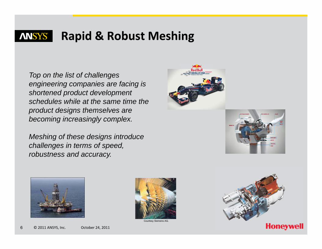
Rapid & Robust Meshing
Top on the list of challenges engineering companies are facing is shortened product development schedules while at the same time the product designs themselves are becoming increasingly complex.
Meshing of these designs introduce challenges in terms of speed, robustness and accuracy.
Courtesy Siemens AG.

© 2011 ANSYS, Inc. October 24, 20117
Rapid & Robust Meshing
Enhanced productivity through increased automation, flexibility, efficiency and robustness
• Assembly Meshing (Tet and CutCell)• Performance (Speed, Robustness)• Selective Meshing• Virtual Topologies• Hex Meshing• ICEM CFD/TGrid

© 2011 ANSYS, Inc. October 24, 20118
Workflow & Usability
Simulation departments are looking for improved usability and the ability to glean more information from fluid dynamics simulations for all users –from occasional designers to experienced analysts – from geometry creation through post-processing.

© 2011 ANSYS, Inc. October 24, 20119
Workflow & Usability – Geometry Advances
Focus on enhancing your productivity through new features, increased flexibility, efficiency and usability• ANSYS DesignModeler– Core modeling improvements– Application‐specific modeling
• ANSYS SpaceClaim Direct Modeler– Improved Workbench integration– Enhanced Model Preparation
• Interoperability– Support for new CAD releases – New CAD file readers

© 2011 ANSYS, Inc. October 24, 201110
• Workbench Design Exploration and Optimization for increased understanding, innovation & simulation ROI
• New at 14.0• Reduced time required
• 2 new adaptive DOEs • Distributed solve• Design point sorting
• Increased Robustness• Reserved licensing
• Support for partial DOE’s
• Increased understanding• New charts• Improved GOF• Project report
Workflow & Usability – ANSYS DX
Single Physics
Multiphysics
“What if” Study
Design Exploration
Optimization
Robust Design
R14

© 2011 ANSYS, Inc. October 24, 201111
ANSYS Remote Solver Manager at R14 (FL and CFX)
• Major improvements for fluids as well as general usability and robustness improvements to RSM
• Queue multiple jobs on a local machine– Overnight or other low‐usage times
• Submit jobs to remote machines– Distributed clusters– Management of files, including UDFs
• Update design points in parallel via RSM
Workflow & Usability – ANSYS RSM

© 2011 ANSYS, Inc. October 24, 201112
Workflow & Usability – ANSYS CFD
Improved workflow and usabilityin ANSYS Workbench • Extended User Preferences (FL)– General options– Launcher options
• Extended parameters for FLUENT– Real and profiles variables in zone and domain settings
– Examples:• Phases: Nucleation Rate, Coalescence and Breakage Kernels• Phase Interaction: Surface Tension Coefficients, Lift Coefficient, Restitution Coefficient
• Contact Angles (on wall BC)
© 2011 ANSYS, Inc. October 24, 201113
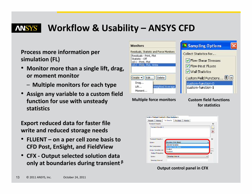
Workflow & Usability – ANSYS CFD
Process more information per simulation (FL)• Monitor more than a single lift, drag, or moment monitor– Multiple monitors for each type
• Assign any variable to a custom field function for use with unsteady statistics
Export reduced data for faster file write and reduced storage needs• FLUENT – on a per cell zone basis to CFD Post, EnSight, and FieldView
• CFX ‐ Output selected solution data only at boundaries during transient β
Multiple force monitors Custom field functions for statistics
Output control panel in CFX
© 2011 ANSYS, Inc. October 24, 201114
Workflow & Usability – ANSYS CFD
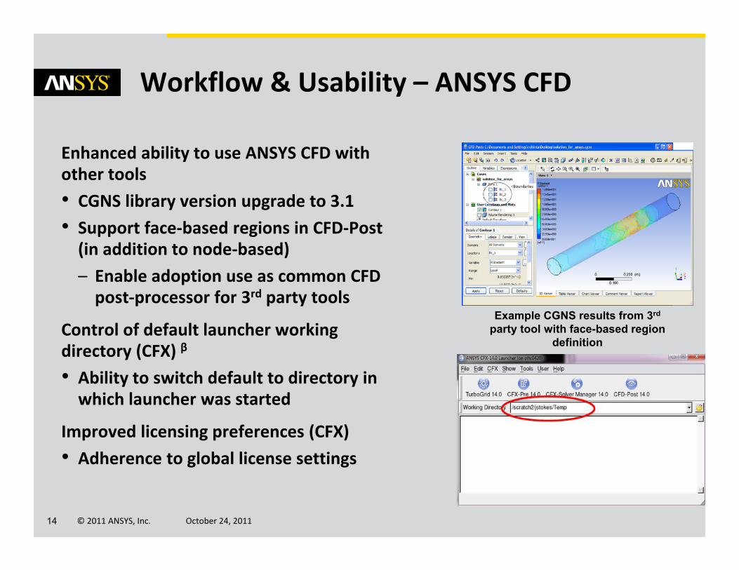
Enhanced ability to use ANSYS CFD with other tools• CGNS library version upgrade to 3.1• Support face‐based regions in CFD‐Post (in addition to node‐based)– Enable adoption use as common CFD post‐processor for 3rd party tools
Control of default launcher working directory (CFX) β
• Ability to switch default to directory in which launcher was started
Improved licensing preferences (CFX)• Adherence to global license settings
Example CGNS results from 3rd
party tool with face-based region definition
© 2011 ANSYS, Inc. October 24, 201115
Workflow & Usability – ANSYS CFD
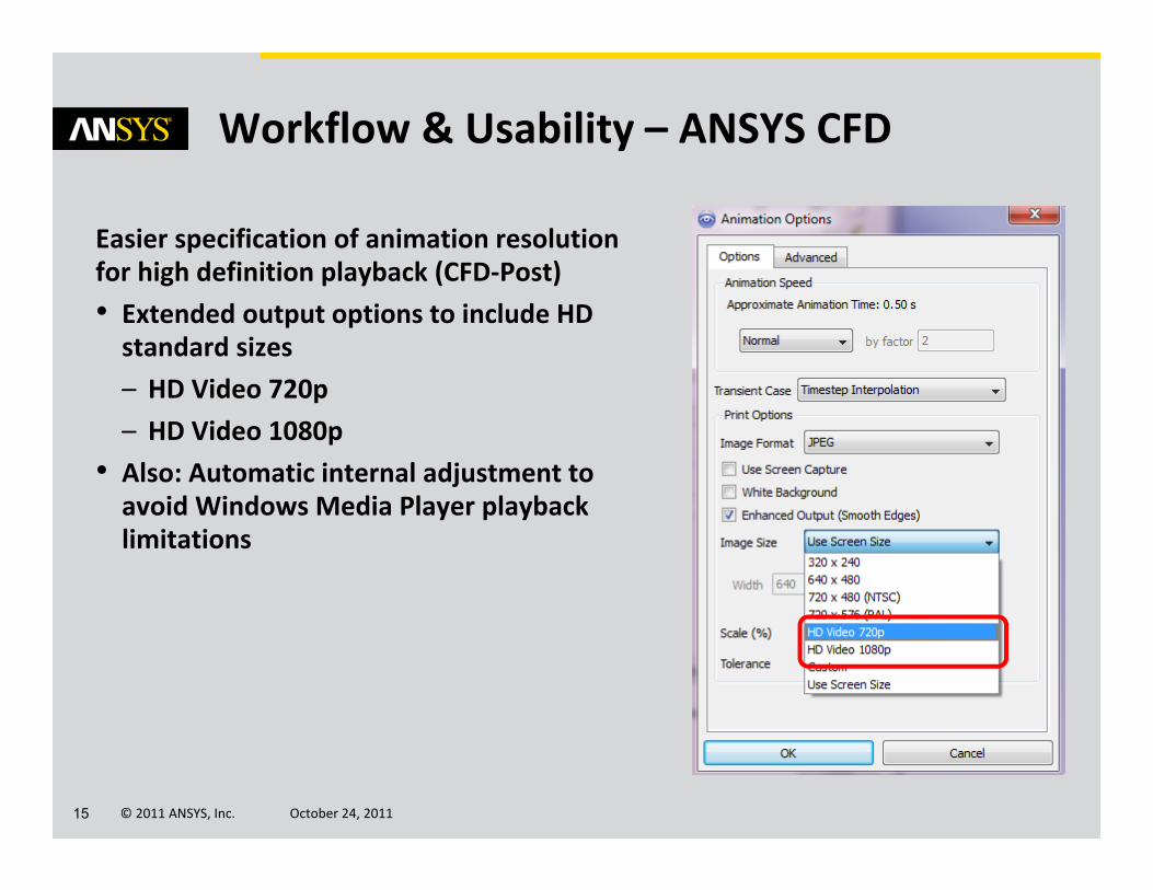
Easier specification of animation resolution for high definition playback (CFD‐Post)• Extended output options to include HD standard sizes– HD Video 720p– HD Video 1080p
• Also: Automatic internal adjustment to avoid Windows Media Player playback limitations

© 2011 ANSYS, Inc. October 24, 201116
Multiphysics and Systems Coupling
Engineers need to accurately predict how complex products behave in real-world environments with real world physics.
ANSYS is continuously improving the ease of use and efficiency of simulating real world interactions between fluid dynamics, structural mechanics, heat transfer, and electromagnetics within a single, unified engineering simulation environment using systems coupling.
© 2011 ANSYS, Inc. October 24, 201117
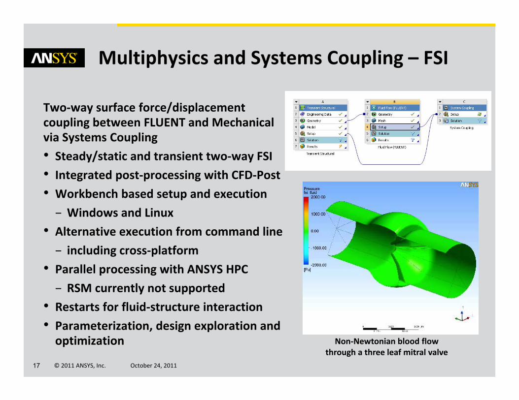
Two‐way surface force/displacement coupling between FLUENT and Mechanical via Systems Coupling• Steady/static and transient two‐way FSI• Integrated post‐processing with CFD‐Post• Workbench based setup and execution
– Windows and Linux• Alternative execution from command line
– including cross‐platform• Parallel processing with ANSYS HPC
– RSM currently not supported• Restarts for fluid‐structure interaction• Parameterization, design exploration and optimization
Multiphysics and Systems Coupling – FSI
Non‐Newtonian blood flow through a three leaf mitral valve
© 2011 ANSYS, Inc. October 24, 201118
Multiphysics – 1‐way FSI
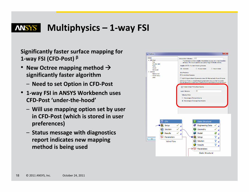
Significantly faster surface mapping for 1‐way FSI (CFD‐Post) β
• New Octree mapping method significantly faster algorithm – Need to set Option in CFD‐Post
• 1‐way FSI in ANSYS Workbench uses CFD‐Post ‘under‐the‐hood’– Will use mapping option set by user in CFD‐Post (which is stored in user preferences)
– Status message with diagnostics report indicates new mapping method is being used

© 2011 ANSYS, Inc. October 24, 201119
Multiphysics – FLUENT‐Maxwell‐Mechanical
Complex multiphysics modeling• New: Electromagentic‐thermal interactions inside Workbench using FLUENT with Maxwell– One‐way and two‐way β coupling
• Combine with 1‐way FSI
β

© 2011 ANSYS, Inc. October 24, 201120
Solver and HPC Performance
Companies need to make informed development decisions about their increasingly complex products in increasingly shorter time frames.
Cou
rtesy
Sie
men
s

© 2011 ANSYS, Inc. October 24, 201121
Solver and HPC Performance – Adjoint Solver
Adjoint Solver for FLUENT fully tested, documented, and supported at R14.0
• Provides information about a fluid system that is very difficult and expensive to gather otherwise
• Computes the derivative of an engineering quantity with respect to inputs for the system
• Engineering quantities available– Down‐force, Drag, Pressure drop
• Robust for large meshes– Tested up to ~15M cell
Shape sensitivity to down‐force on a F1 car
Shape sensitivity to lift on NACA 0012
Lift Force (N)Geometry Predicted ResultOriginal ‐‐‐ 555.26Mod. 1 577.7 578.3Mod. 2 600.7 599.7Mod. 3 622 621.8

© 2011 ANSYS, Inc. October 24, 201122
Solver and HPC PerformanceMesh Morpher and Optimizer
FLUENT Mesh Morpher and Optimizer• Create your own optimization functions using parameters
• Faster mesh deformation• Constrain some boundaries and allow others to deform
• More easily assess the effectiveness of the optimization routine– Save and plot the value of the objective function as a function of design iteration number
• Execute TUI commands before and after the optimization loop
Objective function definition panel
Example data showing faster mesh deformation
Objective function as a function of design stage

© 2011 ANSYS, Inc. October 24, 201123
Solver and HPC Performance
Focus on robustness, accuracy, and efficiency
• Improved performance (FL)– Out of the box performance
• New defaults– 2nd order for some equations– hybrid initialization
• Solver optimizations– Higher order term relaxation (HOTR)
• More aggressive initial settings• Improved convergence
– Migration manual
• Beta: NRBCs with PBNS (FL)– Compatible with combustion models
RAE‐2822 AirfoilM=0.73AOA=2.8 deg
Standard @ CFL=200
HOTR @ CFL=200
Standard @ CFL=100
HOTR @ CFL=100
Normalized scales residuals comparing HOTR to standard relaxation at different CFL settings
Diverges

© 2011 ANSYS, Inc. October 24, 201124
Solver and HPC Performance
Faster convergence on stretched meshes
• Convergence Acceleration for Stretched Meshes (CASM) with the density‐based implicit solver
• Recommended for:– Steady‐state simulations– Anisotropic meshes with high stretching in the local flow direction
– Stretched meshes with Y+ near 1
CdStandardCASM
Convergence acceleration for stretched meshes requires nearly 10x fewer iterations in this case
(300 vs. 3000 iterations)
RAE-Wing-body 5M=0.8AOA=2.0 deg

© 2011 ANSYS, Inc. October 24, 201125
Solver and HPC Performance
Improved scalability (FL)• Scalability to higher core counts• Simulations with monitors including plotting and printing
• Cluster‐to‐cluster view factor file writing optimization
Hex‐core mesh, F1 car, 130 million cellsmonitor‐enabled
0
5
10
15
20
25
30
35
0 200 400 600 800 1000
Example data for scaling with R14 monitors
3072 cores
Sample cluster‐to‐cluster view factor data writing using 32‐way parallel and Infiniband.
0.4 million surface clusters
1.1 million surface clusters
R13R14

© 2011 ANSYS, Inc. October 24, 201126
Solver and HPC Performance
Faster auto‐partitioning (FL)• Optimized for multi‐core clusters • All simulations benefit • New default• More constant time required with fixed overhead
Improved usability (FL)• Better error tracking• Latest Platform and Intel MPI versions on all platforms
Work in Progress: GPU investigation• R14.0: Viewfactor and ray tracing calculations on GPUs (FL)
Example viewfactor calculation times for different combinations of GPUs and CPUs

© 2011 ANSYS, Inc. October 24, 201127
Solver and HPC Performance
Optimize parallel partitioning in multi‐core clusters (CFX)β
• Partitioner determines number of connections between partitions and optimizes part.‐host assignments
Re‐use previous results to initialize calculations on large problem (CFX) β
• Large case interpolation for cases with >~100M nodes
Clean up of coupled partitioning option for multi‐domain cases (CFX)• Eliminates ‘isolated’ partition spots
Compute Node 1 Compute Node 2
P1
P5
P3
P6
P2 P7
P4 P8
P1P5
P3
P6P2
P7
P4
P8
Partitioning step finds adjacency amongst partitions; partitions with max adjacency are grouped on same compute nodes
© 2011 ANSYS, Inc. October 24, 201128
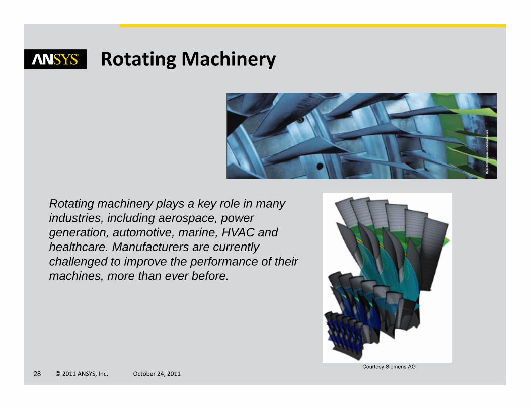
Rotating Machinery
Rotating machinery plays a key role in many industries, including aerospace, power generation, automotive, marine, HVAC and healthcare. Manufacturers are currently challenged to improve the performance of their machines, more than ever before.
Courtesy Siemens AG

© 2011 ANSYS, Inc. October 24, 201129
Rotating Machinery
Highly efficient time accurate simulations with Transient Blade Row capability (CFX)• Several models available– Time Transformation (TT)
• Inlet Disturbance • Single Stage TRS
– Fourier Transformation (FT)• Inlet Disturbance • Single Stage TRS β
• Blade Flutter β
Surface pressure distribution (top) and monitor point pressure (left) from an axial fan stage:
Equivalent solution with Time Transformation at fraction of computational effort
Reference solution without a TBR method, requiring 180 deg model
Time Transformation solution, requiring only
3 stator and 2 fan blades

© 2011 ANSYS, Inc. October 24, 201130
Rotating Machinery
Workflow extensions for Transient Blade Row (CFX)• Incorporation of TBR methods in Turbo setup mode– Switch to general mode for case‐specific details
• Profile replication and clocking for inlet disturbances– Automatically ensure complete circumferential overlap of profile with mesh
– Select profile and specify rotation rate

© 2011 ANSYS, Inc. October 24, 201131
Rotating Machinery
Integrated Transient Blade Row analysis (CFD‐Post)• Full integration of single passage TBR analysis– Each plots can be at selected time or phase position in period being modeled
– Expansion of results (to show multiple passage simultaneously) possible with macro provided with installation β

© 2011 ANSYS, Inc. October 24, 201132
Rotating Machinery
Additional integrated turbo analysis capabilities (CFD‐Post)• Reduce need to export data and manipulate externally
• Directly assess stream‐wise changes in span‐wise distributions of circumferential averages– Look at differences or ratios of existing variables, e.g. pressure ratio
• Further derived data possible with ability to define separate lines
Easier set‐up of monitor points for rotating machinery (CFX) β
• Specification in cylindrical coordinates
© 2011 ANSYS, Inc. October 24, 201133
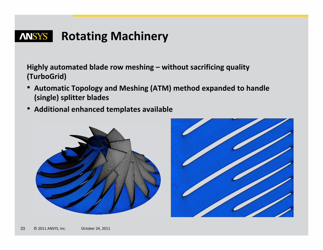
Rotating Machinery
Highly automated blade row meshing – without sacrificing quality (TurboGrid)• Automatic Topology and Meshing (ATM) method expanded to handle (single) splitter blades
• Additional enhanced templates available
© 2011 ANSYS, Inc. October 24, 201134
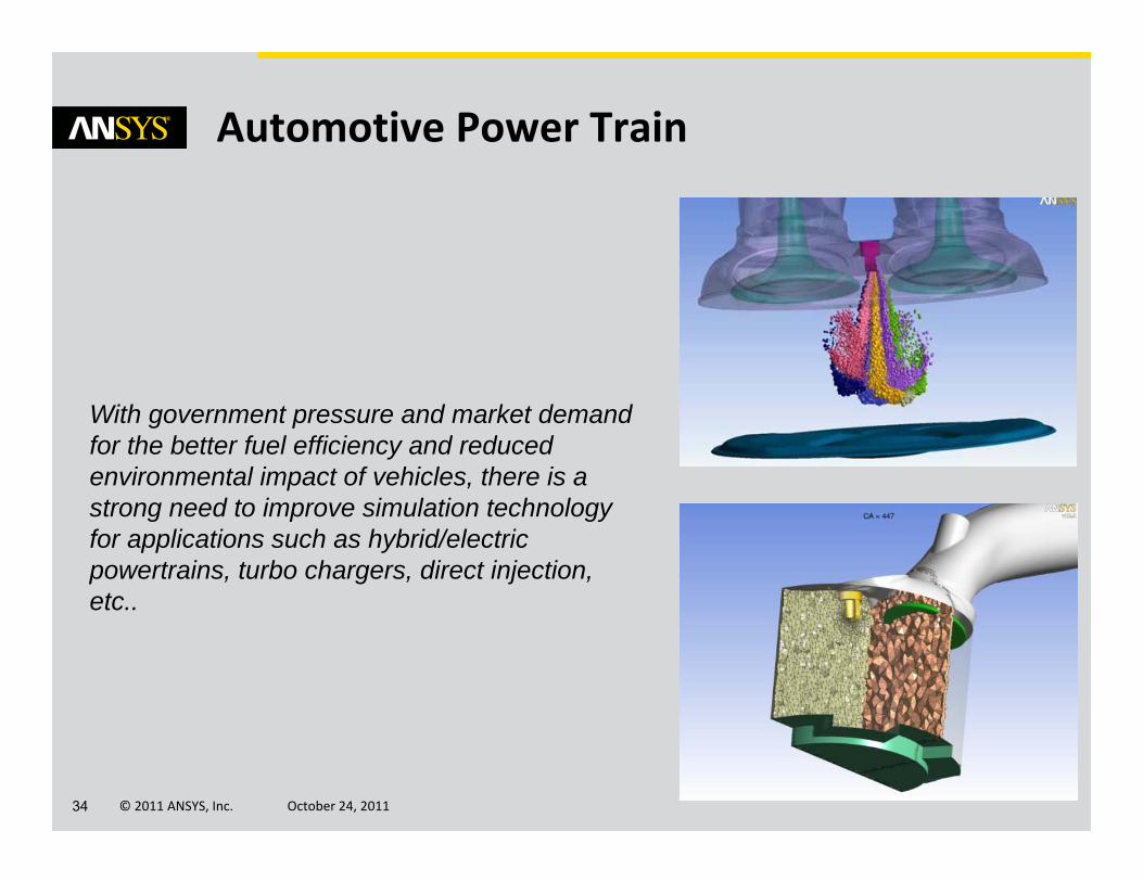
Automotive Power Train
With government pressure and market demand for the better fuel efficiency and reduced environmental impact of vehicles, there is a strong need to improve simulation technology for applications such as hybrid/electric powertrains, turbo chargers, direct injection, etc..

© 2011 ANSYS, Inc. October 24, 201135
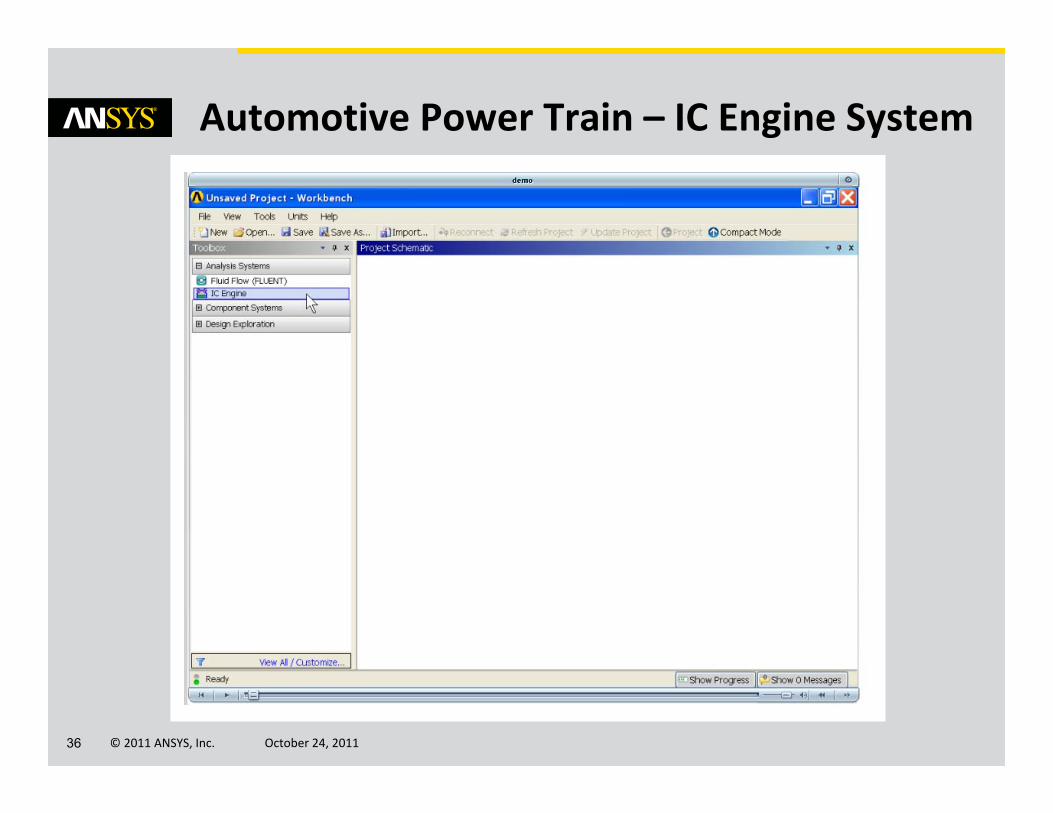
Automotive Power Train – IC Engine System
New for R14: IC Engine Analysis System provides unified and simplified set‐up for internal combustion engines• Controls simulations based on user inputs– Geometry decomposition– Meshing– Dynamic mesh set‐up– Reporting
• Parametric updates• Pervasive use of crank angle• Option to include journal files– Automate combustion and spray set‐up
© 2011 ANSYS, Inc. October 24, 201136
Automotive Power Train – IC Engine System
© 2011 ANSYS, Inc. October 24, 201137
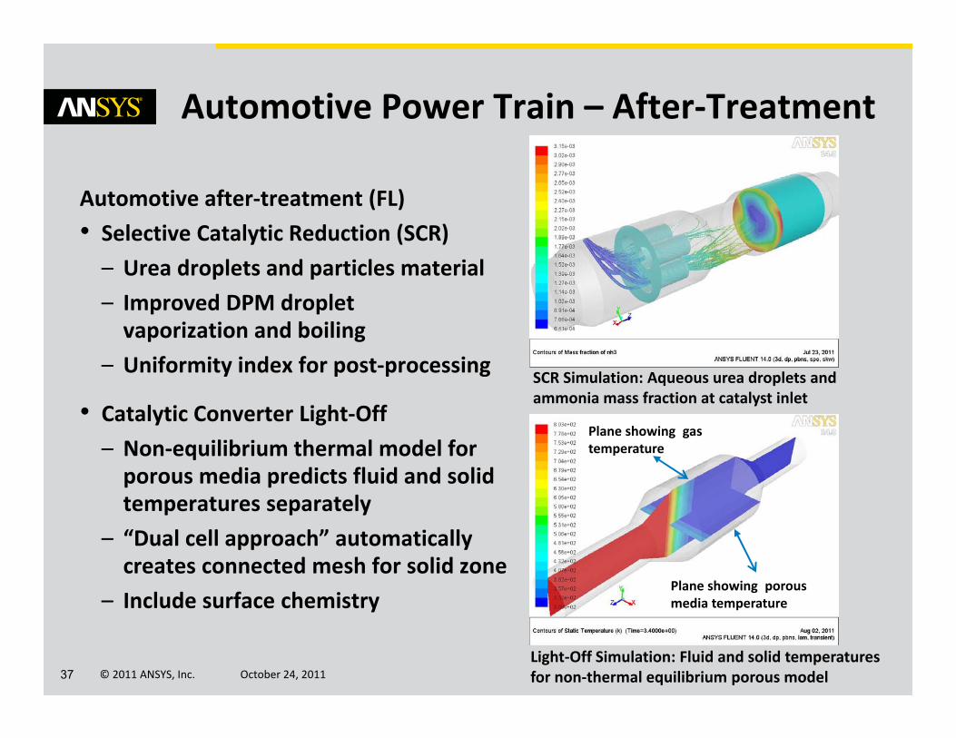
Automotive Power Train – After‐Treatment
Automotive after‐treatment (FL)• Selective Catalytic Reduction (SCR)– Urea droplets and particles material– Improved DPM droplet vaporization and boiling
– Uniformity index for post‐processing
• Catalytic Converter Light‐Off– Non‐equilibrium thermal model for porous media predicts fluid and solid temperatures separately
– “Dual cell approach” automatically creates connected mesh for solid zone
– Include surface chemistry
SCR Simulation: Aqueous urea droplets and ammonia mass fraction at catalyst inlet
Plane showing gas temperature
Plane showing porous media temperature
Light‐Off Simulation: Fluid and solid temperatures for non‐thermal equilibrium porous model

© 2011 ANSYS, Inc. October 24, 201138
Automotive Power Train – Solver meshing
FLUENT MDM improvements driven by internal combustion engine needs • Retain and remesh boundary layers during tetrahedral remeshing (FL)– Boundary layer settings from original mesh
– Example applications: internal combustion engines and FSI
• Improved robustness and usability for dynamic mesh (FL) – Mesh smoothing– Cut cell remeshing– Parallel
T=0 T=25 T=50
Tetrahedral mesh with boundary layers after remeshing
Remeshing a tetrahedral mesh with boundary layers during a simulation

© 2011 ANSYS, Inc. October 24, 201139
Automotive Power Train – Battery Model
FLUENT Battery Model: a pragmatic approach to full‐scale battery computations• Temperature effect on battery dynamics
• Appropriate for various types of batteries
• Robust numerical algorithm for fast convergence
• User‐customizable properties and correlations
Discharge curves for a prismatic Li‐ion cell
Temperature Current DensityContours on a prismatic Li‐ion cell

© 2011 ANSYS, Inc. October 24, 201140
Multiphase Flow Modeling
Many industrial processes involve the simultaneous flow of multiple phases.
Most of these processes are impossible to observe directly. Therefore, engineers rely on models and experiments to gain insight into improving the efficiency, throughput, safety and reliability of their processes.
Courtesy of Petrobras
© 2011 ANSYS, Inc. October 24, 201141
0.00E+00
5.00E‐04
1.00E‐03
1.50E‐03
2.00E‐03
2.50E‐03
0 1 2 3 4 5
Dp (m
)
time (s)
Diffusion‐controlledConvection Diffusion‐controlledExperimental Data – symbols
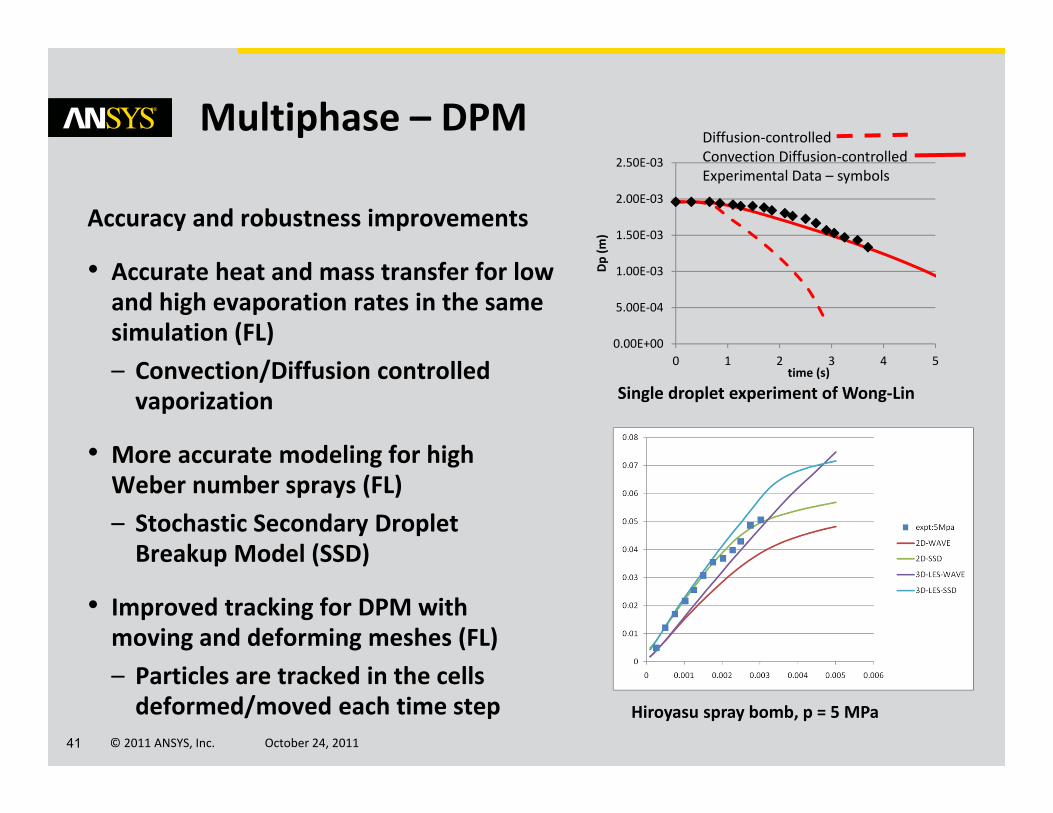
Multiphase – DPM
Accuracy and robustness improvements
• Accurate heat and mass transfer for low and high evaporation rates in the same simulation (FL)– Convection/Diffusion controlled vaporization
• More accurate modeling for high Weber number sprays (FL)– Stochastic Secondary Droplet Breakup Model (SSD)
• Improved tracking for DPM with moving and deforming meshes (FL)– Particles are tracked in the cells deformed/moved each time step
Single droplet experiment of Wong‐Lin
Hiroyasu spray bomb, p = 5 MPa

© 2011 ANSYS, Inc. October 24, 201142
Model dense particulate flows with DEM (FL)• DEM enabled as a collision model in the DPM model panel
• Use in combination with single phase and DDPM simulations
• Works in parallel• Particle size distributions• Prediction of the packing limit• Head‐on collisions• Collisions with walls• Example applications: Bubbling and circulating fluidized beds, particle deposition in filtering devices, particle discharge devices (silos)
Multiphase – DEM
3% fines start‐up ‐15 sec
and 15‐30 sec
Note that channeling is observed in the 15‐30 sec animation
NETL Fluidized Bed Simulations using DEM with DDPM
12% fines0‐25 sec
© 2011 ANSYS, Inc. October 24, 201143
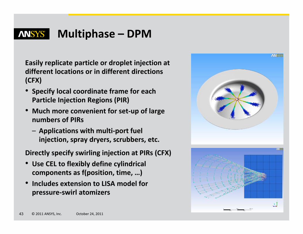
Multiphase – DPM
Easily replicate particle or droplet injection at different locations or in different directions (CFX)• Specify local coordinate frame for each Particle Injection Regions (PIR)
• Much more convenient for set‐up of large numbers of PIRs– Applications with multi‐port fuel injection, spray dryers, scrubbers, etc.
Directly specify swirling injection at PIRs (CFX)• Use CEL to flexibly define cylindrical components as f(position, time, …)
• Includes extension to LISA model for pressure‐swirl atomizers
© 2011 ANSYS, Inc. October 24, 201144
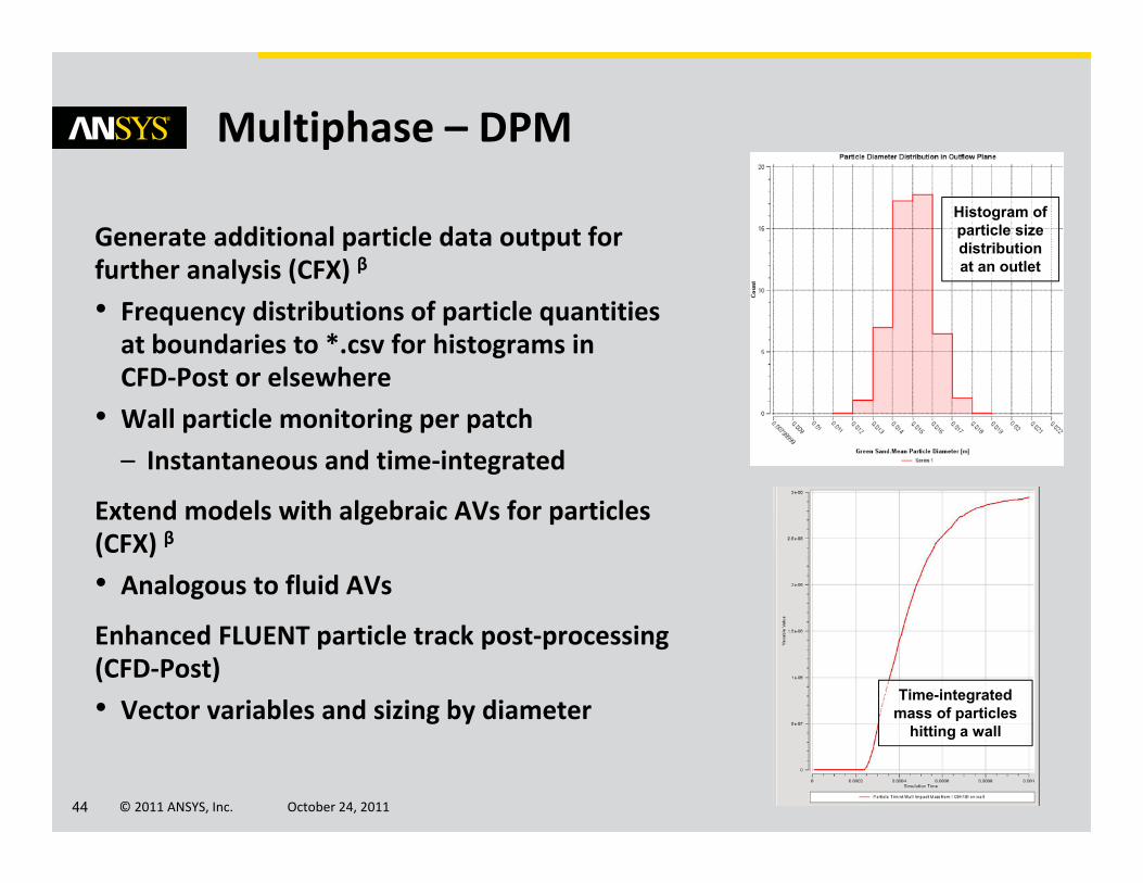
Multiphase – DPM
Generate additional particle data output for further analysis (CFX) β
• Frequency distributions of particle quantities at boundaries to *.csv for histograms in CFD‐Post or elsewhere
• Wall particle monitoring per patch– Instantaneous and time‐integrated
Extend models with algebraic AVs for particles (CFX) β
• Analogous to fluid AVs
Enhanced FLUENT particle track post‐processing (CFD‐Post)• Vector variables and sizing by diameter
Time-integrated mass of particles
hitting a wall
Histogram of particle size distribution at an outlet

© 2011 ANSYS, Inc. October 24, 201145
Multiphase – Condensation
Ability to include global effect of wall condensation without multi‐phase details (CFX)• Single phase, multiple components– Mixture of one condensable and one or more non‐condensable species
• Condensable component extracted by sink terms at walls and CHT boundaries, as function of concentration through boundary layer– Liquid film is not modeled
• Key application: nuclear accident scenarios looking at containment pressure variation over time need to include macroscopic effect of condensation
Water condensation near a wall at a fluid-
solid interface
© 2011 ANSYS, Inc. October 24, 201146
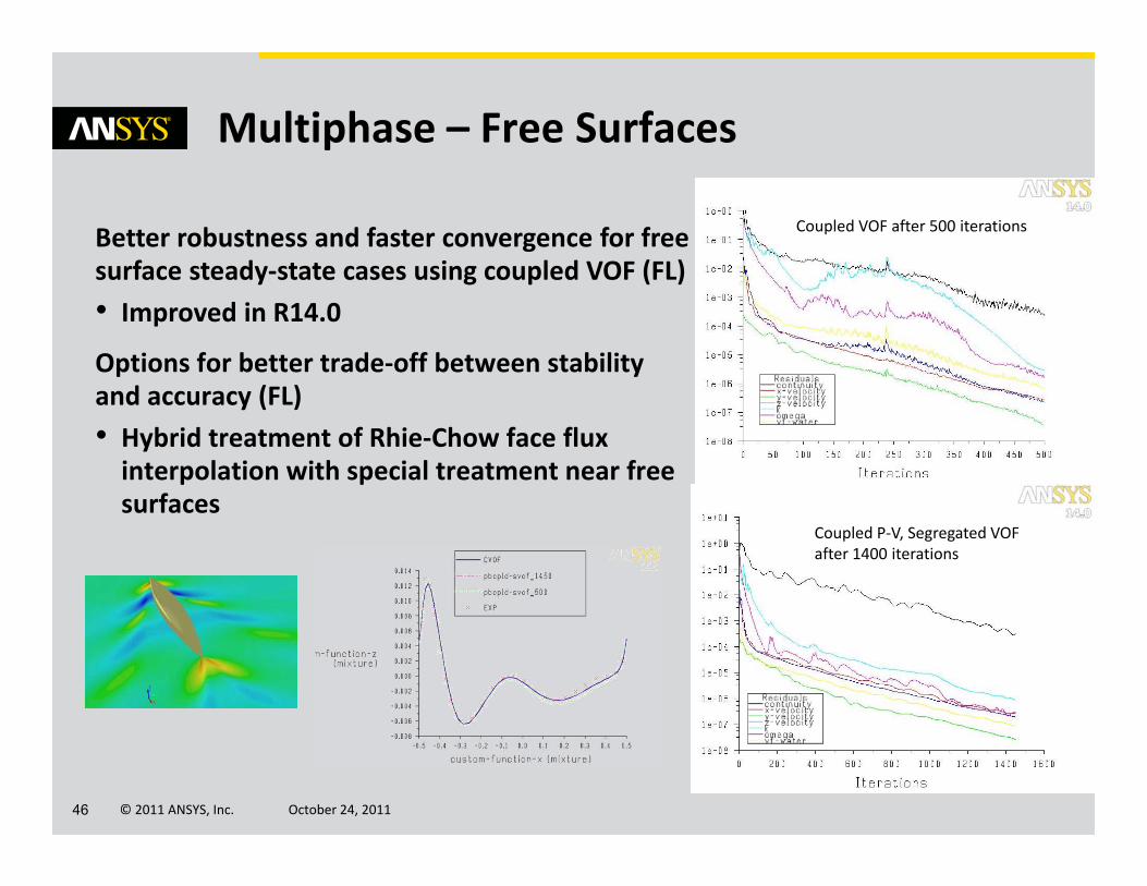
Multiphase – Free Surfaces
Better robustness and faster convergence for free surface steady‐state cases using coupled VOF (FL)• Improved in R14.0
Options for better trade‐off between stability and accuracy (FL)• Hybrid treatment of Rhie‐Chow face flux interpolation with special treatment near free surfaces
Coupled VOF after 500 iterations
Coupled P‐V, Segregated VOF after 1400 iterations
© 2011 ANSYS, Inc. October 24, 201147
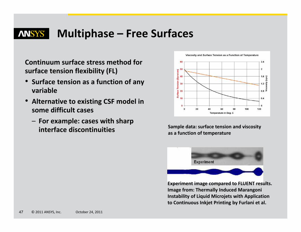
Multiphase – Free Surfaces
Continuum surface stress method for surface tension flexibility (FL)• Surface tension as a function of any variable
• Alternative to existing CSF model in some difficult cases– For example: cases with sharp interface discontinuities Sample data: surface tension and viscosity
as a function of temperature
Experiment image compared to FLUENT results. Image from: Thermally Induced MarangoniInstability of Liquid Microjets with Application to Continuous Inkjet Printing by Furlani et al.
© 2011 ANSYS, Inc. October 24, 201148
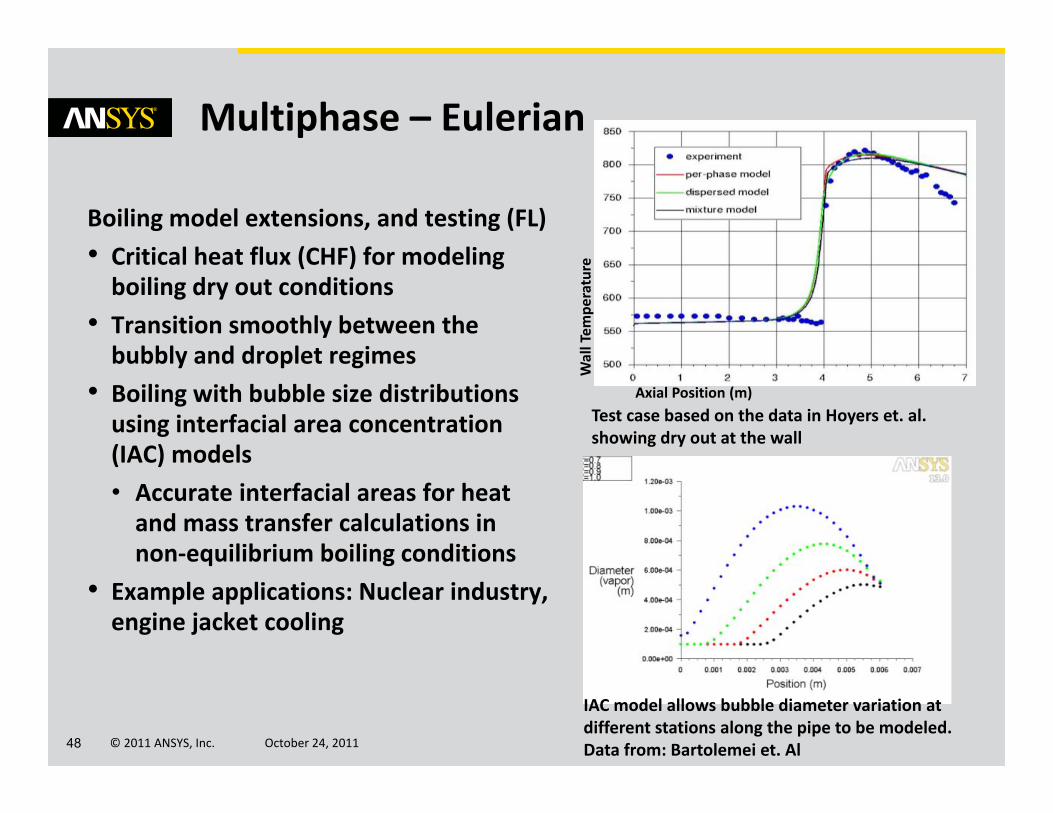
Multiphase – Eulerian
Boiling model extensions, and testing (FL)• Critical heat flux (CHF) for modeling boiling dry out conditions
• Transition smoothly between the bubbly and droplet regimes
• Boiling with bubble size distributions using interfacial area concentration (IAC) models• Accurate interfacial areas for heat and mass transfer calculations in non‐equilibrium boiling conditions
• Example applications: Nuclear industry, engine jacket cooling
Axial Position (m)
Wall Tem
perature
Test case based on the data in Hoyers et. al. showing dry out at the wall
IAC model allows bubble diameter variation at different stations along the pipe to be modeled. Data from: Bartolemei et. Al

© 2011 ANSYS, Inc. October 24, 201149
Multiphase – Eulerian
Combine phase change and varying dispersed phase size distributions for improved accuracy (CFX) β
• Homogeneous and inhomogeneous MuSiG can be applied together with general phase change and RPI wall boiling models
Simulation and comparison with experimental results from DEBORA Test Facility, courtesy of HZDR (formerly FZD)
= +

© 2011 ANSYS, Inc. October 24, 201150
Multiphase – Population Balance
Model diameter and other variable changes (bin fraction, moments) due to density changes in the dispersed phase (FL)• Compressible dispersed phase• Example applications: Geophysical flows, oil and gas flows, compressible flows with population balance
Model growth and nucleation with the inhomogeneous discrete model (FL)• Example applications: Crystallization, bubble columns with mass transfer
Effect of expansion on bubble diameter in bubble column with discrete method: Monodispersedbubbles injected at bottom and results compared with analytical diameter (in white)
© 2011 ANSYS, Inc. October 24, 201151
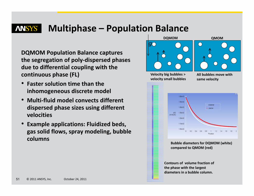
Multiphase – Population Balance
DQMOM Population Balance captures the segregation of poly‐dispersed phases due to differential coupling with the continuous phase (FL) • Faster solution time than the inhomogeneous discrete model
• Multi‐fluid model convects different dispersed phase sizes using different velocities
• Example applications: Fluidized beds, gas solid flows, spray modeling, bubble columns
Velocity big bubbles > velocity small bubbles
All bubbles move with same velocity
DQMOM QMOMg
Bubble diameters for DQMOM (white) compared to QMOM (red)
Contours of volume fraction of the phase with the largest diameters in a bubble column.
© 2011 ANSYS, Inc. October 24, 201152
Multiphase – Eulerian Wall Film
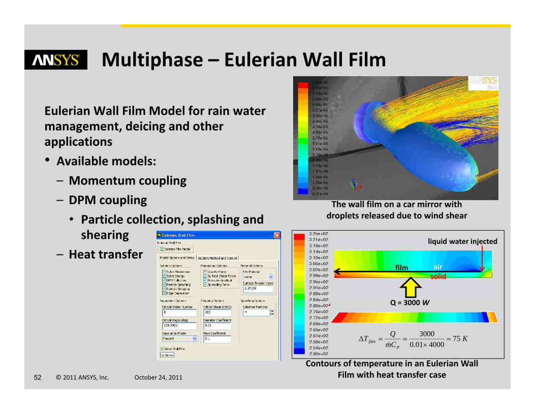
Eulerian Wall Film Model for rain water management, deicing and other applications • Available models:– Momentum coupling– DPM coupling
• Particle collection, splashing and shearing
– Heat transfer
Contours of temperature in an Eulerian Wall Film with heat transfer case
film
Q = 3000 W
airsolid
liquid water injected
KCmQT
Pfilm 75
400001.03000
The wall film on a car mirror withdroplets released due to wind shear
© 2011 ANSYS, Inc. October 24, 201153
Comprehensive CFD Capabilities
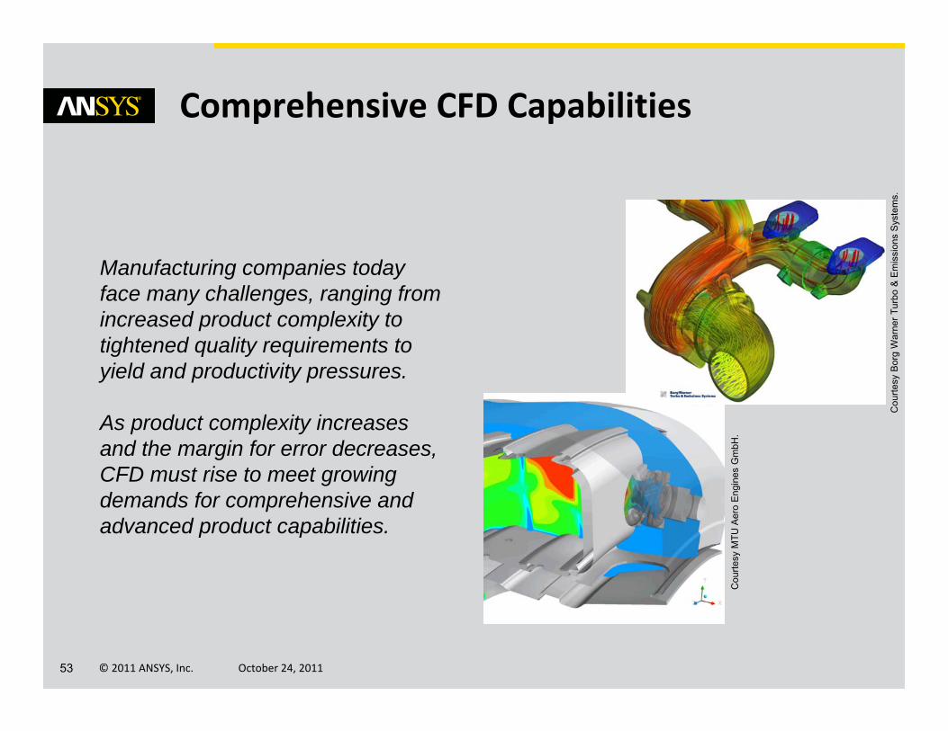
Manufacturing companies today face many challenges, ranging from increased product complexity to tightened quality requirements to yield and productivity pressures.
As product complexity increases and the margin for error decreases, CFD must rise to meet growing demands for comprehensive and advanced product capabilities.
Cou
rtesy
Bor
g W
arne
r Tur
bo &
Em
issi
ons
Sys
tem
s.
Cou
rtesy
MTU
Aer
o E
ngin
es G
mbH
.

© 2011 ANSYS, Inc. October 24, 201154
Comprehensive CFD – Motion
Improved accuracy with simplicity of immersed solids (CFX)• Addition of boundary model for more realistic velocity forcing with immersed solids– Track nodes nearest to immersed solid– Assume constant shear (laminar) or use scalable wall function (turbulent) to modify forcing at immersed solid ‘wall’
• Can improve immersed solid predictions significantly– Continuing development for further improvements and broader applications
Boundary-fitted mesh
Immersed Solid (default)
Immersed Solid with Boundary Model

© 2011 ANSYS, Inc. October 24, 201155
Comprehensive CFD – Motion
Further user control on deforming mesh to allow retention of optimal mesh quality (CFX) β
• Diffusion of boundary mesh motion can be defined to be anisotropic – i.e. preferential diffusion in different directions
Sample case: Deformation of an originally square domain xy xy
Final mesh with isotropic diffusion: skewed elements
Final mesh with anisotropic diffusion: improved mesh quality, greater range of motion possible

© 2011 ANSYS, Inc. October 24, 201156
Comprehensive CFD – Interfaces
Easy simulation of opening and closing (CFX)• Conditional GGIs that can open and close as the solution progresses
• Define condition as CEL function of solution– e.g. After set time, based on solution values (single or integral values)
• Example applications– Membranes bursting, windows shattering, valves opening/closing
• Define as reversible (e.g. valve) or irreversible (e.g. burst membrane)

© 2011 ANSYS, Inc. October 24, 201157
Comprehensive CFD – Dynamic Mesh
Greater accuracy and speed with default interface settings (CFX)• Direct intersection method is now default – Significantly faster
• biggest impact on transient cases with re‐intersections
– More accurate than bitmap method
Support for dynamic mesh on meshes with polyhedral elements (FL)• Smoothing on polyhedral elements • Polyhedral elements skipped during remeshing
© 2011 ANSYS, Inc. October 24, 201158
Comprehensive CFD – Turbulence
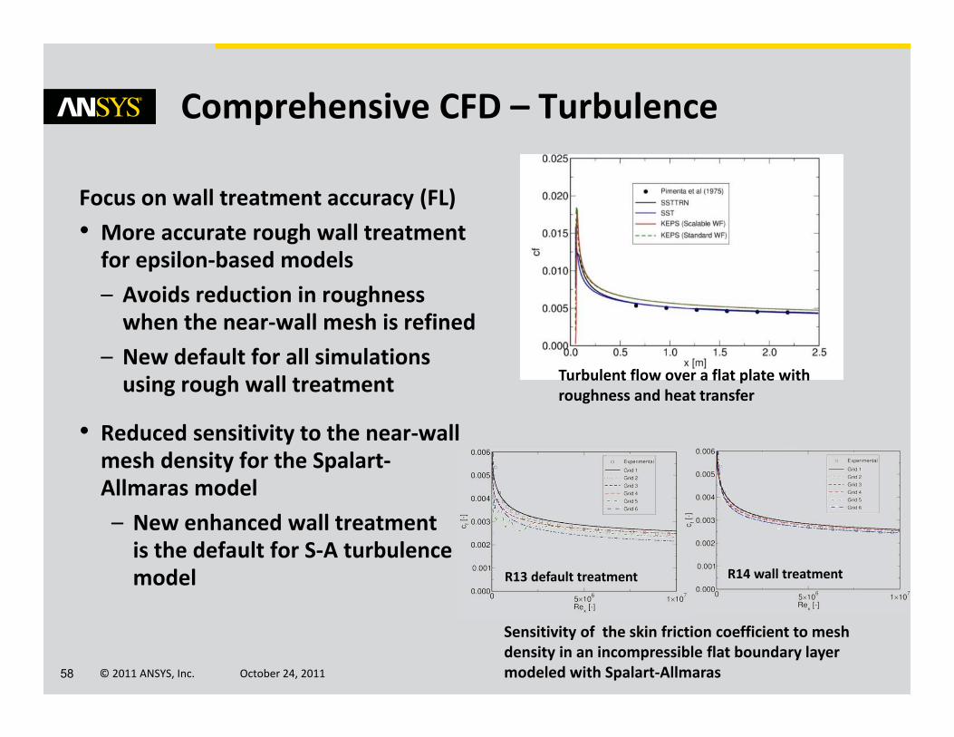
Focus on wall treatment accuracy (FL)• More accurate rough wall treatment for epsilon‐based models – Avoids reduction in roughness when the near‐wall mesh is refined
– New default for all simulations using rough wall treatment
• Reduced sensitivity to the near‐wall mesh density for the Spalart‐Allmaras model– New enhanced wall treatment is the default for S‐A turbulence model
Turbulent flow over a flat plate with roughness and heat transfer
R14 wall treatment R13 default treatment
Sensitivity of the skin friction coefficient to mesh density in an incompressible flat boundary layer modeled with Spalart‐Allmaras
© 2011 ANSYS, Inc. October 24, 201159
Comprehensive CFD – Turbulence
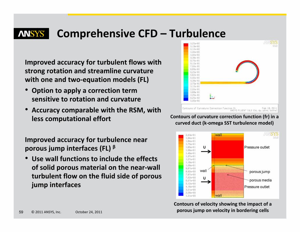
Improved accuracy for turbulent flows with strong rotation and streamline curvature with one and two‐equation models (FL)• Option to apply a correction term sensitive to rotation and curvature
• Accuracy comparable with the RSM, with less computational effort
Improved accuracy for turbulence near porous jump interfaces (FL) β
• Use wall functions to include the effects of solid porous material on the near‐wall turbulent flow on the fluid side of porous jump interfaces
Contours of curvature correction function (fr) in a curved duct (k‐omega SST turbulence model)
Contours of velocity showing the impact of a porous jump on velocity in bordering cells

© 2011 ANSYS, Inc. October 24, 201160
Comprehensive CFD – Turbulence
More accurate solution of high Re wall bounded flows using LES (FL)• Algebraic Wall Modeled LES (WMLES) formulation based on Smagorinsky model
• Benefits gas turbine combustors and other internal flow applications
Apply scale‐resolving turbulence models only locally, as required, to balance cost vs. accuracy (CFX) β
• Zonal LES model using turbulence forcing
• Forcing zone defined by logical CEL function
Flow over a wall mounted hump
Contours of Q criterion
A mixing layer with resolved turbulence using SAS initiated by the forcing model

© 2011 ANSYS, Inc. October 24, 201161
Comprehensive CFD – Acoustics
Validations and model extensions (FL)• Convective effect for FW‐H acoustics solver– Option to include the effect of far‐field velocity on the generated sound for the Ffowcs‐Williams & Hawkins solver
– Improves accuracy when modeling aeroacoustics and external flows
• Model Doppler effects due to the relative motion of acoustic sources and receivers (FL)– For example: Sound from a source moving with a constant speed (airplane, car)
M=0.2
FWH source surface,R=1m
Receivers, R=3m
2D monopole with convection
OASPL – overall sound pressure level
M=0.4Moving receiver
SourceSound pressure compared with analytic solution at approach and departure (Doppler effect different frequencies)
Acoustics directivity

© 2011 ANSYS, Inc. October 24, 201162
2x2 3x3 6x6
Serial/Old 218.63 s 269.95s 536.32s
Serial/New 202.40s 241.56s 429.40s
Parallel 2‐proc/Old
86.4s 107.4s 205.3s
Parallel 2‐proc/New
80.7s 98.4s 167.2s
Comprehensive CFD – Radiation
More Efficient Discrete Ordinates Radiation (FL)• DO radiation calculations ignore solid zones not participating in radiation or participating in heat transfer by conduction only
• Avoids unnecessary CPU time and memory allocations• Performance improvement varies depending on specifics of case– Up to 20% improvement for test cases
Sample data for a 3D case with 5 solid zones
© 2011 ANSYS, Inc. October 24, 201163
Comprehensive CFD – Shell Conduction
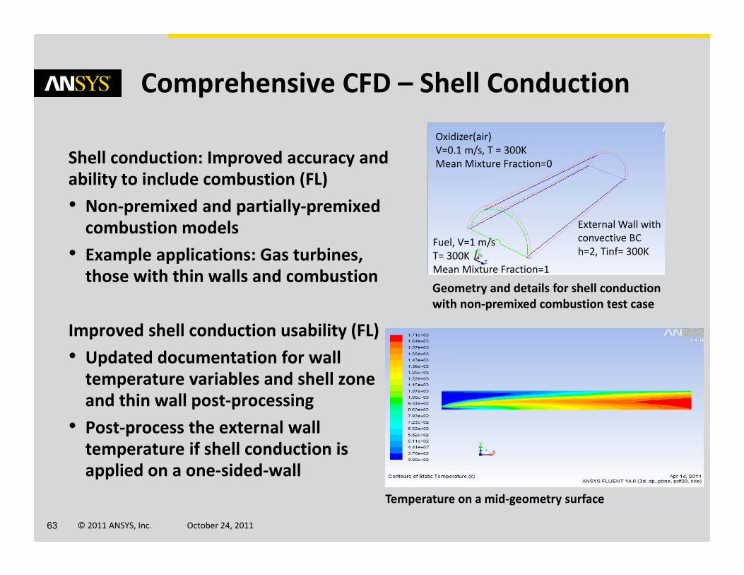
Shell conduction: Improved accuracy and ability to include combustion (FL)• Non‐premixed and partially‐premixed combustion models
• Example applications: Gas turbines, those with thin walls and combustion
Improved shell conduction usability (FL)• Updated documentation for wall temperature variables and shell zone and thin wall post‐processing
• Post‐process the external wall temperature if shell conduction is applied on a one‐sided‐wall
Oxidizer(air)V=0.1 m/s, T = 300KMean Mixture Fraction=0
Fuel, V=1 m/sT= 300KMean Mixture Fraction=1
External Wall with convective BCh=2, Tinf= 300K
Temperature on a mid‐geometry surface
Geometry and details for shell conduction with non‐premixed combustion test case

© 2011 ANSYS, Inc. October 24, 201164
1D Reacting Channel Model (FL)• Detailed chemistry in the channel (plug flow)– Simple geometry, complex chemistry
• 3D heat transfer in the furnace/shell – Complex geometry,simple (or no) chemistry
• Example applications: cracking furnace, fuel reformers, …
Comprehensive CFD – Reacting Flows
1D reacting channel model in FLUENT
1D reacting channel geometry in FLUENT
© 2011 ANSYS, Inc. October 24, 201165
Comprehensive CFD – Reacting Flows
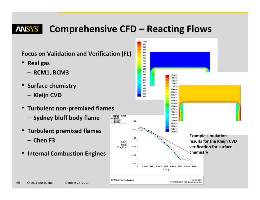
Focus on Validation and Verification (FL)• Real gas – RCM1, RCM3
• Surface chemistry – Kleijn CVD
• Turbulent non‐premixed flames – Sydney bluff body flame
• Turbulent premixed flames– Chen F3
• Internal Combustion Engines
Example simulation results for the Kleijn CVD verification for surface chemistry

© 2011 ANSYS, Inc. October 24, 201166
Comprehensive CFD – Combustion
More accurate, flexible, and efficient combustion simulations with CFX‐RIF (CFX) β
• Variable thermodynamic conditions• User‐defined mechanisms• Reduced materials list
Expanded modeling with inert residual material model (CFX) β
• Application example: Safety analyses involving hydrogen combustion together with fire suppression using water

© 2011 ANSYS, Inc. October 24, 201167
Comprehensive CFD – Combustion
Faster, more accurate, and more general unsteady combustion (CFX) β
• G‐equation model upgrade– GUI exposure– Robustness enhancement– Additional correlations for flame speed and flame thickness
– Improved compatibility with ignition models
– More accurate and faster flame front re‐initialization
Easy customization of non‐ideal mixture properties (CFX) β
Flame front prediction from G-equation shortly after ignition in an IC engine

© 2011 ANSYS, Inc. October 24, 201168
The polymer, glass, metals and cement processing industries face the special challenge of highly complex material behaviour when performing simulations to minimize physical prototyping in the manufacture of extrusion dies or improve the quality of thermoformed or blown products.
Importantly, for say the packaging industry, is the ability to predict more accurately the structural performance of the package in real-use scenarios.
ANSYS Polyflow provides a host of special material models and enhanced capabilities to meet these needs.
Special Material Processing
© 2011 ANSYS, Inc. October 24, 201169
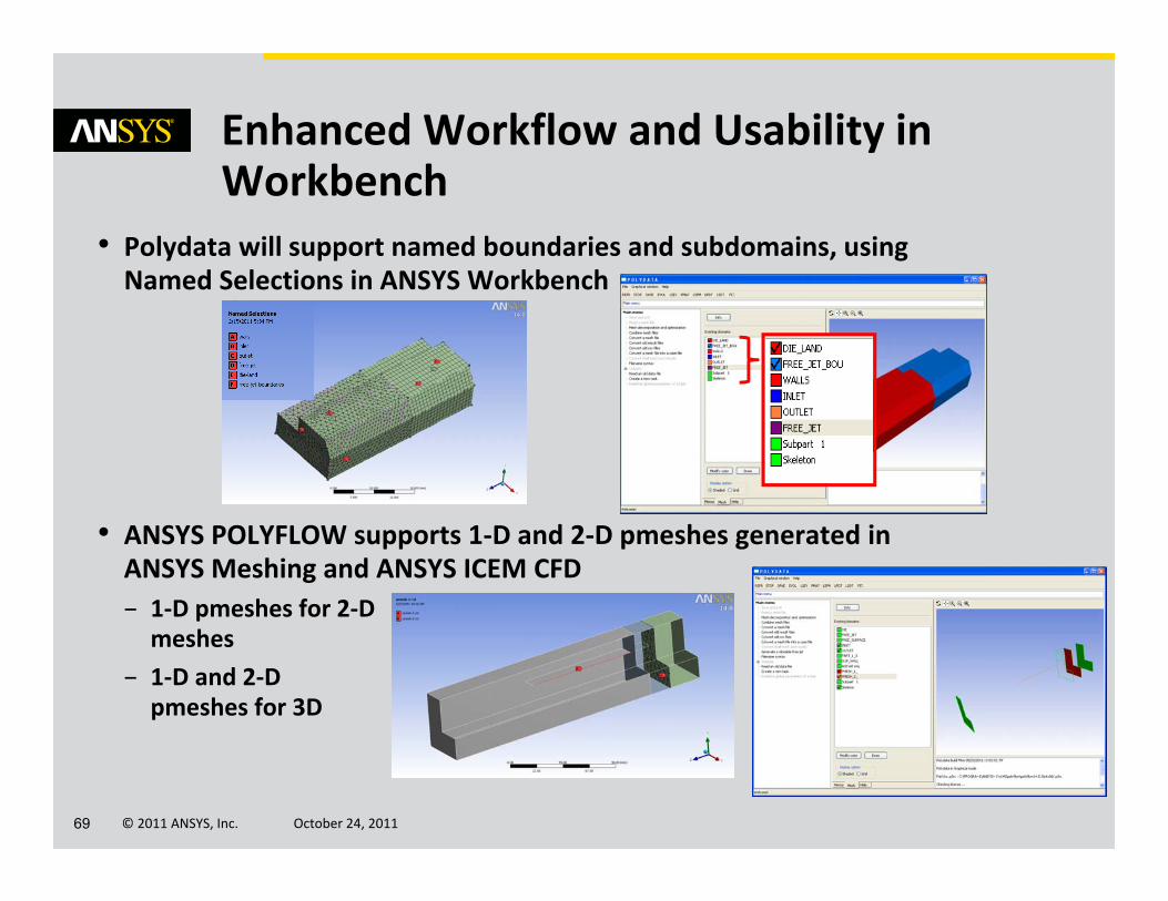
• Polydata will support named boundaries and subdomains, using Named Selections in ANSYS Workbench
• ANSYS POLYFLOW supports 1‐D and 2‐D pmeshes generated in ANSYS Meshing and ANSYS ICEM CFD– 1‐D pmeshes for 2‐D meshes
– 1‐D and 2‐D pmeshes for 3D
Enhanced Workflow and Usability in Workbench

© 2011 ANSYS, Inc. October 24, 201170
• A database is now available of ANSYS Workbench Project Templates for common applications of ANSYS Polyflow– Templates folder in the POLYFLOW 14.0 installation
• Each project contains a complete calculation (Geometry to Post‐processing) with parameters and a final report– Blow‐molding, extrusion, thermoforming examples in ANSYS Workbench archived (.wbpz) format
• The template projects can be used for learning purposes or as starting points for individual projects.
Enhanced Usability in Workbench from Templates
© 2011 ANSYS, Inc. October 24, 201171
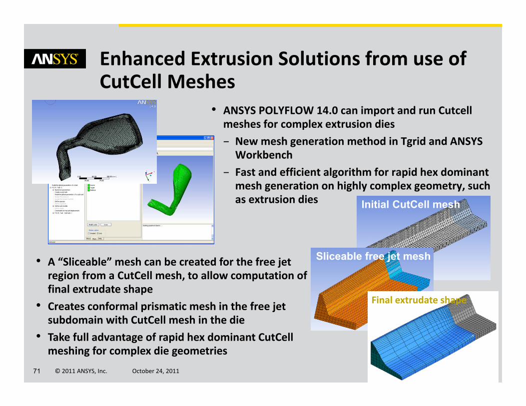
• ANSYS POLYFLOW 14.0 can import and run Cutcellmeshes for complex extrusion dies– New mesh generation method in Tgrid and ANSYS Workbench
– Fast and efficient algorithm for rapid hex dominant mesh generation on highly complex geometry, such as extrusion dies
Enhanced Extrusion Solutions from use of CutCell Meshes
• A “Sliceable” mesh can be created for the free jet region from a CutCell mesh, to allow computation of final extrudate shape
• Creates conformal prismatic mesh in the free jet subdomain with CutCell mesh in the die
• Take full advantage of rapid hex dominant CutCellmeshing for complex die geometries
Initial CutCell mesh
Sliceable free jet mesh
Final extrudate shape
© 2011 ANSYS, Inc. October 24, 201172
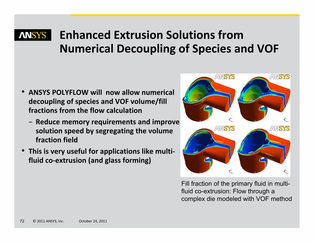
• ANSYS POLYFLOW will now allow numerical decoupling of species and VOF volume/fill fractions from the flow calculation– Reduce memory requirements and improve solution speed by segregating the volume fraction field
• This is very useful for applications like multi‐fluid co‐extrusion (and glass forming)
Enhanced Extrusion Solutions from Numerical Decoupling of Species and VOF
Fill fraction of the primary fluid in multi-fluid co-extrusion: Flow through a complex die modeled with VOF method

© 2011 ANSYS, Inc. October 24, 201173
• A force can be specified for mold motion with shell meshes for parisons in blow molding and thermoforming
• Specify maximum displacement of the mold to set a bounding criterion for the motion
Enhanced Solutions for Blow Molding and Thermoforming
• A new contact release method has been implemented for blow molding and thermoforming
• This allows determination of Parison “peeling” from mold for blow molding and plug release in thermoforming
• Contact release is compatible with both specified force and specified velocity for the mold
Thermoforming of a medical blister

© 2011 ANSYS, Inc. October 24, 201174
• Thickness data from ANSYS POLYFLOW can be sent to ANSYS Mechanical and ANSYS Explicit Dynamics via an automatic connection
• Complete Virtual Prototyping and Testing capability in ANSYS Workbench for packaging manufacturing:– Simulate blow molding or thermoforming process to get final thickness distribution with Polyflow
– Based on Polyflow predicted variable thickness, perform stress and deformation analysis• Top load stress analysis with ANSYS Mechanical shown here
Virtual Prototyping for Packaging Applications ‐Mechanical

© 2011 ANSYS, Inc. October 24, 201175
• Where the deformation or loading rate are larger, then transfer the Polyflow thickness data to Explicit Dynamics system in Workbench– Explicit Dynamics is available as part of ANSYS Explicit STR and ANSYS AUTODYN
• Here we will load a blown part (created from Polyflow) with a rigid plate (in green in mesh plot)– Loading normal to the plate
Virtual Prototyping for Packaging Applications – Explicit Dynamics

© 2011 ANSYS, Inc. October 24, 201176
ANSYS Fluid Dynamics 14 contains enhancements in all products…• ANSYS FLUENT, ANSYS CFX, ANSYS CFD‐Post• ANSYS Turbogrid• ANSYS Polyflow
… for rapid and robust meshing, workflow and usability, HPC and solver speed, rotating machinery, automotive and multiphase applications as well as overall to provide comprehensive CFD.
Summary

© 2011 ANSYS, Inc. October 24, 201177
Questions?
© 2011 ANSYS, Inc. October 24, 201178
Appendix
© 2011 ANSYS, Inc. October 24, 201179
Workflow & Usability – ANSYS CFD
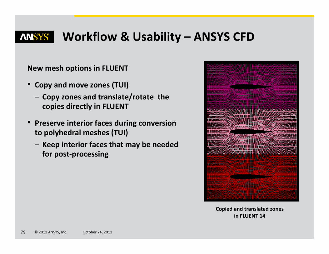
New mesh options in FLUENT
• Copy and move zones (TUI)– Copy zones and translate/rotate the copies directly in FLUENT
• Preserve interior faces during conversion to polyhedral meshes (TUI) – Keep interior faces that may be needed for post‐processing
Copied and translated zones in FLUENT 14
© 2011 ANSYS, Inc. October 24, 201180
FLUENT 14 Solver Numerics
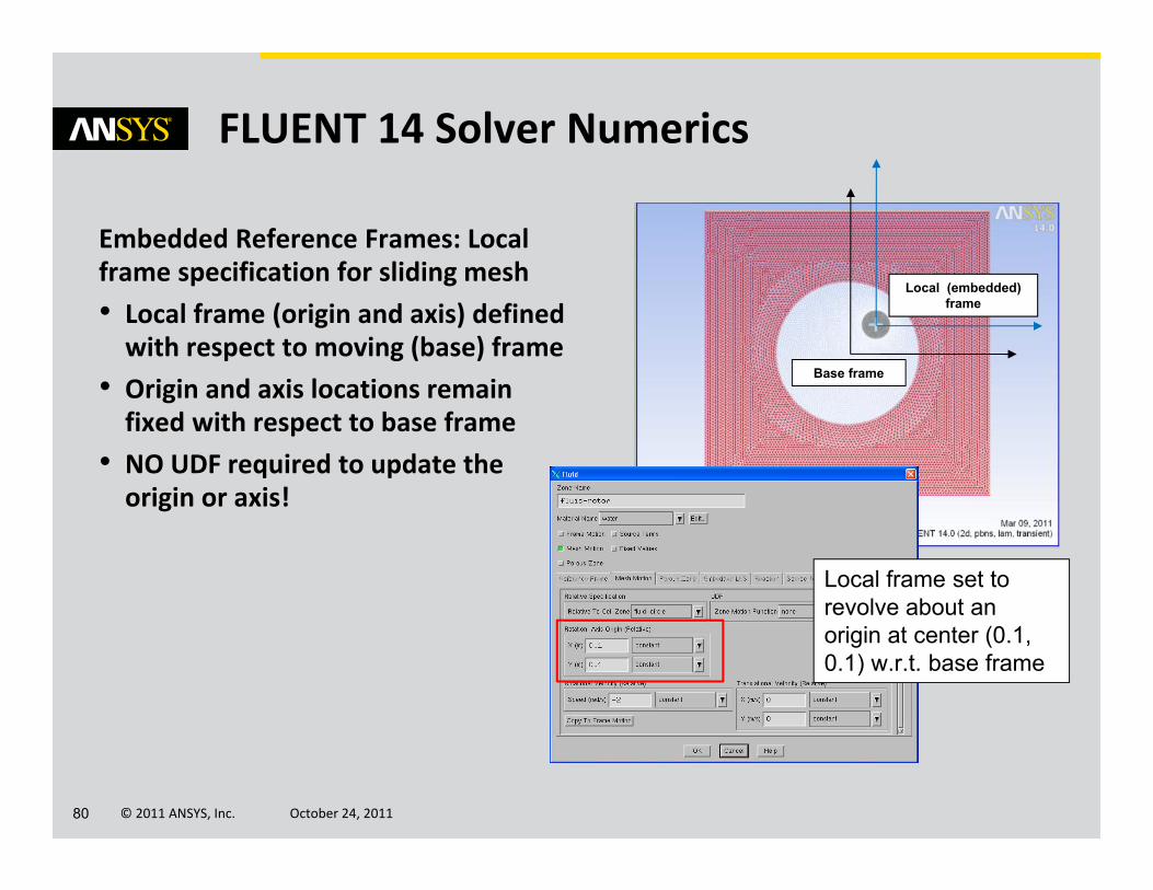
Embedded Reference Frames: Local frame specification for sliding mesh• Local frame (origin and axis) defined with respect to moving (base) frame
• Origin and axis locations remain fixed with respect to base frame
• NO UDF required to update the origin or axis!
Local (embedded) frame
Base frame
Local frame set to revolve about an origin at center (0.1, 0.1) w.r.t. base frame
© 2011 ANSYS, Inc. October 24, 201181
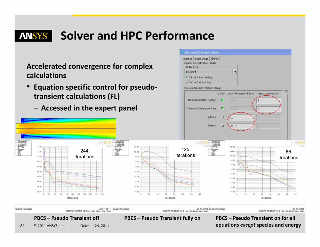
Solver and HPC Performance
Accelerated convergence for complex calculations• Equation specific control for pseudo‐transient calculations (FL)– Accessed in the expert panel
PBCS – Pseudo Transient off PBCS – Pseudo Transient fully on PBCS – Pseudo Transient on for all equations except species and energy
244 iterations
125iterations
66iterations

© 2011 ANSYS, Inc. October 24, 201182
Solver and HPC Performance
Work in Progress: GPU investigation• Acceleration limited to Jacobi/Gauss‐Seidel smoothers in the context of flexible cycle on fine level
• Special interleaved CSR matrix storage structures for faster memory access on GPUs
• Coloring algorithm for parallelizing Gauss‐Seidel on GPU
R14: Viewfactor calculations on GPUs as beta (FLUENT)
Research continues…
X X X X X
X X X X X
X X X X X X
X X X X X
X X X X X X
X X X X X
X X X X X X
X X X X X X
X X X X X X X
X X X X X

© 2011 ANSYS, Inc. October 24, 201183
Multiphase – Eulerian
Improved numerical stability for user‐defined mass transfer with compressible phases (FL) • Linearized option for user defined mass transfer also allows larger timesteps
New Hulin‐Gidaspow and Gibilaro drag laws for granular flows (FL)• Modified Huilin‐Gidaspow drag allows smooth transition from dilute to dense limit, improving numerical behavior
• Gibilaro drag law for fluidized beds provides a better representation of physics in these cases
Cavitation in a nozzle using linearized mass transfer
vof of liquid
Absolute pressure
© 2011 ANSYS, Inc. October 24, 201184
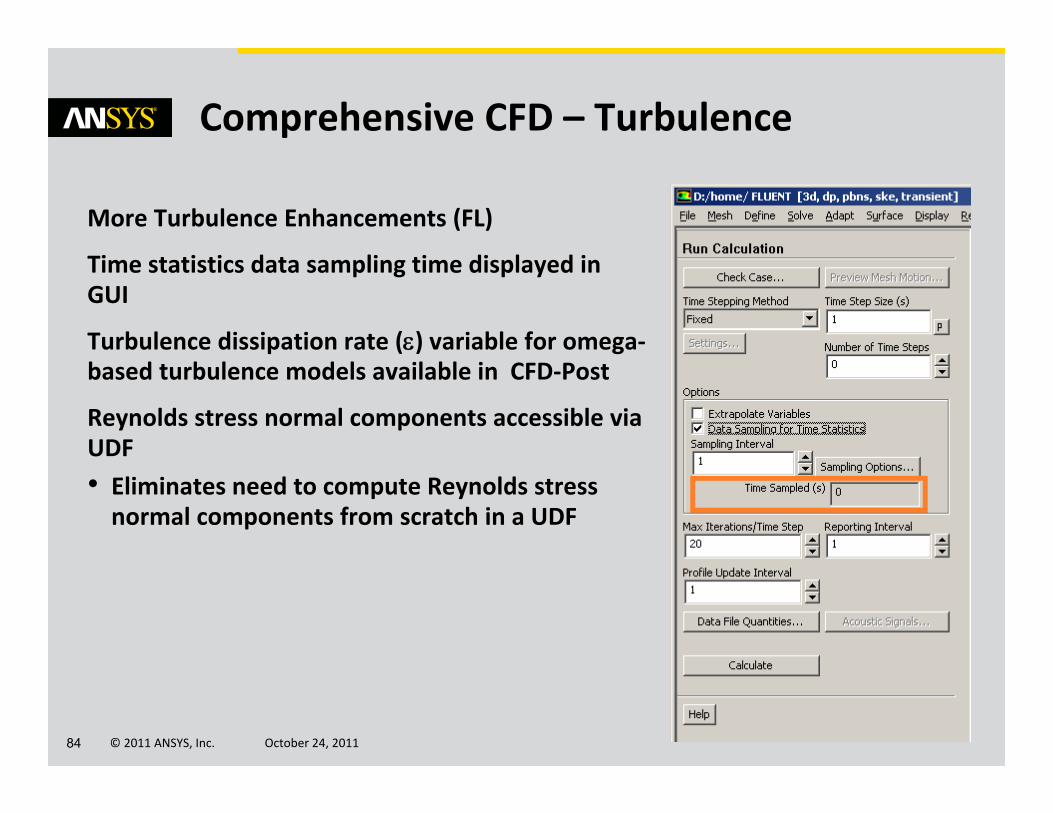
Comprehensive CFD – Turbulence
More Turbulence Enhancements (FL)
Time statistics data sampling time displayed in GUI
Turbulence dissipation rate () variable for omega‐based turbulence models available in CFD‐Post
Reynolds stress normal components accessible via UDF• Eliminates need to compute Reynolds stress normal components from scratch in a UDF
© 2011 ANSYS, Inc. October 24, 201185
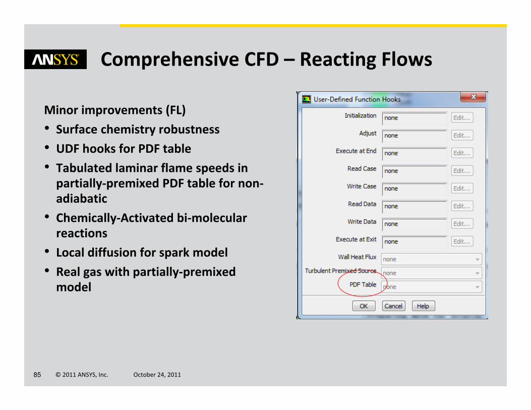
Comprehensive CFD – Reacting Flows
Minor improvements (FL)• Surface chemistry robustness• UDF hooks for PDF table• Tabulated laminar flame speeds in partially‐premixed PDF table for non‐adiabatic
• Chemically‐Activated bi‐molecular reactions
• Local diffusion for spark model• Real gas with partially‐premixed model
© 2011 ANSYS, Inc. October 24, 201186
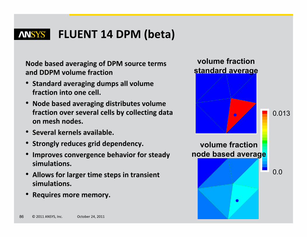
FLUENT 14 DPM (beta)
Node based averaging of DPM source terms and DDPM volume fraction • Standard averaging dumps all volume fraction into one cell.
• Node based averaging distributes volume fraction over several cells by collecting data on mesh nodes.
• Several kernels available.• Strongly reduces grid dependency.• Improves convergence behavior for steady simulations.
• Allows for larger time steps in transient simulations.
• Requires more memory.
0.013
0.0
volume fractionstandard average
volume fractionnode based average

© 2011 ANSYS, Inc. October 24, 201187
Rotating Machinery
Time Transformation
• Solve in transformed ‘inclined’ time, fully implicit, with turbulence
• Results in inclined time stored using Fourier‐based data compression
• Results re‐constructed in physical time for analysis
Fourier Transformation
• Fourier–series used for reconstruction of solution history on pitch‐wise boundary and inter‐row interfaces for efficient data storage & convergence
• Two passages for better signal collection and faster convergence than single passage