ansys v14 udt s iupdate seminar - caeai.com v14 udt s iupdate seminar ... • rigid body dynamics...
TRANSCRIPT

ANSYS v14 U d t S iUpdate Seminar
CAE Associates Inc. and ANSYS Inc. Proprietary© 2012 CAE Associates Inc. and ANSYS Inc. All rights reserved.

V14 Update Seminar Agenda. 8:30 Introduction8 45 G t I t f
1:00 ANSYS CFD2 15 Fl id St t I t ti8:45 Geometry Interfaces
9:15 Meshing• Structural• Fluid
2:15 Fluid Structure Interaction2:30 Break2:45 High Performance Computing3 00 V i l A li iFluid
10:00 Break10:15 Mechanical Updates
• Shell body cyclic symmetry
3:00 Vertical Applications• nCode Design Life• ANSYS Composite Prep/post• Engineering Knowledge Manager
• Contact• External Data Mapping• Named Selection Tools• FE model exposure
4:00 Mechanical APDL• Contact• 3D rezoning• DynamicsFE model exposure
• Postprocessing• Design Assessment• Linear Dynamics• Rigid Body Dynamics
• Dynamics• Materials and Fracture• Radiation• Documentation
• Rigid Body Dynamics• Explicit Dynamics• Remote Solve Manager
11:30 Parametric Modeling
2www.caeai.com
12:00 Lunch

New CAE Associates Employee
Welcome Andy Hughes to the CAE Associates team as the new Accounts Manager!
3www.caeai.com
Geometry C tiConnections
CAE Associates Inc. and ANSYS Inc. Proprietary© 2012 CAE Associates Inc. and ANSYS Inc. All rights reserved.

Geometry Updates
New Geometry readers enable reading a parent CAD file without the need New Geometry readers enable reading a parent CAD file without the need for a CAD system installation on the analysis station.
Note: as a Reader connection there is no parametric association with the original CAD fileoriginal CAD file.
Geometry Interface Name Plug-in Capability
Reader Capability
ANSYS Geometry Interface for Creo Parametric (ProEngineer)
X X (v13)(ProEngineer)
ANSYS Geometry Interface for NX X X (New)
ANSYS Geometry Interface for Autodesk (Inventor/MDT)
X X (New – Inventor and DWG)
ANSYS Geometry Interface for SolidWorks X X (New)y ( )
CADNEXUS/CAPRI CAE Gateway for CATIA V5 X
ANSYS Geometry Interface for Solid Edge X
ANSYS Geometry Interface for CreoElements/Direct Modeling (CoCreate Modeling )
Xg ( g )
ANSYS Geometry Interface for CATIA V5 X
ANSYS Geometry Interface for JT X
ANSYS Geometry Interface for SAT X
5www.caeai.com
ANSYS Geometry Interface for Parasolid X
ANSYS Geometry Interface for Teamcenter X

Geometry Updates
DesignModeler DesignModeler— Usability
• “Hot Key” shortcuts. • edge and vertex visibilityedge and vertex visibility• Thickness display (color)• Auto Freeze for slicing. • Direct Entity input (base objects for operations)• Named Selection Export replaces NS prefix (ala Coodinate system export method).
— Feature• Rotor shaft feature (txt file input)• Mid surface matching tolerance for imperfect offsets
— Electronics• Ice Pack body recognition• Inter operability with ANSOFT• Inter-operability with ANSOFT
6www.caeai.com

DesignModeler Usability
“Hot Key” shortcuts: Hot Key shortcuts: — F3: Apply— F4: Cancel
F6: Toggle display (shaded+edges/shaded/wireframe)— F6: Toggle display (shaded+edges/shaded/wireframe)— F7: Zoom to Fit— Ctrl-A: Select All
Ctrl P: Toggle Point selection filter— Ctrl-P: Toggle Point selection filter— Ctrl-E: Toggle Edge selection filter— Ctrl-F: Toggle Face selection filter
Ctrl B: Toggle Body selection filter— Ctrl-B: Toggle Body selection filter Sketching mode only
— Ctrl-Z: UndoCt l Y R d— Ctrl-Y: Redo
— Ctrl-C: Copy— Ctrl-X: Cut
C l V P
7www.caeai.com
— Ctrl-V: Paste

DesignModeler Usability
Edge and vertex visibility from the View menu Edge and vertex visibility from the View menu.
8www.caeai.com

DesignModeler Usability
Thickness display (color) Thickness display (color)
9www.caeai.com

DesignModeler Usability
Freezing no longer required for slice operations: Freezing no longer required for slice operations: — For Create > Slice and “Slice Material” modeling operations. — Frozen status is invoked as part of the slicing operation.
Active body
Frozen body result
10www.caeai.com
DesignModeler Usability
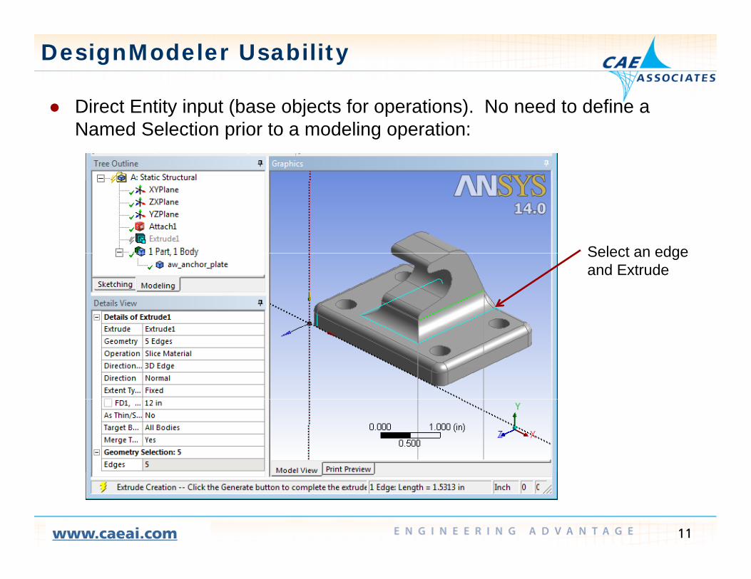
Direct Entity input (base objects for operations) No need to define a Direct Entity input (base objects for operations). No need to define a Named Selection prior to a modeling operation:
Select an edgeSelect an edge and Extrude
11www.caeai.com

DesignModeler Usability
Named Selection Export replaces NS prefix (ala Coordinate system export Named Selection Export replaces NS prefix (ala Coordinate system export method).
12www.caeai.com

DesignModeler Usability
Shaft Import from a text file for Rotor Dynamics models Shaft Import from a text file for Rotor Dynamics models
13www.caeai.com

DesignModeler Usability
Electronics Toolbar Electronics Toolbar— Ice Pack body recognition— Display of IcePak icons for IcePak bodies in the feature tree
Part structure transfer to IcePak— Part structure transfer to IcePak— Ability to rename multiple bodies in a single step for easy organization
14www.caeai.com

Improved Interoperability with Ansoft
• Bi-directional geometry transfer between Ansoft products and Workbench• Bi-directional geometry transfer between Ansoft products and Workbench applications for multi-physics simulations.
15www.caeai.com
SpaceClaim Direct Modeler
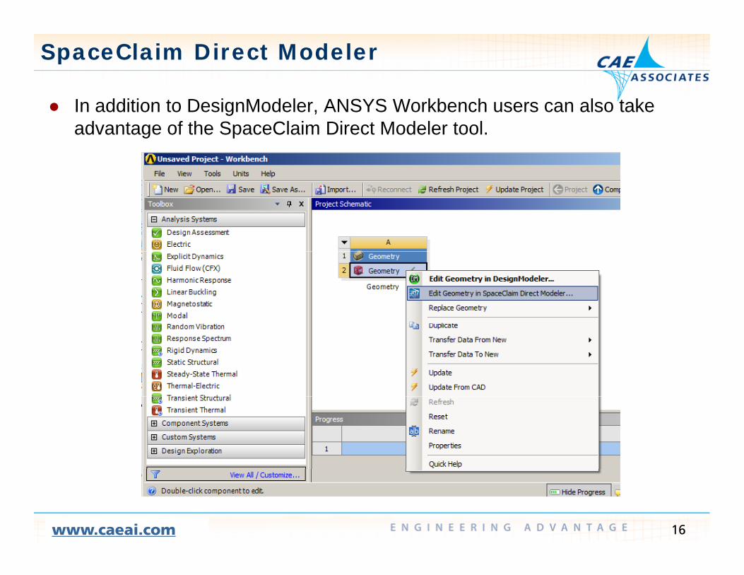
In addition to DesignModeler ANSYS Workbench users can also take In addition to DesignModeler, ANSYS Workbench users can also take advantage of the SpaceClaim Direct Modeler tool.
16www.caeai.com

SpaceClaim Direct Modeler
Geometry modifications are done interactively in SpaceClaim using Geometry modifications are done interactively in SpaceClaim using operations like Pull, Fill, and Move.
17www.caeai.com

ANSYS Geometry Tools
CAD System (ProE,NX,SolidWorks,SolidEdge,Inventor,CATIA, etc.)
Geometry Plugin(geometry and CAD parameters)
Geometry Import(geometry only)
D i M d lDesignModeler SpaceClaim Direct Modeler
Geometry +
Geometry ++
CAD and DM parameters
+ SpaceClaimparameters
Mechanical
18www.caeai.com

SpaceClaim v14 Updates
SpaceClaim SpaceClaim— Improved Integration with WB— Enhanced Model Preparation Tools
• Preview of Topology Sharing• Preview of Topology Sharing• Improvements in Volume Extraction/Creation• New selection and repair options
— Video tutorials can be found on the CAEA website at: http://www.caeai.com/engineering-training-ansys-downloads-
details.php?webinar=ANSYS+SpaceClaim+Direct+Modeler+Webinar+-+Web+Based&webinarID=29
— And on the SpaceClaim website at: http://www.spaceclaim.com/en/Support/Tutorials/Essentials.aspx
19www.caeai.com

ANSYS Modeling Tools
DesignModeler SpaceClaimg pGeometry connection • “Plugins” read the parent CAD file.
• bi-directionally associative connection.• Persistent geometry tags.• Automatic model update.
• CAD Translators import geometry (no shared CAD parameters).
• CAD program is not needed to import geometry.
• No additional licensing is requiredNo additional licensing is required.
SolidModeling • Feature Based Approach. • Quick learning curve.• All features are parametric. • Robust updating of CAD geometry.
• Direct modeling.• Not limited by the CAD tool “trail” or design
intent. Works directly on imported geometry.
Defeaturing • Defeaturing operations are “features” in the model history. Deleted features can be recovered.
• Variety of repair options with (automatic and user controlled).
• Undo/Redo buffer for the active database only.
• Search for features of similar size or range.
Simplification • Automatic Face pairing and shell thickness assignment.
• Automatic extension for shell body intersections.
• Thin Surface tool for extracting 2D cross
• Face pairing by body thickness. • Automatic extension for shell body
intersections.• Beam cross section extraction from
solid bodies. gsections.
Parameter Management • Shared parameters with the CAD program and the analysis tool.
• Filter out of unnecessary parameters. • Parameter associations between CAD and
• Users are free to pull, move, fill etc in SCDM unhampered by CAD modeling history or feature dependencies.
• Shared parameters with the analysis
20www.caeai.com
Parameter associations between CAD and DM.
• Robust parametric regeneration.
Shared parameters with the analysis tool only.

Meshing - Mechanical
CAE Associates Inc. and ANSYS Inc. Proprietary© 2012 CAE Associates Inc. and ANSYS Inc. All rights reserved.

Meshing - Mechanical v14 “Direct” now named “Selective” meshing.
— Worksheet captures body order for Selective meshing (demo). — Named selections are created and sent to the solver (element components).
Note: The automatic method is still used for mixed order meshing of parts.
22www.caeai.com

Meshing - Mechanical v14
For convenience you can “dock” the Worksheet window in two steps For convenience you can dock the Worksheet window in two steps (separate it from the main graphics window).
Grab the Worksheet tab at the bottom of the screen and drop it on the docking location of choicedocking location of choice.
23www.caeai.com

Meshing - Mechanical v14
Shell Meshing Shell Meshing — Supports additional methods (default (free) versus uniform quad/tri). — Supports Selective Meshing.
Supports Cyclic Symmetry (matched boundary meshes)— Supports Cyclic Symmetry (matched boundary meshes).
Default quad/tri
Uniform quad/tri
Mesh connections
24www.caeai.com

Meshing - Mechanical v14
Shell Mesh Connections (introduced at v13) Shell Mesh Connections (introduced at v13)— Occur at the mesh level (do not require geometry modification to close gaps). — Connections are post mesh operations by default (pre mesh is an option).
The base (pre connected) mesh is stored This can speed up changes as it— The base (pre-connected) mesh is stored. This can speed up changes as it does not require a full re-mesh.
— Local connection changes (settings and tolerances) only affect the immediate region. A full re-mesh is not required. g q
Geometry gap between
25www.caeai.com
Geometry gap between the web and the flange.
Gap is closed and nodes are shared via the Mesh Connections.
Meshing - Mechanical v14
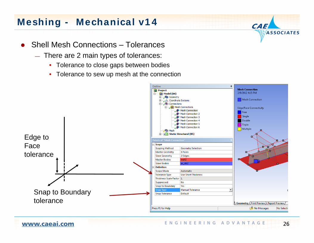
Shell Mesh Connections Tolerances Shell Mesh Connections – Tolerances— There are 2 main types of tolerances:
• Tolerance to close gaps between bodies• Tolerance to sew up mesh at the connectionTolerance to sew up mesh at the connection
Edge toEdge to Face tolerance
Snap to Boundary t l
26www.caeai.com
tolerance

MeshingD t tiDemonstration
CAE Associates Inc. and ANSYS Inc. Proprietary© 2012 CAE Associates Inc. and ANSYS Inc. All rights reserved.

Selective Meshing Demonstration
1 Email Christina Capasso at capasso@caeai com for access to yje1. Email Christina Capasso at [email protected] for access to yjeSelective Meshing Demonstration file.
2. Open Workbench and use File > Restore Archive to open the file “Selective meshing demo wbpz”Selective_meshing_demo.wbpz .
2. Double click on the Model row to open Mechanical.
28www.caeai.com

Selective Meshing Demonstration
4 Begin adding mesh controls Note: the order of definition is not important4. Begin adding mesh controls. Note: the order of definition is not important as the Selective Meshing recording will define the order in which the controls are used.
— Define a global size control of 0 1”— Define a global size control of 0.1 . — Insert a Sweep control on the hook body with a manual source face.
29www.caeai.com

Selective Meshing Demonstration
RMB click on the sweep method and choose “Inflate This Method”— RMB click on the sweep method and choose Inflate This Method .
30www.caeai.com

Selective Meshing Demonstration
Define the Inflation boundary using edges from the source face— Define the Inflation boundary using edges from the source face. — Define the Inflation Options.
Inflation Edges
31www.caeai.com

Selective Meshing Demonstration
Define a Sweep Method on the base body— Define a Sweep Method on the base body. — Duplicate the previous effort to inflate the mesh at the base of the fillet. — Add a Sizing control to the edges at the base of the fillet.
32www.caeai.com

Selective Meshing Demonstration
Add a Sizing control to the fillet body— Add a Sizing control to the fillet body.
33www.caeai.com

Selective Meshing Demonstration
5 RMB click on the Mesh item and select “Start Recording”5. RMB click on the Mesh item and select Start Recording .
34www.caeai.com

Selective Meshing Demonstration
6 RMB click on the Mesh item and select “Start Recording”6. RMB click on the Mesh item and select Start Recording .
35www.caeai.com

Selective Meshing Demonstration
7 Drag the Worksheet tab to the center of the graphics window and7. Drag the Worksheet tab to the center of the graphics window and selection one of the docking locations (left, right, top, bottom).
36www.caeai.com

Selective Meshing Demonstration
8 Individually select each body and RMB click to generate the mesh For8. Individually select each body and RMB click to generate the mesh. For Hex to Tet bodies mesh the sweep method bodies first. Note that the steps are stored in the Worksheet.
37www.caeai.com

Mechanical Update
CAE Associates Inc. and ANSYS Inc. Proprietary© 2012 CAE Associates Inc. and ANSYS Inc. All rights reserved.

Mechanical - Summary Faster Mechanical startup. Cyclic Symmetry for shell bodies. Contact Expanded Named Selection Tools.p
— definition by criteria. — mesh based Named Selections.
FE model exposure.FE model exposure. Post Processing Command blocks. Solver directory access.
External Data improvements External Data improvements. Linear Dynamics. Pipe Element Support for line bodies (Pressure and temperature loads can
be defined as constant, tabular, or functional). Design Assessment. Rigid Body Dynamics.
39www.caeai.com

Cyclic Symmetry for Surface Bodies
Available for both Static and Modal analyses Available for both Static and Modal analyses. Boundary meshes are automatically matched.
40www.caeai.com
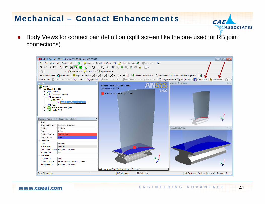
Mechanical – Contact Enhancements
Body Views for contact pair definition (split screen like the one used for RB joint Body Views for contact pair definition (split screen like the one used for RB joint connections).
41www.caeai.com
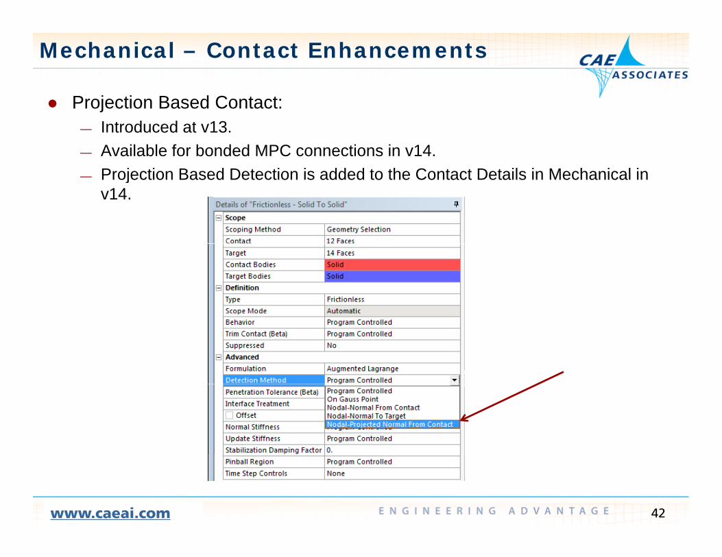
Mechanical – Contact Enhancements
Projection Based Contact: Projection Based Contact: — Introduced at v13. — Available for bonded MPC connections in v14.
Projection Based Detection is added to the Contact Details in Mechanical in— Projection Based Detection is added to the Contact Details in Mechanical in v14.
42www.caeai.com

Mechanical – Contact Enhancements
A Stabilization Damping Factor can be added to contact regions to help A Stabilization Damping Factor can be added to contact regions to help deal with rigid body motion caused by initial gaps.
— Alternative to Adjust to TouchTo be discussed in greater detail during the MAPDL presentation— To be discussed in greater detail during the MAPDL presentation.
Adjust to touch
Stabilization Damping
43www.caeai.com

Mechanical – Contact Enhancements
Program Controlled Defaults at v14: Program Controlled Defaults at v14: — Behavior :
• Asymmetric• SymmetricSymmetric• Auto-asymmetric
— Formulation :• Augmented Lagrangeg g g• Pure Penalty• Normal Lagrange
— Detection Method :• On Gauss point• Nodal-Normal from Contact• Nodal-Normal to Target• Nodal Projected Normal from Contact• Nodal-Projected Normal from Contact
— Update Stiffness :• Never• Each iteration
44www.caeai.com
Each iteration• Each Iteration-Aggressive

Mechanical – Contact Enhancements
Use the Tools > Options menu to override the default “Program Use the Tools > Options menu to override the default Program Controlled” settings for:
— BehaviorFormulation— Formulation
— Update Stiffness
45www.caeai.com

External Data UtilitUtility
CAE Associates Inc. and ANSYS Inc. Proprietary© 2012 CAE Associates Inc. and ANSYS Inc. All rights reserved.

Mechanical – External Data
The External Data Utility was introduced at v13 for mapping pressures The External Data Utility was introduced at v13 for mapping pressures, temperatures and heat transfer coefficients across dissimilar meshes.
New features in v14 include: Mapping point cloud thickness data onto shell elements— Mapping point cloud thickness data onto shell elements.
— Using multiple source files. — Using a “Master” coordinate file to speed up the mapping process.
Validation tools to visually access the data mapping— Validation tools to visually access the data mapping. — Activation/Deactivation of imported loads.
47www.caeai.com

Mechanical – External Data
Multiple source files using the File Identifier in Mechanical Multiple source files, using the File Identifier in Mechanical. A “Master File” can be defined to reuse X,Y,Z coordinates for increased
mapping speed.
48www.caeai.com
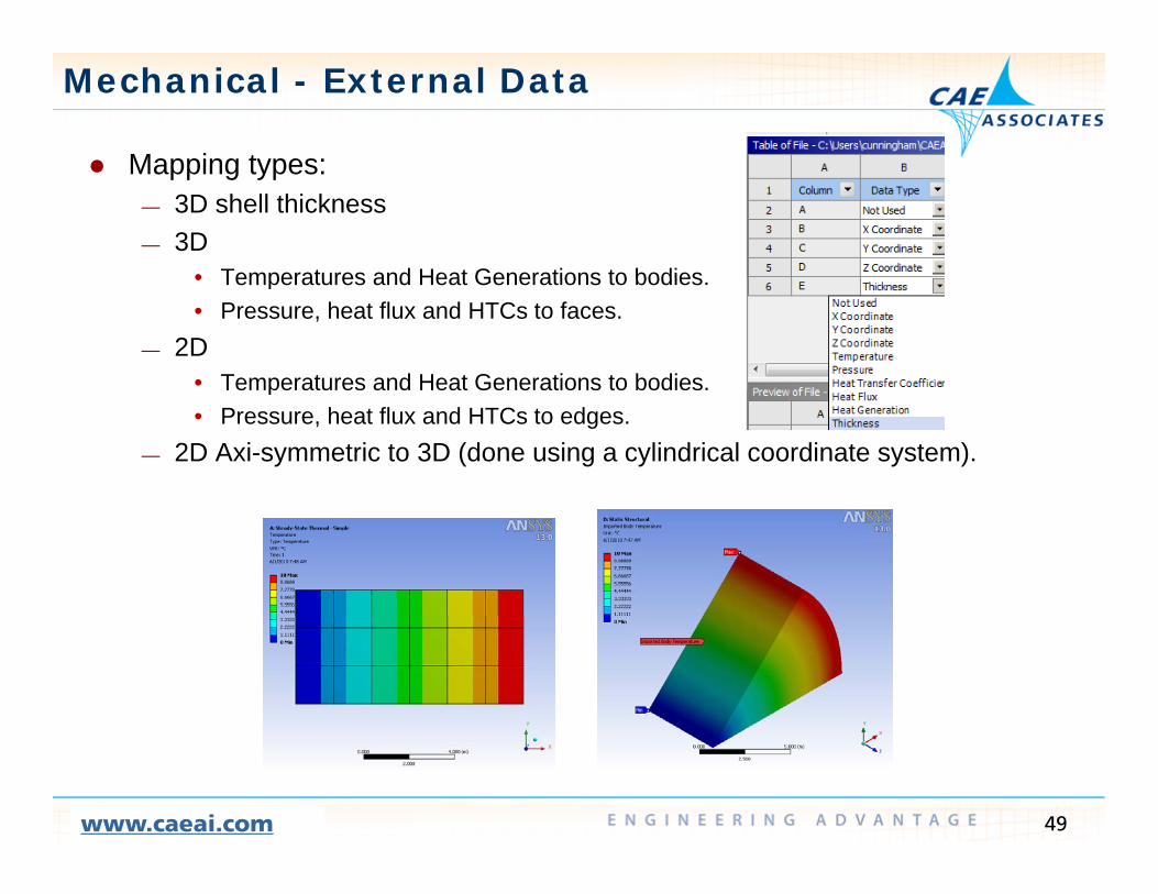
Mechanical - External Data
Mapping types: Mapping types: — 3D shell thickness— 3D
• Temperatures and Heat Generations to bodies• Temperatures and Heat Generations to bodies.• Pressure, heat flux and HTCs to faces.
— 2D• Temperatures and Heat Generations to bodies.p• Pressure, heat flux and HTCs to edges.
— 2D Axi-symmetric to 3D (done using a cylindrical coordinate system).
49www.caeai.com
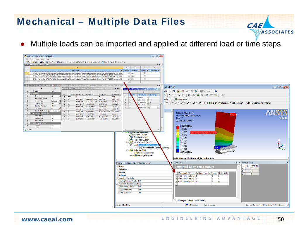
Mechanical – Multiple Data Files
Multiple loads can be imported and applied at different load or time steps Multiple loads can be imported and applied at different load or time steps.
50www.caeai.com
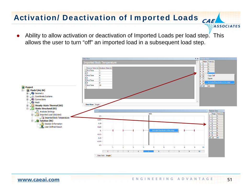
Activation/Deactivation of Imported Loads
Ability to allow activation or deactivation of Imported Loads per load step This Ability to allow activation or deactivation of Imported Loads per load step. This allows the user to turn “off” an imported load in a subsequent load step.
51www.caeai.com

Mechanical - External Data
The Validation Tool has been added enabling evaluation of the data The Validation Tool has been added enabling evaluation of the data mapping:
— Reverse mapping (map from source to target and back to source). Distance based averaging comparison— Distance based averaging comparison
— Source Value plots source data onto the mapped data directly
52www.caeai.com

External DataD t tiDemonstration
CAE Associates Inc. and ANSYS Inc. Proprietary© 2012 CAE Associates Inc. and ANSYS Inc. All rights reserved.
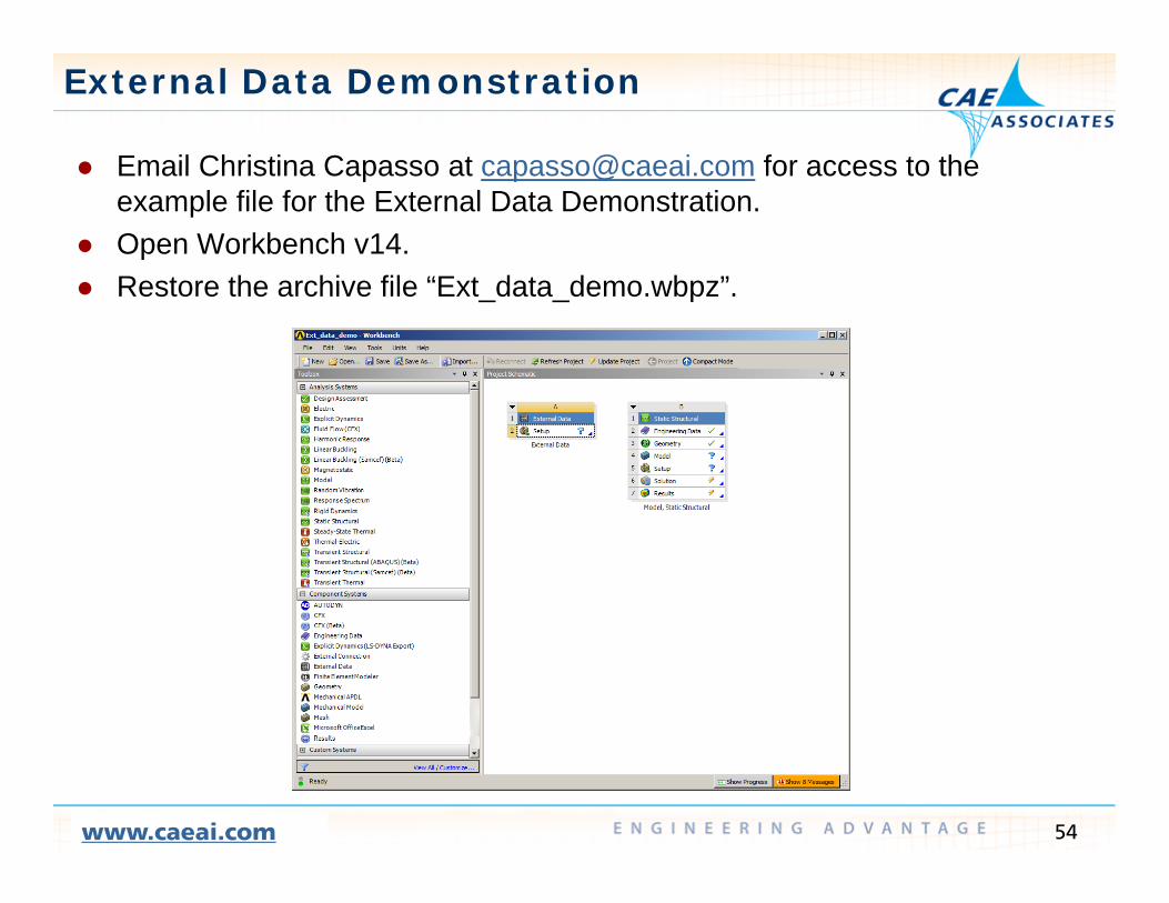
External Data Demonstration
Email Christina Capasso at capasso@caeai com for access to the Email Christina Capasso at [email protected] for access to the example file for the External Data Demonstration.
Open Workbench v14. Restore the archi e file “E t data demo bp ” Restore the archive file “Ext_data_demo.wbpz”.
54www.caeai.com

External Data Demonstration
1 Double click on the Setup row of the External Data utility1. Double click on the Setup row of the External Data utility. 2. Select File1 (bladethick.csv).3. Set the Format Type to Delimited. 4 Set the Delimiter Type to Comma4. Set the Delimiter Type to Comma. 5. Confirm that the length unit is set to inches. 2.
1. 5.
3.
4.
55www.caeai.com

External Data Demonstration
6 Set the Data Type for columns B C and D to X Y and Z Coordinate6. Set the Data Type for columns B, C, and D to X, Y, and Z Coordinate respectively.
7. Set the Data Type of column E to thickness. 8. Check the column headers in the Preview window. 6. 78. Check the column headers in the Preview window. 7.
8.
56www.caeai.com

External Data Demonstration
9 Return to the Project Page and update the External Data object9. Return to the Project Page and update the External Data object. 10. Drag and drop the External Data object onto the model row of the Static Structural
analysis system and refresh the Model.
57www.caeai.com

External Data Demonstration
11 Double click on the Model row to open Mechanical11. Double click on the Model row to open Mechanical. 12. Scope the Imported Thickness to the blade surface body. 13. RMB to import the thickness values onto the shell body.
58www.caeai.com

External Data Demonstration
14 RMB click on “Imported14.
14. RMB click on Imported Thickness” and insert a validation object.
15. Set the validation Type to “Source Value”.
16. Set “Display on Parent to “On”. 17. RMB click on the Validation to
17.
“Analyze”. 18. Click on the Imported Thickness
to view the validation of the source versys mapped data
15.
16.source versys mapped data.
18.
59www.caeai.com

External Data Demonstration19. Return to the External Data Utility and Select File2.20 Repeat the setup of the X Y and Z Coordinate data columns for File2 and set the Data20. Repeat the setup of the X, Y, and Z Coordinate data columns for File2 and set the Data
Type for column E to Temperature. 21. On the project page drag and drop onto the Setup and refresh. 22. Import the temperature load and analyze Reverse Mapping of Relative Difference
Output on the blade body. 23. Narrow the Maximum relative to the blade area (~.65% max).
19.
20. 21.
22.
60www.caeai.com
23.

Named Selections
CAE Associates Inc. and ANSYS Inc. Proprietary© 2012 CAE Associates Inc. and ANSYS Inc. All rights reserved.

Mechanical - Named Selections
Nodal based Named Selections (called “Mesh Node” selections) can be Nodal based Named Selections (called Mesh Node selections) can be now created using the Worksheet.
62www.caeai.com

Mechanical - Named Selections
Mesh Node selections can be defined by: Mesh Node selections can be defined by:— Attachment to solid model Named Selections. — Location with respect to a specified coordinate system.
Type (corner or mid side node)— Type (corner or mid-side node). — Node ID (node number).— Node ID range.
Smallest or largest Node ID in the selected group— Smallest or largest Node ID in the selected group.
63www.caeai.com

Mechanical - Named Selections
Multiple operations can be used to re-select Mesh Node groups Multiple operations can be used to re-select Mesh Node groups. Example: Select nodes attached to a surface. Reselect the corner nodes.
64www.caeai.com

Mechanical – Mesh Node Selections
Nodes can be selected directly from the Mesh Nodes can be selected directly from the Mesh item.
1. Select Mesh in the Outline window2 Toggle Select Type from Geometry to Mesh2. Toggle Select Type from Geometry to Mesh.
2.
1.
There are several selection modes: — Single Select— Box Select (surface nodes)— Box Volume Select (surface and internal)— Lasso Select (surface nodes)— Lasso Volume Select (surface and internal)
65www.caeai.com
( )

Mechanical - Selection Information
Use View > Windows > Selection Information to view the details of a Use View > Windows > Selection Information to view the details of a nodal selection.
66www.caeai.com

Mechanical - Using Selected Nodes
You can create Mesh Node Named Selections directly from a selected set You can create Mesh Node Named Selections directly from a selected set of nodes using the Named Selection tool bar (View > Toolbars > Named Selections).
67www.caeai.com

Mechanical - Direct FE Loading
You can apply loads directly to Mesh Node selections at v14 using the You can apply loads directly to Mesh Node selections at v14 using the “Direct FE” pull down menu. Note: Direct FE loads are defined by scoping to existing Mesh Node Named Selections onlyNamed Selections only.
68www.caeai.com

Mechanical - Direct FE Loading
Nodal Orientation is used to align a Mesh Node selection to a specified Nodal Orientation is used to align a Mesh Node selection to a specified coordinate system.
It allows you to modify specific nodes rather than all nodes attached to a geometry selectiongeometry selection.
69www.caeai.com

Mechanical - Direct FE Loading
Nodal Force give the users the option to distribute the total force over the Nodal Force give the users the option to distribute the total force over the selected nodes or apply to the total force to each node.
70www.caeai.com

Mechanical – Node Selections
You can export node numbers and nodal coordinates for Node Selections You can export node numbers and nodal coordinates for Node Selections with a RMB click. Note: You must set Tools > Options > Export to include the nodal coordinatescoordinates.
71www.caeai.com

Mechanical – Node Selections
Including the nodal coordinates in the data export is also useful for Including the nodal coordinates in the data export is also useful for exporting result data.
72www.caeai.com

Mechanical - FE Model Exposure
Direct FE boundary conditions and connections can be visualized by Direct FE boundary conditions and connections can be visualized by picking on the analysis and Solution Information folders.
Displayed items include weak springs, remote loads, and MPC bonded contact constraint equationscontact constraint equations.
73www.caeai.com

Postprocessing
CAE Associates Inc. and ANSYS Inc. Proprietary© 2012 CAE Associates Inc. and ANSYS Inc. All rights reserved.

Postprocessing Command Blocks
At v14 postprocessing command blocks can be added and evaluated after At v14 postprocessing command blocks can be added and evaluated after the solution is complete (no complete re-solve is required).
When a post solution command block is evaluated Mechanical will write a batch solution file and submit it to the ANSYS solverbatch solution file and submit it to the ANSYS solver.
— The default name for batch input file is “post.dat” — A corresponding output file “post.out” is also generated in the folder.
Use the RMB on the Solution item to open the solution folder to view the Use the RMB on the Solution item to open the solution folder to view the files.
75www.caeai.com

Tips for Postprocessing
1 Not all quantities are written to the result file by default1. Not all quantities are written to the result file by default. — If you plan to postprocess force or contact data you will need to set the
output controls prior to the solution (Analysis Settings > Output Controls). — This can also be set as the default using the Tools > Options > MechanicalThis can also be set as the default using the Tools > Options > Mechanical
> Analysis Settings and Solution.
76www.caeai.com
Tips for Postprocessing Command Blocks
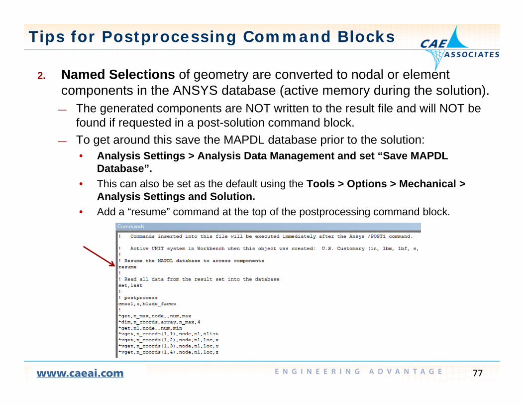
2 Named Selections of geometry are converted to nodal or element2. Named Selections of geometry are converted to nodal or element components in the ANSYS database (active memory during the solution).
— The generated components are NOT written to the result file and will NOT be found if requested in a post-solution command block.found if requested in a post solution command block.
— To get around this save the MAPDL database prior to the solution: • Analysis Settings > Analysis Data Management and set “Save MAPDL
Database”.• This can also be set as the default using the Tools > Options > Mechanical >
Analysis Settings and Solution. • Add a “resume” command at the top of the postprocessing command block.
77www.caeai.com

Tips for Postprocessing Command Blocks
3 Use the SET command to read all quantities from the results file3. Use the SET command to read all quantities from the results file. — The MAPDL database is saved after the solution but not all quantities are
stored.
78www.caeai.com

Tips for Postprocessing Command Blocks
4 When evaluating a postprocessing command block on a model with a4. When evaluating a postprocessing command block on a model with a completed solution you may need to redirect ANSYS to the appropriate result file type.
— The solver uses the default /POST1 > FILE setting which looks for a file with— The solver uses the default /POST1 > FILE setting which looks for a file with an .RST extension.
— If the analysis is of another type you will need to use the FILE command in the command block.
Example: Postprocessing a thermal result requires a FILE,,RTH command
79www.caeai.com

Mechanical – Solution Directory
The Solution directory can be easily accessed at v14 via a RMB click on The Solution directory can be easily accessed at v14 via a RMB click on the Solution folder.
80www.caeai.com

Design A tAssessment
CAE Associates Inc. and ANSYS Inc. Proprietary© 2012 CAE Associates Inc. and ANSYS Inc. All rights reserved.
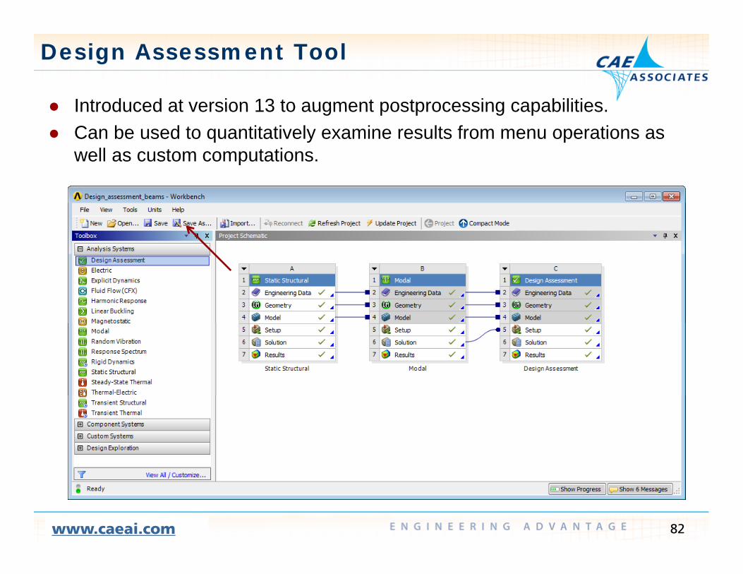
Design Assessment Tool
Introduced at version 13 to augment postprocessing capabilities Introduced at version 13 to augment postprocessing capabilities. Can be used to quantitatively examine results from menu operations as
well as custom computations.
82www.caeai.com

Design Assessment Tool
Examples : can be used like the Solution Combination tool for linear Examples : can be used like the Solution Combination tool for linear superposition of different environments.
83www.caeai.com

Design Assessment Tool
E l b d t filt i f lt it Examples: can be used to overcome filtering of result items. Beam stresses from a modal analysis are not available in the standard postprocessing tools. Design Assessment can be used to get around this.
84www.caeai.com

Design Assessment–Custom Computations
Example: Calculate Creep Life using the Larson Miller parameter: Example: Calculate Creep Life using the Larson Miller parameter:
Input: Larson-Miller Coefficients from test data.
0*1*2*3*4*5*6 23456 CCCCCCCLMP
Output: Larson-Miller parameter and Creep Life based on calculated stress.
C
TLMP
LifeCreep 10
85www.caeai.com

Design Assessment–Custom Computations
A Design Assessment Attribute Group is used to define the Larson Miller A Design Assessment Attribute Group is used to define the Larson Miller parameter equation and coefficients:
0*1*2*3*4*5*6 23456 CCCCCCCLMP 0*1*2*3*4*5*6 23456 CCCCCCCLMP
86www.caeai.com

Design Assessment – User Attribute File
Result quantities display the LMP and Creep Life based on stress results Result quantities display the LMP and Creep Life based on stress results and inputs.
C
TLMP
TLifeCreep 10
87www.caeai.com

Design Assessment–Documented Examples
Design Assessment Customization: Design Assessment Customization:— // Mechanical Application User's Guide // Features // Design Assessment :: 0
88www.caeai.com

Design Assessment V14 CustomizationV14 Customization
Example
CAE Associates Inc. and ANSYS Inc. Proprietary© 2012 CAE Associates Inc. and ANSYS Inc. All rights reserved.

Custom Computations using Design Assessment
Email Christina Capasso at capasso@caeai com for access to the v14 Email Christina Capasso at [email protected] for access to the v14Design Assessment example file.
Extract the contents of the file “DA_v14_example.zip” using WinZip®.Open Workbench 14 and import the file “DA 14 e ample mechdat” Open Workbench v14 and import the file “DA_v14_example.mechdat”.
Save the project.
90www.caeai.com

Custom Computations using Design Assessment
Drag and drop Design Assessment onto the “Static Structural” Solution Drag and drop Design Assessment onto the Static Structural Solution Cell
91www.caeai.com

Design Assessment – User Attribute File
Setup a “User Defined” Assessment Type and browse to the file “LMP xml” Setup a User Defined Assessment Type and browse to the file LMP.xml extracted from the zip file.
RMB Click
92www.caeai.com
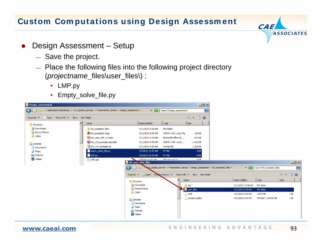
Custom Computations using Design Assessment
Design Assessment Setup Design Assessment – Setup— Save the project.— Place the following files into the following project directory
(projectname files\user files\) :(projectname_files\user_files\) :• LMP.py• Empty_solve_file.py
93www.caeai.com
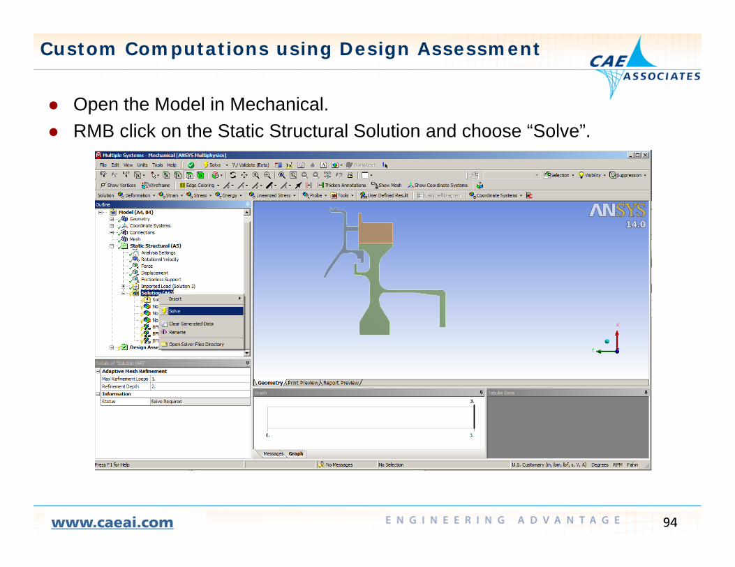
Custom Computations using Design Assessment
Open the Model in Mechanical Open the Model in Mechanical. RMB click on the Static Structural Solution and choose “Solve”.
94www.caeai.com

Custom Computations using Design Assessment
Open “Design Assessment” Open Design Assessment Under “Solution Selection” the Environment Name to “Static Structural”.
— Any “Time” and “Step” numbers can be selected. These values are not used!
95www.caeai.com

Custom Computations using Design Assessment
Input the coefficients of the curve fit to your test data Input the coefficients of the curve fit to your test data. — RMB click on Design Assessment > Insert > Attribute Group— Be sure the units in Mechanical match the test data (mm, kg, N).
0*1*2*3*4*5*6 23456 CCCCCCCLMP
96www.caeai.com

Design Assessment – User Attribute File
Calculate the Larson Miller Parameter (LMP) based on the stress results Calculate the Larson Miller Parameter (LMP) based on the stress results and the test data.
— RMB click on Solution > Insert > DA Result• Select Stress Component to use when calculating the LMPSelect Stress Component to use when calculating the LMP• The “Set Number” corresponds to the result set from the structural analysis
environment (this set is used instead of the “Solution Selection” time).
97www.caeai.com

Design Assessment – User Attribute File
Calculate Larson Miller Life based on stress results and curve fit Calculate Larson Miller Life based on stress results and curve fit.— RMB click on Solution > Insert > DA Result
• Select Stress Component to use when calculating the LMP• LMP C: Larson Miller ConstantLMP C: Larson Miller Constant• Temperature: Constant uniform temperature to be used in the life calculation.• Maximum Life: Contour cutoff value (or use zero for no limit).• The “Set Number” corresponds to the result set from the structural analysis
environment (this set is used instead of the “Solution Selection” time).
98www.caeai.com
C
TLMP
ConstLifeCreep 10

Linear Dynamics
CAE Associates Inc. and ANSYS Inc. Proprietary© 2012 CAE Associates Inc. and ANSYS Inc. All rights reserved.
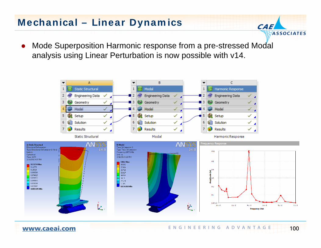
Mechanical – Linear Dynamics
Mode Superposition Harmonic response from a pre-stressed Modal Mode Superposition Harmonic response from a pre-stressed Modal analysis using Linear Perturbation is now possible with v14.
100www.caeai.com

Mechanical – Linear Dynamics
Mode Superposition Transient Analysis is now available at v14 Mode Superposition Transient Analysis is now available at v14. Note : The modal analysis cannot include pre-stress.
101www.caeai.com

Mechanical – Linear Dynamics
Joint connections are available in v14 for Modal Harmonic Spectrum and Joint connections are available in v14 for Modal, Harmonic, Spectrum and Random Vibration analysis.
102www.caeai.com

Mechanical – Linear Dynamics
Reaction Force and Moment probes are now available for Modal and Reaction Force and Moment probes are now available for Modal and Harmonic analyses. Note: Reaction Forces must be turned on in the Analysis settings prior to solvingsolving.
103www.caeai.com
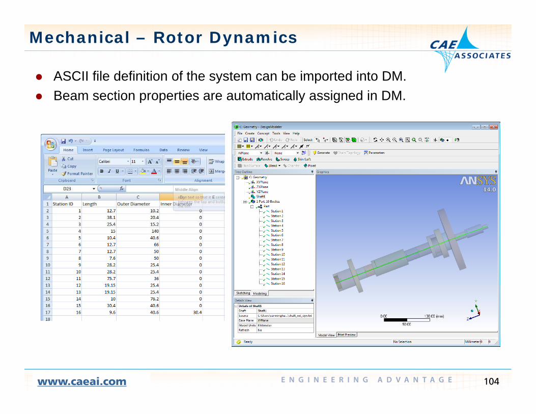
Mechanical – Rotor Dynamics
ASCII file definition of the system can be imported into DM ASCII file definition of the system can be imported into DM. Beam section properties are automatically assigned in DM.
104www.caeai.com

Mechanical – Rotor Dynamics
The Analysis Settings are used to define the Damped Modal solver turn The Analysis Settings are used to define the Damped Modal solver, turn on Coriolis Effects, generate a Campbell, and define the number of sppedpoints.
105www.caeai.com

Import/Export of Bearing Characteristics
ANSYS supplies a macro called IMPORTBEARING1 that reads bearing ANSYS supplies a macro called IMPORTBEARING1 that reads bearing characteristics from an external file.
ET,_sid,combi214,,2,1 ! XZ plane, unsymIMPORTBEARING1,'..\..\bearing',1
r,_sid, %K11_1%, %K22_1%,%K12_1%,%K21_1%,%C11_1%,%C22_1%,rmore, %C12_1%, %C21_1%
106www.caeai.com

Mechanical – Rotor Dynamics
Campbell Diagrams are generated in the Solution folder Campbell Diagrams are generated in the Solution folder.
107www.caeai.com

Rigid Body Dynamics
Principal Development Areas in v14 Principal Development Areas in v14. — Extend 3D Contact
• Focus on performance and robustnessExtend Joint Behavior using command blocks and Python programming— Extend Joint Behavior using command blocks and Python programming.
— Extended Post-Processing — Simplorer-RBD Co-simulation
108www.caeai.com

Rigid Body Dynamics
Continued development of general (nonlinear) contact for Rigid Body Continued development of general (nonlinear) contact for Rigid Body Dynamics.
109www.caeai.com

Rigid Body Dynamics
RBD Command snippets using the Python language allow representation RBD Command snippets using the Python language allow representation of complex relationships between joints, help create new load conditions and provide results export.
These are documented in: These are documented in: // Mechanical Application User's Guide // Approach // Analysis Types // Transient Structural and Rigid Dynamics Analyses // Command Reference for Rigid Dynamics Systems
110www.caeai.com
Dynamics Systems

System Level Analysis with Simplorer
Couple control system design with a rigid dynamic system using Couple control system design with a rigid dynamic system using Simplorer’s large library of hydraulic, electric, electronic components.
Include realistic mechanical models as part of a system level simulation.
111www.caeai.com
Explicit Dynamics
CAE Associates Inc. and ANSYS Inc. Proprietary© 2012 CAE Associates Inc. and ANSYS Inc. All rights reserved.

Explicit Dynamics
New Tetrahedral Element New Tetrahedral Element— Nodal Based Strain (NBS) formulation
• Overcomes both volume and shear locking• Particularly valuable in low velocity applications involving complex geometryParticularly valuable in low velocity applications involving complex geometry
(consumer drops like mobile phones, nuclear equipment drops)— Beam bending example
Case Average End Deflection
ANP Tet (default) -0.178NBS Tet -0.146MAPDL -0.147
113www.caeai.com

Explicit Dynamics
2D Plain Strain and Axisymmetric solid analyses are now supported for 2D Plain Strain and Axisymmetric solid analyses are now supported for Explicit Dynamics
2D forming example:— 2D forming example:
114www.caeai.com

Explicit Dynamics
Can now obtain results at specific Can now obtain results at specific points at a high output frequency.
Can also obtain reaction forces Can also obtain reaction forces
115www.caeai.com

Explicit Dynamics
Discrete thickness shells Import point cloud Discrete thickness shells – Import point cloud thickness using External Data Utility.
Example: Import from ANSYS Polyflow
116www.caeai.com

Explicit Dynamics
Explicit Dynamics available with Design Assessment Explicit Dynamics available with Design Assessment Design Assessment was introduced in Workbench to enable customized
post-processing of Mechanical systemsProgrammable/scriptable means to access results— Programmable/scriptable means to access results
Explicit Dynamics can now be an upstream system for Design Assessment
117www.caeai.com

Explicit Dynamics
Explicit STR can be used with Design Assessment: Explicit STR can be used with Design Assessment: — Allows users to generate custom scripts to generate user-defined results and
plot them.— Scripts are written in pythonScripts are written in python.
Example with Explicit Dynamics— Calculation of number of fragments, volume of fragments, and mass of
fragments based on the solved damage in each elementfragments based on the solved damage in each element.
Fragment Volume
118www.caeai.com

Explicit Dynamics
Enhanced Composite Shell Modelinga ced Co pos te S e ode g— Layered shells now supported— Composite failure material properties defined in Engineering Data now
supportedpp— Can interface with ACP to define composite properties
ACP Workflow with Mechanical / Explicit Dynamics
Parameter Support
Allows for inclusion as part of Design Exploration
119www.caeai.com
of Design Exploration

Parametric M d liModeling
CAE Associates Inc. and ANSYS Inc. Proprietary© 2012 CAE Associates Inc. and ANSYS Inc. All rights reserved.

Parametric Modeling
The ANSYS Workbench environment is designed to take full advantage of The ANSYS Workbench environment is designed to take full advantage of feature based parametric CAD geometry files.
The Parameter Set tool is the link between the CAD geometry and the Mechanical analysis toolMechanical analysis tool.
121www.caeai.com

Parametric Modeling
The Parameter Set lets you manage all current parameter values as well The Parameter Set lets you manage all current parameter values as well as define a table of possible variations of geometry, material, and loading values.
Output parameters (result quantities) are also stored for each design point Output parameters (result quantities) are also stored for each design point.
Set up a table ofModify the parameter values of the current design
Set up a table of design variations
Define associations
122www.caeai.com
Define associations between parameters

Parametric Modeling
Populate the Table of Design Points by entering or pasting in values for Populate the Table of Design Points by entering or pasting in values for the input parameters.
Evaluate the design points and plot the response by adding Parameter Charts to the Outline in the upper leftCharts to the Outline in the upper left.
123www.caeai.com

Parametric Modeling
Additional capabilities are available using the Workbench add-on tool Additional capabilities are available using the Workbench add-on tool Design Exploration.
With Design Exploration users can indentify optimum design parameters using the Goal Driven Optimization and Six Sigma analysis methodsusing the Goal Driven Optimization and Six Sigma analysis methods.
124www.caeai.com

Goal Driven Optimization
With Goal Driven Optimization you can import your existing design points With Goal Driven Optimization you can import your existing design points from the Parameter Manager or use one of several DOE design point generation methods:
125www.caeai.com

Goal Driven Optimization
Response surfaces and sensitivity plots can be used to evaluate the Response surfaces and sensitivity plots can be used to evaluate the input/output relationship for each design point.
126www.caeai.com
Goal Driven Optimization
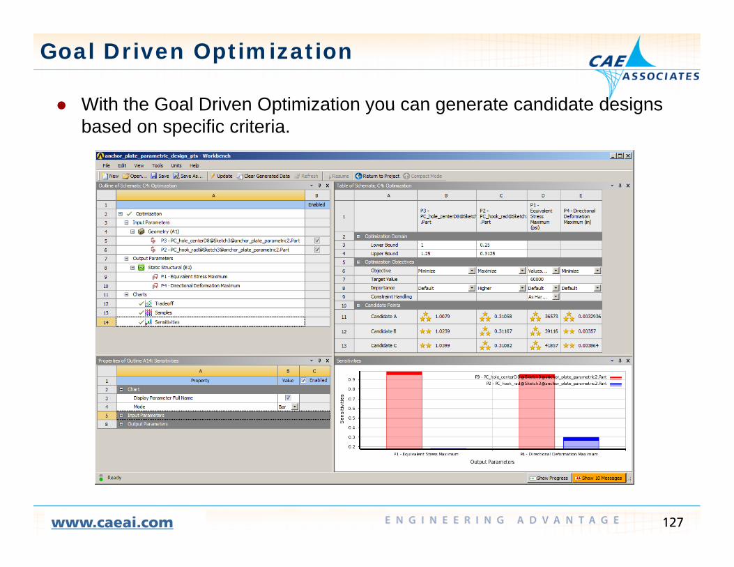
With the Goal Driven Optimization you can generate candidate designs With the Goal Driven Optimization you can generate candidate designs based on specific criteria.
127www.caeai.com
Six Sigma Analysis
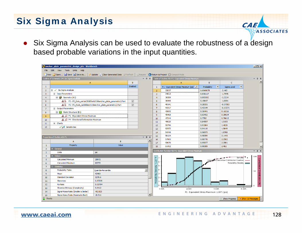
Six Sigma Analysis can be used to evaluate the robustness of a design Six Sigma Analysis can be used to evaluate the robustness of a design based probable variations in the input quantities.
128www.caeai.com

Using the Remote Solve Manager with Solve Manager with Parametric Design
StudiesStudies
CAE Associates Inc. and ANSYS Inc. Proprietary© 2012 CAE Associates Inc. and ANSYS Inc. All rights reserved.

Using RSM in WB
The Remote Solve Manager is an The Remote Solve Manager is an ANSYS utility with which you can identify other computers on your network that can be used to generatenetwork that can be used to generate your ANSYS solution.
You can identify single “remote” solver machines or a cluster of machines thatmachines or a cluster of machines that can be used for simultaneous processing of individual design points.
When solving interactively, Remote Clusters will be visible in the Solve pull down menu. do e u
130www.caeai.com

Remote Solve Manager v14 Updates
When using a single machine all When using a single machine all design point solutions are generated in series.
The Remote Solve Manager can be used to generate design point solutions simultaneously using asolutions simultaneously using a cluster of machines.
Expanded RSM Solver Support at v14 Expanded RSM Solver Support at v14— Full support for Mechanical and
Mechanical APDL— More complete support for Fluent andMore complete support for Fluent and
CFX— Supports Serial, Local Parallel, and
Distributed Parallel processing
131www.caeai.com

Submitting Design Points to RSM
Consider a Static Structural analysis that has parametric geometry Consider a Static Structural analysis that has parametric geometry, material and/or loading that you want to evaluate.
To use an RSM cluster to generate each of the design point solutions select the Solution row of the Analysis System and set the “Update Option”select the Solution row of the Analysis System and set the Update Option to “Submit to Remote Solve Manager”.
132www.caeai.com

Submitting Design Points to RSM
If your CAD program is not installed on the Remote Solve machines you If your CAD program is not installed on the Remote Solve machines you will need to generate geometry updates locally.
Set the Update Option in the Properties of the Parameter Set to “Run in ForegroundForeground.
With this configuration the design point files are generated locally in series while the solution files are generated in parallel using the solve cluster.
133www.caeai.com