antenna theory wave propagation - prepare...
TRANSCRIPT

ANTENNA THEORY
WAVE PROPAGATION
&
HF ANTENNAS

FREQUENCY SPECTRUM INFORMATION
Frequency range American designatorbelow 300 Hz…………………..ELF (extremely Low Frequency)300-3000 Hz…………………..ILF (Intermediate Low Frequency)3 - 300 Khz…………………VLF (Very Low Frequency)30-300 Khz…………………LF (Low Frequency)300-3000 Khz…………………MF (Medium Frequency)3 - 30 Mhz………………...HF (High Frequency)30-300 Mhz………………...VHF (Very High Frequency)300-3000 Mhz………………...UHF (Ultra High Frequency)3 - 30 Ghz…………………SHF (Super High Frequency)30-300 Ghz…………………EHF (Extremely High Frequency)
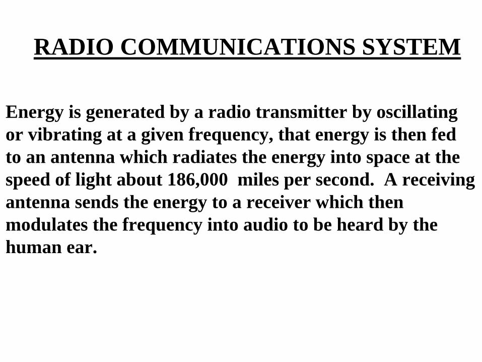
RADIO COMMUNICATIONS SYSTEM
Energy is generated by a radio transmitter by oscillating or vibrating at a given frequency, that energy is then fedto an antenna which radiates the energy into space at the speed of light about 186,000 miles per second. A receiving antenna sends the energy to a receiver which then modulates the frequency into audio to be heard by thehuman ear.

TRANSMITTING ANTENNA
Converts output energy from the radio transmitterinto an electromagnetic field which the receivingantenna converts back to energy acceptable by thereceiver. (A vertical whip antenna radiates orpropagates in a 360 degree radius.
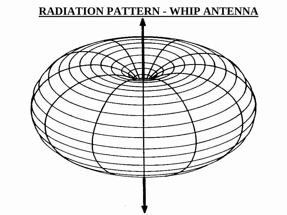
RADIATION PATTERN - WHIP ANTENNA
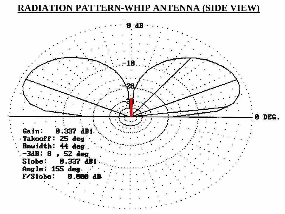
RADIATION PATTERN-WHIP ANTENNA (SIDE VIEW)
RADIO WAVE
Has 3 characteristics and they are: Speed which is the speed of light. Frequency which is the number of cycles completed by a radio wave in one second. Wavelength which is the distance from one point on a radio wave to the same point on the next radio wave.
TYPES OF RADIO WAVES
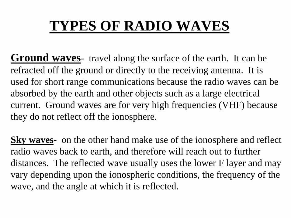
Ground waves- travel along the surface of the earth. It can berefracted off the ground or directly to the receiving antenna. It isused for short range communications because the radio waves can be absorbed by the earth and other objects such as a large electricalcurrent. Ground waves are for very high frequencies (VHF) becausethey do not reflect off the ionosphere.
Sky waves- on the other hand make use of the ionosphere and reflectradio waves back to earth, and therefore will reach out to furtherdistances. The reflected wave usually uses the lower F layer and mayvary depending upon the ionospheric conditions, the frequency of thewave, and the angle at which it is reflected.

GROUND WAVE
SKY WAVE
IONOSPHERE
XMTR RCVR
SKIP ZONE / SKIP DISTANCE
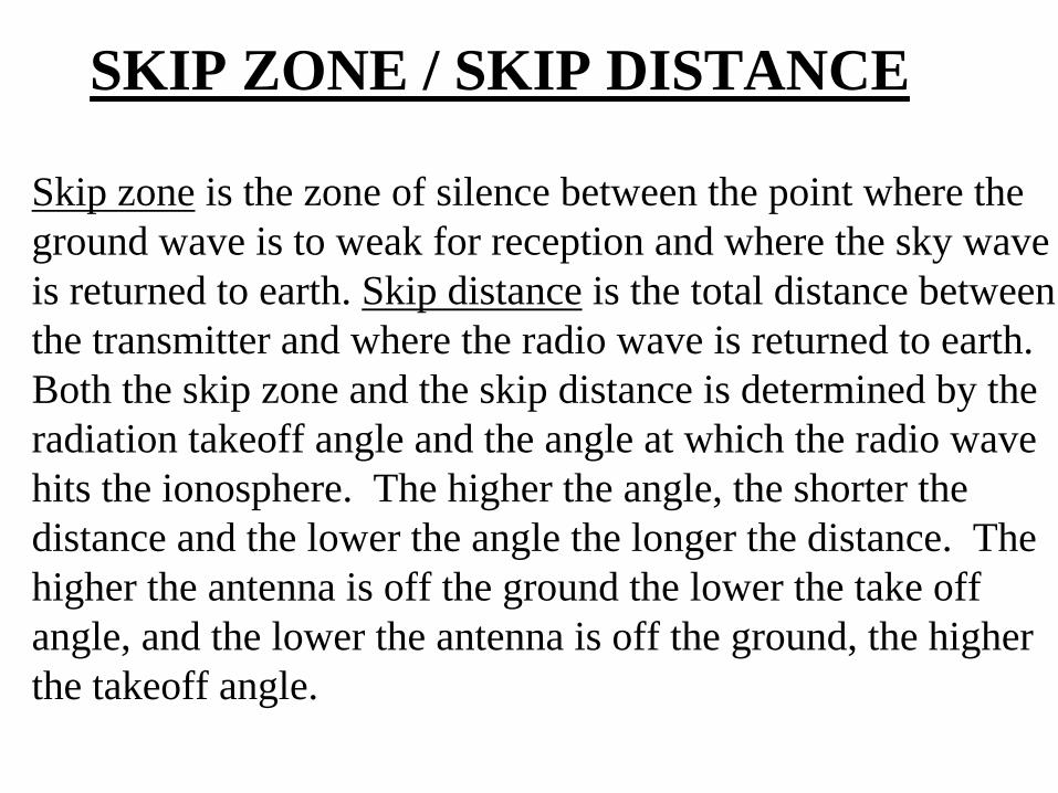
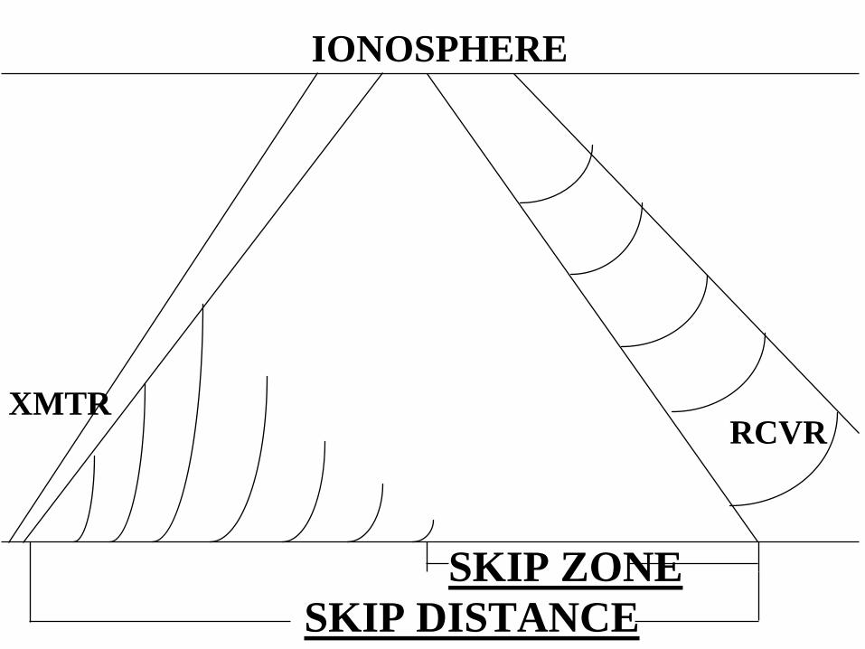
Skip zone is the zone of silence between the point where theground wave is to weak for reception and where the sky waveis returned to earth. Skip distance is the total distance betweenthe transmitter and where the radio wave is returned to earth.Both the skip zone and the skip distance is determined by theradiation takeoff angle and the angle at which the radio wavehits the ionosphere. The higher the angle, the shorter the distance and the lower the angle the longer the distance. Thehigher the antenna is off the ground the lower the take off angle, and the lower the antenna is off the ground, the higherthe takeoff angle.
SKIP ZONESKIP DISTANCE
IONOSPHERE
XMTRRCVR
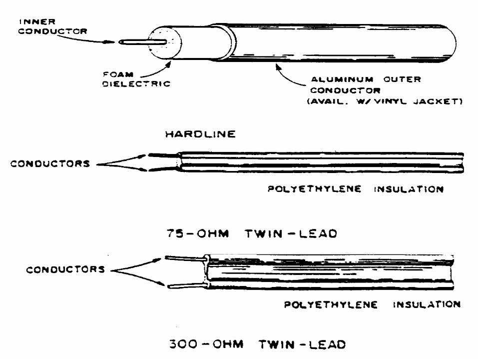
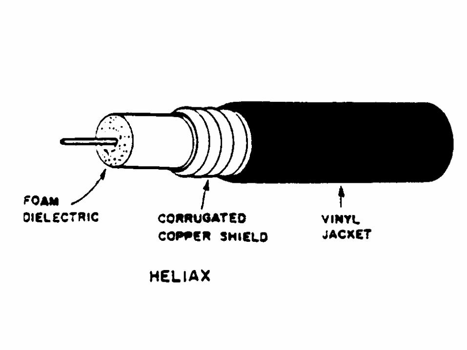
TRANSMISSION LINESThe connecting link between the transmitter and the antenna. There are several types, such as Coaxial cable, single wire, insulated 2 wire, ladder line, and twisted pair. Each transmission line has it’s own characteristic impedence(resistance), and is either balanced or unbalanced. Unbalanced is when one part of the wire is at ground potential, such as coaxial cable. Feed Point is the point at which the transmission is connected to the antenna, usually with a Balun (balanced to unbalanced transformer), or an insulator of some sort.
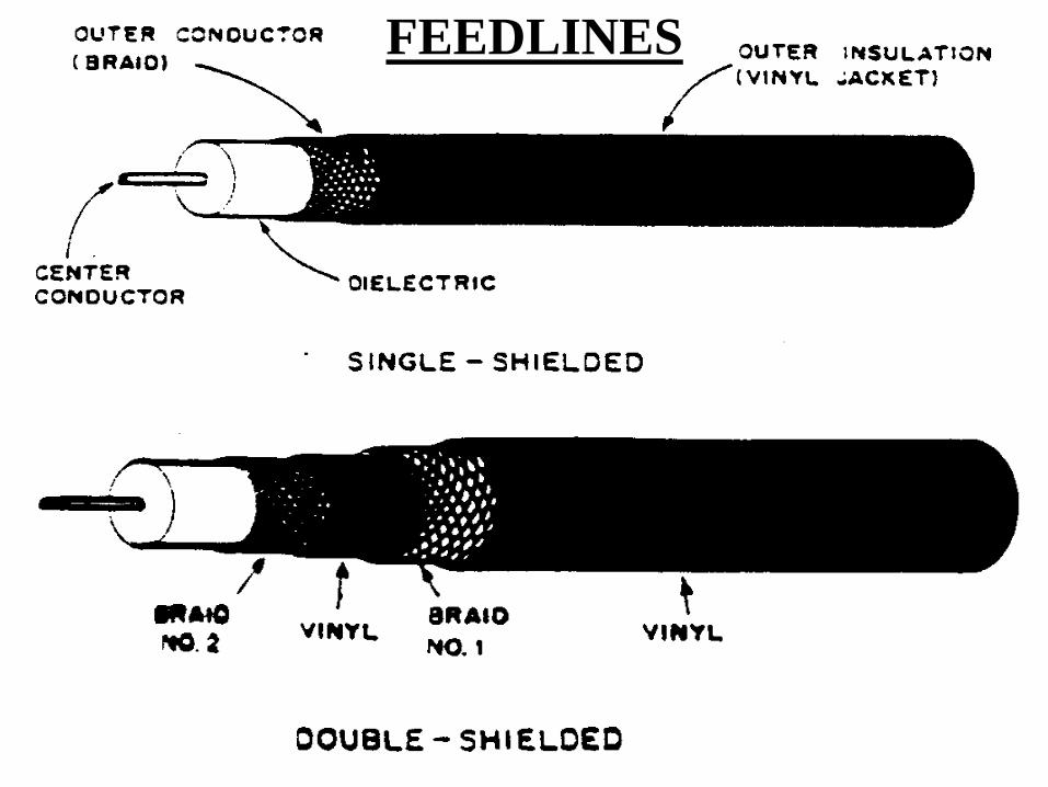
FEEDLINES
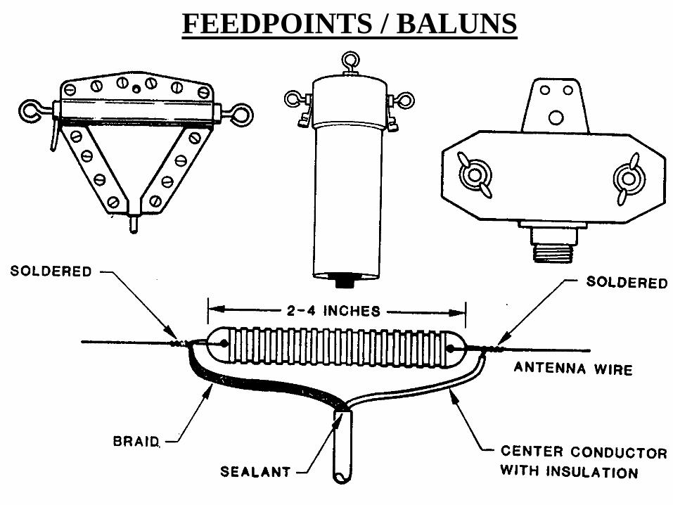
FEEDPOINTS / BALUNS
CONDUCTIVITY
Acts as a mirror for radiated energy and reflects or absorbsradio waves depending upon the type of materials that arecontained in the ground. The best conductor is lots of moisture, such as oceans which contain salt. Dry, Rocky, and Mountainous areas are poor conductors because theirlack of moisture. Jungle areas are also poor mainly becausethe large amounts of vegetation which can absorb or refractthe radio waves.


GROUND CONDUCTIVITY FOR U.S.
COUNTERPOISE
This is a false ground to help provide conductivity in theevent the real ground is a poor conductor. If a counterpoiseis used, it should be the same length as the operating antennaor larger. It can also be used to make an antenna unidirectionalby reflecting the radio wave in the desired direction. For example (Slant, Inverted L, and longwire)
RESONANT
When the physical length of an antenna matches the electrical length or frequency wavelength. This will makethe antenna more efficient for both receiving and transmitting (theory of reciprocity) When an antenna is not resonant it will have a high Standing Wave Ratio, which means the capacitive reactance is not equal or opposite the inductive reactance. Which in simple terms means that the antenna is either too long or too short.
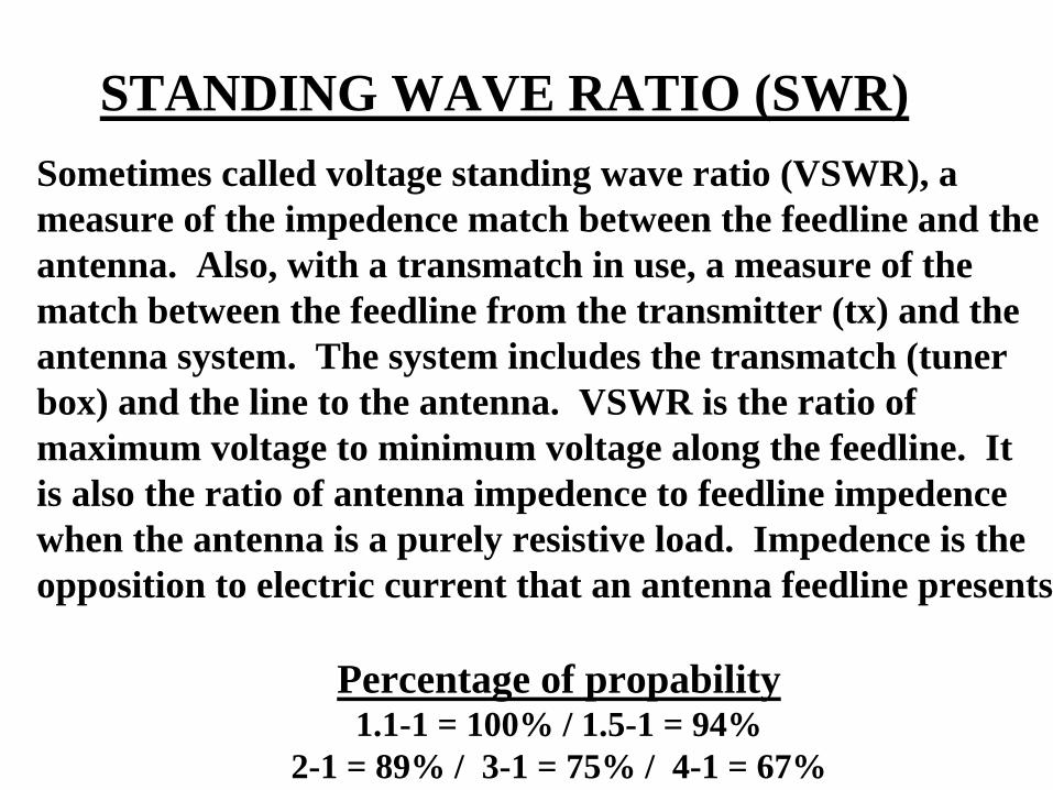
STANDING WAVE RATIO (SWR)Sometimes called voltage standing wave ratio (VSWR), a measure of the impedence match between the feedline and theantenna. Also, with a transmatch in use, a measure of the match between the feedline from the transmitter (tx) and theantenna system. The system includes the transmatch (tunerbox) and the line to the antenna. VSWR is the ratio of maximum voltage to minimum voltage along the feedline. Itis also the ratio of antenna impedence to feedline impedencewhen the antenna is a purely resistive load. Impedence is theopposition to electric current that an antenna feedline presents.
Percentage of propability1.1-1 = 100% / 1.5-1 = 94%
2-1 = 89% / 3-1 = 75% / 4-1 = 67%
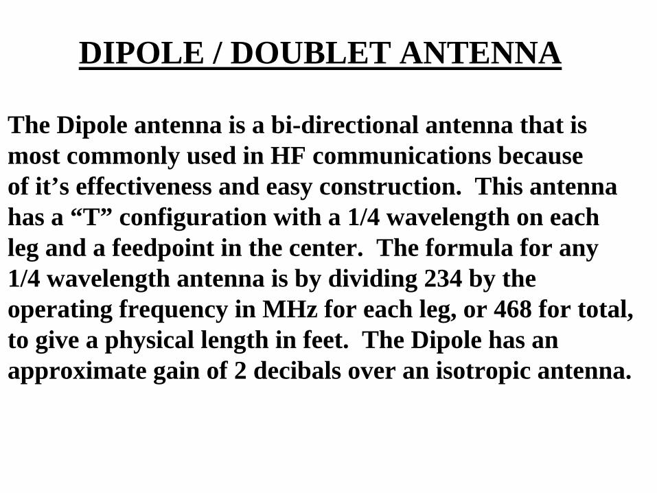
DIPOLE / DOUBLET ANTENNA
The Dipole antenna is a bi-directional antenna that ismost commonly used in HF communications becauseof it’s effectiveness and easy construction. This antennahas a “T” configuration with a 1/4 wavelength on eachleg and a feedpoint in the center. The formula for any 1/4 wavelength antenna is by dividing 234 by the operating frequency in MHz for each leg, or 468 for total, to give a physical length in feet. The Dipole has an approximate gain of 2 decibals over an isotropic antenna.
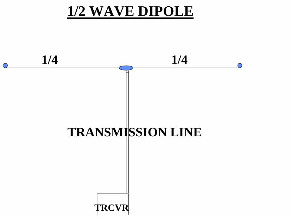
1/2 WAVE DIPOLE
1/4 1/4
TRANSMISSION LINE
TRCVR
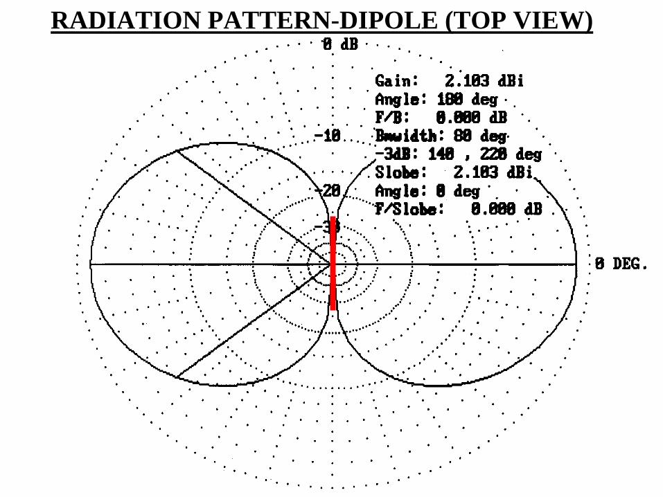
RADIATION PATTERN-DIPOLE (TOP VIEW)
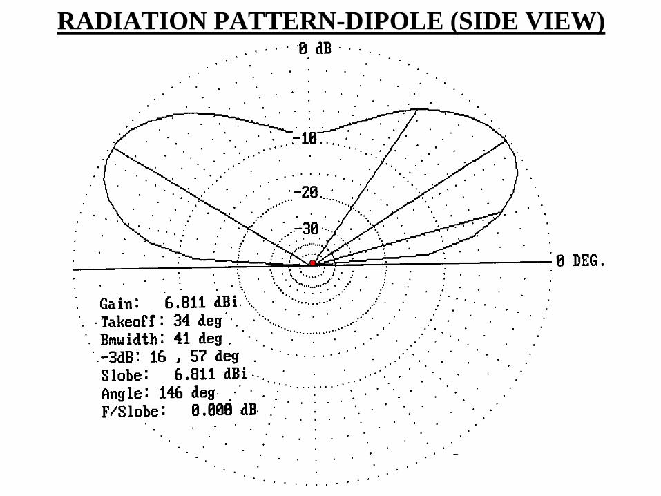
RADIATION PATTERN-DIPOLE (SIDE VIEW)

1/4 1/4
ELECTRICIANS KNOT DIPOLE
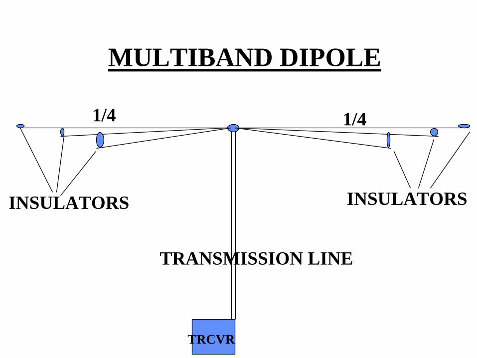
MULTIBAND DIPOLE
TRCVR
INSULATORS INSULATORS
1/4 1/4
TRANSMISSION LINE
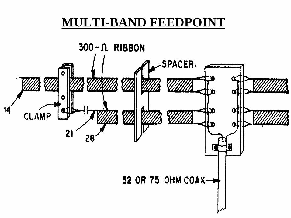
MULTI-BAND FEEDPOINT
INVERTED V ANTENNA
The inverted V antenna is also a 1/4 wavelength antennabut like the Dipole, the legs are brought down to form a “V” configuration. It is also bi-directional unless both legs are close together and a 400-600 Ohm resister is placed on the ends of the legs. This is also a preferredantenna because of it’s easy construction, and unlike thedipole it only needs one form of support.
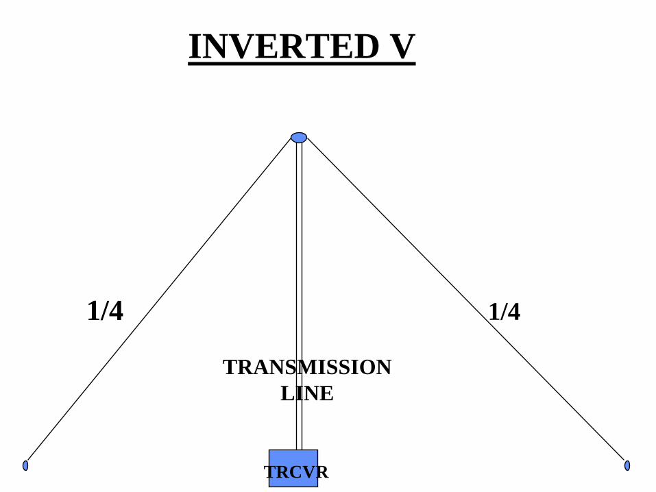
INVERTED V
1/4 1/4
TRCVR
TRANSMISSION LINE
SLANT ANTENNA
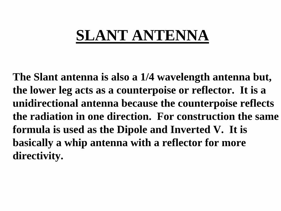
The Slant antenna is also a 1/4 wavelength antenna but,the lower leg acts as a counterpoise or reflector. It is a unidirectional antenna because the counterpoise reflectsthe radiation in one direction. For construction the sameformula is used as the Dipole and Inverted V. It isbasically a whip antenna with a reflector for more directivity.
COUNTERPOISE
1/4
SLANTINSULATOR
TRCVR

LOOP ANTENNA
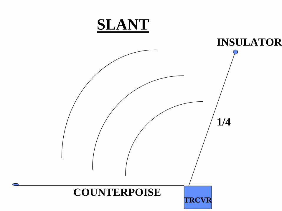
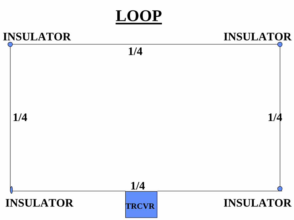
The Loop antenna unlike the Dipole, is a one wavelength antenna. It is often used indoors because of the supportsneeded. To find the length in feet, divide 1,005 by theoperating frequency. There are several configurationsfor this antenna such as, Quad loop, Diamond loop, andDelta loop. The Quad and Diamond have 4 sides just divide the length by 4 to get each side, and the Delta has3 sides. This antenna can either be horizontal or verticaleach having a different radiation pattern.
1/4
1/4 1/4
1/4
LOOPINSULATOR INSULATOR
INSULATOR INSULATORTRCVR
LONGWIRE ANTENNA
The Longwire is an antenna that’s total length is over 1wavelength long. Unlike the dipole, it’s energy is radiatedapproximately 15 degrees off the end not broadside likethe others. Because it is more than 1 wavelength long, thewave travels along the length of the wire. The formula forconstructing a longwire is multiply 492 times the numberof desired wavelengths, minus 5% and divide by the operating frequency. This type of antenna can also be used with a counterpoise and made more directional witha 400-600 Ohm resistor on the end.
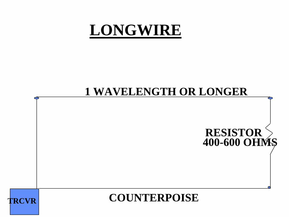
RESISTOR400-600 OHMS
1 WAVELENGTH OR LONGER
TRCVR
LONGWIRE
COUNTERPOISE

REFLECTOR
RADIATOR
DIRECTORSFEEDPOINT
YAGI5%
DIFFERENCE
1/4 1/4

RADIATION PATTERN-YAGI (SIDE VIEW)
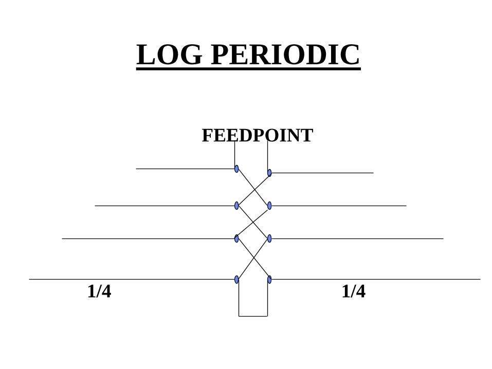
FEEDPOINT
LOG PERIODIC
1/4 1/4
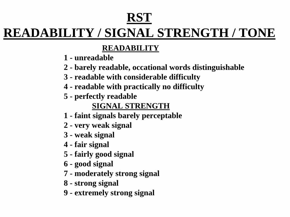
RSTREADABILITY / SIGNAL STRENGTH / TONE
READABILITY 1 - unreadable2 - barely readable, occational words distinguishable3 - readable with considerable difficulty4 - readable with practically no difficulty5 - perfectly readable
SIGNAL STRENGTH1 - faint signals barely perceptable2 - very weak signal3 - weak signal4 - fair signal5 - fairly good signal6 - good signal7 - moderately strong signal8 - strong signal9 - extremely strong signal

RSTREADABILITY / SIGNAL STRENGTH / TONE
TONE (CW)1 - sixty-cycle ac or less, very rough and broad2 - very rough ac, very harsh and broad3 - rough ac tone, rectified but not filtered4 - rough note, some trace of filtering5 - filtered rectified ac but strongly ripple modulation6 - filtered tone, definate trace of ripple modulation7 - near pure tone, trace of ripple modulation8 - near perfect tone, slight trace of modulation9 - perfect tone, no trace of ripple modulation
RST = 599
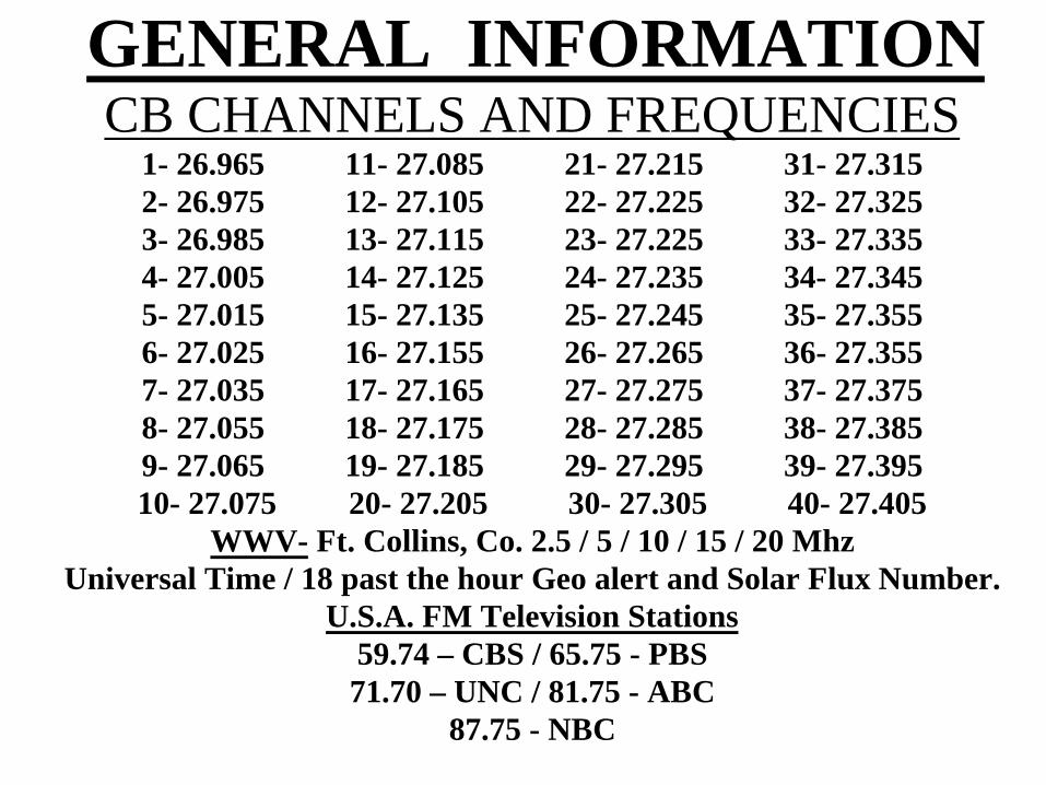
GENERAL INFORMATIONCB CHANNELS AND FREQUENCIES
1- 26.965 11- 27.085 21- 27.215 31- 27.3152- 26.975 12- 27.105 22- 27.225 32- 27.3253- 26.985 13- 27.115 23- 27.225 33- 27.3354- 27.005 14- 27.125 24- 27.235 34- 27.3455- 27.015 15- 27.135 25- 27.245 35- 27.3556- 27.025 16- 27.155 26- 27.265 36- 27.3557- 27.035 17- 27.165 27- 27.275 37- 27.3758- 27.055 18- 27.175 28- 27.285 38- 27.3859- 27.065 19- 27.185 29- 27.295 39- 27.39510- 27.075 20- 27.205 30- 27.305 40- 27.405
WWV- Ft. Collins, Co. 2.5 / 5 / 10 / 15 / 20 MhzUniversal Time / 18 past the hour Geo alert and Solar Flux Number.
U.S.A. FM Television Stations59.74 – CBS / 65.75 - PBS71.70 – UNC / 81.75 - ABC
87.75 - NBC