anthony power joist® - trussspecialists.com · 1. before laying out floor system components,...
TRANSCRIPT

ANTHONY Power Joist®Storage and Handling Guidelines1. Store, stack, and handle Power Joist in a vertical and level position only.
2. Do not store Power Joists in direct contact with the ground; Do not store Power Joists flatwise.
3. Protect Power Joists from weather, and use stickers to separate bundles.
4. To protect Power Joists further from dirt and weather, do not open bun-dles until time of installation.
5. When lifting Power Joists with a crane on the job site, take a few simple precautions to prevent damage to the Power Joists and to prevent injury to your work crew.
n Lift Power Joists in bundles as shipped by the supplier.
n Orient the bundles so that the webs of the Power Joists are vertical.
n Lift the bundles at the 5th points, using a spreader bar if necessary.
6. Do not twist or apply loads to the Power Joist when horizontal.
7. Never use or try to repair a damaged Power Joist.
Safety Precautions WARNING Power Joists are not stable until completely installed and will not carry any load until fully braced and sheathed.
Avoid Accidents by Following These Important Guidelines.1. Brace and nail each Power Joist as it is installed, using hangers, blocking
panels, rim board, and/or cross-bridging at joist ends. When Power Joists are applied continuously over interior supports and a load-bearing wall is planned at the location, blocking will be required at the interior supports.
2. When the building is completed, the floor sheathing will provide lateral support for the top flanges of the Power Joists. Until this sheathing is applied, temporary bracing, often called struts, or temporary sheathing must be applied to prevent Power Joist rollover or buckling.
�n Temporary bracing or struts must be 1” x 4” minimum, at least 8’ long, spaced no more than 8’ on center, and secured with a minimum of two 8d nails fastened to the top surface of each Power Joist. Nail bracing to a lateral restraint at the end of each bay. Lap ends of adjoining bracing over at least two Power Joists.
�n Or, sheathing (temporary or permanent) can be nailed to the top flange of the first 4’ of Power Joists at the end of the bay.
3. For cantilevered Power Joists, brace top and bottom flanges, and brace ends with closure panels, rim board, or cross-bridging.
4. Install and nail permanent sheathing to each Power Joist before placing loads on the floor system. Then, stack building materials over beams or walls only.
5. For temporary construction loads such as dry wall stacking, see APA Publication J735A (Temporary Construction Loads Over I-Joist Roofs).
Failure to follow applicable building codes and span ratings, failure to use allowable hole sizes and locations, or failure to use web stiffeners when required can result in serious accidents. Follow these installation guidelines carefully.
LL 5
L 5
Never stack building materials over unsheathed
Power Joists. Stack only over beams or walls.
Do not allow workers to walk on Power Joists
until joists are fully installed and braced, or serious inju-
ries can result.
U n i t e d S tat e S i n S ta l l at i o n G U i d e ( i C C e S R - 1 2 6 2 )
Manufactured by anthony eacoM, Inc.february 2014
Allowable Floor Spans
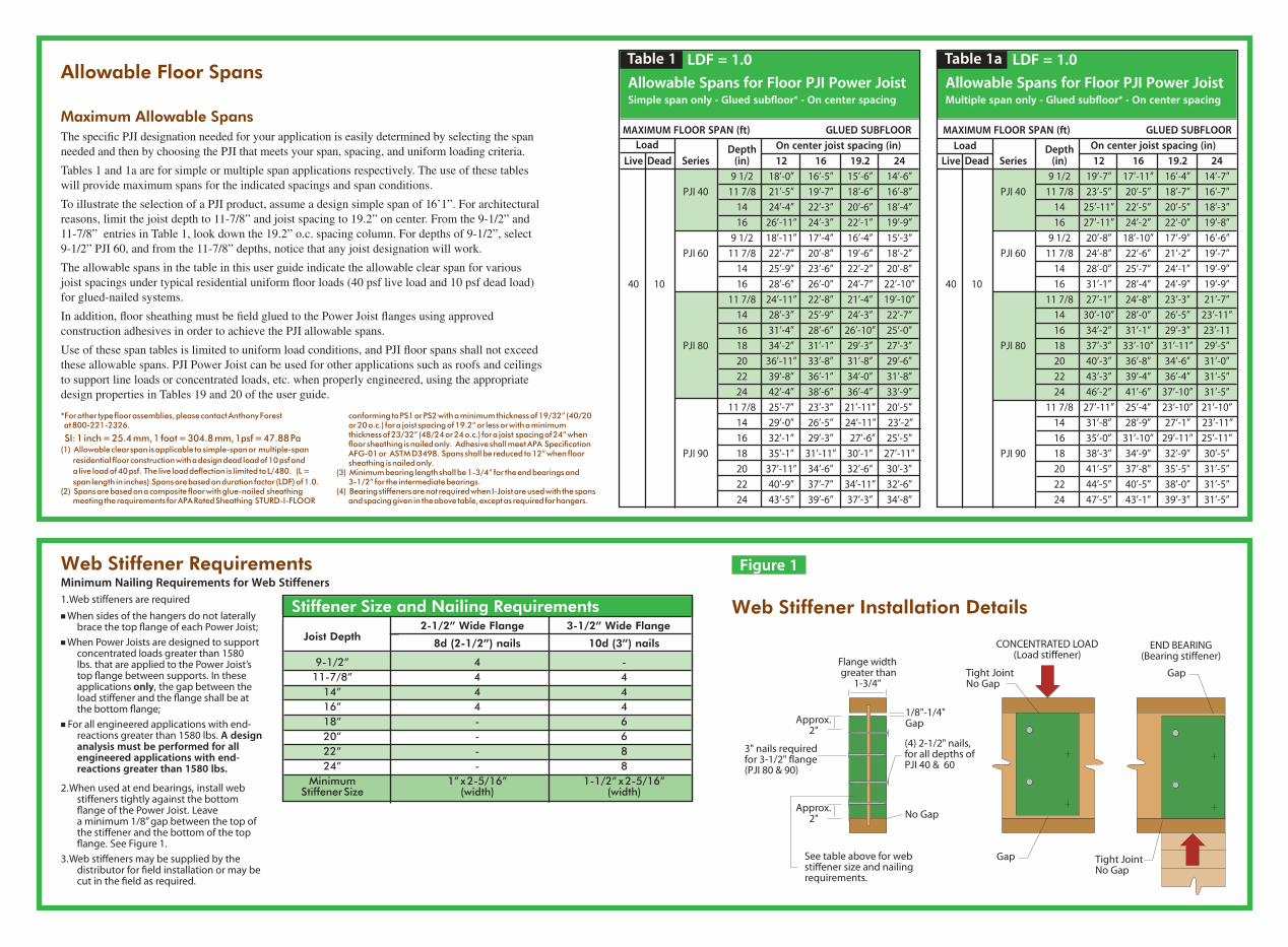
Maximum Allowable SpansThe specific PJI designation needed for your application is easily determined by selecting the span needed and then by choosing the PJI that meets your span, spacing, and uniform loading criteria.
Tables 1 and 1a are for simple or multiple span applications respectively. The use of these tables will provide maximum spans for the indicated spacings and span conditions.
To illustrate the selection of a PJI product, assume a design simple span of 16’1”. For architectural reasons, limit the joist depth to 11‑7/8” and joist spacing to 19.2” on center. From the 9‑1/2” and 11‑7/8” entries in Table 1, look down the 19.2” o.c. spacing column. For depths of 9‑1/2”, select 9‑1/2” PJI 60, and from the 11‑7/8” depths, notice that any joist designation will work.
The allowable spans in the table in this user guide indicate the allowable clear span for various joist spacings under typical residential uniform floor loads (40 psf live load and 10 psf dead load) for glued‑nailed systems.
In addition, floor sheathing must be field glued to the Power Joist flanges using approved construction adhesives in order to achieve the PJI allowable spans.
Use of these span tables is limited to uniform load conditions, and PJI floor spans shall not exceed these allowable spans. PJI Power Joist can be used for other applications such as roofs and ceilings to support line loads or concentrated loads, etc. when properly engineered, using the appropriate design properties in Tables 19 and 20 of the user guide.
*For other type floor assemblies, please contact Anthony Forest at 800-221-2326. SI: 1 inch = 25.4 mm, 1 foot = 304.8 mm, 1psf = 47.88 Pa(1) Allowable clear span is applicable to simple-span or multiple-span
residential floor construction with a design dead load of 10 psf and a live load of 40 psf. The live load deflection is limited to L/480. (L = span length in inches).Spans are based on duration factor (LDF) of 1.0.
(2) Spans are based on a composite floor with glue-nailed sheathing meeting the requirements for APA Rated Sheathing STURD-I-FLOOR
conforming to PS1 or PS2 with a minimum thickness of 19/32” (40/20 or 20 o.c.) for a joist spacing of 19.2” or less or with a minimum thickness of 23/32” (48/24 or 24 o.c.) for a joist spacing of 24” when floor sheathing is nailed only. Adhesive shall meet APA Specification AFG-01 or ASTM D3498. Spans shall be reduced to 12” when floor sheathing is nailed only.
(3) Minimum bearing length shall be 1-3/4” for the end bearings and 3-1/2” for the intermediate bearings.(4) Bearing stiffeners are not required when I-Joist are used with the spans
and spacing given in the above table, except as required for hangers.
Stiffener Size and Nailing Requirements 2-1/2” Wide Flange 3-1/2” Wide Flange
Joist Depth
8d (2-1/2”) nails 10d (3”) nails
9-1/2” 4 - 11-7/8” 4 4 14” 4 4 16” 4 4 18” - 6 20” - 6 22” - 8 24” - 8 Minimum 1” x 2-5/16” 1-1/2” x 2-5/16” Stiffener Size (width) (width)
Web Stiffener RequirementsMinimum Nailing Requirements for Web Stiffeners1. Web stiffeners are required
n When sides of the hangers do not laterally brace the top flange of each Power Joist;
n When Power Joists are designed to support concentrated loads greater than 1580 lbs. that are applied to the Power Joist’s top flange between supports. In these applications only, the gap between the load stiffener and the flange shall be at the bottom flange;
n For all engineered applications with end-reactions greater than 1580 lbs. A design analysis must be performed for all engineered applications with end-reactions greater than 1580 lbs.
2. When used at end bearings, install web stiffeners tightly against the bottom flange of the Power Joist. Leave a minimum 1/8” gap between the top of the stiffener and the bottom of the top flange. See Figure 1.
3. Web stiffeners may be supplied by the distributor for field installation or may be cut in the field as required.
Gap
Tight JointNo Gap
CONCENTRATED LOAD(Load stiffener)
END BEARING(Bearing stiffener)
Approx.2"
Approx.2"
See table above for web stiffener size and nailingrequirements.
1/8"-1/4" Gap
Tight JointNo Gap
Gap
No Gap
(4) 2-1/2" nails,for all depths of PJI 40 & 60
3" nails requiredfor 3-1/2" flange(PJI 80 & 90)
Flange width greater than
1-3/4"
Figure 1 Continued
Web Stiffener Installation Details
Load Load
Allowable Spans for Floor PJI Power JoistSimple span only - Glued subfloor* - On center spacing
MAXIMUM FLOOR SPAN (ft) GLUED SUBFLOOR
Depth On center joist spacing (in)
Live Dead Series (in) 12 16 19.2 24
9 1/2 18’-0” 16’-5” 15’-6” 14’-6”
PJI 40 11 7/8 21’-5” 19’-7” 18’-6” 16’-8”
14 24’-4” 22’-3” 20’-6” 18’-4”
16 26’-11” 24’-3” 22’-1” 19’-9”
9 1/2 18’-11” 17’-4” 16’-4” 15’-3”
PJI 60 11 7/8 22’-7” 20’-8” 19’-6” 18’-2”
14 25’-9” 23’-6” 22’-2” 20’-8”
40 10 16 28’-6” 26’-0” 24’-7” 22’-10”
11 7/8 24’-11” 22’-8” 21’-4” 19’-10”
14 28’-3” 25’-9” 24’-3” 22’-7”
16 31’-4” 28’-6” 26’-10” 25’-0”
PJI 80 18 34’-2” 31’-1” 29’-3” 27’-3”
20 36’-11” 33’-8” 31’-8” 29’-6”
22 39’-8” 36’-1” 34’-0” 31’-8”
24 42’-4” 38’-6” 36’-4” 33’-9”
11 7/8 25’-7” 23’-3” 21’-11” 20’-5”
14 29’-0” 26’-5” 24’-11” 23’-2”
16 32’-1” 29’-3” 27’-6” 25’-5”
PJI 90 18 35’-1” 31’-11” 30’-1” 27’-11”
20 37’-11” 34’-6” 32’-6” 30’-3”
22 40’-9” 37’-7” 34’-11” 32’-6”
24 43’-5” 39’-6” 37’-3” 34’-8”
Table 1 LDF = 1.0 LDF = 1.0Table 1a
Allowable Spans for Floor PJI Power JoistMultiple span only - Glued subfloor* - On center spacing
MAXIMUM FLOOR SPAN (ft) GLUED SUBFLOOR
Depth On center joist spacing (in)
Live Dead Series (in) 12 16 19.2 24
9 1/2 19’-7” 17’-11” 16’-4” 14’-7”
PJI 40 11 7/8 23’-5” 20’-5” 18’-7” 16’-7”
14 25’-11” 22’-5” 20’-5” 18’-3”
16 27’-11” 24’-2” 22’-0” 19’-8”
9 1/2 20’-8” 18’-10” 17’-9” 16’-6”
PJI 60 11 7/8 24’-8” 22’-6” 21’-2” 19’-7”
14 28’-0” 25’-7” 24’-1” 19’-9”
40 10 16 31’-1” 28’-4” 24’-9” 19’-9”
11 7/8 27’-1” 24’-8” 23’-3” 21’-7”
14 30’-10” 28’-0” 26’-5” 23’-11”
16 34’-2” 31’-1” 29’-3” 23’-11
PJI 80 18 37’-3” 33’-10” 31’-11” 29’-5”
20 40’-3” 36’-8” 34’-6” 31’-0”
22 43’-3” 39’-4” 36’-4” 31’-5”
24 46’-2” 41’-6” 37’-10” 31’-5”
11 7/8 27’-11” 25’-4” 23’-10” 21’-10”
14 31’-8” 28’-9” 27’-1” 23’-11”
16 35’-0” 31’-10” 29’-11” 25’-11”
PJI 90 18 38’-3” 34’-9” 32’-9” 30’-5”
20 41’-5” 37’-8” 35’-5” 31’-5”
22 44’-5” 40’-5” 38’-0” 31’-5”
24 47’-5” 43’-1” 39’-3” 31’-5”

1. Before laying out floor system components, verify that Power Joist flange widths match hanger widths. If not, contact your supplier.
2. Except for cutting to length, never cut, drill, or notch Power Joist flanges.
3. Install Power Joists so that top and bottom flanges are within 1/2” of true vertical alignment.
4. Power Joists must be anchored securely to supports before floor sheathing is attached, and supports for multiple-span joists must be level.
5. Minimum bearing lengths are 1-3/4” for end bearings and 3-1/2” for intermediate bearings.
6. When using hangers, seat Power Joists firmly in hanger bottoms to minimize settlement.
7. Leave a 1/16” gap between the Power Joist end and a header.
8. Concentrated loads greater than those that can normally be expected in residential construction should be applied only to the top surface of the top flange. Normal concentrated loads include track lighting fixtures, audio equipment, and security cameras. Never suspend unusual or heavy loads from the Power Joist’s bottom flange. Whenever possible, suspend all concentrated loads from the top of the Power Joist, or attach the load to blocking that has been securely fastened to the Power Joist webs.
9. Never install Power Joists where they will be permanently exposed to weather or where they will remain in direct contact with concrete or masonry.
10. Restrain ends of floor joists to prevent rollover. Use Certified Rim Board, rim joists, or Power Joist blocking panels.
11. For Power Joists installed over and beneath bearing walls, use full depth blocking panels, Certified Rim Board, or squash blocks (cripple members) to transfer gravity loads through the floor system to the wall or foundation below.
12. Due to shrinkage, common framing lumber set on edge may never be used as blocking or rim boards. Power Joist blocking panels or other engineered wood products such as Certified Rim Board must be cut to fit between the Power Joists, and a Power Joist-compatible depth must be selected.
13. Provide permanent lateral support of the bottom flange of all Power Joists at interior supports of multiple-span joists. Similarly, support the bottom flange of all cantilevered Power Joists at the end support next to the cantilever extension. In the completed structure, the gypsum wallboard ceiling provides this lateral support. Until the final finished ceiling is applied, temporary bracing or struts must be used.
14. If square-edge panels are used, edges must be supported between Power Joists with 2 x 4 blocking. Glue panels to blocking to minimize squeaks. Blocking is not required under structural finish flooring such as wood strip flooring or if a separate underlayment layer is installed.
15. Nail spacing Space the nails installed to the flange’s top face in accordance with the applicable building code requirements or approved building plans.
Installing Power Joist Figure 2
Typical PJI Power Joist Floor Framing and Construction Details
Holes may be cut in web forplumbing, wiring, and duct work.See Table 3 and Figure 7.
Figures 3, 4, 5, and 6
Figures 3, 4, 5 and 6
Use hangers recognized in current ICC-ES reports.
Glulam or Structural Composite Lumber (SCL) headers
NOTE Never cut or notch flanges.
Glulam or SCL headers
Some framing requirements such as erection bracing and blocking panels have been omitted for clarity.
2k 2m2j2h
2f2n2a
2g
2e
2j
2c2b
2d
2p
2b Rim Board Detail
APA Rim Board
One 8d common or box nail at top and bottom flange
Attach APA Rim Board to top plate using 8d common or box toenails @ 6" o.c.
One 8d face nail at each side at bearing
To avoid splitting flange, start nails at least 1-1/2" from end of Power Joist. Nails may be driven at an angle to avoid splitting of bearing plate.
Blocking Panel or Rim Joist Uniform Vertical Load Transfer Capacity* (plf)
1-1/8" APA Rim Board Plus 48501-1/8" APA Rim Board 44001" APA Rim Board 3300
*The uniform vertical load capacity is limited to Rim Board depth of 18” or less and is based on the normal (10-yr) load duration. It shall not be used in the design of a bending member such as joist, header, or rafter. For concentrated vertical load transfer capacity, see 2d.
2a
Attach Power Joistto top plate per 2b.
8d nails @ 6" o.c. to top plate (when used for lateral shear transfer, nail to bearing plate with same nailing as required for decking)
PJI blockingpanel
Blocking Panel or Rim Joist Uniform Vertical Load Transfer Capacity* (plf)
PJI Joists (9 1/2 - 18”) 2000
*The uniform vertical load capacity is limited to a joist depth of 18” or less and is based on the normal (10-yr) load duration. It shall not be used in the design of a bending member such as joist, header, or rafter. For concentrated vertical load transfer capacity, see 2d.
Blocking Panel at End Support Detail2c PJI as
Rim Joist Detail
Attach rim joist to top plate per 2a.
PJI rim joist per 2a
Attach rim joist to floor joist with one nail at top and bottom. Nail must provide 1" minimum penetration into floor joist. For 2-1/2" and 3-1/2" flange widths, toenails may be used.
Minimum 1-3/4" bearing required
Attach Power Joist per 2b.
2d Squash Block Detail
Squash block Provide lateral bracing per 2a, 2b, or 2c.
APA Rim Board blocking panel per 2a
+ 1/16"for squashblocks
Vertical load transfer capacity per pair of squash blocks (lb) Pair of Squash Blocks 3-1/2" wide 5-1/2" wide 2x lumber 3800 5900 1-1/8" APA Rim Board, Rim Board Plus, or 2600 4000 Rated Sturd-I-Floor 48 oc 1" APA Rim Board or Rated Sturd-I-Floor 32 oc
1900 3000
All nails shown in the details below are assumed to be common nails unless otherwise noted. 10d box nails (0.128 x 3”) may be substituted for 8d common (0.131 x 2-1/2”) as shown in details. Individual components are not shown to scale for clarity.
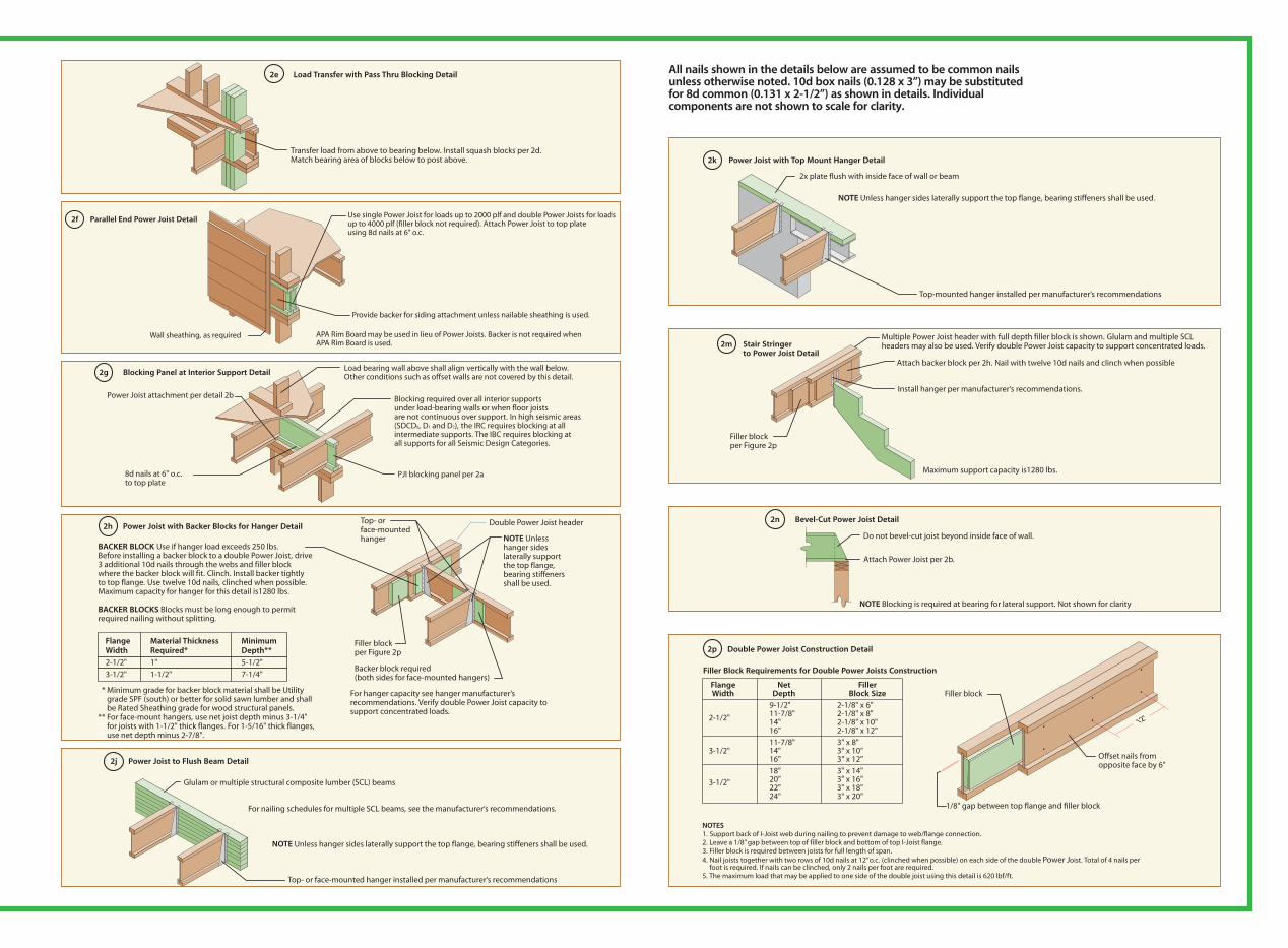
2e Load Transfer with Pass Thru Blocking Detail
Transfer load from above to bearing below. Install squash blocks per 2d. Match bearing area of blocks below to post above.
2f Parallel End Power Joist Detail
APA Rim Board may be used in lieu of Power Joists. Backer is not required when APA Rim Board is used.
Provide backer for siding attachment unless nailable sheathing is used.
Wall sheathing, as required
Use single Power Joist for loads up to 2000 plf and double Power Joists for loadsup to 4000 plf (filler block not required). Attach Power Joist to top plateusing 8d nails at 6" o.c.
2g Blocking Panel at Interior Support Detail
PJI blocking panel per 2a
Blocking required over all interior supports under load-bearing walls or when floor joists are not continuous over support. In high seismic areas (SDCD0, D1 and D2), the IRC requires blocking at all intermediate supports. The IBC requires blocking atall supports for all Seismic Design Categories.
8d nails at 6" o.c.to top plate
Power Joist attachment per detail 2b
Load bearing wall above shall align vertically with the wall below. Other conditions such as offset walls are not covered by this detail.
2h Power Joist with Backer Blocks for Hanger Detail
Flange Material Thickness Minimum Width Required* Depth**
2-1/2" 1" 5-1/2"
3-1/2" 1-1/2" 7-1/4"
BACKER BLOCK Use if hanger load exceeds 250 lbs. Before installing a backer block to a double Power Joist, drive 3 additional 10d nails through the webs and filler block where the backer block will fit. Clinch. Install backer tightly to top flange. Use twelve 10d nails, clinched when possible. Maximum capacity for hanger for this detail is1280 lbs.
BACKER BLOCKS Blocks must be long enough to permit required nailing without splitting.
** Minimum grade for backer block material shall be Utility ** grade SPF (south) or better for solid sawn lumber and shall** be Rated Sheathing grade for wood structural panels.** For face-mount hangers, use net joist depth minus 3-1/4" ** for joists with 1-1/2" thick flanges. For 1-5/16" thick flanges, ** use net depth minus 2-7/8".
Backer block required (both sides for face-mounted hangers)
For hanger capacity see hanger manufacturer’s recommendations. Verify double Power Joist capacity to support concentrated loads.
Filler blockper Figure 2p
Double Power Joist headerTop- or face-mounted hanger NOTE Unless
hanger sides laterally support the top flange, bearing stiffeners shall be used.
2k Power Joist with Top Mount Hanger Detail
2x plate flush with inside face of wall or beam
Top-mounted hanger installed per manufacturer‘s recommendations
NOTE Unless hanger sides laterally support the top flange, bearing stiffeners shall be used.
2m Stair Stringer to Power Joist Detail
Filler blockper Figure 2p
Attach backer block per 2h. Nail with twelve 10d nails and clinch when possible
Maximum support capacity is1280 lbs.
Install hanger per manufacturer‘s recommendations.
Multiple Power Joist header with full depth filler block is shown. Glulam and multiple SCL headers may also be used. Verify double Power Joist capacity to support concentrated loads.
2n Bevel-Cut Power Joist Detail
Do not bevel-cut joist beyond inside face of wall.
NOTE Blocking is required at bearing for lateral support. Not shown for clarity
Attach Power Joist per 2b.
2p Double Power Joist Construction Detail
1/8" gap between top flange and filler block
Filler block
Offset nails from opposite face by 6"
NOTES1. Support back of I-Joist web during nailing to prevent damage to web/flange connection.2. Leave a 1/8” gap between top of filler block and bottom of top I-Joist flange.3. Filler block is required between joists for full length of span.4. Nail joists together with two rows of 10d nails at 12” o.c. (clinched when possible) on each side of the double Power Joist. Total of 4 nails per
foot is required. If nails can be clinched, only 2 nails per foot are required.5. The maximum load that may be applied to one side of the double joist using this detail is 620 lbf/ft.
12"
Flange Net Filler Width Depth Block Size
9-1/2" 2-1/8" x 6"
2-1/2" 11-7/8" 2-1/8" x 8" 14" 2-1/8" x 10" 16" 2-1/8" x 12"
11-7/8" 3" x 8"3-1/2" 14" 3" x 10" 16" 3" x 12"
18" 3" x 14"
3-1/2" 20" 3" x 16" 22" 3" x 18" 24" 3" x 20"
Filler Block Requirements for Double Power Joists Construction
Installing Power Joist All nails shown in the details below are assumed to be common nails unless otherwise noted. 10d box nails (0.128 x 3”) may be substituted for 8d common (0.131 x 2-1/2”) as shown in details. Individual components are not shown to scale for clarity.
2j Power Joist to Flush Beam Detail
Glulam or multiple structural composite lumber (SCL) beams
For nailing schedules for multiple SCL beams, see the manufacturer‘s recommendations.
NOTE Unless hanger sides laterally support the top flange, bearing stiffeners shall be used.
Top- or face-mounted hanger installed per manufacturer‘s recommendations

Table 2PJI Cantilever Reinforcement Methods Allowed
ROOF LOADINGSRoof TL = 35 psf TL = 45 psf TL = 55 psf
Joist Truss LL not to exceed 20 psf LL not to exceed 30 psf LL not to exceed 40 psfDepth Span Joist Spacing (in.) Joist Spacing (in.) Joist Spacing (in.)
(in.) (ft) 12 16 19.2 24 12 16 19.2 24 12 16 19.2 2426 N N N 1,2 N N 1,2 2 N 1,2 2 X28 N N 1,2 1,2 N N 1,2 2 N 1,2 2 X30 N N 2 1,2 N 1,2 1,2 2 N 1,2 2 X9-1/232 N N 1,2 2 N 1,2 1,2 X N 1,2 2 X34 N N 1,2 2 N 1,2 2 X N 2 X X36 N N 1,2 2 N 1,2 2 X N 2 X X26 N N N 1,2 N N 1,2 1,2 N 1,2 1,2 228 N N 1,2 1,2 N 1,2 1,2 1,2 N 1,2 1,2 230 N N 1,2 1,2 N 1,2 1,2 2 N 1,2 1,2 2
11-7/8 32 N N 1,2 1,2 N 1,2 1,2 2 N 1,2 1,2 234 N N 1,2 1,2 N 1,2 1,2 2 N 1,2 2 236 N N 1,2 1,2 N 1,2 1,2 2 N 1,2 2 238 N 1,2 1,2 2 N 1,2 1,2 2 1,2 1,2 2 X26 N N N 1,2 N N N 1,2 N N 1,2 1,228 N N N 1,2 N N 1,2 1,2 N N 1,2 230 N N N 1,2 N N 1,2 1,2 N 1,2 1,2 232 N N N 1,2 N N 1,2 1,2 N 1,2 1,2 21434 N N N 1,2 N N 1,2 2 N 1,2 1,2 236 N N 1,2 1,2 N 1,2 1,2 2 N 1,2 1,2 238 N N 1,2 1,2 N 1,2 1,2 2 N 1,2 1,2 240 N N 1,2 1,2 N 1,2 1,2 2 N 1,2 2 226 N N N 1,2 N N 1,2 1,2 N N 1,2 1,228 N N N 1,2 N N 1,2 1,2 N 1,2 1,2 230 N N N 1,2 N N 1,2 1,2 N 1,2 1,2 232 N N N 1,2 N N 1,2 1,2 N 1,2 1,2 2
16 34 N N 1,2 1,2 N N 1,2 2 N 1,2 1,2 236 N N 1,2 1,2 N 1,2 1,2 2 N 1,2 1,2 238 N N 1,2 1,2 N 1,2 1,2 2 N 1,2 2 240 N N 1,2 1,2 N 1,2 1,2 2 N 1,2 2 242 N N 1,2 1,2 N 1,2 1,2 2 N 1,2 2 X
Cantilever Reinforcement Methods
Project1:Layout 1 9/29/08 1:49 PM Page 1
Cantilever Detail for Vertical Building Offset(Concentrated Wall Load)
Figure 3a
See Table below for Power Joist reinforcement requirements at cantilever.
For hip roofs with the hip trusses running parallel to the cantilevered floor joists, the Power Joist reinforcement requirements for a span of 26 ft. shall be permitted to be used.
2'–0" maximumcantilever
Roof truss span
2'–0" maximumcantilever
Hip trussesGirder
truss
Roof trusses 13'–0" maximum
Roof truss span
NOTES(1) N = No reinforcement required 1 = PJIs reinforced with 23/32” wood structural panel on one side only 2 = PJIs reinforced with 23/32” wood structural panel on both sides or double Power Joist X = Try a deeper joist or closer spacing.(2) Color coding in table is matched to details in Figure 6.(3) Maximum load shall be 15 psf roof dead load, 50 psf floor total load, and
80 plf wall load. Wall load is based on 3’–0” maximum width window or door openings. For larger openings or multiple 3’–0” width openings
spaced less than 6’–0” o.c., additional joists beneath the opening’s cripple studs may be required.
(4) Table applies to joists 12” to 24” o.c. Use 12” o.c. requirements for lesser spacings.
(5) For conventional roof construction using a ridge beam, the Roof Truss Span column above is equivalent to the distance between the supporting wall and the ridge beam. When the roof is framed using a ridge board, the Roof Truss Span is equivalent to the distance between the supporting walls as if a truss is used.
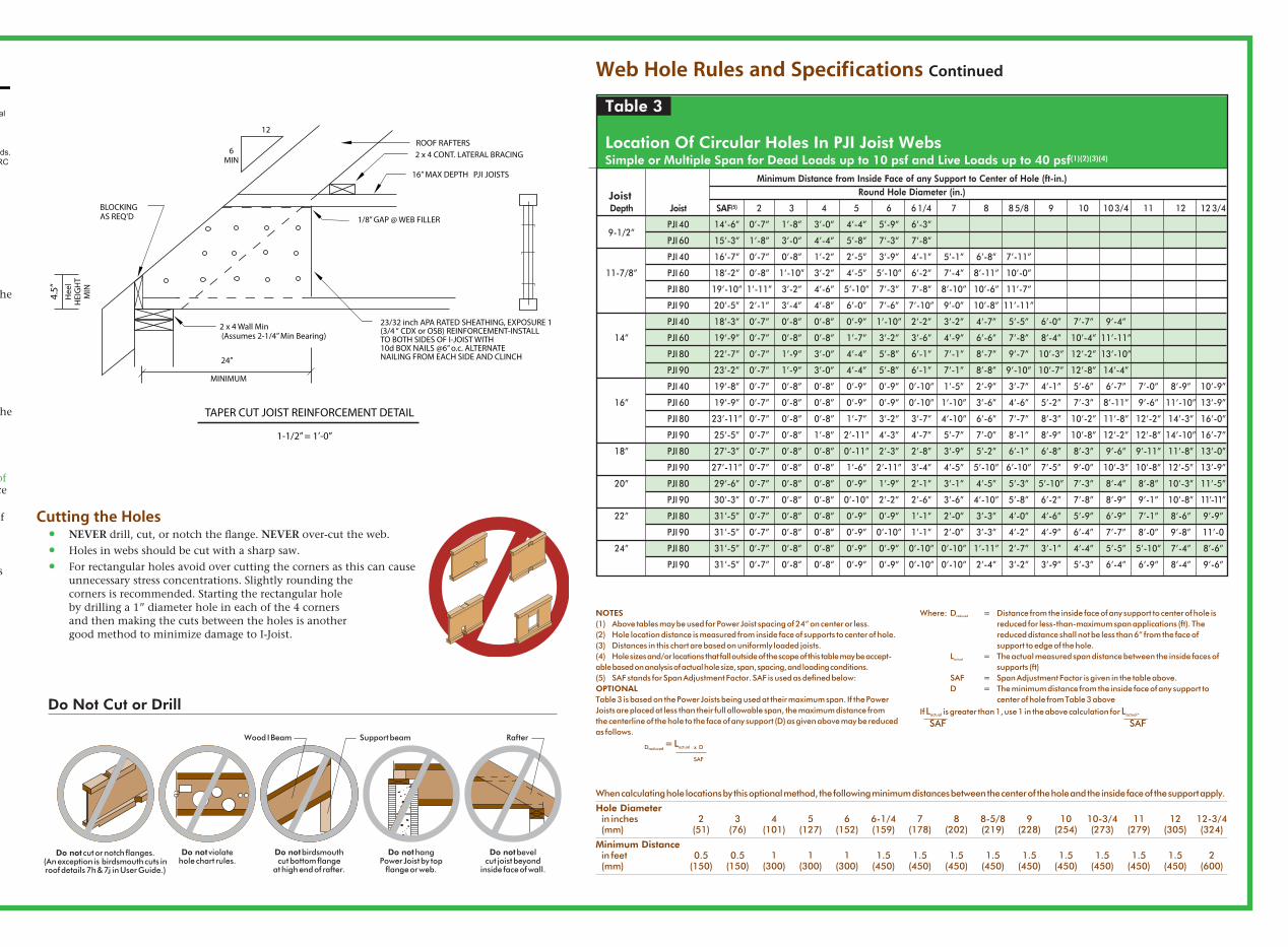
Web Hole Rules and SpecificationsOne of the benefits of using Power Joists in residential floor construction is that holes may be cut in the joist webs to accommodate electrical wiring, plumbing lines, and other mechanical systems thereby minimizing the depth of the floor system.
Rules for Cutting Holes in PJI Joists 11. The distance between the inside edge of the support and the centerline of any hole shall be in
compliance with the requirements of Table 3. 12. Power Joist top and bottom flanges must NEVER be cut, notched, or otherwise modified. 13. Whenever possible field-cut holes should be centered on the middle of the web. 14. The maximum size hole that can be cut into a Power Joist web shall equal the clear distance between
the flanges of the Power Joist minus 1/4”. A minimum of 1/8” should always be maintained between the top or bottom of the hole and the adjacent Power Joist flange.
15. The sides of square holes or longest sides of rectangular holes should not exceed three fourths of the diameter of the maximum round hole permitted at that location.
16. Where more than one hole is necessary, the distance between adjacent hole edges shall exceed twice the diameter of the largest round hole or twice the size of the largest square hole (or twice the length of the longest side of the longest rectangular hole) and each hole must be sized and located in compliance with the requirements of Table 3.
17. Holes measuring 1-1/2” shall be permitted anywhere in a cantilevered section of a Power Joist. Holes of greater size may be permitted subject to verification.
18. A 1-1/2” hole can be placed anywhere in the web provided that it meets the requirements of rule 6 above.
19. All holes shall be cut in a workman-like manner in accordance with the restrictions listed above and as illustrated in Figure 7.
10. Limit of 3 maximum size holes per span 11. A group of round holes at approximately the same location shall be permitted if they meet the
requirements for a single round hole circumscribed around them.
Figure 7
Power Joist Typical HolesMinimum distance from face of support to the center of hole (See Table 3.)
2x diameter of larger hole
3/4x diameter
See rule 11.
Power Joists
5 1/2" Max.
(3) 16ds at 16" on center at braced wall panels, or (1) 16d at
16" on center for other wall panels (per R602.3(1), 2006 IRC)
8d nails at 6" on center from floor sheathing into rim board
(per R602.3(1), 2006 IRC)
Rim board fastening to floor
joists:
(1) 8d face nail top and bottom
flanges each floor joist
Rim board fastening to blocking
framing:
10d face nail at 6" on center
2 x 8 blocking between each joist. Fasten to top
plate with 10d nails at 6" on center. Stagger nails.
Joist attached to supporting wall:
(2) 8d face nails – I-joist framing (fastening
not shown for clarity)
Notes:
1. The above detail is appropriate for one- and two-family residential
structures constructed in accordance with the 2006 International
Residential Code (IRC) Sections R301.2.2.2.2, R602.3(1), and
R602.10.
2. Cantilevered joists must be properly sized to support all design loads.
3. Applications that fall outside of the scope of the 2006 IRC shall be
designed in accordance with the 2006 International Building Code
(IBC).
4. Nail sizes per 2006 IRC:
8d = 2-½” x 0.113"
10d = 3" x 0.128"
16d = 3-½” x 0.135'
PJI CANTILEVER DETAIL
NOTES
Table 2PJI Cantilever Reinforcement Methods Allowed
ROOF LOADINGS Roof TL = 35 psf TL = 45 psf TL = 55 psf Joist Truss LL not to exceed 20 psf LL not to exceed 30 psf LL not to exceed 40 psf
Depth Span Joist Spacing (in.) Joist Spacing (in.) Joist Spacing (in.) (in.) (ft) 12 16 19.2 24 12 16 19.2 24 12 16 19.2 24 26 N N N 1 N N 1 2 N 1 2 X 28 N N N 1 N N 1 2 N 1 2 X 30 N N 1 1 N N 1 2 N 1 2 X
9-1/2 32 N N 1 2 N 1 1 X N 1 2 X
34 N N 1 2 N 1 2 X N 2 X X 36 N N 1 2 N 1 2 X N 2 X X 26 N N N 1 N N 1 1 N 1 1 2 28 N N 1 1 N 1 1 1 N 1 1 2 30 N N 1 1 N 1 1 2 N 1 1 2
11-7/8 32 N N 1 1 N 1 1 2 N 1 1 2 34 N N 1 1 N 1 1 2 N 1 2 2 36 N N 1 1 N 1 1 2 N 1 2 2 38 N 1 1 2 N 1 1 2 1 1 2 X 26 N N N 1 N N N 1 N N 1 1 28 N N N 1 N N 1 1 N N 1 2 30 N N N 1 N N 1 1 N 1 1 2 32 N N N 1 N N 1 1 N 1 1 2
14 34 N N N 1 N N 1 2 N 1 1 2
36 N N 1 1 N 1 1 2 N 1 1 2 38 N N 1 1 N 1 1 2 N 1 1 2 40 N N 1 1 N 1 1 2 N 1 2 2 26 N N N 1 N N 1 1 N N 1 1 28 N N N 1 N N 1 1 N N 1 2 30 N N N 1 N N 1 1 N 1 1 2 32 N N N 1 N N 1 1 N 1 1 2 16 34 N N 1 1 N N 1 2 N 1 1 2 36 N N 1 1 N 1 1 2 N 1 1 2 38 N N 1 1 N 1 1 2 N 1 1 2 40 N N 1 1 N 1 1 2 N 1 2 2 42 N N 1 1 N 1 1 2 N 1 2 X
1. The detail to the left is appropriate for one and two-family residential structures constructed in accordance with the 2006/2009/2012 International Residential Code (IRC) Sections R301.2.2.2.2, R602.3(1), and R602.10.2. Cantilevered joists must be properly sized to support all design loads.3. Applications that fall outside of the scope of the 2006/2009/2012 IRC shall be designed in accordance with the 2006/2009/2012 International Building Code (IBC). 4. Nail sizes per 2006/2009/2012 IRC: 8d = 2-1/2” x 0.113” 10d = 3” x 0.128” 16d = 3-1/2” x 0.135”
Do Not Cut or Drill
Do not violatehole chart rules.
Do not hangPower Joist by top
flange or web.
Do not bevelcut joist beyond
inside face of wall.
Do not birdsmouthcut bottom flange
at high end of rafter.
Do not cut or notch flanges.(An exception is birdsmouth cuts inroof details 7h & 7 in User Guide.)
Rafter Support beam Wood I Beam
One of the benefits of using Power Joists in residential floor construction is that holes may be cut in the joist webs to accommodate electrical wiring, plumbing lines, and other mechanical systems thereby minimizing the depth of the floor system.
Rules for Cutting Holes in PJI Joists 11. The distance between the inside edge of the support and the centerline of any hole shall be in
compliance with the requirements of Table 3. 12. Power Joist top and bottom flanges must NEVER be cut, notched, or otherwise modified. 13. Whenever possible field-cut holes should be centered on the middle of the web. 14. The maximum size hole that can be cut into a Power Joist web shall equal the clear distance between
the flanges of the Power Joist minus 1/4”. A minimum of 1/8” should always be maintained between the top or bottom of the hole and the adjacent Power Joist flange.
15. The sides of square holes or longest sides of rectangular holes should not exceed three fourths of the diameter of the maximum round hole permitted at that location.
16. Where more than one hole is necessary, the distance between adjacent hole edges shall exceed twice the diameter of the largest round hole or twice the size of the largest square hole (or twice the length of the longest side of the longest rectangular hole) and each hole must be sized and located in compliance with the requirements of Table 3.
17. Holes measuring 1-1/2” shall be permitted anywhere in a cantilevered section of a Power Joist. Holes of greater size may be permitted subject to verification.
18. A 1-1/2” hole can be placed anywhere in the web provided that it meets the requirements of rule 6 above.
19. All holes shall be cut in a workman-like manner in accordance with the restrictions listed above and as illustrated in Figure 7.
10. Limit of 3 maximum size holes per span 11. A group of round holes at approximately the same location shall be permitted if they meet the
requirements for a single round hole circumscribed around them.
Cutting the Holes • NEVER drill, cut, or notch the flange. NEVER over-cut the web. • Holes in webs should be cut with a sharp saw. • For rectangular holes avoid over cutting the corners as this can cause
unnecessary stress concentrations. Slightly rounding the corners is recommended. Starting the rectangular hole by drilling a 1” diameter hole in each of the 4 corners and then making the cuts between the holes is another good method to minimize damage to I-Joist.
Web Hole Rules and Specifications Continued
NOTES(1) Above tables may be used for Power Joist spacing of 24” on center or less.(2) Hole location distance is measured from inside face of supports to center of hole.(3) Distances in this chart are based on uniformly loaded joists.(4) Hole sizes and/or locations that fall outside of the scope of this table may be accept-able based on analysis of actual hole size, span, spacing, and loading conditions.(5) SAF stands for Span Adjustment Factor. SAF is used as defined below:OPTIONALTable 3 is based on the Power Joists being used at their maximum span. If the Power Joists are placed at less than their full allowable span, the maximum distance from the centerline of the hole to the face of any support (D) as given above may be reduced as follows. Dreduced
= Lactual x D SAF
Where: Dreduced = Distance from the inside face of any support to center of hole is reduced for less-than-maximum span applications (ft). The reduced distance shall not be less than 6” from the face of support to edge of the hole. Lactual = The actual measured span distance between the inside faces of supports (ft) SAF = Span Adjustment Factor is given in the table above. D = The minimum distance from the inside face of any support to center of hole from Table 3 aboveIf Lactual is greater than 1, use 1 in the above calculation for Lactual. SAF SAF
When calculating hole locations by this optional method, the following minimum distances between the center of the hole and the inside face of the support apply.Hole Diameter in inches 2 3 4 5 6 6-1/4 7 8 8-5/8 9 10 10-3/4 11 12 12-3/4 (mm) (51) (76) (101) (127) (152) (159) (178) (202) (219) (228) (254) (273) (279) (305) (324)Minimum Distance in feet 0.5 0.5 1 1 1 1.5 1.5 1.5 1.5 1.5 1.5 1.5 1.5 1.5 2 (mm) (150) (150) (300) (300) (300) (450) (450) (450) (450) (450) (450) (450) (450) (450) (600)
PJI CANTILEVER DETAIL
Table 3
Location Of Circular Holes In PJI Joist Webs Simple or Multiple Span for Dead Loads up to 10 psf and Live Loads up to 40 psf(1)(2)(3)(4)
Minimum Distance from Inside Face of any Support to Center of Hole (ft-in.)Round Hole Diameter (in.)
Depth Joist SAF(5) 2 3 4 5 6 6 1/4 7 8 8 5/8 9 10 10 3/4 11 12 12 3/4
9-1/2” PJI 40 14’-6” 0’-7” 1’-8” 3’-0” 4’-4” 5’-9” 6’-3”
PJI 60 15’-3” 1’-8” 3’-0” 4’-4” 5’-8” 7’-3” 7’-8” PJI 40 16’-7” 0’-7” 0’-8” 1’-2” 2’-5” 3’-9” 4’-1” 5’-1” 6’-8” 7’-11” 11-7/8” PJI 60 18’-2” 0’-8” 1’-10” 3’-2” 4’-5” 5’-10” 6’-2” 7’-4” 8’-11” 10’-0” PJI 80 19’-10” 1’-11” 3’-2” 4’-6” 5’-10” 7’-3” 7’-8” 8’-10” 10’-6” 11’-7” PJI 90 20’-5” 2’-1” 3’-4” 4’-8” 6’-0” 7’-6” 7’-10” 9’-0” 10’-8” 11’-11” PJI 40 18’-3” 0’-7” 0’-8” 0’-8” 0’-9” 1’-10” 2’-2” 3’-2” 4’-7” 5’-5” 6’-0” 7’-7” 9’-4” 14” PJI 60 19’-9” 0’-7” 0’-8” 0’-8” 1’-7” 3’-2” 3’-6” 4’-9” 6’-6” 7’-8” 8’-4” 10’-4” 11’-11” PJI 80 22’-7” 0’-7” 1’-9” 3’-0” 4’-4” 5’-8” 6’-1” 7’-1” 8’-7” 9’-7” 10’-3” 12’-2” 13’-10” PJI 90 23’-2” 0’-7” 1’-9” 3’-0” 4’-4” 5’-8” 6’-1” 7’-1” 8’-8” 9’-10” 10’-7” 12’-8” 14’-4” PJI 40 19’-8” 0’-7” 0’-8” 0’-8” 0’-9” 0’-9” 0’-10” 1’-5” 2’-9” 3’-7” 4’-1” 5’-6” 6’-7” 7’-0” 8’-9” 10’-9” 16” PJI 60 19’-9” 0’-7” 0’-8” 0’-8” 0’-9” 0’-9” 0’-10” 1’-10” 3’-6” 4’-6” 5’-2” 7’-3” 8’-11” 9’-6” 11’-10” 13’-9” PJI 80 23’-11” 0’-7” 0’-8” 0’-8” 1’-7” 3’-2” 3’-7” 4’-10” 6’-6” 7’-7” 8’-3” 10’-2” 11’-8” 12’-2” 14’-3” 16’-0” PJI 90 25’-5” 0’-7” 0’-8” 1’-8” 2’-11” 4’-3” 4’-7” 5’-7” 7’-0” 8’-1” 8’-9” 10’-8” 12’-2” 12’-8” 14’-10” 16’-7” 18” PJI 80 27’-3” 0’-7” 0’-8” 0’-8” 0’-11” 2’-3” 2’-8” 3’-9” 5’-2” 6’-1” 6’-8” 8’-3” 9’-6” 9’-11” 11’-8” 13’-0” PJI 90 27’-11” 0’-7” 0’-8” 0’-8” 1’-6” 2’-11” 3’-4” 4’-5” 5’-10” 6’-10” 7’-5” 9’-0” 10’-3” 10’-8” 12’-5” 13’-9” 20” PJI 80 29’-6” 0’-7” 0’-8” 0’-8” 0’-9” 1’-9” 2’-1” 3’-1” 4’-5” 5’-3” 5’-10” 7’-3” 8’-4” 8’-8” 10’-3” 11’-5” PJI 90 30’-3” 0’-7” 0’-8” 0’-8” 0’-10” 2’-2” 2’-6” 3’-6” 4’-10” 5’-8” 6’-2” 7’-8” 8’-9” 9’-1” 10’-8” 11’-11” 22” PJI 80 31’-5” 0’-7” 0’-8” 0’-8” 0’-9” 0’-9” 1’-1” 2’-0” 3’-3” 4’-0” 4’-6” 5’-9” 6’-9” 7’-1” 8’-6” 9’-9” PJI 90 31’-5” 0’-7” 0’-8” 0’-8” 0’-9” 0’-10” 1’-1” 2’-0” 3’-3” 4’-2” 4’-9” 6’-4” 7’-7” 8’-0” 9’-8” 11’-0 24” PJI 80 31’-5” 0’-7” 0’-8” 0’-8” 0’-9” 0’-9” 0’-10” 0’-10” 1’-11” 2’-7” 3’-1” 4’-4” 5’-5” 5’-10” 7’-4” 8’-6” PJI 90 31’-5” 0’-7” 0’-8” 0’-8” 0’-9” 0’-9” 0’-10” 0’-10” 2’-4” 3’-2” 3’-9” 5’-3” 6’-4” 6’-9” 8’-4” 9’-6”
Joist
1. The detail to the left is appropriate for one and two-family residential structures constructed in accordance with the 2006/2009/2012 International Residential Code (IRC) Sections R301.2.2.2.2, R602.3(1), and R602.10.2. Cantilevered joists must be properly sized to support all design loads.3. Applications that fall outside of the scope of the 2006/2009/2012 IRC shall be designed in accordance with the 2006/2009/2012 International Building Code (IBC). 4. Nail sizes per 2006/2009/2012 IRC: 8d = 2-1/2” x 0.113” 10d = 3” x 0.128” 16d = 3-1/2” x 0.135”

PJI blocking panel or APA Rim Board blocking Attachper Detail 2g
Block Power Joists together with filler blocks for the full length of the reinforcement. For Power Joist flange widths greater than 3", place an additional row of 3" nails along the centerline of the reinforcing panel from each side. Clinch when possible
APA Rim Board or wood structural panel closure (23/32" minimum thickness) Attachper Detail 2b
Attach Power Joists to top plate at all supports per Detail 2b. 3-1/2" min. bearing required
Alternate Method 2 DOUBLE POWER JOISTS
NOTE APA RATED SHEATHING 48/24 (minimum thickness 23/32") required on sides of joist. Depth shall match the full height of the joist. Nail both top and bottom flange with 2-1/2" nails at 6" o.c. Install with face grain running horizontally. Attach Power Joist to plate at all supports per Detail 2b.
PJI blocking panel or APA Rim Board
blockingAttach per Detail 2g
2'–0"minimum
2'–0"maximum
4'–0"minimum
2'–0"maximum
APA Rim Board or wood structural panel closure (23/32" minimum thickness) Attach per Detail 2b
3-1/2" min. bearing required
Use same installation as Method 1, but reinforce both sides of Power Joist with sheathing or APA Rim Board.
Use nailing pattern shown for Method 1 with opposite
face nailing offset by 3".
6"
2-1/2" nails
Attach Power Joist to plate
per Detail 2b.
Method 2 SHEATHING REINFORCEMENT TWO SIDES
Method 1 SHEATHING REINFORCEMENT ONE SIDE
Strength axis
Strength axis
Face nail two rows 3" at 12" o.c. each side through one Power Joist web and the filler block to other Power Joist’s web. Offset nails from opposite face by 6". (Clinch if possible) A total of 4 nails per foot are required. If nails can be clinched, only 2 nails per foot are required.
1-1/2 x L
4' minim
um
L
4' maxim
um,
where L is length
of cantilever
2 x 8 min. Nail to backer block and joist with 2 rows of 10d nails @ 6" o.c. and clinch. (Cantilever nails may be used to attach backer block if length of nail is sufficient to allow clinching.)
Cantilever extension supporting uniform floor loads only
Full depth backer block with 1/8" gap between block and top flange of Power Joist See Detail 1h. Nail with 2 rows of 10d nails @ 6" o.c. and clinch.
Power Joist or APA Rim Board
3-1/2" min. bearing required
Lumber or wood structural panel closure
Attach Power Joists to plate at all supports per Detail 2b.
3-1/2" min. bearing required
APA Rim Boardor wood structural panel
Power Joist or APA Rim Board
Cantilever extension supporting uniform floor loads only
Attach Power Joists to plate at all supports per Detail 2b.
L/4
4' maxim
um,
where L is
joist span
CAUTIONCantilevers formed this way must be carefully detailed to prevent moisture intrusion into the structure and potential decay of untreated Power Joist extensions.
Figure 4 Continued
Figure 5 Continued
Lumber Cantilever Detail For Balconies (No Wall Load)
Balconies may be constructed by using either continuous Power Joists (Figure 4) or by adding lumber extensions (Figure 5) to the Power Joist. Continuous Power Joist cantilevers are limited to one-fourth the adjacent span when supporting uniform loads only. See Figure 6 for applications supporting concentrated loads at the end of the cantilever such as a wall.Unless otherwise engineered, cantilevers are limited to a maximum of 4’ when supporting uniform loads only. Blocking is required at the cantilever support as shown.Uniform floor load shall not exceed 40 psf live load and 10 psf dead load. The balcony load shall not exceed 60 psf live load and 10 psf dead load.
Cantilever Detail for Vertical Building Offset (Concentrated Wall Load)Figure 6 Continued
PJI blocking panel or APA Rim Board blocking Attachper Detail 2g
Block Power Joists together with filler blocks for the full length of the reinforcement. For Power Joist flange widths greater than 3", place an additional row of 3" nails along the centerline of the reinforcing panel from each side. Clinch when possible
APA Rim Board or wood structural panel closure (23/32" minimum thickness) Attachper Detail 2b
Attach Power Joists to top plate at all supports per Detail 2b. 3-1/2" min. bearing required
Alternate Method 2 DOUBLE POWER JOISTS
NOTE APA RATED SHEATHING 48/24 (minimum thickness 23/32") required on sides of joist. Depth shall match the full height of the joist. Nail both top and bottom flange with 2-1/2" nails at 6" o.c. Install with face grain running horizontally. Attach Power Joist to plate at all supports per Detail 2b.
PJI blocking panel or APA Rim Board
blockingAttach per Detail 2g
2'–0"minimum
2'–0"maximum
4'–0"minimum
2'–0"maximum
APA Rim Board or wood structural panel closure (23/32" minimum thickness) Attach per Detail 2b
3-1/2" min. bearing required
Use same installation as Method 1, but reinforce both sides of Power Joist with sheathing or APA Rim Board.
Use nailing pattern shown for Method 1 with opposite
face nailing offset by 3".
6"
2-1/2" nails
Attach Power Joist to plate
per Detail 2b.
Method 2 SHEATHING REINFORCEMENT TWO SIDES
Method 1 SHEATHING REINFORCEMENT ONE SIDE
Strength axis
Strength axis
Face nail two rows 3" at 12" o.c. each side through one Power Joist web and the filler block to other Power Joist’s web. Offset nails from opposite face by 6". (Clinch if possible) A total of 4 nails per foot are required. If nails can be clinched, only 2 nails per foot are required.
Power Joists may also be used in cantilever applications supporting a concentrated load applied to the end of the cantilever such as with a vertical building offset. For cantilever-end concentrated load applications that require reinforcing based on Table 2, the cantilever is limited to 2’ maximum. In addition, blocking is required along the cantilever support and is required for 4’ on each side of the cantilever area. Subject to the roof loads and layout (see Table 2), three methods of reinforcing are allowed in load bearing cantilever applications: reinforcing sheathing applied to one side of the Power Joist (Method 1), reinforcing sheathing applied to both sides of the Power Joist (Method 2), or double Power Joists (Alternate Method 2).
NOTES All nails shown in the details above are assumed to be common nails unless otherwise noted. Individual components are not shown to scale for clarity.
USP Hangers for PJI 40, 60, 80, and 90 SeriesCantilever Details for Balconies (No Wall Load)
1. Wipe any mud, dirt, water, or ice from Power Joist flanges before gluing. 2. Snap a chalk line across the Power Joists four feet in from the wall for panel edge alignment and as a
boundary for spreading glue. 3. Spread only enough glue to lay one or two panels at a time, or follow specific recommendations from the
glue manufacturer. 4. Lay the first panel with tongue side to the wall, and nail in place. This protects the tongue of the next
panel from damage when tapped into place with a block and sledgehammer. 5. Apply a continuous line of glue (about 1/4” diameter) to the top flange of a single Power Joist. Apply glue
in a winding pattern on wide areas such as with double Power Joists. 6. Apply two lines of glue on Power Joists where panel ends butt to assure proper gluing of each end. 7. After the first row of panels is in place, spread glue in the groove of one or two panels at a time before
laying the next row. Glue line may be continuous or spaced, but avoid squeeze-out by applying a thinner line (1/8”) than used on Power Joist flanges.
8. Tap the second row of panels into place, using a block to protect groove edges. 9. Stagger end joints in each succeeding row of panels. A 1/8” space between all end joints and 1/8” at
all edges, including T&G edges, is recommended. (Use a spacer tool or an 8d common nail to ensure accurate and consistent spacing.)
10. Complete all nailing of each panel before glue sets. Check the manufacturer’s recommendations for allowable cure time. (Warm weather accelerates glue setting.) Use 6d ring- or screw-shank nails for panels 3/4” thick or less and 8d ring- or screw-shank nails for thicker panels. Space nails per Table�4. Closer nail spacing may be required by some codes or for diaphragm construction. The finished deck can be walked on right away and will carry construction loads without damage to the glue bond.
(1) Special conditions may impose heavy traffic and concentrated loads that require construction in excess of the minimums shown.
(2) Panels in a given thickness may be manufactured in more than one allowable span. Panels with an allowable span greater than the actual joist spacing may be substituted for panels of the same thickness with an allowable span matching the actual joist spacing. For example, 19/32-inch-thick Sturd-I-Floor 20 o.c. may be substituted for 19/32-inch-thick Sturd-I-Floor 16 o.c. over joists 16�inches on center.
(3) Use only adhesives conforming to APA Specification AFG-01 or ASTM D3498. Apply adhesives in accordance with the manufacturer’s recommendations. If OSB panels with sealed surfaces and edges are to be used, use only solvent-based glues; check with panel manufacturer.
(4) 8d common nails may be substituted if ring- or screw-shank nails are not available.
(5) The recommended minimum thickness for use with Power Joists
IMPORTANT NOTE Floor sheathing must be field glued to the Power Joist flanges in order to achieve the allowable spans stamped on the product. If sheathing is nailed only, reduce Power Joist spans in Tables�1 and 1a by 1’.
LF – 18 gauge LT – 18 gauge
The LF and LT series feature fast and easy installation. No web stiffeners are required, and only one screw secures joist in hanger.
LF LT
MIU
MIU – 16 gauge
The MIU series features 16 gauge steel and extra nailing for higher loads than the IUT.
Table 4
APA Rated Sturd-I-Floor Fastener Schedules for PJIs (1)
Fastening: Glued-Nailed(3)
Maximum Maximum Spacing (in.)
Joist Panel Nail SizeSpacing Thickness(2) and Supported Intermediate
(in.) (in.) Type Panel Edges Supports
16 23/32 (5) 6d ring- or12 12
screw-shank (4)
20 23/32 (5) 6d ring- or12 12
screw-shank (4)
23/32, 3/46d ring- or
12 12
24screw-shank (4)
7/88d ring- or
6 12screw-shank (4)
Project2:Layout 1 9/29/08 2:38 PM Page 1
Table 5Single Power Joist® USP Structural Connectors
Top Uplift Download Face Uplift Download Uplift Download Width Depth Mount 160% DF/SP SPF Mount 160% DF/SP SPF Skewed 160% DF/SP SPF
9-1/2 TFL2595 140 1600 1230 THF25925 175 1370 1175 SKH2520L/R 1565 1625 1400
2-1/2 11-7/8 TFL25118 140 1600 1230 THF25112 360 1595 1370 SKH2520L/R 1565 1625 1400
14 TFL2514 140 1600 1230 THF25140 360 2090 1800 SKH2524L/R 1565 1855 1600 16 TFL2516 140 1600 1230 THF25160 360 2550 2200 SKH2524L/R 1565 1855 1600 11-7/8 THO35118 265 2050 1720 THF35112 245 1825 1570 SKH410L/R 1565 2255 1935 14 THO35140 265 2715 2280 THF35140 245 2320 2000 SKH414L/R 1565 3100 2660 16 THO35160 265 2715 2280 THF35157 245 2550 2200 SKH414L/R 1565 3100 2660 3-1/2 18 TFI418 360 2560 1660 THF35165 1295 2785 2400 SKH418L/R 1565 3950 3390 20 TFI420 360 2560 1660 THF35165 1295 2785 2400 SKH418L/R 1565 3950 3390 22 TFI422 360 3245 2345 THF35165 1295 2785 2400 SKH418L/R 1565 3950 3390 24 TFI424 360 3245 2345 THF35165 1295 2785 2400 SKH418L/R 1565 3950 3390
NOTES1. Hangers that are marked by shading in tables require web stiffeners. Power Joist may require web stiffeners for hangers that are not marked by shading.2. This table is for quick specification for Power Joist hangers. Refer to hanger manufacturer for additional design information.3. Hangers for Double Power Joist are special order. Consult USP for pricing and lead times.
Table 6Double Power Joist® USP Structural Connectors
Top Uplift Download Face Uplift Download Uplift Download Width Depth Mount 160% DF/SP SPF Mount 160% DF/SP SPF Skewed 160% DF/SP SPF
9-1/2 THO25950-2 1175 3665 2710 THF25925-2 1115 1390 1200 SKH2520L/R-2 1905 1665 1440 5 11-7/8 THO25118-2 1175 3665 3005 THF25112-2 1115 1855 1600 SKH2520L/R-2 1905 1665 1440 14 THO25140-2 1175 4450 3265 THF25140-2 1220 2540 2200 SKH2524L/R-2 1905 1905 1650 16 THO25160-2 1175 4450 3265 THF25160-2 1220 3050 2640 SKH2524L/R-2 1905 1905 1650 11-7/8 BPH71118 1220 3455 3280 HD7120 1140 2255 1935 HD7120-SK45L/R3 855 2255 1935 14 BPH7114 1220 3455 3280 HD7140 1525 2820 2420 HD7140-SK45L/R3 1145 2820 2420 16 BPH7116 1220 3455 3280 HD7160 1525 3385 2905 HD7160-SK45L/R3 1145 3385 2905 7 18 BPH7118 1220 3455 3280 HD7180 1525 3950 3390 HD7180-SK45L/R3 1145 3950 3390 20 BPH7120 1220 3455 3280 HD7180 1525 3950 3390 HD7180-SK45L/R3 1145 3950 3390 22 BPH7122 1220 3455 3280 HD7180 1525 3950 3390 HD7180-SK45L/R3 1145 3950 3390 24 BPH7124 1220 3455 3280 HD7180 1525 3950 3390 HD7180-SK45L/R3 1145 3950 3390
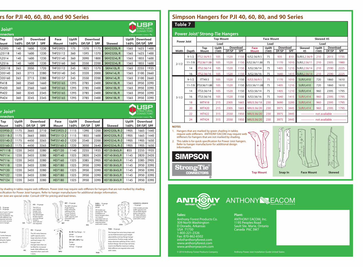
Simpson Hangers for PJI 40, 60, 80, and 90 Series
NOTES
1. Hangers that are marked by green shading in tables require web stiffeners. ANTHONY EACOM may require web stiffeners for hangers that are not marked by shading.
2. This table is for quick specification for Power Joist hangers. Refer to hanger manufacturer for additional design information.
SkewedFace MountSnap InTop Mount
USP Hangers for PJI 40, 60, 80, and 90 Series
LF – 18 gauge LT – 18 gauge
The LF and LT series feature fast and easy installation. No web stiffeners are required, and only one screw secures joist in hanger.
MIT – 16 gauge
The MIT’s Positive Angle Nailing helps eliminate splitting of the I-Joists’ bottom flange. Features uplift capacity and extended seat design
IUS – 18 gauge
The IUS is a new hybrid hanger that incorporates the advantages of face-mount and top-flange hangers. Joist nails are not required.
SUR/L – 16 gauge SURI/LI – 16 gauge
All models are skewed 45°. The installation of these hangers does not require a beveled end cut. Web stiffeners are required when used with I-Joists.
LSSUH310, LSSU410 – 16 gauge
LSSU models provide uplift capacity and can be field sloped and/or skewed to 45°. Web stiffeners are required when used with I-Joists.
LSSU
THAI – 18 gauge
This hanger has extra long straps and can be field-formed to give height adjustability and top-flange hanger convenience. Positive angle nailing helps eliminate splitting of the I-Joist’s bottom flange. Not all strap nail holes need to be filled for maximum nailing. Web stiffeners are required when used with I-Joists.
THAI
HU – 14 gauge
The HU series features uplift capacity and a large selection of sizes and load ranges. HU hangers have triangle holes that can be filled for increased loads. Web stiffeners are required when used with I-Joists.
HUWPU
W, WI: Top flange – 12 gauge Stirrup – 12 gauge
WP, WPI, WPU: Top flange – 7 gauge Stirrup – 12 gauge
MIU – 16 gauge
The MIU series features 16 gauge steel and extra nailing for higher loads than the IUT.
Plant:ANTHONY EACOM, Inc.1195 Peoples RoadSault Ste. Marie, OntarioCanada P6C 3W7
© 2014 Anthony Forest Products Company Anthony Power Joist Installation Guide United States
Sales:Anthony Forest Products Co.309 North WashingtonEl Dorado, Arkansas USA 717301-800-221-2326Fax: 870-862-6502info@anthonyforest.comwww.anthonyforest.comwww.anthonyeacom.com
Table 5Single Power Joist® USP Structural Connectors
Top Uplift Download Face Uplift Download Uplift Download Width Depth Mount 160% DF/SP SPF Mount 160% DF/SP SPF Skewed 160% DF/SP SPF
9-1/2 TFL2595 140 1600 1230 THF25925 175 1370 1175 SKH2520L/R 1565 1625 1400
2-1/2 11-7/8 TFL25118 140 1600 1230 THF25112 360 1595 1370 SKH2520L/R 1565 1625 1400
14 TFL2514 140 1600 1230 THF25140 360 2090 1800 SKH2524L/R 1565 1855 1600 16 TFL2516 140 1600 1230 THF25160 360 2550 2200 SKH2524L/R 1565 1855 1600 11-7/8 THO35118 265 2050 1720 THF35112 245 1825 1570 SKH410L/R 1565 2255 1935 14 THO35140 265 2715 2280 THF35140 245 2320 2000 SKH414L/R 1565 3100 2660 16 THO35160 265 2715 2280 THF35157 245 2550 2200 SKH414L/R 1565 3100 2660 3-1/2 18 TFI418 360 2560 1660 THF35165 1295 2785 2400 SKH418L/R 1565 3950 3390 20 TFI420 360 2560 1660 THF35165 1295 2785 2400 SKH418L/R 1565 3950 3390 22 TFI422 360 3245 2345 THF35165 1295 2785 2400 SKH418L/R 1565 3950 3390 24 TFI424 360 3245 2345 THF35165 1295 2785 2400 SKH418L/R 1565 3950 3390
NOTES1. Hangers that are marked by shading in tables require web stiffeners. Power Joist may require web stiffeners for hangers that are not marked by shading.2. This table is for quick specification for Power Joist hangers. Refer to hanger manufacturer for additional design information.3. Hangers for Double Power Joist are special order. Consult USP for pricing and lead times.
Table 6Double Power Joist® USP Structural Connectors
Top Uplift Download Face Uplift Download Uplift Download Width Depth Mount 160% DF/SP SPF Mount 160% DF/SP SPF Skewed 160% DF/SP SPF
9-1/2 THO25950-2 1175 3665 2710 THF25925-2 1115 1390 1200 SKH2520L/R-2 1905 1665 1440 5 11-7/8 THO25118-2 1175 3665 3005 THF25112-2 1115 1855 1600 SKH2520L/R-2 1905 1665 1440 14 THO25140-2 1175 4450 3265 THF25140-2 1220 2540 2200 SKH2524L/R-2 1905 1905 1650 16 THO25160-2 1175 4450 3265 THF25160-2 1220 3050 2640 SKH2524L/R-2 1905 1905 1650 11-7/8 BPH71118 1220 3455 3280 HD7120 1140 2255 1935 HD7120-SK45L/R3 855 2255 1935 14 BPH7114 1220 3455 3280 HD7140 1525 2820 2420 HD7140-SK45L/R3 1145 2820 2420 16 BPH7116 1220 3455 3280 HD7160 1525 3385 2905 HD7160-SK45L/R3 1145 3385 2905 7 18 BPH7118 1220 3455 3280 HD7180 1525 3950 3390 HD7180-SK45L/R3 1145 3950 3390 20 BPH7120 1220 3455 3280 HD7180 1525 3950 3390 HD7180-SK45L/R3 1145 3950 3390 22 BPH7122 1220 3455 3280 HD7180 1525 3950 3390 HD7180-SK45L/R3 1145 3950 3390 24 BPH7124 1220 3455 3280 HD7180 1525 3950 3390 HD7180-SK45L/R3 1145 3950 3390
Top Mount Face Mount Skewed 45
Table 23
Power Joist® Strong-Tie Hangers
Power Joist
Load Load Load
Top Uplift Download Face Uplift Download Skewed Uplift Download Width Depth Mount (160) DF/SP SPF Mount (160) DF/SP SPF 45 (160) DF/SP SPF
9-1/2 ITS2.56/9.5 105 1520 1150 IUS2.56/9.5 75 935 810 SUR/L2.56/9 210 2015 1735
2-1/2 11-7/8 ITS2.56/11.88 105 1520 1150 IUS2.56/11.88 75 1170 1010 SUR/L2.56/11 210 2305 1980
14 ITS2.56/14 105 1520 1150 IUS2.56/14 75 1405 1210 SUR/L2.56/14 210 2590 2225
16 ITS2.56/16 105 1520 1150 IUS2.56/16 75 1640 1415 SUR/L2.56/14 210 2590 2225
9-1/2 ITT49.5 105 1520 1150 IUS3.56/9.5 75 1170 1010 SUR/L410 720 1860 1610
11-7/8 ITS3.56/11.88 105 1520 1150 IUS3.56/11.88 75 1405 1210 SUR/L410 720 1860 1610
14 ITS3.56/14 105 1520 1150 IUS3.56/14 75 1405 1210 SUR/L414 960 2395 1795
3-1/2 16 ITS3.56/16 105 1520 1150 IUS3.56/16 75 1640 1415 SUR/L414 960 2395 1795
18 MIT418 215 2305 1665 MIU3.56/18 230 3690 3200 SUR/L414 960 2395 1795
20 MIT420 215 2305 1665 MIU3.56/20 230 3975 3445 SUR/L414 960 2395 1795
22 HIT422 315 2550 1950 MIU3.56/20 230 3975 3445 -------------- not available --------------
24 HIT424 315 2550 1950 MIU3.56/20 230 3975 3445 -------------- not available --------------
Table 7
IUSSUL
MIT