anti-collision light systems installation and …page 5 strobe system wiring page 6 strobe power...
TRANSCRIPT

ANTI-COLLISION LIGHT SYSTEMSINSTALLATION AND SERVICE MANUAL
JANUARY, 2007Approved under
STC SA6NESTC SA21NESTC SA615EASTC SA800EA
© 2007 Whelen Engineering Company, Inc. Document #05131A
ROUTE 145, CHESTER, CT 06412-0684PHONE: (860) 526-9504
FAX: (860) 526-2009www.whelen.com
®®
ENGINEERING COMPANY, INC.

2
WHELEN ENGINEERING COMPANY, INC.ROUTE 145, CHESTER, CT 06412-0684
PHONE: (860) 526-9504 ● FAX: (860) 526-2009
To view our products and contact us, visit Whelen at www.whelen.com or
we can be emailed at [email protected]
Table of ContentsPage 2 Table of Contents/Company InformationPage 3 Strobe System RequirementsPage 4 Aircraft Not Specifically Mentioned
on the Eligibility ListPage 5 Strobe System WiringPage 6 Strobe Power Supply InstallationPage 7-9 Strobe Power SuppliesPage 7 HDACFPage 8 A490ATSCPage 9 A490TCFPage 9 A490TCCFPage 10-13 Self Contained Light AssembliesPage 10, 11 70900 SeriesPage 12, 13 71055 SeriesPage 14, 15 HRCFA SeriesPage 14, 15 SACFA Series
Document #05131A
Page 16-26 Strobe Lighthead AssembliesPage 16-17 A470A SeriesPage 16-17 A450 Series, H102 & H103 SeriesPage 18-19 A650PG/PR SeriesPage 20 A610/A612 SeriesPage 21 A625 SeriesPage 22-23 A500A SeriesPage 24-25 A600 PG/PR SeriesPage 26 A650 SeriesPage 27 Strobe Power Supply Replacement Cross
Reference ListingPage 28 Continued Airworthiness Flow ChartPage 29-30 Strobe System TroubleshootingPage 31-32 Parts BreakdownPage 33-49 Appendix APage 50 Notes
Office: Jeff , Sharon, Fred, and Jessica Jim and Dennis, Whelen Corporate Pilots
Whelen Corporate Headquarters and Chester Airport
Whelen’s Corporate Jet
Computer Aided Design Engineering Testing and Quality Assurance Manufacturing Facilities
Making the Finest Aviation Lighting Products For all your Aviation Warning Lighting applications
Welcome to Whelen
Designed and Manufactured in the U.S.A.
Whelen manufacturers a full line of Warning Products
Police Fire
Tow E.M.T.
Sirens
D.O.T. Industrial

LEFTW
ING
TIP
STR
OBE
IFR
EQ
UIRED
THIRD TAIL STROBE
COV
ER
AG
E
RIGHTW
ING
TIP
STROBE
PositionGreen
110º
PositionRed
110º
TailPosition
White70º
TailPositionWhite70º
0º
180º
360º
-75º-30º -30º
75+ º30+ º 30+ º
VERTICAL FINOne anti-collision strobe lightmounted on the vertical fin willmeet the minimum require-ments on most aircraft. A halfred and half white lens is re-commended.
WINGTIPTwo wingtip strobe lights thatprotrude beyond the wingtip,their light converging in frontand back of the aircraft within1200 ft. is an approved anti-collision strobe light system.
ENCLOSED WINGTIPEnclosed wingtip anti-collisionstrobe lights, require a thirdstrobe light on the tail or verti-cal fin, to fill in the requiredlight envelope. This is anapproved anti-collision system.
FUSELAGEIn a fuselage mounted anti-collision strobe light system, aminimum of two strobe lightsare necessary to get therequired vertical coverage.This is an approved anti-colli-sion system.
An approved anti-collisionstrobe light system must proj-ect light 360° around the air-craft’s vertical axis. One ormore strobe lights can beused.
An approved anti-collisionstrobe light system must proj-ect light + or - 30° above andbelow the horizontal plane ofthe aircraft. One or morestrobe lights can be used. The+ or - 75° projected light isrequired since July 18, 1977.
Approved light pattern in the horizontal plane. The anti-collisionwingtip mounted lightsmust converge within1200 feet directly infront and rear of theaircraft on center line. If the wingtip strobe light convergence isgreater than 1200 ft. inback of the aircraft, a 3rd light is necessary.
LOCATIONS ON THE AIRCRAFT FORANTI-COLLISION STROBE LIGHTS, TO COMPLY
TO THE LIGHT PATTERN REQUIREMENTS.
POSITION LIGHTS AND ANTI-COLLISION LIGHTDISTRIBUTION PATTERNS REQUIREMENTSINTRODUCTION TO WHELEN ANTI-COLLISION STROBE LIGHTING
SYSTEMS, STC SA800EA/STC SA615EA/STC SA6NE/STC SA21NEWhelen’s Anti-Collision Strobe Light Systems are approved under STCSA615EA, STC SA800EA, STC SA6NE, and STC SA21NE, manufactured underPMA as an approved anti-collision light for all aircraft, when installation isaccomplished in accordance with the following instructions.Whelen’s Anti-Collision Strobe Light Systems are designed and approvedspecifically for General Aviation Aircraft, to comply to FAR 91.205(c) (3) (visu-al flight rule night) requirements.Whelen’s approved Anti-Collision Strobe Light Systems can be installed on allaircraft by completing the installation with reference to this Installation andService Manual, and the appropriate technical data listed below:ADVISORY CIRCULAR 43.13-1A, Chapter 11, Sections 1, 2, 3 and 7, Electrical Systems.ADVISORY CIRCULAR 43.13-2A, Chapters 1 and 2, Radio Installations.ADVISORY CIRCULAR 43.13-2A, Chapter 4, Anti-Collision Light Installations.ADVISORY CIRCULAR 20.21, 12-3-64, Application of Glass Fiber Laminates in Aircraft.
ANTI-COLLISION AND POSITION LIGHT REQUIREMENTS, LOCATIONS, & DISTRIBUTION PATTERNSAll aircraft must have an approved anti-collision light and position light systemfor nighttime operations. The position lights consist of an Aviation Red on theleft side, an Aviation Green on the right, and an Aviation White taillight (REF. FAR23.1389). The anti-collision lighting system is required under FAR PART 91.205(c)(3).There are different requirements affecting different aircraft. These aircraft arecategorized by the date of application for type certificate. Home built aircraft aredetermined by the date of issuance of the Experimental Operating Limitations.The different categories are as follows:Aircraft for which type certificate was applied for after April 1, 1957 toAugust 10, 1971:These anti-collision systems must produce a minimum of 100 effective candelain Aviation Red or White (REF. FAR 23.1397), 360º around the aircraft’s verticalaxis, 30º above and below the horizontal plane (REF. FAR 23.1401).Aircraft for which type certificate was applied for after August 11, 1971 toJuly 18, 1977:These anti-collision systems must produce a minimum of 400 effective candelain Aviation Red or White (REF. FAR 23.1397), 360º around the aircraft’s verticalaxis, 30º above and below the horizontal plane (REF. FAR 23.1401).Aircraft for which type certificate was applied for after July 18, 1977:These anti-collision systems must produce a minimum of 400 effective candelain Aviation Red or White (REF. FAR 23.1397), 360º around the aircraft’s verticalaxis, 75º above and below the horizontal plane (REF. FAR 23.1401).*The position lights must be wired independently of anti-collision lights.
GENERAL AVIATION MINIMUM POSITION LIGHTING REQUIREMENTSFor compliance to FAR Part 23.1385 through 23.1397, VFR flight rule nightrequirements on a General Aviation aircraft, you must have a TSO,d Aviation Redforward position light on the left and an Aviation Green forward position light onthe right. See Figure 7, page 4.These are normally mounted on the most outward extremity of the airframe sothey can project their light directly in front of the aircraft 0 degree to 110degrees left and right horizontally, and 180 degrees up and down vertically,unobstructed by any part of the aircraft.The tail position light must project its Aviation White light toward the rear of theaircraft, 70 degrees horizontally left and right from 0 degree straight backbehind the aircraft, 180 degrees up and down, 0.04 Steradian (131.36 sq.degrees) interference is allowable, reference FAR Part 23.1387(c). More thanone light is acceptable.
© 2007 Whelen Engineering Company, Inc. Document #05131A 3

ANTI-COLLISION LIGHT INSTALLATION PROCEDURES STC SA800EA / STC SA615EA / STC SA21NEThe following information is to assist in the installation of a customWhelen anti-collision strobe light system on any aircraft, and how toreturn the aircraft back to service with compliance to FAR Part91.205(c) (3).
1. Choose the anti-collision light system which is most applicable tothe aircraft.
2. With reference to the STC’s “Limitation and Conditions” for field ofcoverage requirements. Check the field of coverage of the pro-posed location.
3. These STC’s document that Whelen’s anti-collision strobe lightsmeet the requirements as specified in AC 43.13-2A, Chapter 4,PAR.51 (a and b) (1). STC SA615EA covers replacement of originalequipment, STC SA800EA and STC SA21NE cover installation ofnew anti-collision light systems.
4. Vertical fin mounted anti-collision strobe beacons will conform tothe FAR 23.1401, 0.5 steradian (1642 sq. degrees) maximum solidangle blockage requirements on most standard configurations(CAM 3 and FAR Part 23) high or low wing type aircraft. An aver-age solid angle blockage for an installation of this type is 1324 sq.degrees.
5. Fuselage mounted anti-collision light systems require two (2) anti-collision strobe beacons to get the +/– 75 degrees required. Twolights mounted in this manner exceed the steradian requirementsof 21,600 sq. degrees total coverage.
6. Fuselage mounted anti-collision lights should be located on thefuselage center line to reduce reflection on the wings as much aspossible. They should be mounted near the trailing edge of thewing, to reduce cockpit reflection.
APPROVED METHOD OF DETERMINING ADEQUATE COVERAGE OF WING AND TAIL STROBE LIGHT INSTALLATIONSThe most practical system is the approved wingtip anti-collision strobelight system. These systems consist of two or more lights to completethe anti-collision light requirement. There is no question as to theircomplying to the field of coverage when the installation is completed(Reference to the following instructions).The acceptable distance for the two wingtip anti-collision strobe lightsto converge in front and back of the aircraft on center line is 1200 feet.If both wingtip anti-collision strobe lights can be seen at 1200 feet orless directly in front and back of the aircraft, it is considered a point oflight source, therefore a third light is not necessary.The wingtip anti-collision light must be located in such a way that it willproject light +/– 75 degrees above and below the horizontal axis of theaircraft, and the summation of the 2 or 3 lights will project light 360degrees around the vertical axis.PILOT AND CREW INTERFERENCE: In some installations it will be nec-essary to mask the strobe lighthead assembly to reduce pilot annoy-ance. This interference problem varies from one aircraft to another ofthe same model, due to paint schemes and colors. The NavigationLight Detector will be a source of reflection and should be reduced insize, or masked as necessary. A small aluminum or plastic platemounted between the navigation light and the wingtip protruding up ordown as required (like some plastic navigation light detectors, andtrimmed to shadow the objectionable reflected area) is simple and veryeffective.The solid angle blockage must be reviewed after installing any maskingthat will disturb the 360 degrees by +/– 75 degrees pattern. The afore-mentioned type masking used on wingtip lighting seldom interfereswith this pattern.
ESTABLISHING SOLID ANGLE BLOCKAGE WITH REFERENCE TO AC43.13-2A, CHAPTER 4.
1. To determine the vertical angles to use with reference to Figure 7and 8 of the aforementioned chapter 4, attach a long string to thesubject light source location.
2. Fix a navigational-type plotter or protractor to the string withweighted thread fixed to the center of the scale for a plumb bob.
3. Level the aircraft or determine the offset angle.4. Pull the string over the point of solid angle blockage (Ref. Fig. 6
page 4). Any angles greater than +/– 75 degrees vertical are not afactor.
5. Apply the vertical and horizontal angles to the graph paper (Ref.Fig. 4.8 and instructions in text of paragraph b6 & c of Chapter 4).
A flight test will be performed by properly certified pilot with referenceto paragraph 52(a) (b) of Chapter 4.
COMPLETING THE ANTI-COLLISION LIGHT INSTALLATION1. Check all avionics systems for interference from this installation,
reference AC 43.13-2A, Chapter 4, Paragraph 52(b).2. A flight check will be performed by a properly certificated pilot with
reference to AC 43.13-2A, Paragraph 52(a) and (b).3. If a solid angle blockage document must be established, it should
be performed after all masking has been installed and all flight test-ing is completed. See page 3 of this manual.
4. WATERPROOFING OF STROBE LIGHT INSTALLATIONS: Whennecessary to waterproof the installation of a strobe light mountingto the aircraft, apply GE (silicone rubber) RTV 102 (or equivalent)around the open area where water could get in.
5. Label all switches and breakers, install Pilot Warning Placard.6. Up-date aircraft records and complete form 337.
4 Document #05131A
AIRCRAFT NOT SPECIFICALLY MENTIONED ON THE ELIGIBILITY LIST

Interconnecting Cable1. The Whelen interconnecting cable shall be secured in place with
approved aviation techniques.2. The cable shall not parallel ADF, Gyro or Flux Gate compass
leads closer than 12 inches.3. Reference should be made to AC 43.13-1B, Chapter 11, Sections
3 and 7, when routing and fishing the interconnecting cable.4. Leave a service loop at the strobe lighthead end, to allow access
to the connector for flash tube replacement without having to dis-assemble the aircraft.
5. CABLE COLORING CODE:PIN 1 RED - (Anode)PIN 2 BLACK - (Cathode, flash tube ground)PIN 3 WHITE - (Trigger)SHIELD - Ground at the power supply end only
Caution: When pins 1 and 2, or pins 2 and 3 are reversed, the systemwill appear to operate normally, however this condition will cause pre-mature flash tube failure.
Observe Color and Pin NumbersThe retaining clip on the side of each pin or socket of the A441 andA442 connector assemblies must be bent out (Reference illustration,Figure 5A shown above) so that they positively snap into the AMP 3position socket nylon connector housing.If it is not possible to get a good grip, it is recommended that the pinsand sockets be soldered to prevent burning of the wires.
Intermixing Strobe Light System EquipmentObserve Color and Pin NumbersCables Connecting Strobe Lights MUST BE ConnectedCorrectly!Whelen Engineering and Aero-flash wiring between light assembliesand remote power supplies are identical as pictured below in Figure 5B.
Grimes and SDI (Hoskins) wiring between light assemblies and remotepower supplies are identical as pictured below in Figure 5C.
Both Grimes and SDI sometimes use MS (Cannon Type) connectors:
Position A = RED (Anode), Position B = White or Blue(Trigger), Position C = (Cathode) Black or Yellow
INSTALLATION CABLE KITSAll Kits include required connectors for hooking up the strobe light to the power supply only, warning placards and the Installation Service Manual. Cable is 16 gauge 3/c shielded. The cable diameter is .275”. The weight is .050 lbs. per linear foot. Kits do not include switches or breakers. In order to maintain the integrity of the installation, one of the following installation kits must be used. If the installer chooses to use different cable, it must have the same or better electrical characteristics.
Model Number Part Number DescriptionHS5 . . . . . . . . . . . .01-0750215-00 . . . . .5’ Cable KitHT10 . . . . . . . . . . . .01-0750218-00 . . . . .10’ Cable KitHS30 . . . . . . . . . . .01-0750214-00 . . . . .30’ Cable KitHD60 . . . . . . . . . . .01-0750206-00 . . . . .60’ Cable KitHDT390 . . . . . . . . .01-0750205-00 . . . . .90’ Cable KitHT . . . . . . . . . . . . .01-0750216-00 . . . . .Install Kit Only No Cable
REPLACEMENT CONNECTORSModel Number Part Number DescriptionA441 . . . . . . . . . . . .01-0430011-00 . . . . .3 Position Male Connector with PinsA442 . . . . . . . . . . . .01-0410823-00 . . . . .3 Position Female Connector with SocketsA444 . . . . . . . . . . . .02-0230007-00 . . . . .2 Position Male Connector with PinsA446 . . . . . . . . . . . .02-0230085-00 . . . . .2 Position Female Connector with Sockets
A441
A442
A446
A444
C L I P
S H I E L D
W H I TE
B L A C K
R E D
C L I P
S H I E L D
B L A C K
W H I T E
R E D
C L I P
S H I E L D *
W H I TE
B L A C K
R E D
STROBE SYSTEM WIRING
A441 PINS POWER SUPPLY ENDA442 SOCKETS FLASH TUBE END
© 2007 Whelen Engineering Company, Inc. Document #05131A 5
Figure 5A
Figure 5B
Figure 5C

INSTALLATION PROCEDURES:
Location1. Consider areas or locations designated by the aircraft man-
ufacturer. Do not mount the strobe power supply closer thanthree (3) feet of the ADF loop.
2. For alternate locations, consider areas such as the cabinbaggage compartment, the floor under the seat, nonstruc-tural bulkheads, firewalls, etc.
3. If necessary, fabricate support brackets or shelves, andattach them to the aircraft structure to provide a mountingsurface that will withstand the inertia forces stipulated inchapters 1 & 3 of AC 43.13-2A.
4. An “IA” or other representative of the FAA must approvedocumentation of structural integrity of the fabricated instal-lation.
5. When installing the strobe light power supply in an invertedposition, drill a 3/16” diameter hole in the lowest corner ofthe cover to provide for moisture drainage. Care must betaken not to let the drill protrude into the power supply, forit will inflict damage to the electronic components.
6. Specifically call out the location of the strobe light powersupply on FAA form 337.
Wiring
WARNING!!! STROBE LIGHT POWER SUPPLIES AREPOLARITY SENSITIVE. REVERSING THE INPUTPOLARITY WILL CAUSE SEVERE DAMAGE TO THEPOWER SUPPLY!
Steps below: Ref. AC 43.13-1B, Chapter 11, Sections 1, 2, 3 & 7.1. Choosing wire size of A+ input lead, refer to Paragraph 444
“Electric Wire Chart” Figure 11.7 & 11.7A, with reference to“Strobe Light Model Current” requirement chart on page 6 &11, and “Wire and Circuit Protection Chart” Figure 11.1.
2. Shielded wire is not generally necessary, but has proveneffective in reducing the possibility of radio interference.
3. The power supply shall acquire its power from a low imped-ance source such as the alternator or generator end of theelectrical buss as close to the battery as possible. Do notground power supply to airframe. This can attenuate emi/rfinoise to airframe causing it to act as an antennae for inter-ference in aircraft audio & electrical systems.
4. For penetrating pressure hull, refer to the aircraft servicemanual.
5. Check all avionics systems for interference.
Important Note:Your new strobe power supply has an additional circuit built-into prevent self-ionization (steady glowing) of the strobe tubes.In some cases, when replacing older power supplies, the bareshield wire in the existing harness is pinned together at eachend with the black wire. The following modification must bemade to ensure proper operation.1. At the strobe tube end of the cable, cut the shield wire and
tape it off (DO NOT CUT THE BLACK WIRE).2. At the power supply end of the cable, cut the shield wire and
connect it to a good ground (DO NOT CUT THE BLACK WIRE).
3. This must be done for each strobe light connection (SeeFigure 6A).
PIN 1 = RED (ANODE)PIN 2 = BLACK (CATHODE)PIN 3 = WHITE (TRIGGER)SHIELD = RFI DRAIN TO GROUND
POWERSUPPLYEND
123
X
3 POS. PIN HSG3 CONDUCTOR SHIELDED CABLE
SHIELD WIRE CUT AND TAPE SHIELD WIREAT STROBE TUBE END
GROUND SHIELD WIREAT POWER SUPPLY END ONLY
3 POS. SOCKET HSG
STROBETUBEEND
123
Figure 6A
STROBE POWER SUPPLY INSTALLATION
6 Document #05131A

OperationThis power supply will operate up to 3 strobe lighthead assemblies.When operating two lights in the alternating mode, 42 joules of powerare produced for each light. While in simultaneous mode, power toeach light is 21 joules. When operating 3 lights, strobe outlet 1 pro-duces 42 joules of power and alternates with strobe outlets 2 & 3 (pro-ducing 21 joules each) that flash simultaneously (see Figure 7B).
Trigger FunctionJumping pins 1 and 2 on the trigger plug will provide an alternatingflash pattern between strobe outlet 1 and strobe outlet(s) 2 and/or 3.Installing a switch in series with the jumper will allow strobe outlets 2& 3 to be turned off, while strobe outlet 1 remains on (see Figure 7B).
Dimensions
Mounting
MODEL HDACF STROBE POWER SUPPLY ASSEMBLYFAA/PMA APPROVEDSpecificationsModel Number . . . . . HDACFPart Number . . . . . . . 01-0770028-05Current Draw . . . . . . 7.0 Amps @ 14 Volts D.C.
3.5 Amps @ 28 Volts D.C.Weight . . . . . . . . . . . 2.1 lbs.Length . . . . . . . . . . . 5.50”Height. . . . . . . . . . . . 2.37”
5.03
5.406.56
PIN #3 N/C
18G WIRES
2.37 (MAX)RED (+14/28V)
BLACK (-) GROUND
.187 DIA. (4 PLACES)
PIN #1 = (+) 14/28V
PIN #2 = (-) GROUND
PIN #3 = N/CPIN #2 = CATHODEPIN #3 = TRIGGER
PIN #1 = ANODE
POWER INPUT: TRIGGERSELECTION:
STROBE OUTPUTS:
1 2 3
ALT
SYNC
STROBE OUTLETS
TRIGGER
SELECTOR
OUTLET
POWER
IN#1#2
14V or 28V
-
+
OFF
ON
Switch normally closed1/10 amp rated
Jumper inserted intotrigger selector outlet
SYNC
ALT
#3
32
1
(1) +
Jumper to be insertedin trigger selector outlet
Outlet1
Outlet2
Outlet3
Connector forinput power cable
STROBE HOOK-UP- RED - ANODE- BLACK - CATHODE- WHITE - TRIGGER
PIN 1PIN 2PIN 3
1 TYP.
2 TYP.
3 TYP.
(2) -
(3)N/C
STROBE OUTLETS
PIN
© 2007 Whelen Engineering Company, Inc. Document #05131A 7
Figure 7A
Figure 7B
Figure 7D
Figure 7C
2.50”
6.00”
Suggested Mounting Plan
.203” DIA. (4) PLACES

.938”MTG.
1.600”MTG.
5.675 MTG.
5.562 MTG.
.187 DIA.(8) MOUNTING HOLES
OperationThis power supply will operate ONE strobe lighthead assembly at 34joules of power. It is equipped to flash up to five (5) other like unitssimultaneously when an 18 gauge wire is connected to outlet 3 on theinput power connector.
Looking at the power supply connectors with the mounting plate flat ona bench, the left connector is the strobe outlet. The right connector isthe power input and synchronization.Left Connector (Power Output)Pin 1. (Top) - RED wire/anodePin 2. (Center) - BLACK wire/cathodePin 3. (Bottom) - WHITE wire/triggerRight Connector (Power Input)Pin 1. (Top) - RED wire/13 to 30 volt, positive inputPin 2. (Center) - BLACK wire/groundPin 3. (Bottom) - Synchronization pin/If synchronization is desired,
connect an 18 gauge wire between pin 3 on each power supply.
Dimensions
8
MODEL A490ATSCSTROBE POWER SUPPLYFAA/PMA APPROVEDSpecificationsModel Number . . . . . A490ATSCPart Number . . . . . . . 01-0770062-03Position Lights -Current Draw . . . . . . 4.0 Amps @ 14 Volts D.C.
2.0 Amps @ 28 Volts D.C.Weight . . . . . . . . . . . 1.7 lbs.Length . . . . . . . . . . . 5.00”Width . . . . . . . . . . . . 3.12”Height. . . . . . . . . . . . 3.06”
OUTPUT POWER
POS. 1 (+), RED
POS. 2 (-), BLACK
POS. 3 - SYNC
1 - Anode2 - Cathode3 - Trigger
1 - (+)2 - (-)3 - SYNC
1
2
3
1
2
3
CHESTER, CONNECTICUT 06412-0684WHELEN ENGINEERING COMPANY
3.14”
6.25”
3.12”
5.00”
.95”
.65”
.080”
(1) ANODE(2) CATHODE(3) TRIGGER (3) SYNC
(2) -(1) +
POWEROUTPUT
Mounting
Figure 8B
Figure 8A
Figure 8C
Document #05131A

OperationMODEL A490TCF: This model operates one strobe lighthead. It is our most compact unit and can be mounted in the wingtip and/or the tail
adjacent to the lighthead. It produces an accumulated 19 joules of power.
It will only meet 400 ECP when used with the A470A-W. This unit can not be synchronized.
This power supply operates from 10 to 30 volts DC.
(Not approved for use with red strobe light).
OperationMODEL A490TCCF SERIES: This model is the same as the A490TCF but has a mounting plate with additional holes that directly replaces factory installed systems on single engine Cessna’s, Aero Commanders and Grumman Americans.
MODEL A490TCF STROBE POWER SUPPLYFAA/PMA APPROVEDModel Number . . . . . A490TCFPart Number . . . . . . . 01-0770006-08
MODEL A490TCCF STROBE POWER SUPPLYFAA/PMA APPROVEDModel Number . . . . . A490TCCFPart Number . . . . . . . 01-0770006-09
Specifications (Both Models)Current Draw . . . . . . 1.7 Amps @ 14 Volts D.C.
0.85 Amps @ 28 Volts D.C.Weight . . . . . . . . . . . 1.2 lbs.Length . . . . . . . . . . . 5.00”Width . . . . . . . . . . . . 3.12”Height. . . . . . . . . . . . 2.38”
© 2007 Whelen Engineering Company, Inc. Document #05131A 9
SUGGESTED MOUNTING PLANSTANDARD
3.12
2.38
5.00
6.18.080
20.00" 2.00" INPUT CABLEWHITE +14/28VBLACK (-) GROUND
±
LC
LC
LC
20.00" 2.00" OUTPUT CABLE±
5.562”
.938”
.191 DIA.(4) PLACES
MOUNTING HOLES .191 DIA. (4) PLACES
SUGGESTED MOUNTING PLAN FOR OPTIONAL BASE
6.180”
3.750”
MOUNTING HOLES.187” DIA. (4) PLACES
LC
LC
A490TC UNITSPLATE BOTTOM VIEW
OUTPUTCABLE
INPUT CABLE
.187” DIA. (4) PLACES
3.250
5.000
RED
BLACK
WHITE
(ANODE) POSITION 1(CATHODE) POSITION 2(TRIGGER) POSITION 3
WHITE (+14/28 VDC)BLACK (GROUND)
RED
BLACK
WHITE
(ANODE) POSITION 1(CATHODE) POSITION 2(TRIGGER) POSITION 3
WHITE (+14/28 VDC)BLACK (GROUND)
Dimensions
Mounting
Dimensions
Mounting
Figure 9A
Figure 9B
Figure 9C
Figure 9D
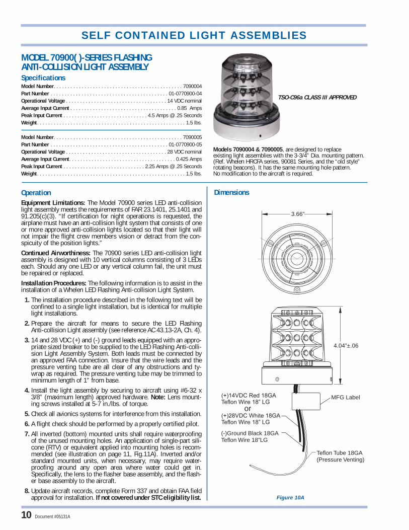
MODEL 70900( )-SERIES FLASHING ANTI-COLLISION LIGHT ASSEMBLYSpecifications Model Number. . . . . . . . . . . . . . . . . . . . . . . . . . . . . . . . . . . . . . . . . . . . . . 7090004Part Number . . . . . . . . . . . . . . . . . . . . . . . . . . . . . . . . . . . . . . . . . . 01-0770900-04Operational Voltage . . . . . . . . . . . . . . . . . . . . . . . . . . . . . . . . . . . . 14 VDC nominalAverage Input Current . . . . . . . . . . . . . . . . . . . . . . . . . . . . . . . . . . . . . . 0.85 AmpsPeak Input Current . . . . . . . . . . . . . . . . . . . . . . . . . . . . . . 4.5 Amps @ .25 SecondsWeight . . . . . . . . . . . . . . . . . . . . . . . . . . . . . . . . . . . . . . . . . . . . . . . . . . . . . 1.5 lbs.
Model Number. . . . . . . . . . . . . . . . . . . . . . . . . . . . . . . . . . . . . . . . . . . . . . 7090005Part Number . . . . . . . . . . . . . . . . . . . . . . . . . . . . . . . . . . . . . . . . . . 01-0770900-05Operational Voltage . . . . . . . . . . . . . . . . . . . . . . . . . . . . . . . . . . . . 28 VDC nominalAverage Input Current. . . . . . . . . . . . . . . . . . . . . . . . . . . . . . . . . . . . . . 0.425 AmpsPeak Input Current . . . . . . . . . . . . . . . . . . . . . . . . . . . . . 2.25 Amps @ .25 SecondsWeight . . . . . . . . . . . . . . . . . . . . . . . . . . . . . . . . . . . . . . . . . . . . . . . . . . . . . 1.5 lbs.
or(+)28VDC White 18GATeflon Wire 18” LG
(+)14VDC Red 18GATeflon Wire 18” LG
4.04”±.06
3.66”
Teflon Tube 18GA(Pressure Venting)
(-)Ground Black 18GATeflon Wire 18”LG
MFG Label
TSO-C96a CLASS III APPROVED
OperationEquipment Limitations: The Model 70900 series LED anti-collisionlight assembly meets the requirements of FAR 23.1401, 25.1401 and91.205(c)(3). “If certification for night operations is requested, theairplane must have an anti-collision light system that consists of oneor more approved anti-collision lights located so that their light willnot impair the flight crew members vision or detract from the con-spicuity of the position lights.”Continued Airworthiness: The 70900 series LED anti-collision lightassembly is designed with 10 vertical columns consisting of 3 LEDseach. Should any one LED or any vertical column fail, the unit mustbe repaired or replaced.Installation Procedures: The following information is to assist in theinstallation of a Whelen LED Flashing Anti-collision Light System.
1. The installation procedure described in the following text will beconfined to a single light installation, but is identical for multiplelight installations.
2. Prepare the aircraft for means to secure the LED FlashingAnti-collision Light assembly (see reference AC 43.13-2A, Ch. 4).
3. 14 and 28 VDC (+) and (-) ground leads equipped with an appro-priate sized breaker to be supplied to the LED Flashing Anti-colli-sion Light Assembly System. Both leads must be connected byan approved FAA connection. Insure that the wire leads and thepressure venting tube are all clear of any obstructions and ty-wrap as required. The pressure venting tube may be trimmed tominimum length of 1” from base.
4. Install the light assembly by securing to aircraft using #6-32 x3/8” (maximum length) approved hardware. Note: Lens mount-ing screws installed at 5-7 in./lbs. of torque.
5. Check all avionics systems for interference from this installation.6. A flight check should be performed by a properly certified pilot.7. All inverted (bottom) mounted units shall require waterproofing
of the unused mounting holes. An application of single-part sili-cone (RTV) or equivalent applied into mounting holes is recom-mended (see illustration on page 11, Fig.11A). Inverted and/orstandard mounted units, when necessary, may require water-proofing around any open area where water could get in.Specifically, the lens to the flasher base assembly, and the flash-er base assembly to the aircraft.
8. Update aircraft records, complete Form 337 and obtain FAA fieldapproval for installation. If not covered under STC eligibility list.
Dimensions
10
Models 7090004 & 7090005, are designed to replace existing light assemblies with the 3-3/4” Dia. mounting pattern. (Ref. Whelen HRCFA series, 90081 Series, and the “old style” rotating beacons). It has the same mounting hole pattern. No modification to the aircraft is required.
Figure 10A
SELF CONTAINED LIGHT ASSEMBLIES
Document #05131A

LensP/N: 68-4990257-30
ScrewP/N: 14-062216-05M
GasketP/N: 38-0250843-00
Typical Mounting Hole Pattern
(3) #6-32 x 3/8Thread
1.00” Clearance for wires
LED ModuleP/N (14V): 01-0270918-01P/N (28V): 01-0270918-03
“RTV” required after hardware installationfor inverted (bottom) mounted units
115°
115°
© 2007 Whelen Engineering Company, Inc. Document #05131A 11
Figure 11B
Figure 11A
Model 70900 series LED installation

12Figure 12A
SELF CONTAINED LIGHT ASSEMBLIES
Document #05131A
MODEL 71055 SERIES ANTI-COLLISION LIGHT ASSEMBLYSpecifications Model Number. . . . . . . . . . . . . . . . . . . . . . . . . . . . . . . . . . . . . . . . . . . . . . 7105500Part Number . . . . . . . . . . . . . . . . . . . . . . . . . . . . . . . . . . . . . . . . . . 01-0771055-00Operational Voltage. . . . . . . . . . . . . . . . . . . . . . . . . . . . . . . . . . . . . . . . . . . 14 VDCAverage Input Current . . . . . . . . . . . . . . . . . . . . . . . . . . . . . . . . . . . . . . . 1.2 AmpsPeak Input Current. . . . . . . . . . . . . . . . . . . . . . . . . . . . . . . 6 Amps @ 0.25 SecondsWeight . . . . . . . . . . . . . . . . . . . . . . . . . . . . . . . . . . . . . . . . . . . . . . . . . . . . 0.55 lbs.
Model Number. . . . . . . . . . . . . . . . . . . . . . . . . . . . . . . . . . . . . . . . . . . . . . 7105501Part Number . . . . . . . . . . . . . . . . . . . . . . . . . . . . . . . . . . . . . . . . . . 01-0771055-01Operational Voltage. . . . . . . . . . . . . . . . . . . . . . . . . . . . . . . . . . . . . . . . . . . 28 VDCAverage Input Current. . . . . . . . . . . . . . . . . . . . . . . . . . . . . . . . . . . . . . . . 0.6 AmpsPeak Input Current. . . . . . . . . . . . . . . . . . . . . . . . . . . . . . . 3 Amps @ 0.25 SecondsWeight . . . . . . . . . . . . . . . . . . . . . . . . . . . . . . . . . . . . . . . . . . . . . . . . . . . . 0.52 lbs.
Adapter Plate
MFG. Label
(+)14VDC Red 18 Ga. or
TEFLON WIRE 12"±1”LG(+)28VDC White 18 Ga.
(-)GROUND Black 18Ga.Teflon Wire 12"±1"LG
2-19/32”(66mm)
3-3/32”(79mm)
OperationEquipment Limitations: The Model 71055 Series LED anti-collisionlight assembly meets or exceeds the requirements of FAR 23.1401,and FAR 91.205(c)(3).Continued Airworthiness: The 71055 Series LED anti-collision lightassembly is designed with 6 vertical columns consisting of 2 LED’seach. Should any one LED or any vertical column fail, the unit mustbe repaired or replaced. Periodically inspect the lens and replace ifthere is excessive scratching, discoloration or cracking.Installation Procedures: The Model 71055 is a self contained flash-ing beacon that requires no external flasher or power supply. In someinstallations, it may be necessary to remove several existing compo-nents. When replacing flashing halogen beacon assemblies, theflasher box and ballast resistor (if present), and associated wiring,need to be removed. When replacing strobe light assemblies, thestrobe power supply must be removed. In both cases, 18 gage DCvoltage wires, A+ & Ground (-), must be continued from the locationof the previous box, (flasher or power supply), to the location of thenew LED beacon.The following information is to assist in the installation of a WhelenLED Flashing Anti-collision Light System.1. The installation procedure described in the following text will beconfined to a single light installation, but is identical for multiple lightinstallations.2. Using the “suggested mounting hole pattern” prepare the aircraftfor means to secure the LED Flashing Anti-collision Light assembly.Remove any existing mounting adapters.3. 14 / 28 VDC (+) and (-) ground leads equipped with an appropri-ate sized breaker to be supplied to the LED Flashing Anti-collisionLight Assembly System. Both leads must be connected by anapproved FAA connection. Insure that the wire leads and the pressureventing tube are all clear of any obstructions and ty-wrap as required.4. Install the light assembly by first removing the lens. Remove theadapter plate. Attach the adapter plate to the aircraft mounting holes.Refer to page 2. Reinstall the light assembly and lens.5. Check all avionics systems for interference from this installation.6. A flight check should be performed by a properly certified pilot.7. All inverted (bottom) mounted units shall require waterproofing ofthe flasher base assembly to the aircraft. Note: Drill a 1/8” hole in thecenter of the lens for bottom mount units.8. Update aircraft records, complete Form 337 and obtain FAA fieldapproval for installation. If not covered under STC eligibility list.
Dimensions
TSO-C96a CLASS III APPROVED: The conditions andtests required for TSO approval of this article are mini-mum performance standards. It is the responsibility ofthose installing this article either on or within a specifictype or class of aircraft to determine that the aircraftinstallation conditions are within the TSO standards. TSOarticles must have separate approval for installation inaircraft. The article may be installed only if performedunder 14 CFR part 43 or the applicable airworthinessrequirements.
TSO-C96a CLASS III APPROVED
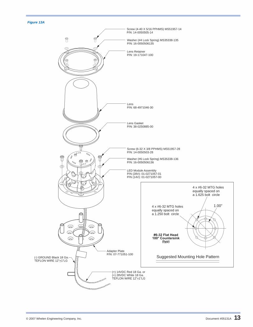
© 2007 Whelen Engineering Company, Inc. Document #05131A 13
Suggested Mounting Hole Pattern
Screw (4-40 X 5/16 PPHMS)P/N:
MS51957-1414-0050505-14
Washer (#4 Lock Spring) MS35338-135P/N: 16-0050506135
Washer (#6 Lock Spring) MS35338-136P/N: 16-0050506136
Screw (6-32 X 3/8 PPHMS) MS51957-28P/N: 14-0050503-28
Adapter PlateP/N: 07-771051-100
LED Module AssemblyP/N : 01-0271057-01P/N 14 : 01-0271057-00
(28V)( V)
Lens RetainerP/N: 19-171047-100
LensP/N: 68-4971046-30
4 x #6-32 MTG holesequally spaced ona 1.625 bolt circle
4 x #6-32 MTG holesequally spaced ona 1.250 bolt circle
#6-32 Flat Head100° Countersink
(typ)
1.00”
Lens GasketP/N: 38-0250885-00
(+) 14VDC Red 18 Ga. or
TEFLON WIRE 12” 1”LG+(+) 28VDC White 18 Ga.
(-) GROUND Black 18 Ga.TEFLON WIRE 12” 1”LG+
Figure 13A
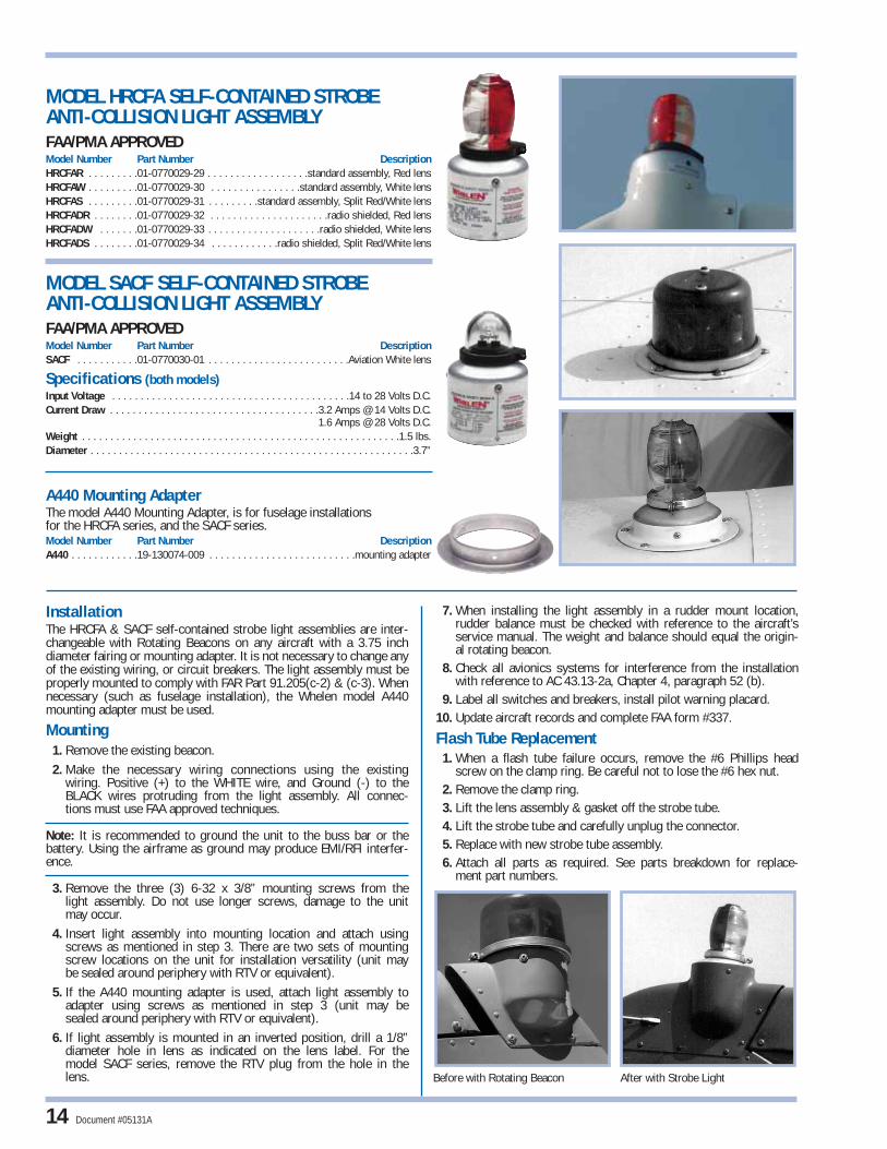
InstallationThe HRCFA & SACF self-contained strobe light assemblies are inter-changeable with Rotating Beacons on any aircraft with a 3.75 inchdiameter fairing or mounting adapter. It is not necessary to change anyof the existing wiring, or circuit breakers. The light assembly must beproperly mounted to comply with FAR Part 91.205(c-2) & (c-3). Whennecessary (such as fuselage installation), the Whelen model A440mounting adapter must be used.
Mounting1. Remove the existing beacon.2. Make the necessary wiring connections using the existing
wiring. Positive (+) to the WHITE wire, and Ground (-) to theBLACK wires protruding from the light assembly. All connec-tions must use FAA approved techniques.
Note: It is recommended to ground the unit to the buss bar or thebattery. Using the airframe as ground may produce EMI/RFI interfer-ence.
3. Remove the three (3) 6-32 x 3/8” mounting screws from thelight assembly. Do not use longer screws, damage to the unitmay occur.
4. Insert light assembly into mounting location and attach usingscrews as mentioned in step 3. There are two sets of mountingscrew locations on the unit for installation versatility (unit maybe sealed around periphery with RTV or equivalent).
5. If the A440 mounting adapter is used, attach light assembly to adapter using screws as mentioned in step 3 (unit may besealed around periphery with RTV or equivalent).
6. If light assembly is mounted in an inverted position, drill a 1/8”diameter hole in lens as indicated on the lens label. For themodel SACF series, remove the RTV plug from the hole in thelens.
7. When installing the light assembly in a rudder mount location,rudder balance must be checked with reference to the aircraft’sservice manual. The weight and balance should equal the origin-al rotating beacon.
8. Check all avionics systems for interference from the installationwith reference to AC 43.13-2a, Chapter 4, paragraph 52 (b).
9. Label all switches and breakers, install pilot warning placard.10. Update aircraft records and complete FAA form #337.
Flash Tube Replacement1. When a flash tube failure occurs, remove the #6 Phillips head
screw on the clamp ring. Be careful not to lose the #6 hex nut.2. Remove the clamp ring.3. Lift the lens assembly & gasket off the strobe tube.4. Lift the strobe tube and carefully unplug the connector.5. Replace with new strobe tube assembly.6. Attach all parts as required. See parts breakdown for replace-
ment part numbers.
MODEL HRCFA SELF-CONTAINED STROBE ANTI-COLLISION LIGHT ASSEMBLYFAA/PMA APPROVEDModel Number Part Number DescriptionHRCFAR . . . . . . . . .01-0770029-29 . . . . . . . . . . . . . . . . . .standard assembly, Red lensHRCFAW . . . . . . . . .01-0770029-30 . . . . . . . . . . . . . . . .standard assembly, White lensHRCFAS . . . . . . . . .01-0770029-31 . . . . . . . . .standard assembly, Split Red/White lensHRCFADR . . . . . . . .01-0770029-32 . . . . . . . . . . . . . . . . . . . . .radio shielded, Red lensHRCFADW . . . . . . .01-0770029-33 . . . . . . . . . . . . . . . . . . . .radio shielded, White lensHRCFADS . . . . . . . .01-0770029-34 . . . . . . . . . . . .radio shielded, Split Red/White lens
MODEL SACF SELF-CONTAINED STROBEANTI-COLLISION LIGHT ASSEMBLYFAA/PMA APPROVEDModel Number Part Number DescriptionSACF . . . . . . . . . . .01-0770030-01 . . . . . . . . . . . . . . . . . . . . . . . . .Aviation White lens
Specifications (both models)Input Voltage . . . . . . . . . . . . . . . . . . . . . . . . . . . . . . . . . . . . . . . . . .14 to 28 Volts D.C.Current Draw . . . . . . . . . . . . . . . . . . . . . . . . . . . . . . . . . . . . .3.2 Amps @ 14 Volts D.C.
1.6 Amps @ 28 Volts D.C.Weight . . . . . . . . . . . . . . . . . . . . . . . . . . . . . . . . . . . . . . . . . . . . . . . . . . . . . . . .1.5 lbs.Diameter . . . . . . . . . . . . . . . . . . . . . . . . . . . . . . . . . . . . . . . . . . . . . . . . . . . . . . . . .3.7”
A440 Mounting AdapterThe model A440 Mounting Adapter, is for fuselage installations for the HRCFA series, and the SACF series.Model Number Part Number DescriptionA440 . . . . . . . . . . . .19-130074-009 . . . . . . . . . . . . . . . . . . . . . . . . . .mounting adapter
Before with Rotating Beacon After with Strobe Light
14 Document #05131A
© 2007 Whelen Engineering Company, Inc. Document #05131A 15
#6-32 X 5/16 SS HEX NUT (MS35649-264)
16
38-0250429-00 RFI GASKET
4
5
6
7
15
68-2170504R50
68-2170504R30
68-2170504R60
LENS, A402ADR
LENS, A402ADW
LENS, A402ADS
#6-32x1/2 PPHMS(MS51957-30)
#6 INT. TOOTH LW(MS35333-71)
19-130074-100 A440 MOUNTING FLANGE (OPTIONAL)
2
3
8
10
13
11
9
14
12
68-2170504-30
68-2170504-60
01-0450685-00
38-0230840-00
01-0770619-00
N/A
N/A
N/A
N/A
01-0770044-02
LENS, A402AW
LENS, A402AS
CLAMP RING
GASKET
POWER SUPPLY ASSEMBLY
#6-32x3/8 PPHMS(MS51957-28)
A469B FLASH TUBE ASSY.
1 68-2170504-50 LENS, A402AR
ITEM DESCRIPTIONPART NUMBER
4
5
6
7
02-0350053-00
01-0770619-00
SA406 FLASH TUBE ASSEMBLY
#6-32 x 3/8 PPHMS (MS51957-28)
#6-32 x 5/16 SS HEX NUT (MS35649-264)
POWER SUPPLY HR-CF 14/28V
2
3
8
10
9
01-0450685-00
38-0230946-00
19-130074-100
N/A
N/A
N/A
N/A
CLAMP RING
GASKET
A440 MOUNTING FLANGE (OPTIONAL)
#6 INT TOOTH L/W (MS 35333-71)
#6-32 x 1/2 PPHMS (MS51957-30)
1 68-4230044-30 SA402 LENS (CLEAR)
ITEM DESCRIPTIONPART NUMBER
EL
OH8/1
LLIR
D
DE
TREVNI
FI
FRONT
5.00” DIA 4.65” DIA. B.C.
.156” DIA.(5) HOLES
75º
75º75º
75º
2.33” DIA.
7.01” +/-.03
3.67” DIA
1.75”
9
*NOTE* ALIGN REFLECTORS AS SHOWN
WHITE(+14/28V)
BLACK(GROUND)
11
OPTIONAL MOUNTINGADAPTER POSITIONS
18.00+/-.50
7
15
16
3
6
2
5
1
4
8
1012
13
14
(5) HOLES
FRONT
5.00” DIA 4.65” DIA. B.C.
.156” DIA.
75º
75º75º
75º
18.00 ±1.00WHITE (+)
BLACK (GROUND)
10
6
5 9
7
4
3
SHOWN ROTATED FORILLUSTRATION OF PARTS
1
2
5.50”
2.97”
3.67” DIA.
1.75”OPTIONALLOCATION
8
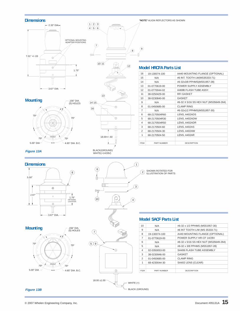
Model HRCFA Parts List
Model SACF Parts List
Dimensions
Dimensions
Mounting
Mounting
Figure 13B
Figure 13A

Quartz Type Flasher Replacements
The A450 and A470A remote anti-collision strobe lighthead assembliesare direct replacement for the quartz-type flasher, using the orig-inal or the H102 “B” mounting adapter.The H102 “B” mounting adapter is mounted in the aircraft’s structure,with four (4) MS 20470 AD4 rivets, or four (4) 6-32 screws and self-locking nuts. Drill out the center hole in the skin to allow access to thestrobe head connector.
MODEL A470A SERIESFAA/PMA APPROVEDModel Number Part Number DescriptionA470AR . . . . . . . . .01-0770019-18 . . . . . . . . . . . . . . . . . .standard assembly, Red lensA470AW . . . . . . . . .01-0770019-19 . . . . . . . . . . . . . . . .standard assembly, White lensA470AS . . . . . . . . .01-0770019-20 . . . . . . . . .standard assembly, Split Red/White lensA470ADR . . . . . . . .01-0770019-21 . . . . . . . . . . . . . .radio shielded assembly, Red lensA470ADW . . . . . . . .01-0770019-22 . . . . . . . . . . . .radio shielded assembly, White lensA470ADS . . . . . . . .01-0770019-23 . . . . .radio shielded assembly, Split Red/White lens
SpecificationsWeight . . . . . . . . . . . . . . . . . . . . . . . . . . . . . . . . . . . . . . . . . . . . . . . . . . . . . . . .0.3 lbs.Exposed Height . . . . . . . . . . . . . . . . . . . . . . . . . . . . . . . . . . . . . . . . . . . . . . . . . . .3.75”Diameter . . . . . . . . . . . . . . . . . . . . . . . . . . . . . . . . . . . . . . . . . . . . . . . . . . . . . . . . .2.5”
MODEL A450 SERIESFAA/PMA APPROVEDModel Number Part Number DescriptionA450 . . . . . . . . . . . .01-0770032-00 . . . . . . . . . . . . . . . . .standard assembly, Clear lens
SpecificationsWeight . . . . . . . . . . . . . . . . . . . . . . . . . . . . . . . . . . . . . . . . . . . . . . . . . . . . 0.3 lbs.Exposed Height . . . . . . . . . . . . . . . . . . . . . . . . . . . . . . . . . . . . . . . . . . . . . . . 2.25”Diameter . . . . . . . . . . . . . . . . . . . . . . . . . . . . . . . . . . . . . . . . . . . . . . . . . . . . . 2.5”
MODEL H102 & H103 SERIESModel Number Part Number DescriptionH102 . . . . . . . . . . .07-730068-000 . . . . . . . . . . . . . . . . . . . . . . . .flush mount adapterH103 . . . . . . . . . . .11-230079-000 . . . . . . . . . . . . . . . .rotating beacon mount adapter
Before with Quartz Light After with Remote Strobe Light
Model A470A Installation
H102 H103
16
STROBE LIGHTHEAD ASSEMBLIES
Document #05131A
∅2.485
.150
∅1.250BOLT CIRCLE
∅1.625BOLT CIRCLE
8X .136∅
∅1.00
Figure 14 H102 Mounting Adapter

Vertical Fin and Rudder Mounting of Anti-CollisionStrobe LightsRudder mounted anti-collision lights should be located top center ofthe rudder hinge center line, or rudder balance must be establishedafter installation. Refer to AC 43.13-2A, Chapter 4, Paragraph 55(e),“Rudder Installation”. The rudder or fin cap is excellent for shadowingthe prop and cabin area if the light is mounted far enough back.
NOTE: Mounting an A450 or A470A strobe lighthead assembly on avertical fin or rudder, can be accomplished by fabricating a mountingadapter similar to the ones shown in illustrations.
Fabrication and installation of these mounting brackets are referencedin this approved installation manual, and AC 43.13-1B and 2A.Documentation of structural integrity of the fabricated installation mustbe approved by an “IA” or other representative of the FAA. Conformityinspections will be performed with reference to approved techniques,and procedures specified in this manual (see page 3).
FIG. 15C FIG. 15D
Round or streamline tubing cut to fit rudder or vertical fin welded to 2 /12” OD.40” thick disc. (Reference AC 43.13-1B,
Chapter 2, Section 2).
Metal bracket shaped to fit the vertical fin orrudder with 2 1/2” OD .040” thick disc rivetedin place. (Reference AC 43.13-1B, Chapter 2).
QTY ITEM PART NUMBER
01-0770019-18 STROBE ASSY. - RED (A470A-R)
DESCRIPTION
68-2170504-50 LENS ASSY, (RED)
01-0450685-00 CLAMP RING .50Ø
38-0250429-00 GASKET, SHIELDED
01-0770044-02 FLASHTUBE ASSY (A469B)
2
3
4
5
6
8
9
01-0770019-19
01-0770019-20
01-0770019-21
01-0770019-22
01-0770019-23
STROBE ASSY. - WHITE (A470A-W)
STROBE ASSY. - RED/WHITE (A470A-R/W)
STROBE ASSY, R S - RED (A470A-D-R)
STROBE ASSY, R S - WHITE (A470A-D-W)
STROBE ASSY, R S - R/W (A470A-D-R/W)
LENS ASSY, (WHITE)68-2170504-30
LENS ASSY. (RED/WHITE)68-2170504-60
LENS ASSY, R S - (RED)68-2170504R50
LENS ASSY, R S - (WHITE)68-2170504R30
LENS ASSY, R S - (RED/WHITE)68-2170504R60
#6-32 X 1/2 PHILLIPS PHMS(MS51957-30)
10
111
1 1 1 1 1
11 1 1 1 1
11 1
1 1 1 1 1
1
1
1
1
1
1
3.50”
2.58” DIA
12
3
WHITEBLACK
RED
38-0230840-0012111 GASKET
*
*
*
*
*
*
15 N/A #6-32 X 5/16 SS HEX NUT (MS35649-264)1 1 1 1 1 1
1
1
6
THRU
8
9 12
10
15
11
- - - - - - 17 02-0350600-01 LENS ASSY, MASKED (WHITE)
17
A470A-
N/A
DESCRIPTIONPART NO.
68-4230044-30 LENS(CLEAR)
38-0230946-00 GASKET, LENS .046" THK
02-0350053-00 FLASH TUBE ASSY.1
2
3
4
5
6
A450 STROBE LIGHT HEAD ASSEMBLY
ITEMQTY.
* 01-0770032-00
#6-32 X 1/2 PHILLIPS PHMS(MS51957-30)
1
1
1
1
5
4
2
13
1
6
1 N/A #6-32 X 5/16 SS HEX NUT (MS35649-264)
01-0450685-00 CLAMP RING .50ر2.58”
2.15”
REMOVE RTV WHEN UNIT IS MOUNTEDIN AN INVERTED POSITION
A450
N/A
© 2007 Whelen Engineering Company, Inc. Document #05131A 17
Dimensions
Figure 15A
Figure 15B
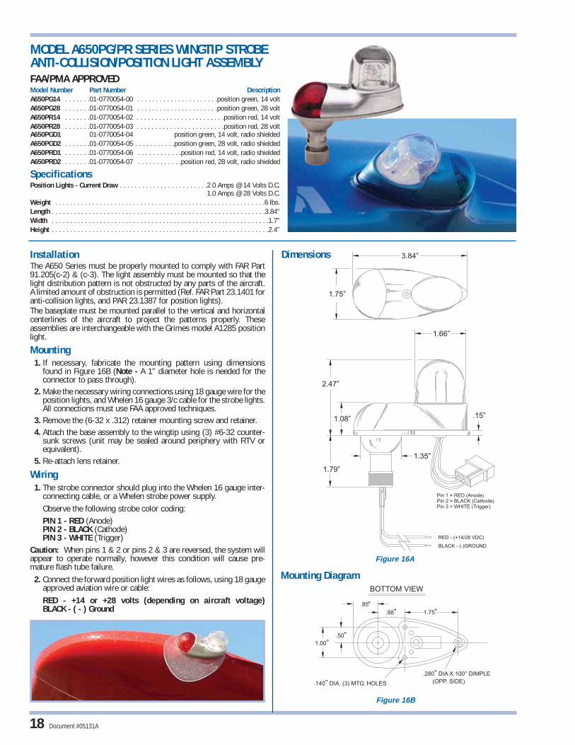
3.84”
1.75”
1.66”
2.47”
1.35”
.15”1.08”
RED - (+14/28 VDC)
Pin 1 = RED (Anode)Pin 2 = BLACK (Cathode)Pin 3 = WHITE (Trigger)
BLACK - (-)GROUND
1.79”
BOTTOM VIEW
1.00”
1.75
.85
.88”
.50”
.280 DIA X 100° DIMPLE”
.140 DIA. (3) MTG. HOLES” (OPP. SIDE)
””
InstallationThe A650 Series must be properly mounted to comply with FAR Part91.205(c-2) & (c-3). The light assembly must be mounted so that thelight distribution pattern is not obstructed by any parts of the aircraft.A limited amount of obstruction is permitted (Ref. FAR Part 23.1401 foranti-collision lights, and PAR 23.1387 for position lights).The baseplate must be mounted parallel to the vertical and horizontalcenterlines of the aircraft to project the patterns properly. Theseassemblies are interchangeable with the Grimes model A1285 positionlight.
Mounting1. If necessary, fabricate the mounting pattern using dimensions
found in Figure 16B (Note - A 1” diameter hole is needed for theconnector to pass through).
2. Make the necessary wiring connections using 18 gauge wire for theposition lights, and Whelen 16 gauge 3/c cable for the strobe lights.All connections must use FAA approved techniques.
3. Remove the (6-32 x .312) retainer mounting screw and retainer.4. Attach the base assembly to the wingtip using (3) #6-32 counter-
sunk screws (unit may be sealed around periphery with RTV orequivalent).
5. Re-attach lens retainer.
Wiring1. The strobe connector should plug into the Whelen 16 gauge inter-
connecting cable, or a Whelen strobe power supply.Observe the following strobe color coding:PIN 1 - RED (Anode)PIN 2 - BLACK (Cathode)PIN 3 - WHITE (Trigger)
Caution: When pins 1 & 2 or pins 2 & 3 are reversed, the system willappear to operate normally, however this condition will cause pre-mature flash tube failure.
2. Connect the forward position light wires as follows, using 18 gaugeapproved aviation wire or cable:RED - +14 or +28 volts (depending on aircraft voltage)BLACK - ( - ) Ground
Dimensions
18
MODEL A650PG/PR SERIES WINGTIP STROBE ANTI-COLLISION/POSITION LIGHT ASSEMBLYFAA/PMA APPROVEDModel Number Part Number DescriptionA650PG14 . . . . . . .01-0770054-00 . . . . . . . . . . . . . . . . . . . . . .position green, 14 voltA650PG28 . . . . . . .01-0770054-01 . . . . . . . . . . . . . . . . . . . . . .position green, 28 voltA650PR14 . . . . . . .01-0770054-02 . . . . . . . . . . . . . . . . . . . . . . . .position red, 14 voltA650PR28 . . . . . . .01-0770054-03 . . . . . . . . . . . . . . . . . . . . . . . .position red, 28 voltA650PGD1 01-0770054-04 position green, 14 volt, radio shieldedA650PGD2 . . . . . . .01-0770054-05 . . . . . . . . . . .position green, 28 volt, radio shieldedA650PRD1 . . . . . . .01-0770054-06 . . . . . . . . . . . .position red, 14 volt, radio shieldedA650PRD2 . . . . . . .01-0770054-07 . . . . . . . . . . . .position red, 28 volt, radio shielded
SpecificationsPosition Lights - Current Draw . . . . . . . . . . . . . . . . . . . . . . . .2.0 Amps @ 14 Volts D.C.
1.0 Amps @ 28 Volts D.C.Weight . . . . . . . . . . . . . . . . . . . . . . . . . . . . . . . . . . . . . . . . . . . . . . . . . . . . . . . . .6 lbs.Length . . . . . . . . . . . . . . . . . . . . . . . . . . . . . . . . . . . . . . . . . . . . . . . . . . . . . . . . . .3.84”Width . . . . . . . . . . . . . . . . . . . . . . . . . . . . . . . . . . . . . . . . . . . . . . . . . . . . . . . . . . .1.7”Height . . . . . . . . . . . . . . . . . . . . . . . . . . . . . . . . . . . . . . . . . . . . . . . . . . . . . . . . . . .2.4”
Mounting Diagram
Figure 16B
Figure 16A
Document #05131A
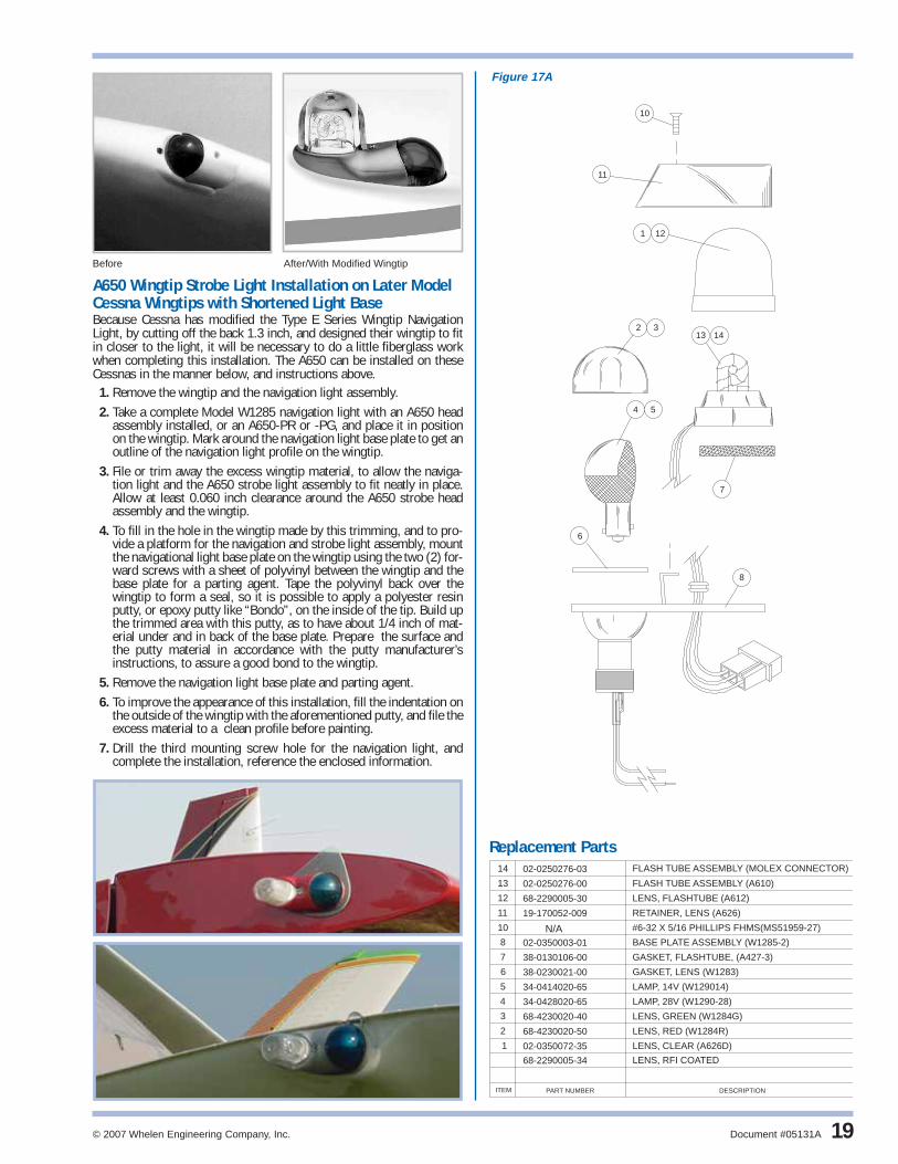
A650 Wingtip Strobe Light Installation on Later ModelCessna Wingtips with Shortened Light BaseBecause Cessna has modified the Type E Series Wingtip NavigationLight, by cutting off the back 1.3 inch, and designed their wingtip to fitin closer to the light, it will be necessary to do a little fiberglass workwhen completing this installation. The A650 can be installed on theseCessnas in the manner below, and instructions above.
1. Remove the wingtip and the navigation light assembly.2. Take a complete Model W1285 navigation light with an A650 head
assembly installed, or an A650-PR or -PG, and place it in positionon the wingtip. Mark around the navigation light base plate to get anoutline of the navigation light profile on the wingtip.
3. File or trim away the excess wingtip material, to allow the naviga-tion light and the A650 strobe light assembly to fit neatly in place.Allow at least 0.060 inch clearance around the A650 strobe headassembly and the wingtip.
4. To fill in the hole in the wingtip made by this trimming, and to pro-vide a platform for the navigation and strobe light assembly, mountthe navigational light base plate on the wingtip using the two (2) for-ward screws with a sheet of polyvinyl between the wingtip and thebase plate for a parting agent. Tape the polyvinyl back over thewingtip to form a seal, so it is possible to apply a polyester resinputty, or epoxy putty like “Bondo”, on the inside of the tip. Build upthe trimmed area with this putty, as to have about 1/4 inch of mat-erial under and in back of the base plate. Prepare the surface andthe putty material in accordance with the putty manufacturer’sinstructions, to assure a good bond to the wingtip.
5. Remove the navigation light base plate and parting agent.6. To improve the appearance of this installation, fill the indentation on
the outside of the wingtip with the aforementioned putty, and file theexcess material to a clean profile before painting.
7. Drill the third mounting screw hole for the navigation light, andcomplete the installation, reference the enclosed information.
1
2 3
4 5
6
7
8
12
10
11
13 14
PART NUMBER DESCRIPTIONITEM
10
1 02-0350072-35 LENS, CLEAR (A626D)
2 68-4230020-50 LENS, RED (W1284R)
LENS, GREEN (W1284G)68-4230020-403
GASKET, LENS (W1283)
LAMP, 14V (W129014)
LAMP, 28V (W1290-28)
38-0230021-00
34-0414020-65
34-0428020-65
6
5
4
38-0130106-00 GASKET, FLASHTUBE, (A427-3)
02-0350003-01 BASE PLATE ASSEMBLY (W1285-2)
7
8
#6-32 X 5/16 PHILLIPS FHMS(MS51959-27)
12
11
68-2290005-30
19-170052-009
LENS, FLASHTUBE (A612)
RETAINER, LENS (A626)
FLASH TUBE ASSEMBLY (A610)02-0250276-0013
FLASH TUBE ASSEMBLY (MOLEX CONNECTOR)02-0250276-0314
N/A
68-2290005-34 LENS, RFI COATED
Before After/With Modified Wingtip
Figure 17A
19
Replacement Parts
© 2007 Whelen Engineering Company, Inc. Document #05131A

Late Model Single Engine Cessna Wingtip Strobe LightInstallation of A610 and A612
1. Remove the position light lens retainer being careful not to drop thered or the green lens.
2. Establish a center line on the Cessna lens retainer, referencing tothe lens retainer center mounting screw, and position light baseplate rear mounting screw.
3. Scribe the A612 lens profile as shown in illustration above, theobject being to have the strobe light centered over the position lightbase plate.
4. Trim or fit an opening to the scribe line to fit the A612 lens. Due tothe uneven surface of the Cessna lens retainer, the A612 will con-tact only the front and rear radius.
5. Place the sponge rubber pad supplied under the A610 flash tube tofirm the assembly. RTV is recommended to secure lens in the mod-ified retainer.
6. The flash tube interconnecting cable is routed through square holesin the rear bulkhead of the position light area.
7. Install the modified position light lens retainer, A610 flash tube andA612 lens, using original hardware.
OperationThe Model A610 flash tube and the Model A612 glass lens are used for installing wingtip strobes in single engine Cessna’s 1972 and later. Theexisting position light retainer is modified to accommodate the lens, and the flash tube is mounted directly behind. The unique magnifying designof the A612 lens increases the light intensity by two to three times in the horizontal plane. Lenses meet material requirements of MIL-C-7989Bclass B.
1.682”
1.68”
1.75”
1.170”
1.00 RAD”
.375 RAD”
.240”
.125 WALL”1.28”
MIN. INSIDEHEIGHT
1.60”(APPROX)
POS 3 - WHITE (TRIGGER)
POS 2 - BLACK (CATHODE)
POS 1 - RED (ANODE)
CONNECTOR WIRING
A612 Dimensions
Before
After
AFTER
File to fitA612 lens
profile
CENTERLINE
A612
A610
A610 Dimensions
INSTALLATION OF MODEL A610Model Number Part Number DescriptionA610 . . . . . . . . . . . .02-0250276-00 . . . . . . . . . . . . . . . . . . . . . .standard unit, 6” leads
SpecificationsA610 Flash Tube Weight . . . . . . . . . . . . . . . . . . . . . . . . . . . . . . . . . . . . . . . . . .0.09 lbs.
MODEL A612Model Number Part Number DescriptionA612 . . . . . . . . . . . .68-2290005-30 . . . . . . . . . . . . . . . . . . . . . . . . .standard clear lensA612D . . . . . . . . . .68-2290005-34 . . . . . . . . . . . . . . . . . . . .radio shielded, clear lens
SpecificationsA612 Lens Weight . . . . . . . . . . . . . . . . . . . . . . . . . . . . . . . . . . . . . . . . . . . . . .0.08 lbs.
20
BEFORE
Figure 18B
Figure 18A Figure 18C
Document #05131A

A625 Strobe Light AssemblyThe A625 strobe lighthead assembly fits into a 1.1 inch hole. Themounting screws are 1.75 inch center to center. It protrudes 1.7 inchoutside the aircraft’s skin, and 1.1 inch inside the aircraft.When installing an A625 strobe lighthead assembly on the rudder,refer to the aircraft’s MAINTENANCE and/or SERVICE MANUAL foraccepted procedures for balancing the rudder before returning the air-craft to service.Mount the anti-collision strobe lighthead assembly as close to the sta-bilizer center line as practical, to eliminate backscatter as much aspossible for the horizontal surface.When installing the A625 strobe lighthead assembly in an enclosedarea like a Beech enclosed wingtip or tail cone, maintain at least 0.060inch clearance around the lens to the plastic cover. The A625 mountsconveniently just behind the forward position light on Cessna’s coni-cal camber wingtip. Make sure that the navigation light pattern is notinterrupted when installing the A625 strobe light head on a wingtip.The A612 lens is not considered an obstruction.
A625 INSTALLATION IN CESSNA 300 OR 400 SERIES WINGTIPTANKS. The A625 fits just under the navigation light, on an adapterplate of 0.032 inch aluminum, approximately 2-3/8 inches x 3-1/2inches. Fit this plate between the navigation light and its mountingsurface, and locate the A625 strobe head below the navigation light.
Bend and trim the adapter plate as necessary, so that the A625 clearsthe transparent window that covers the navigation light area 0.060inch minimum.The conduit for the navigation light wire is very small. To get the nec-essary wires to operate the strobe light and the navigation lightthrough this conduit, use a 20 gauge wire, with less that 0.060 inchOD. It has been found that the Belden 8502 or 8308, has an 0.058inch OD.
1 LENS, RFI COATED68-2290005-348
1
2
12
STROBE LIGHT ASSY. MODEL A625D* 01-0770058-13
2 N/A #4-40 HEX NUT, BRASS6
1
N/A #4-40 X 1/2 PPHMS (MS51957-17)2
GASKET,38-0250074-00
1
RETAINER, LENS19-170057-0091
LENS, CLEAR68-2290005-30
1
2
3
4
5 02-0370338-00 A627 FLASHTUBE ASSY.
1
STROBE LIGHT ASSY. MODEL A62501-0770058-03*ITEMQTY. DESCRIPTIONPART NUMBER
-
-
-
CL
POS 3 - WHITE (TRIGGER)POS 2 - BLACK (CATHODE)POS 1 - RED (ANODE)
CONNECTOR WIRING
1.09
1.93
2.12
1.40
2.80
5.50 ±.50"LEAD LENGTH
1.04 DIA.
.875
1.750
LC
3
4
5
6
2
1
8
Spare Parts
Dimensions
MODEL A625 SERIES INSTALLATIONFAA/PMA APPROVEDModel Number Part Number DescriptionA625 . . . . . . . . . . . .01-0770058-03 . . . . . . . . . . . . . . . . . . . . .standard unit, clear lensA625D . . . . . . . . . .01-0770058-13 . . . . . . . . . . . . . . . . . . . .radio shielded, clear lens
SpecificationsWeight . . . . . . . . . . . . . . . . . . . . . . . . . . . . . . . . . . . . . . . . . . . . . . . . . . . . . . . .0.2 lbs. Exposed Height . . . . . . . . . . . . . . . . . . . . . . . . . . . . . . . . . . . . . . . . . . . . . . . . . . . .1.7”
© 2007 Whelen Engineering Company, Inc. Document #05131A 21
Figure 19A

Installation1. Remove the Model S tail position light by removing the two (2)
retainer ring screws.
2. This unit fits directly in place of theGrimes Model S tail position light. It ishowever sometimes necessary to openthe mounting hole in the aircraft fairing to 1.10 inch, to clear the body of the A500A. The body protrudes 1.40 inch into the tail fairing.
3. Establish the proper light pattern of the A500A tail position light.The retainer shield must be located so that the bottoms of the Vnotches are vertical (parallel to the rudder) to shadow the light soit will produce a horizontal light pattern of 70 degrees left and rightof straight back of aircraft.
MODEL A500A SERIES INSTALLATIONFAA/PMA APPROVEDModel Number Part Number DescriptionA500AV14 . . . . . . . .01-0770024-00 . . . . . . . . . . . . . . . . . . . . . .vertical mount, 14 voltA500AV28 . . . . . . . .01-0770024-01 . . . . . . . . . . . . . . . . . . . . . .vertical mount, 28 voltA500AH14 . . . . . . .01-0770024-02 . . . . . . . . . . . . . . . . . . . .horizontal mount, 14 voltA500AH28 . . . . . . .01-0770024-03 . . . . . . . . . . . . . . . . . . . .horizontal mount, 28 voltA500AVD1 . . . . . . .01-0770024-04 . . . . . . . . . . .vertical mount, 14 volt, radio shieldedA500AVD2 . . . . . . .01-0770024-05 . . . . . . . . . . .vertical mount, 28 volt, radio shieldedA500AHD1 . . . . . . .01-0770024-06 . . . . . . . . .horizontal mount, 14 volt, radio shieldedA500AHD2 . . . . . . .01-0770024-07 . . . . . . . . .horizontal mount, 28 volt, radio shielded
SpecificationsWeight . . . . . . . . . . . . . . . . . . . . . . . . . . . . . . . . . . . . . . . . . . . . . . . . . . . . . . . .0.3 lbs.Exposed Height . . . . . . . . . . . . . . . . . . . . . . . . . . . . . . . . . . . . . . . . . . . . . . . . . . . .1.7”Diameter . . . . . . . . . . . . . . . . . . . . . . . . . . . . . . . . . . . . . . . . . . . . . . . . . . . . . . . . .1.5”
OperationCombination Strobe/Tail Navigation Light used when the wingtip anti-collision lights are mounted in an enclosure and can’t provide 360º ofstrobe coverage. It is a direct replacement for the standard tail position light. Available in a radio-shielded version. Voltage (14 or 28), andmounting, (horizontal or vertical) must be specified when ordering.
Dimensions
22
CONNECTING WIRING OF THE A500A TO THE A441 AMP 3 POSITION PIN CONNECTOR HOUSING, AND THE A444 AMP 2 POSITION PIN HOUSING CONNECTOR.
Anode RED wire Pin 1 of A441Cathode BLACK wire Pin 2 of A441Trigger WHITE wire Pin 3 of A441Position Light A+ BLUE wire Pin 1 of A444Position Light Ground BLUE wire Pin 2 of A444
70 (REF)°
WIRE EXIT (REF)
.19”
1.06” DIA.
1.40”1.65”
2.80”
2.17”
1.75”
1.71”
70 (REF)°
HORIZONTALMOUNTING
1.75"
1.75"
1.40"
HORIZONTAL VERTICAL MOUNTINGSURFACE
FIG. 20B
VERTICALMOUNTING
Figure 20A
Document #05131A

A500A-H-28A500A-H-14A500A-V-28A500A-V-14
3
8
1
5
4
6
7
7.00" 1.00 LEADS±
12.00" 1.00 LEADS±
12
2
32
17
19
32
14
2
BONDING BRAID12.00" 1.00"±7.00" 1.00"±
6.00" 1.00"±
3
A500A-V-D-14A500A-V-D-28A500A-H-D-14A500A-H-D-28
A500A-V-D-M-14A500A-V-D-M-28A500A-H-D-M-14A500A-H-D-M-28
5
76
8
J2 CONNECTOR WIRING
POS 1 - RED(ANODE)POS 2 - BLACK(CATHODE)POS 3 - WHITE(TRIGGER)
J1 CONNECTOR WIRING
POS 1 - BLUE(+)POS 2 - BLUE(-)GROUND
J1
J2
*
*
*
*
*
*
*
*
----
-- -- --
--
1111
1 1 1 1
2 2222222
1 1
1 1
1
1 1
1 1 1 1 1 1 1
1 1 1
1
11
1 1
2 2 2 2 2 2 2
15
14 FLASH TUBE AND SOCKET ASSY (A506D)02-0350375-00
01-0770024-07
01-0770024-06
01-0770024-05
01-0770024-04
01-0770024-03
01-0770024-02
01-0770024-01
FLASH TUBE AND SOCKET ASSY (A506)02-0350034-00
LAMP,ESG HALOGEN (28 VOLT) (A508-28)34-0428070-64
TAIL POS & STROBE LT ASSY (A500A-H-28)
TAIL POS & STROBE LT ASSY (A500A-H-14)
TAIL POS & STROBE LT ASSY (A500A-V-14)
TAIL POS & STROBE LT ASSY (A500A-V-D-14)
TAIL POS & STROBE LT ASSY (A500A-V-D-28)
TAIL POS & STROBE LT ASSY (A500A-H-D-14)
TAIL POS & STROBE LT ASSY (A500A-H-D-28)
12
8
71
6
51
41
31
2
2 1
LENS, RFI COATED68-4270002-34
HEX NUT,#4-40 X 1/4 A.F. BRASS
LAMP,ERC HALOGEN (14 VOLT) (A508-14)34-0412070-63
GASKET (A455)38-0230002-00
CLEAR GLASS PLAIN DOME (A457A)68-4270002-30
RETAINER,MASK(VERTICAL)19-0150350-02
RETAINER,MASK(HORIZONTAL)19-0150350-01
#4-40 X 1/2 PHILLIPS PHMS(MS51957-17)
DESCRIPTION
TAIL POS & STROBE LT ASSY (A500A-V-28)
01-0770024-00
PART NUMBERITEMQUANTITY
-------- 19
321 1 1 1 1 1 1 1 46-0750698-00 PIGTAIL
02-0350375-01 FLASH TUBE AND SOCKET ASSY (A506DM)
1
= N/A•
= N/A•
15
11
© 2007 Whelen Engineering Company, Inc. Document #05131A 23
A500A Spare Parts
Figure 21A
Model A500A Installation

Wiring1. The strobe connector should plug into the Whelen interconnecting
cable, or a Whelen strobe power supply. Observe the following strobe color coding:
PIN 1 - RED (Anode)PIN 2 - BLACK (Cathode)PIN 3 - WHITE (Trigger)
Caution: When pins 1 & 2 or pins 2 & 3 are reversed, the systemwill appear to operate normally, however this condition will causepre-mature flash tube failure.
2. Connect the forward position light wires as follows:RED - +14 or +28 volts (depending on aircraft voltage)BLACK - ( - ) Ground
3. The tail position light has no polarity, as noted by both wires beingBLUE. Connect one BLUE wire to +14 or +28 volts (depending onaircraft voltage). Connect the other BLUE wire to ground (see fig-ure 22B)
Dimensions
OperationWingtip anti-collision, forward position, and tail position lights, all in one compact unit. Tail position light eliminates the need for a tail mounted position light. Available in 14 or 28 volts, and in a radio-shielded version. The forward position lamp is 26 watts and the taillight lamp is 25 watts.
InstallationThe A600 Series must be properly mounted to comply with FAR Part91.205(c-2) & (c-3). The light assembly must be mounted so that thelight distribution pattern is not obstructed by any parts of the aircraft.A limited amount of obstruction is permitted (Ref. FAR Part 23.1401 foranti-collision lights, and PAR 23.1387 for position lights).The convergence of the two wingtip tail position must occur within1200 feet directly behind the aircraft to comply with field of coveragerequirements. The baseplate must be mounted parallel to the vertical &horizontal centerlines of the aircraft to project the patterns properly.
Mounting1. If necessary, fabricate the mounting pattern using dimensions
found in figure 22A.2. Make the necessary wiring connections using 18 gauge wire for the
position lights, and Whelen 16 gauge 3/c cable for the strobe lights.All connections must use FAA approved techniques.
3. Remove the two (6-32 x .312) retainer mounting screws and retainer.
4. Attach the base assembly to the wingtip using (3) #6-32 counter-sunk screws (unit may be sealed around periphery with RTV orequivalent).
5. Re-attach lens retainer (see figure 23A).
MODEL A600 PG/PR SERIES INSTALLATIONFAA/PMA APPROVEDModel Number Part Number DescriptionA600PG14 . . . . . . .01-0790006-00 . . . . . . . . . . . . . . . . . . . . . .position green, 14 voltA600PG28 . . . . . . .01-0790006-01 . . . . . . . . . . . . . . . . . . . . . .position green, 28 voltA600PR14 . . . . . . .01-0790006-02 . . . . . . . . . . . . . . . . . . . . . . . .position red, 14 voltA600PR28 . . . . . . .01-0790006-03 . . . . . . . . . . . . . . . . . . . . . . . .position red, 28 voltA600PGD1 . . . . . . .01-0790006-04 . . . . . . . . . . .position green, 14 volt,radio shieldedA600PGD2 . . . . . . .01-0790006-05 . . . . . . . . . . .position green, 28 volt, radio shieldedA600PRD1 . . . . . . .01-0790006-06 . . . . . . . . . . . .position red, 14 volt, radio shieldedA600PRD2 . . . . . . .01-0790006-07 . . . . . . . . . . . .position red, 28 volt, radio shielded
SpecificationsPosition Lamps Power Consumption Total . . . . . . . . . . . . . . . . . .4.0 Amps @ 14 VDC;
. . . . . . . . . . . . . . . . . . . . . . . . . . . . . . . . . . . . . . . . . . . . . . . . . .2.0 Amps @ 28 VDCWeight . . . . . . . . . . . . . . . . . . . . . . . . . . . . . . . . . . . . . . . . . . . . . . . . . . . . . . . .0.8 lbs.Length . . . . . . . . . . . . . . . . . . . . . . . . . . . . . . . . . . . . . . . . . . . . . . . . . . . . . . . . . .5.63”Width . . . . . . . . . . . . . . . . . . . . . . . . . . . . . . . . . . . . . . . . . . . . . . . . . . . . . . . . . . .1.7”Exposed Height . . . . . . . . . . . . . . . . . . . . . . . . . . . . . . . . . . . . . . . . . . . . . . . . . . . .2.4”
24
.50”1.00”
.88”
1.75”
.140” DIA. (3)MOUNTING HOLESFOR #6-32 SCREWS
18 AWG TEFLON
1.79”
110°70°
1.08”.15”
1.35”DIA.
1.66”
RED (+14 or +28VDC)
BLACK (-) GROUND
POS 1 - RED(ANODE)POS 2 - BLACK(CATHODE)POS 3 - WHITE(TRIGGER)
TAIL LIGHT WIRES(BLUE)NO POLARITY
LEAD LENGTH 6.00"±1.00"
2.46”
1.83”
5.63”
Figure 22A Figure 22B
Document #05131A

© 2007 Whelen Engineering Company, Inc. Document #05131A 25
13
17
18 16
1
5 6
2
12
14
10 11
8
43
7
9
ITEM PART NUMBER DESCRIPTION
1 BASEPLATE ASSY.(A605)
2
3 LAMP, 14V(W1290-14)
4 LAMP, 28V(W1290-28)
5 LENS, GREEN(W1284-G)
02-0350259-00
8
7
6
34-0414020-65
34-0428020-65
68-4230020-40
19-170049-009
LENS, RED(W1284-R)
LENS RETAINER(A606)
10
11
12
9
13
LENS, TAIL POSITION(A615)
LAMP, 28V(A508-28)
68-4250066-30
34-0428070-64
34-0412070-63
02-0350260-00
LAMP, 14V(A508-14)
SOCKET ASSY.(A507)
68-4230020-50
38-0230021-00 GASKET(W1283)
14 GASKET(A616)38-0130090-00
N/A #6-32 X 5/16 PHILLIPS FHMS (MS51959-27)
02-0250276-00 FLASH TUBE ASSEMBLY(A610)
68-2290005-34 LENS, RFI COATED16
17 38-0130107-00 GASKET(A427-4)
68-2290005-3018 LENS, CLEAR(A612)
A600 Replacement Parts
Figure 23A
Model A600 Installation

A650 OperationConverts existing Whelen W1285 position lights into a position/anti-collision light system by removing the existing retainer and replacing itwith the A650 assembly. Available in a radio-shielded version.
A650 Wingtip Strobe Light.To install the Whelen A650 strobe lighthead assembly on the aircraft,proceed with the following instructions:1. Remove the wingtip navigation light and wingtip, when necessary.2. Install the nylon three position AMP pin connectors A441 on the
end of the flash tube wires (RED in pin 1, BLACK in pin 2, andWHITE in pin 3).
3. Assemble the navigation light assembly on the wingtip using theA650 strobe light assembly as the navigation light lens retainer.
a. Install the rubber pad (supplied in kit) on the position light baseplate under the A610 flash tube, if necessary to make the lens firmin its mounting.
4. In some installations it will be necessary to mask the A650 strobelight, to reduce pilot annoyance. The Navigation Light Detector willbe a source of reflection, and should be reduced in size or maskedas necessary. A small aluminum or plastic plate, mounted betweenthe navigation light and the wingtip, protruding up or down asrequired (like some plastic navigation light detectors), and trimmedto shadow the objectionable reflected area, is most effective. Thisreflection problem varies from one aircraft to another, due to aircraftdesign and paint color scheme, and must be checked on everyinstallation.
Dimensions
26
MODEL A650 SERIES INSTALLATIONFAA/PMA APPROVEDModel Number Part Number DescriptionA650 . . . . . . . . . . . .01-0770053-00 . . . . . . . . . . . . . . . . . . . . . . . . . . . . .standard unitA650D . . . . . . . . . .01-0770053-13 . . . . . . . . . . . . . . . . . . . . . . . . . . . . .radio shielded
Specifications:Weight . . . . . . . . . . . . . . . . . . . . . . . . . . . . . . . . . . . . . . . . . . . . . . . . . . . . . . . .0.2 lbs. Exposed Height . . . . . . . . . . . . . . . . . . . . . . . . . . . . . . . . . . . . . . . . . . . . . . . . . . . .2.4”
Before
After/with Modified Wingtip
7
4
2
5
CONNECTOR WIRING
POS 1 - RED(ANODE)POS 2 - BLACK(CATHODE)POS 3 - WHITE(TRIGGER)
1
PART NUMBER DESCRIPTIONQTY. ITEM
01-0770053-00 A650 STROBE ASSY.
1 1
68-2290005-34 LENS RFI COATED2
68-2290005-30 LENS, CLEAR(A612)
FLASHTUBE ASSEMBLY(A610)
RETAINER,LENS(A626)
02-0250276-00
19-170052-009
5
4
1
1
01-0770053-13 A650-D STROBE ASSY.(SHIELDED/CLEAR)
-
1
1 -
-
1 1 A427-3 GASKET38-0130106-007
*
*
2.70”
1.75”
TOP VIEW
2.03”
.90”
2.40”
1.66”
LEADS ARE6.00 1.0" LONG±
SIDE VIEW
A650 Spare Parts
Figure 24A
Figure 24B
Document #05131A

STROBE POWER SUPPLY CROSS REFERENCE REPLACEMENT LISTING
Model HDACFP/N 01-0770028-05
Model A490TSCP/N 01-0770062-03
Model HTCFP/N 01-0770006-08
Model HTCCFP/N 01-0770006-09
Model HRCFAP/N 01-0770029-( )Specify lens colorR=Red, W=WhiteS=Split Red/White
© 2007 Whelen Engineering Company, Inc. Document #05131A 27
Old Part Number Old Model Number Description Current Replacement
A413,HS-41-14 HS,41 Single strobe unit, SingleFlash, 14 VDC, 33 joule
A413,HS-41-28 HS,41 Single strobe unit, SingleFlash, 28 VDC, 33 joule
A413,HD-14 HD Dual strobe unit, SingleFlash, 14 VDC, alternating
A413,HD-28 HD Dual strobe unit, SingleFlash, 28 VDC, alternating
A413,HD-42-14 HD,42 Dual strobe unit, SingleFlash, 14 VDC, alternating 33 joule
A413,HD-42-28 HD,42 Dual strobe unit, SingleFlash, 28 VDC, alternating 33 joule
A413,T2-14 HD,T2 Dual strobe unit, SingleFlash, 14 VDC, simultaneous, 16 joule
A413,T2-28 HD,T2 Dual strobe unit, SingleFlash, 28 VDC, simultaneous, 16 joule
A413,T2-DF-14 HD,T2,DF Dual strobe unit, DoubleFlash, 14 VDC, simultaneous, 16 joule
A413,T2-DF-28 HD,T2,DF Dual strobe unit, DoubleFlash, 28 VDC, simultaneous, 16 joule
A413,T3-14 HD,T3 3 strobe unit, SingleFlash, 14 VDC, w/trigger function
A413,T3-28 HD,T3 3 strobe unit, SingleFlash, 28 VDC, w/trigger function
A413,HD,DF-14 HD,DF 3 strobe unit, DoubleFlash, 14 VDC
A413,HD,DF-28 HD,DF 3 strobe unit, DoubleFlash, 28 VDC
A413,T3-DF-14 HD,T3,DF 3 strobe unit, DoubleFlash, 14 VDC, w/trigger function
A413,T3-DF-28 HD,T3,DF 3 strobe unit, DoubleFlash, 28 VDC, w/trigger function
A413A,HDA-DF-14 HDA,DF-14 4 strobe unit, DoubleFlash, 14 VDC
A413A,HDA-DF-28 HDA,DF-28 4 strobe unit, DoubleFlash, 28 VDC
A413A,HDA-DF-14/28 HDA,DF-14/28 4 strobe unit, DoubleFlash, 14 or 28 VDC
A413A,HDA-CF-14/28 HDA,CF-14/28 4 strobe unit, CometFlash®, 14 or 28 VDC
A412A,HS-14 HS,14 Single strobe unit, SingleFlash, 14 VDC
A412A,HS-28 HS,28 Single strobe unit, SingleFlash, 28 VDC
A412A,HS,DF-14 HS,DF-14 Single strobe unit, DoubleFlash, 14 VDC
A412A,HS,DF-28 HS,DF-28 Single strobe unit, DoubleFlash, 28 VDC
A490,TS-14 HTS Single strobe unit, SingleFlash, 14 VDC
A490,TS-28 HTS Single strobe unit, SingleFlash, 28 VDC
A490A,TS,DF HTS-DF Single strobe unit, DoubleFlash, 14 or 28 VDC
A490A,TS,CF-14/28 HTS-CF Single strobe unit, CometFlash®, 14 or 28 VDC
A490,T-14 HT Single strobe unit, SingleFlash, 14 VDC
A490,T-28 HT Single strobe unit, SingleFlash, 28 VDC
A490,T,DF-14 HT,DF Single strobe unit, DoubleFlash, 14 VDC
A490,T,DF-28 HT,DF Single strobe unit, DoubleFlash, 28 VDC
A490,T,DF-14/28 HT,DF Single strobe unit, DoubleFlash, 14 or 28 VDC
A490,T,CF-14/28 HT,CF Single strobe unit, CometFlash®, 14 or 28 VDC
A490,TC,DF-14 HTC,DF Single strobe unit, DoubleFlash, 14 VDC w/mtg. plate
A490,TC,DF-28 HTC,DF Single strobe unit, DoubleFlash, 28 VDC w/mtg. plate
A490,TC,DF-14/28 HTC,DF Single strobe unit, DoubleFlash, 14 or 28 VDC w/mtg. plate
A490,TC,CF-14/28 HTC,CF Single strobe unit, CometFlash®, 14 or 28 VDC w/mtg. plate
HR,14 Self-Contained Strobe, 14 VDC
HR,28 Self-Contained Strobe, 28 VDC
HR,DF,14 Self-Contained Strobe, DoubleFlash 14 VDC
HR,DF,28 Self-Contained Strobe, DoubleFlash 28 VDC
HR,DF,14/28 Self-Contained Strobe, DoubleFlash 14 or 28 VDC
HR,DFA,14/28 Self-Contained Strobe, DoubleFlash 14 or 28 VDC (A402A lens)

28
Inspect Lens
Excessivescratches,
discolorationsor cracking?
Replace LensYes
No
Check LensMounting
Loose ormissing
hardware?
Tighten orReplace
Yes
No
CheckOperation
ImproperOperation?
Check wiringand connections
Yes
Complete
No
Refer totrouble-shootingprocedures forstrobe lights
CONTINUED AIRWORTHINESS FLOW CHART
Document #05131A
TROUBLE-SHOOTING PROCEDURES FOR AVIATION ANTI-COLLISION STROBE LIGHT SYSTEMSWHEN REPAIRING WHELEN ANTI-COLLISION STROBE LIGHT SYS-TEMS, USE ONLY WHELEN FAA APPROVED HARDWARE. BE CAREFULOF STROBE LIGHT PARTS THAT ARE SIMILAR IN APPEARANCE!The Whelen Aviation Strobe Light is a condenser discharge strobe lightsystem. A condenser is charged to approximately 450 volts DC, thendischarged across a xenon flash tube at controlled intervals. The con-denser is parallel across the xenon flash tube that is designed to holdoff the 450 volts DC applied, until the flash tube is triggered by anexternal pulse. This pulse is generated by a solid-state timing circuit inthe power supply.When trouble-shooting a strobe light system, first determine if thetrouble is with the flash tube or the power supply. This can be accom-plished by replacing the flash tube assembly with a good operatingflash tube, or with the use of a Whelen Strobe Check unit.Whelen’s power supplies are protected against a short or open circuiton the output. In either case, the power supplies will effectively turnthemselves off when subjected to a shorted output of a xenon flashtube that refuses to flash.WARNING: Strobe light power supplies are meant to be used, not toremain in an inactive state. Use them at all times, this will improve theirproper functioning. Any strobe light power supply that has been out ofservice for a long period of time is subject to failure because the elec-trolytic condenser loses the polarity formation. A strobe light powersupply not having been used for one year or longer is vulnerable tofailure, applies to 1993 & older units.If this is the case, it is recommended to start operating the system ona voltage that is reduced by 25 percent for 10 to 15 minutes before put-ting the power supply into normal service. This will prevent overheat-ing of the condenser while they reform. If the power supply, after a longperiod of non use, is operated at full voltage immediately, there is anexcellent possibility that the condenser will become overheated.
A normal operating power supply emits an audible tone. If there is nosound emitted, investigate.
1. Determine that there is a proper input voltage at the power supply.If this test is positive go to step 2.
2. Clear all possible shorts at the power supply, by disconnecting theoutput cables from the power supply outlets, and connect an oper-ating strobe lighthead assembly or a Strobe Check unit directly tothe power supply outlet, then apply the required voltage to thepower supply input. If this application proves positive the powersupply is in working condition, and the problem may be with theinterconnecting cables.
CABLE CONTINUITY CHECK PROCEDURESIf pins 1 and 3 are reversed, or if there is a short between pins 1 and 2of the interconnecting cable, the power supply will be rendered non-operable until the short is cleared. A short of this type will not causeany permanent damage to the power supply. However a discharge ofthe condenser across pin 1 and pin 3 will destroy the trigger circuit inthe power supply.
1. Check for continuity between the connectors of each interconnect-ing cable:
Pin 1 to pin 1 (red wire = anode +).Pin 2 to pin 2 (black wire = flash tube ground -).Pin 3 to pin 3 (white wire = trigger).
2. Check for shorts between pins 1 and 2, pins 1 and 3, and pins 2and 3 of the interconnecting cable.
NOTE: When pins 1 and 2, or pins 2 and 3 are reversed, the system willappear to operate normally, but these conditions will cause early flashtube failure, and void the flash tube warranty.
XENON FLASH TUBE PROCEDURES1. A xenon flash tube can be very photosensitive. One will flash nor-
mally when exposed to an external light source, but may becomehard to fire when subjected to darkness.
2. They will become hard firing with age, or when exposed to a veryhigh temperature. A hard firing tube will sometimes operate withthe engine running, but will fail when operated on a low battery.
3. They can develop a leak through eggshelling of the glass, or a leakcan develop around the seal of the wire to the glass. This is causedby hot and cold cycling of normal operating of the system.
4. They can go into self-ionization (continuously glow a light blue),thus rendering the entire system non-operational until flash tube isreplaced. This most likely occurs when the input voltage is highest.This can be checked by turning the system off. When turning thesystem back on, it generally will operate normally for a few flashesbefore going back into self-ionization.
ANY OF THE ABOVE MENTIONED CONDITIONS ARE REASONS FORREPLACEMENT OF THE XENON FLASH TUBE.NOTE: Installing one new flash tube in any multi-head strobe light sys-tem, will sometimes cause the remaining old flash tube to misfire orskip. This signifies that the old flash tube is nearing the end of it’s serv-ice life. However, to check the questionable flash tube, install it in a sys-tem and apply a reduced voltage, approximately 20 percent, to theinput to the power supply. If the flash tube will operate at this reducedlevel, it still has a great deal of service life in it.
NOTE: Whelen Engineering does not recommend attempting to repairtheir strobe light power supplies in the field. It is recommended to takeadvantage of our 48-hour Repair Service.
© 2007 Whelen Engineering Company, Inc. Document #05131A 29
POWER SUPPLY TEST PROCEDURESTHE POWER SUPPLY IS A HIGH VOLTAGE DEVICE. LET THEPOWER SUPPLY BLEED DOWN FOR 10 MINUTES AFTERTURNING OFF POWER BEFORE HANDLING.WARNING: Reverse polarity of the input power, for just aninstant, will permanently damage the power supply. This dam-age is sometimes not immediately apparent, but will cause fail-ure later on.External trigger switching is not provided on the A413A, HDA-DF Strobe Light Power Supply (Reference A413,T3-DF old stylestrobe light power supply, outlet #1). Do not short out high volt-age for extended length of time; it will cause overheating of theoutput diodes and cause possible failure. WHELEN’S (CometFlash® “CF” Strobe Light System)
consists of four high energy pulses per burst of light, 45bursts of light per light.
STROBE SYSTEM TROUBLE-SHOOTING

R.F.I. and E.M.I. Problems (Radio Noise)Whelen Engineering strobe light power supplies are designed with alow pass filter built in to keep R.F.I. and E.M.I. down to a minimum,however, sometimes there will be interference in the radios by thestrobe light system. Most always, this is an installation problem, not astrobe light power supply problem.The power supply should acquire its power from a low impedancesource, such as the alternator or generator end of the electrical buss.Historically, the rotating beacon or strobe light circuit breaker is addedon the electrical buss at the opposite end, with the radio in between thestrobe breaker and the low impedance end of the electrical buss. Anynoise generated by the power supply will be transmitted into the radiothrough the A+ input lead to the radio. Most of the new radio equip-ment manufactured today has inadequate input filtering, and any noiseon the electrical buss is amplified in the radio and produced throughthe speaker and/or head phones loud and clear.Two things can be done to alleviate the problem:
1. Connect the strobe light circuit breaker to the low impedance endof the electrical buss, using a 16 gauge jumper, as close to thebattery as possible.
2. Install additional filtering in the radio A+ line, or provide an iso-lated A+ source for the radios by installing a filter choke in serieswith the radio input power lead and a filter adapter to ground andreference all radios to their filter. This will also improve the radiosystem from other line noises. REF 2200 mfd@50V Capacitor.
Frequently the noise is not on the A+ lead but is conducted through theground circuit. Alternator, electrical motor, fuel pumps and strobe lightpower supplies draw heavy current through the ground circuit of theaircraft’s frame. Any voltage drop in the ground circuit between the bat-tery ground and the radio ground can look like a signal to the radios.
When the speaker, head phone and microphone use the aircraft’sground for return to the radios, one will always experience some inter-ference. The amount of interference depends upon how much potentialdifference there is between the two ground points. Isolating the audiogrounds from the airplane ground at the speaker, head phone andmicrophone junctions, and grounding the aforementioned with theradio at one central ground point, will eliminate the majority of allground inducted radio noise.Do not parallel any audio leads with any power lead supplying energyto a noise generator; (i.e.) alternator, electric motor or DC chopperssuch as inverters and strobe light power supplies.The interconnecting cable between the power supply and the remotestrobe lighthead assembly radiate very little, for the output circuit of thepower supply is very low impedance. They can radiate RF like an anten-na if the shield is not terminated to ground. The radiation of RF energyis reduced to a minimum by properly terminating the shield at one endor the other, generally the power supply end, but which ever proves thequietest ground. Do not terminate both ends.When installing a strobe light system, provide a good ground and a lowimpedance source to the strobe light power supply. Eliminate groundloops in audio circuits by using a centrally located ground point for allaudio grounds.Whelen Engineering has available RF shielded flash tubes and strobelighthead assemblies to suppress the trigger pulse or clicking some-times heard in the radios.If noise problems persist, and the procedures described have notcleared them up, please contact the Whelen Engineering Company forassistance.
30
STROBE SYSTEM TESTERDescriptionA strobe system tester designed to determine the reason the strobe light system is not working properly. This kit contains an instructionsheet and a trouble shooting procedure sheet. Test power supplies andinterconnecting cables. It also comes with an adapter for testing Grimes and Hoskins strobe light systems. Model Number Part Number Description6542600 . . . . . . . . . .01-0765246-00 . . . . .Strobe System TesterPlease Order Part Number: 01-0765246-00.
Photos Show Typical Installations
Document #05131A

Model Number Part Number Description
5068500 01-0450685-00 Clamp Ring Assy.
A402AR 68-2170504-50 Optic Lens, Red
A402AS 68-2170504-60 Optic Lens, Split, Red/White
A402AW 68-2170504-30 Optic Lens, White
A424 11-430005-100 Taillight, Mounting Cup
A425 19-130000-100 Taillight, Lens Retainer
A425AH 19-0150350-01 Retainer, Horizontal Mount
A425AV 19-0150350-02 Retainer, Vertical Mount
A426 19-190000-009 Retainer for A428 Lens
A427 02-0250274-00 Strobe Tube Assy.
A427-4 38-0130107-00 Gasket/Spacer for A428 Lens
A428 68-4290001-30 Lens
A428C 02-0350033-00 Lens, Radio Shielded
A428D 02-0350057-00 Lens/Retainer Assy Radio Shielded
A435 02-0350054-00 Strobe Tube Assy, A430 Series
A440 19-130074-009 Mounting Adapter Ring
A441 01-0430011-00 Kit, 3 Pin Connector & contacts
A442 01-0410823-00 Kit, 3 Socket Connector & contacts
A443 02-0230081-00 Trigger Jumper Plug for HDACF
A444 02-0230007-00 Kit, 2 Pin Connector & contacts
A446 02-0230085-00 Kit, 2 Socket Connector & contacts
A455 38-0230002-00 Gasket, A457A Lens
A457A 68-4270002-30 Lens
A457AD 02-0350038-35 Lens, Shielded
A457BDH 02-0350038-37 Lens/Retainer Assy, Radio Shielded, Vertical Mounting
A457BDV 02-0350038-36 Lens/Retainer Assy, Radio Shielded, Horizontal Mounting
A469A 01-0770044-00 Strobe Tube Assy.(non reflective base)
A469B 01-0770044-02 Strobe Tube Assy.
A469D 01-0770044-01 Radio Shielded Strobe Tube Assy.
A469DK 01-0710834-00 Radio Shielding Kit for A469A
A504 06-150058-001 Disc, Lamp Socket for A555A Series
A506 02-0350034-00 Strobe Tube/Socket Assy. For A500A
A507 02-0350260-00 Lamp Socket for A555A Series
A50814 34-0412070-63 Halogen Lamp 14V 25 Watt
A50828 34-0428070-64 Halogen Lamp 28V 25 Watt
A605 02-0350259-00 Base Plate Assy. For A600 Series
A606 19-170049-009 Retainer for A600 Series
A610 02-0250276-00 Strobe Tube
A612 68-2290005-30 Magnifying Lens for A610
A612D 02-0350071-35 Lens/Retainer Assy. Radio Shielded used on A600 Series
A615 68-4250066-30 Taillight Lens used on A600 Series
A616 38-0130090-00 Gasket for A615 Taillight Lens
A626 19-170052-009 Retainer for A650 Series
A626D 02-0350072-35 Lens/Retainer Assy. for A650 Series, Radio Shielded
H102 07-730068-000 Mounting Adapter for A470A Series
H103 11-230079-000 Mounting Adapter for A470A Series3-3/4 dia mounting pattern
SA402 68-4230044-30 Lens, Clear for SACF & A450 Series
SA406 02-0350053-00 Strobe Tube for SACF & A450 Series
SA4181 38-0230104-00 Gasket for SA402 Lens
W1282 19-150002-009 Lens Retainer for W1285 Series
W1283 38-0230021-00 Gasket for W1284 Lens
W1284G 68-4230020-40 Position Light Lens, Green
W1284R 68-4230020-50 Position Light Lens, Red
W12852 02-0350003-01 Base Plate Assy.
W129014 34-0414020-65 Position Light Lamp, 14V
W129028 34-0428020-65 Position Light Lamp, 28V
PARTS BREAKDOWN - AIRCRAFT STROBE BEACONS
31© 2007 Whelen Engineering Company, Inc. Document #05131A
Model Number Part Number Description
A copy of the Whelen warranty regarding products described on these pages may be obtained free of charge from the Whelen Engineering Company, Inc., Chester, Connecticut 06412.
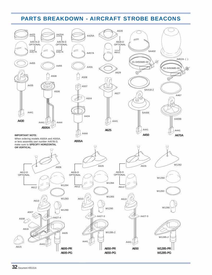
Document #05131A32
SA402
01-0450685-00
SA418-2
SA406
A441
A402A- ( )
A467
A469B
A441
A425
A457A-DOPTIONAL
A457A
A455
A435
A441
A425A
A457B-DOPTIONAL
A457A
A455
A506
A444
A508
A441
A425A
A457A
A455
A507
A424
A508
A504
A444
A628
A612
A629
A627
A441
A628-DOPTIONAL
A441
A606
A612-DOPTIONAL
A612W1284
A616
A441
W1283A610
W1290A507
A427-4A508
A615
A605
A626
A626-DOPTIONAL
A612
W1284
A610
A441
W1283A610
W1290
A612
A427-3
W1282
A427-3
W1285-2
A626-DOPTIONAL
A626
W1284
W1283
W1290
W1285-2
01-0450685-00
A600-PRA600-PG
A650-PRA650-PG
A650 W1285-PRW1285-PG
A430
A500A
A555A
A625A450 A470AIMPORTANT NOTE:
When ordering models A500A and A555A,or lens assembly part number A457B-D, make sure to SPECIFY HORIZONTALOR VERTICAL.
PARTS BREAKDOWN - AIRCRAFT STROBE BEACONS

APPENDIX A
© 2007 Whelen Engineering Company, Inc. Document #05131A 33

Document #05131A34

© 2007 Whelen Engineering Company, Inc. Document #05131A 35
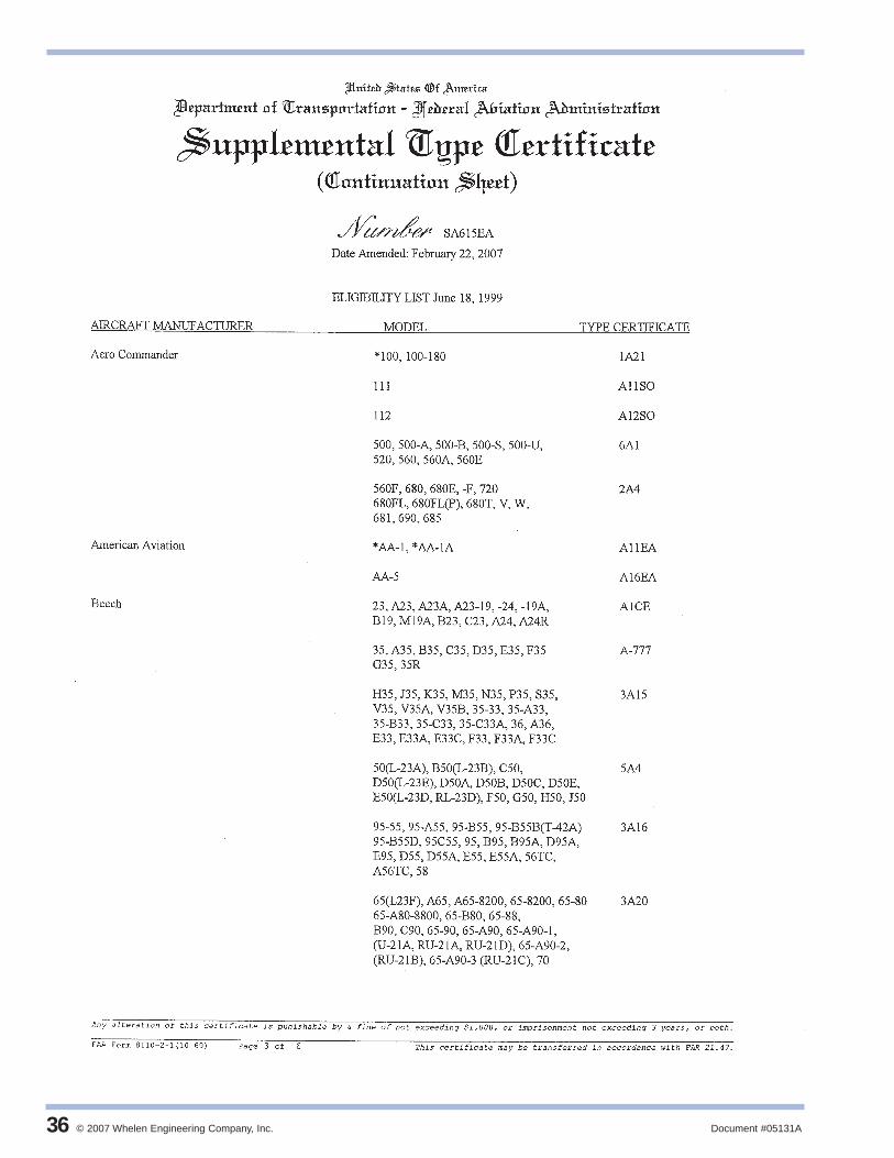
© 2007 Whelen Engineering Company, Inc. Document #05131A36

Document #05131A 37
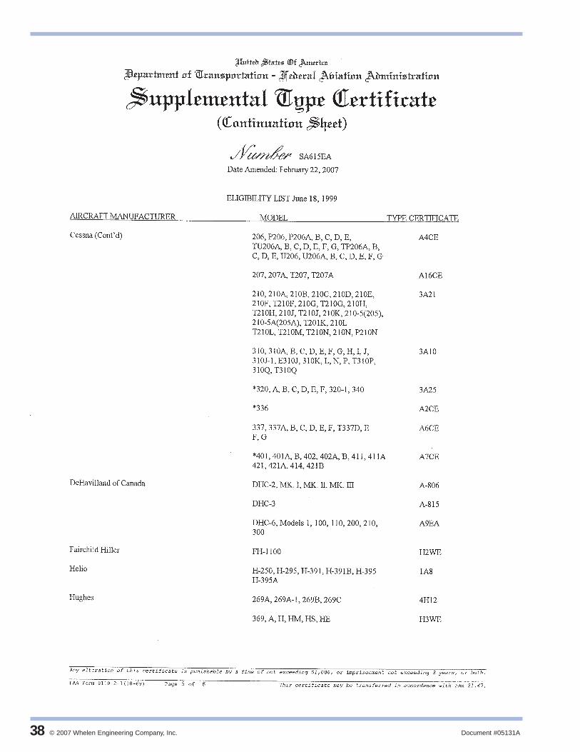
© 2007 Whelen Engineering Company, Inc. Document #05131A38

Document #05131A 39

© 2007 Whelen Engineering Company, Inc. Document #05131A40

Document #05131A 41
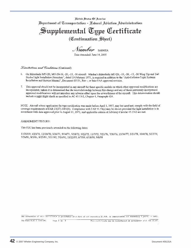
© 2007 Whelen Engineering Company, Inc. Document #05131A42

Document #05131A 43

© 2007 Whelen Engineering Company, Inc. Document #05131A44

Document #05131A 45

© 2007 Whelen Engineering Company, Inc. Document #05131A46

Document #05131A 47

© 2007 Whelen Engineering Company, Inc. Document #05131A48
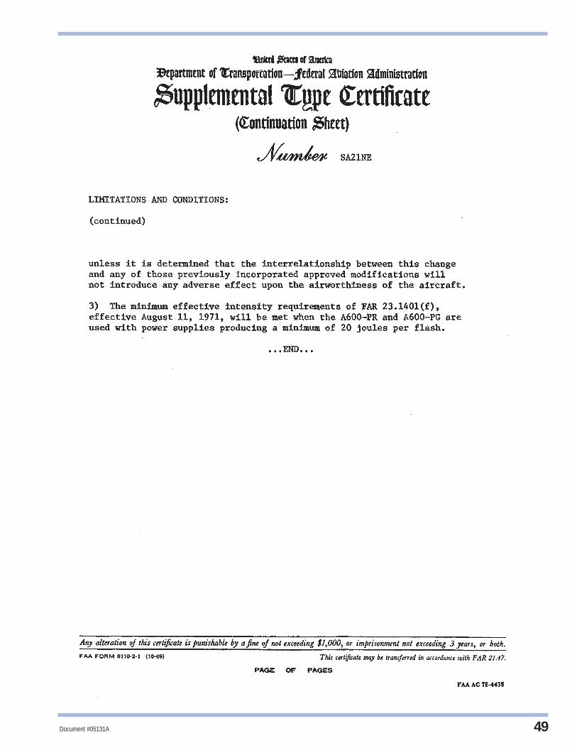
Document #05131A 49

Document #05131A50
NOTES

© 2007 Whelen Engineering Company, Inc. Document #05131A 51
®
The Latest Technology in Strobe and LED Aviation Lighting!
Visit us on the web at
www.whelen.com
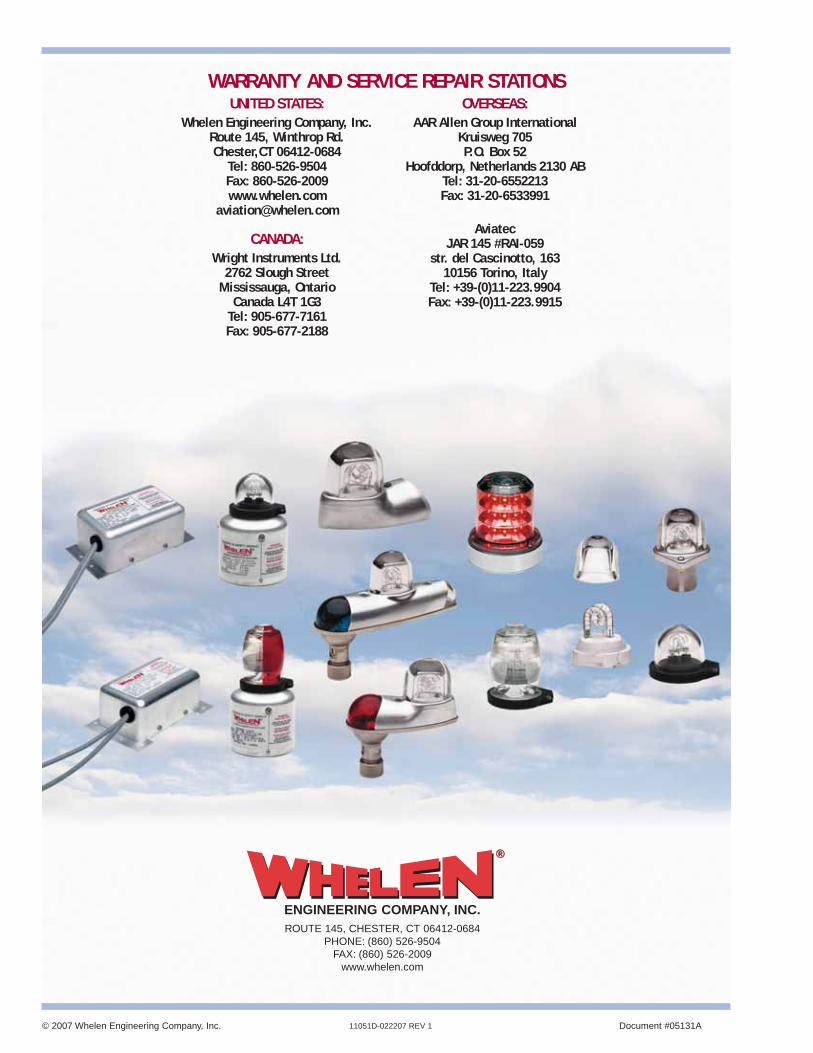
© 2007 Whelen Engineering Company, Inc. Document #05131A11051D-022207 REV 1
ROUTE 145, CHESTER, CT 06412-0684PHONE: (860) 526-9504
FAX: (860) 526-2009www.whelen.com
®®
ENGINEERING COMPANY, INC.
WARRANTY AND SERVICE REPAIR STATIONSUNITED STATES:
Whelen Engineering Company, Inc.Route 145, Winthrop Rd.Chester,CT 06412-0684
Tel: 860-526-9504Fax: 860-526-2009www.whelen.com
CANADA:Wright Instruments Ltd.
2762 Slough StreetMississauga, Ontario
Canada L4T 1G3Tel: 905-677-7161Fax: 905-677-2188
OVERSEAS:AAR Allen Group International
Kruisweg 705P.O. Box 52
Hoofddorp, Netherlands 2130 ABTel: 31-20-6552213Fax: 31-20-6533991
AviatecJAR 145 #RAI-059
str. del Cascinotto, 16310156 Torino, Italy
Tel: +39-(0)11-223.9904Fax: +39-(0)11-223.9915