antonio sanchez's rotary engine 2013.pdf
DESCRIPTION
A four-stroke engine extremely compact (1960 cc displacement in a cylinder of 36 cm. diameter and 16 cm. height) , efficient, absolutely rotary, valveless, and with very simple configuration, that have adequate lubrication and cooling systems. Sparkplug operation angle and / or injector is wide and almost similar to reciprocating engine (23% of the compression stroke), ie it is possible to advance the ignition or injection. The piston at TDC reaches its minimum rotational speed, very close to the arrest,thus avoiding misfiring. Lubricant is projected onto all internal parts, then beswept, drained, cooled and returned to project continuously, ensuring not onlythe full lubrication, but thermal stability in all parts.TRANSCRIPT

1
Antonio Sánchez Rotary Engine 2.013S. Pat. n. P201330865
Author:Antonio Sánchez Vargas
Málaga. España
e-mail: [email protected]
Antonio Sánchez's 2.013 Rotary Engine. Pat. P201330865
2
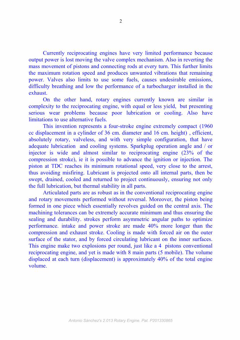
Currently reciprocating engines have very limited performance because output power is lost moving the valve complex mechanism. Also in reverting the mass movement of pistons and connecting rods at every turn. This further limits the maximum rotation speed and produces unwanted vibrations that remaining power. Valves also limits to use some fuels, causes undesirable emissions, difficulty breathing and low the performance of a turbocharger installed in the exhaust.
On the other hand, rotary engines currently known are similar in complexity to the reciprocating engine, with equal or less yield, but presenting serious wear problems because poor lubrication or cooling. Also have limitations to use alternative fuels.
This invention represents a four-stroke engine extremely compact (1960 cc displacement in a cylinder of 36 cm. diameter and 16 cm. height) , efficient, absolutely rotary, valveless, and with very simple configuration, that have adequate lubrication and cooling systems. Sparkplug operation angle and / or injector is wide and almost similar to reciprocating engine (23% of the compression stroke), ie it is possible to advance the ignition or injection. The piston at TDC reaches its minimum rotational speed, very close to the arrest, thus avoiding misfiring. Lubricant is projected onto all internal parts, then be swept, drained, cooled and returned to project continuously, ensuring not only the full lubrication, but thermal stability in all parts.
Articulated parts are as robust as in the conventional reciprocating engine and rotary movements performed without reversal. Moreover, the piston being formed in one piece which essentially revolves guided on the central axis. The machining tolerances can be extremely accurate minimum and thus ensuring the sealing and durability. strokes perform asymmetric angular paths to optimize performance. intake and power stroke are made 40% more longer than the compression and exhaust stroke. Cooling is made with forced air on the outer surface of the stator, and by forced circulating lubricant on the inner surfaces. This engine make two explosions per round, just like a 4 pistons conventional reciprocating engine, and yet is made with 8 main parts (5 mobile). The volume displaced at each turn (displacement) is approximately 40% of the total engine volume.
Antonio Sánchez's 2.013 Rotary Engine. Pat. P201330865
3
DESCRIPTION
Antonio Sánchez's 2.013 Rotary Engine. Pat. P201330865

4
This invention relates to a new internal combustion engine prototype, whose
moving parts made only rotary movements without arresting or reversing masses.
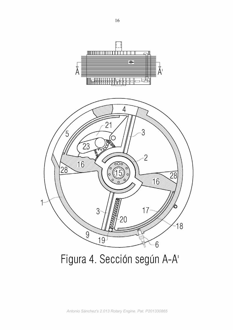
This engine is made of steel, and as show in the figures, consists of a stator (1), that
is a cylindrical cavity that housing a rotor (2) with two rotary pistons (3), merged these
in one single piece. The stator has an intake window (4) and an exhaust window (5).
It also has a sparkplug (6) located diametrically opposite to the windows and on the
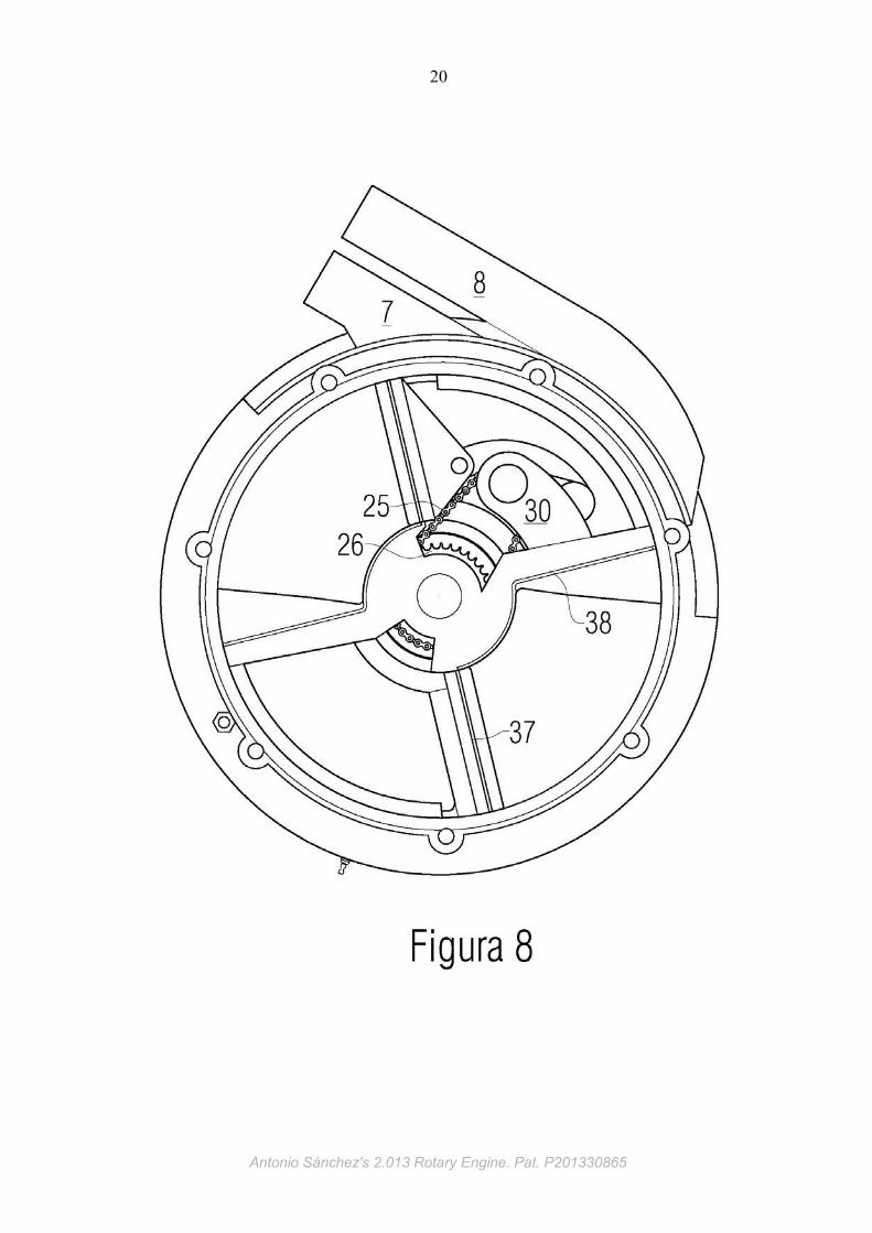
same plane. The inlet and exhaust windows extend outward in the intake manifold (7)
and exhaust manifold (8) respectively. On its outer surface, the stator is formed with a
plurality of cooling fins horizontal and vertical (9). As part of the lubrication system,
stator cover have drilled in the center a plurality of drain windows (10) and an external
drain channel (11) on its periphery, as shown in Figure 11. This channel collects the
lubricant that is centrifugate by the rotor into the inner cylindrical walls of the stator,
which then decanted by gravity, leading to the lubricant pump (12). The engine is
closed by the stator cover (13), also formed externally with a plurality of cooling fins,
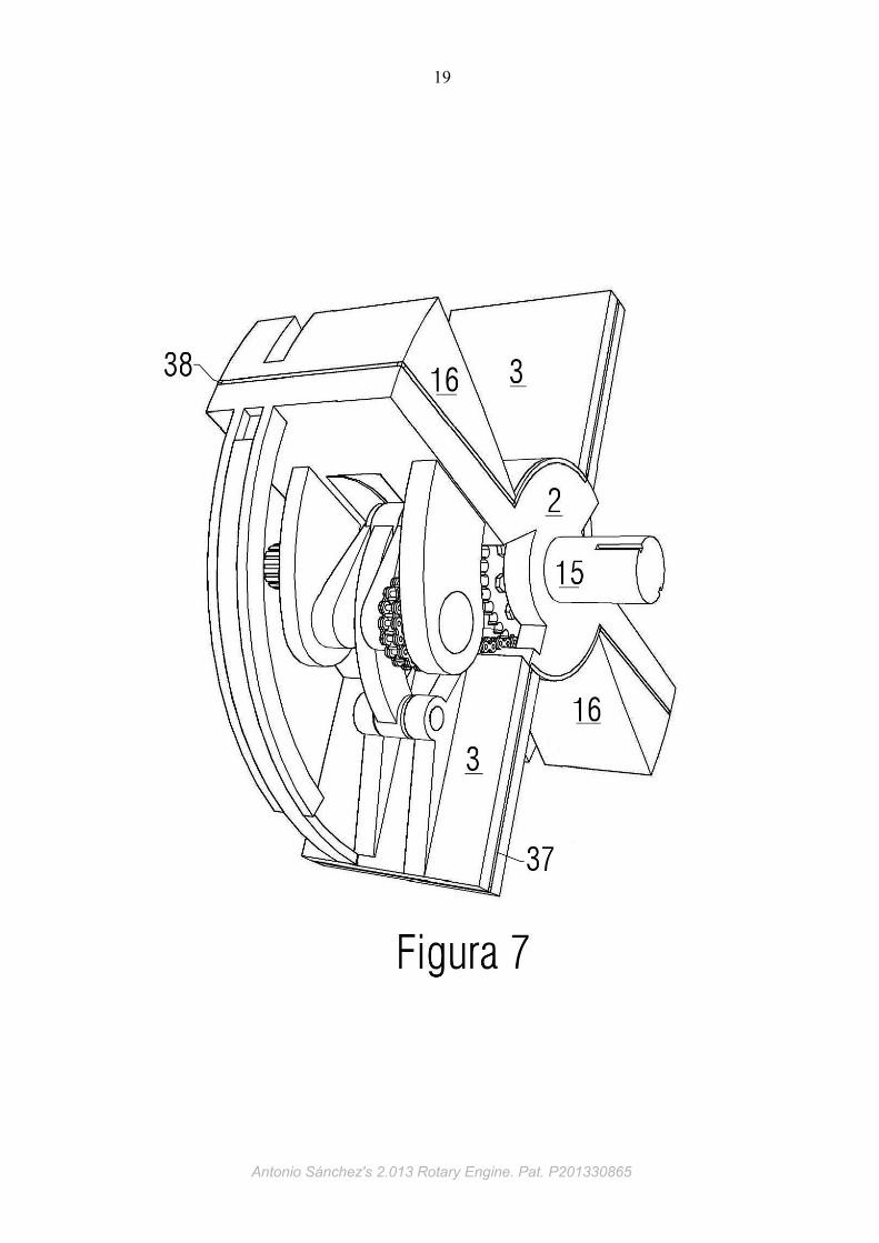
This cover is fastened and tied on the stator with screws (14). The rotor, seen from
the lubricant pump, rotates counter-clockwise, and is comprised with a main shaft
(15) and two heads (16). Each head is extended on its posterior surface, in a sealing
bow (17). Each head bow overlaps with a bow seal of the piston (18) located behind,
in the direction of rotation. These arcs are located on the same plane as the windows
and the sparkplug, and its function is waterproof them lubricant and prevent leakage
thereof. The pistons rotate in the same direction of the rotor, and are shaped as
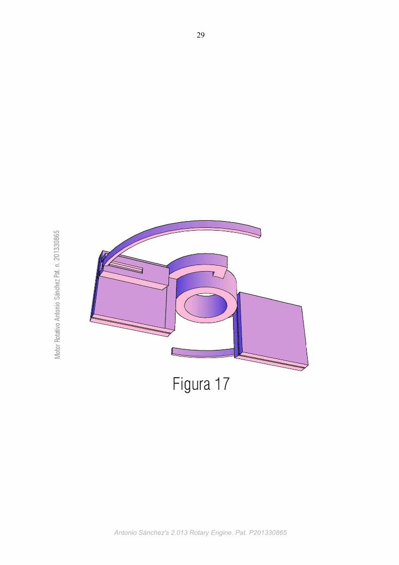
cylindrical ring segment, moving precisely fitted between the stator and rotor. At the
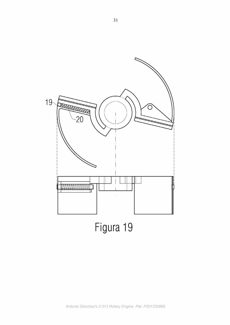
rear, one of the pistons has a roller (19) that remaining permanently applied against
the inner cylindrical surface of the stator by its spring (20). The roller rotates on its
axis when rotates the piston, and collects lubricant and printing them on the inner
cylindrical surface of the stator which is covered by sealing bows. On the back, the
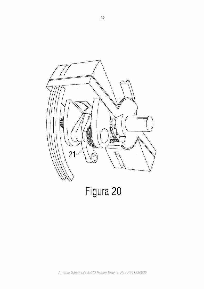
other piston is connected to the bottom of the connecting rod (21) through a
cylindrical pin (22). This connecting rod is connected at its head to the crankshaft
(23). In this way forms a hinged joint mechanism for converting the reciprocating
circular motion of the pistons in a continuous circular motion on the crankshaft and
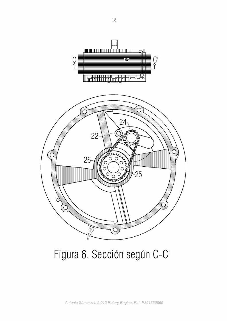
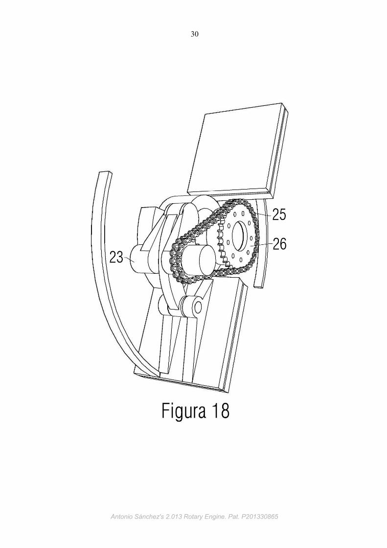
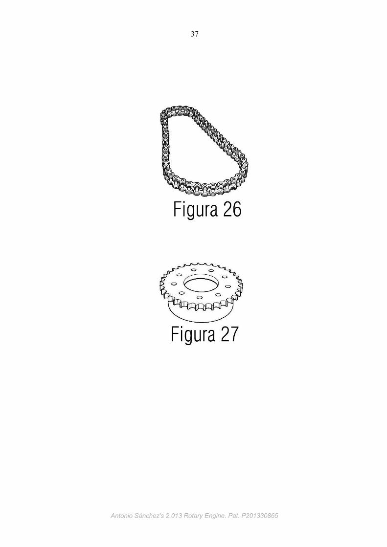
vice versa. The crankshaft has a sprocket (24) situated as expressed in Figure 24.
The crankshaft sprocket meshes with the chain link (25), which in turn is meshed to
the stator central sprocket (26) that's statics. These three pieces are placed on the
same plane. The static sprocket is twice the diameter and number of teeth relative to
Antonio Sánchez's 2.013 Rotary Engine. Pat. P201330865
5
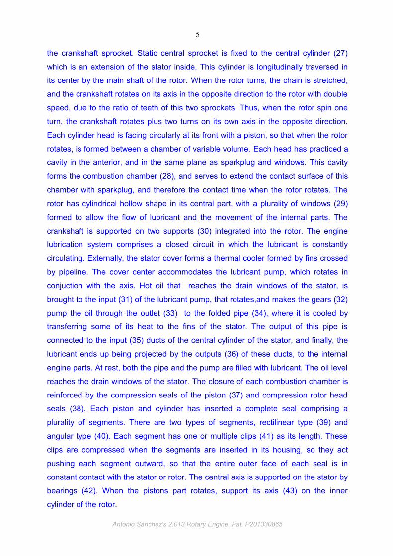
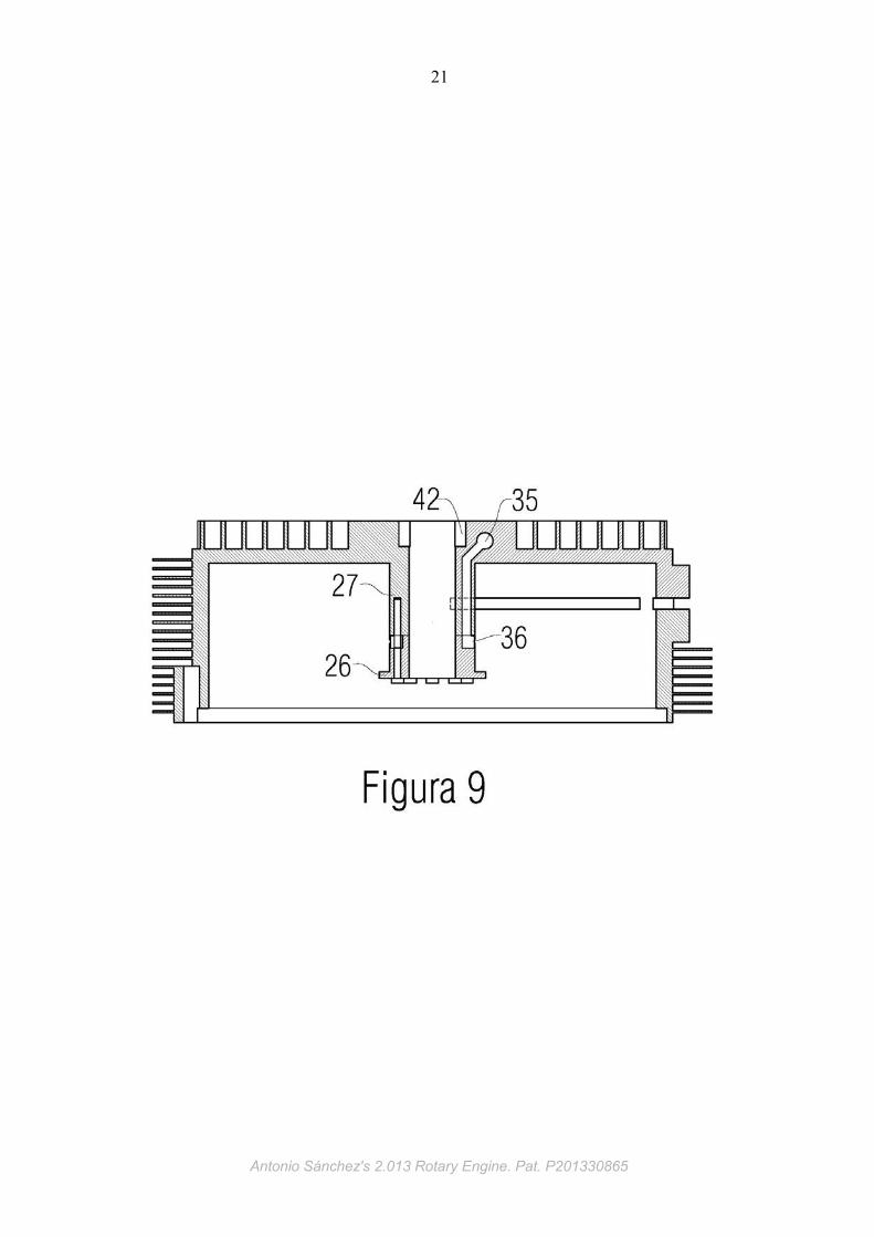
the crankshaft sprocket. Static central sprocket is fixed to the central cylinder (27)
which is an extension of the stator inside. This cylinder is longitudinally traversed in
its center by the main shaft of the rotor. When the rotor turns, the chain is stretched,
and the crankshaft rotates on its axis in the opposite direction to the rotor with double
speed, due to the ratio of teeth of this two sprockets. Thus, when the rotor spin one
turn, the crankshaft rotates plus two turns on its own axis in the opposite direction.
Each cylinder head is facing circularly at its front with a piston, so that when the rotor
rotates, is formed between a chamber of variable volume. Each head has practiced a
cavity in the anterior, and in the same plane as sparkplug and windows. This cavity
forms the combustion chamber (28), and serves to extend the contact surface of this
chamber with sparkplug, and therefore the contact time when the rotor rotates. The
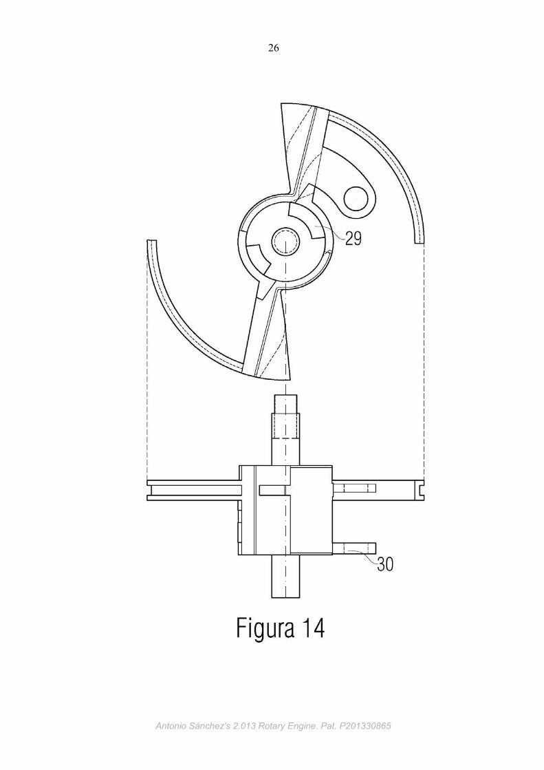
rotor has cylindrical hollow shape in its central part, with a plurality of windows (29)
formed to allow the flow of lubricant and the movement of the internal parts. The
crankshaft is supported on two supports (30) integrated into the rotor. The engine
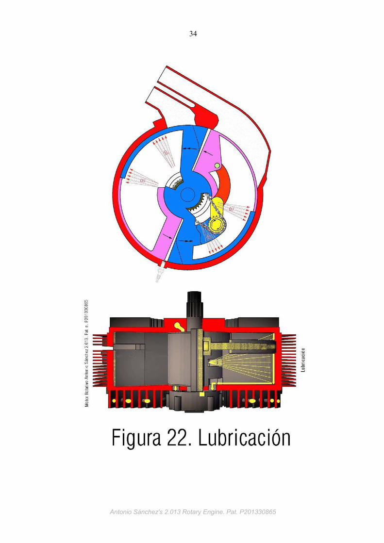
lubrication system comprises a closed circuit in which the lubricant is constantly
circulating. Externally, the stator cover forms a thermal cooler formed by fins crossed
by pipeline. The cover center accommodates the lubricant pump, which rotates in
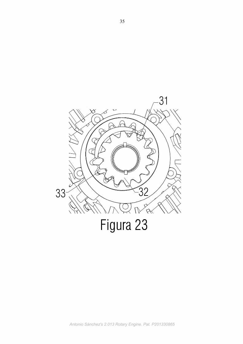
conjuction with the axis. Hot oil that reaches the drain windows of the stator, is
brought to the input (31) of the lubricant pump, that rotates,and makes the gears (32)
pump the oil through the outlet (33) to the folded pipe (34), where it is cooled by
transferring some of its heat to the fins of the stator. The output of this pipe is
connected to the input (35) ducts of the central cylinder of the stator, and finally, the
lubricant ends up being projected by the outputs (36) of these ducts, to the internal
engine parts. At rest, both the pipe and the pump are filled with lubricant. The oil level
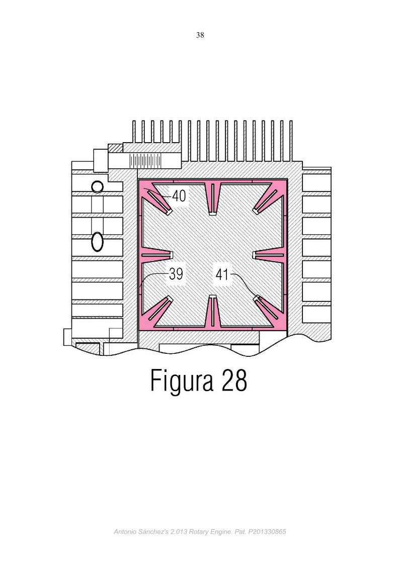
reaches the drain windows of the stator. The closure of each combustion chamber is
reinforced by the compression seals of the piston (37) and compression rotor head
seals (38). Each piston and cylinder has inserted a complete seal comprising a
plurality of segments. There are two types of segments, rectilinear type (39) and
angular type (40). Each segment has one or multiple clips (41) as its length. These
clips are compressed when the segments are inserted in its housing, so they act
pushing each segment outward, so that the entire outer face of each seal is in
constant contact with the stator or rotor. The central axis is supported on the stator by
bearings (42). When the pistons part rotates, support its axis (43) on the inner
cylinder of the rotor.
Antonio Sánchez's 2.013 Rotary Engine. Pat. P201330865
6
Antonio Sánchez's 2.013 Rotary Engine. Pat. P201330865
7
OPERATION
Antonio Sánchez's 2.013 Rotary Engine. Pat. P201330865
8
Engine operation shown in Figures 29 to 32. When the rotor rotates one turn,
the crankshaft rotates the same turn together with the rotor, but also rotates two turns
counterclockwise on its own axis. At each complete turn of the crankshaft about its
own axis, two strokes are developed in each piston, one of acceleration, and another
of deceleration in relation to the rotor. This causes each piston toward and away from
its rotor head pair alternately, thus varying the volume between the two.
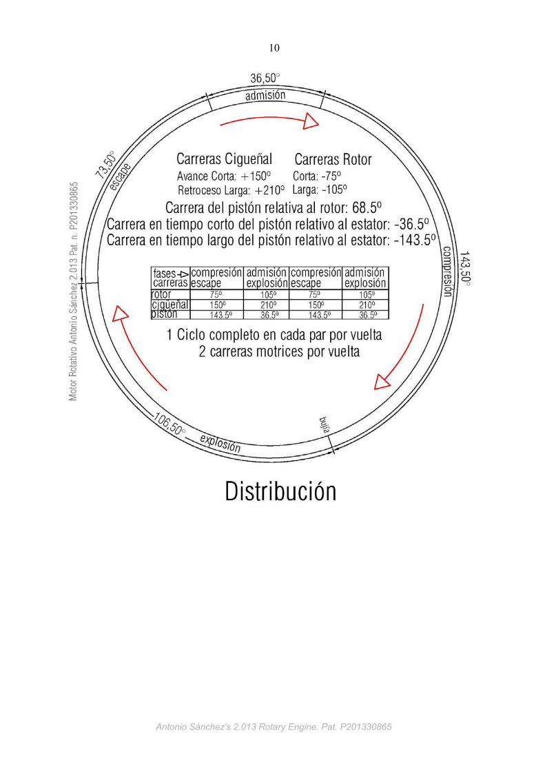
These strokes develop different angular paths, both piston, and rotor and crankshaft.
In acceleration stroke, the piston rotates on the stator 143.5°, and in the deceleration
stroke, 36.5° on the stator. At the same time, rotor rotates 75° in the acceleration
stroke of the pistón and 105º in deceleration stroke. The rotational speed of the
crankshaft about its axis is doubled relative to the rotor on the stator, but in the
opposite direction. Ie in the stroke acceleration the crankshaft rotates 150° and in
deceleration stroke 210º. This engine operates in the conventional four stroke cycle,
so that each piston travels a full rotation on the stator, developing four strokes. The
intake stroke during 36.5 º path, the compression during 143.5°, the explosion 36.5º,
and the exhaust for 143.5º. The sum of the four strokes totalizes the 360 ° full circle.
The rotor rotates at uniform speed, while the piston alternating accelerations followed
by decelerations. Figure 29 represents the start of intake stroke in a piston-head pair.
At this time the rotor rotates 105°. Then, the rotor head is spinning with the rotor,
while the piston is decelerating, developing his stroke away from the rotor head. This
causes vacuum between them. At the beginning of stroke, the rotor head open the
intake window. In this window sucks air-fuel mixture that will fill the space that opens
up between piston and rotor head. The intake stroke ends when the piston
deceleration ends his stroke and reaches its point of maximum distance from the
rotor head.
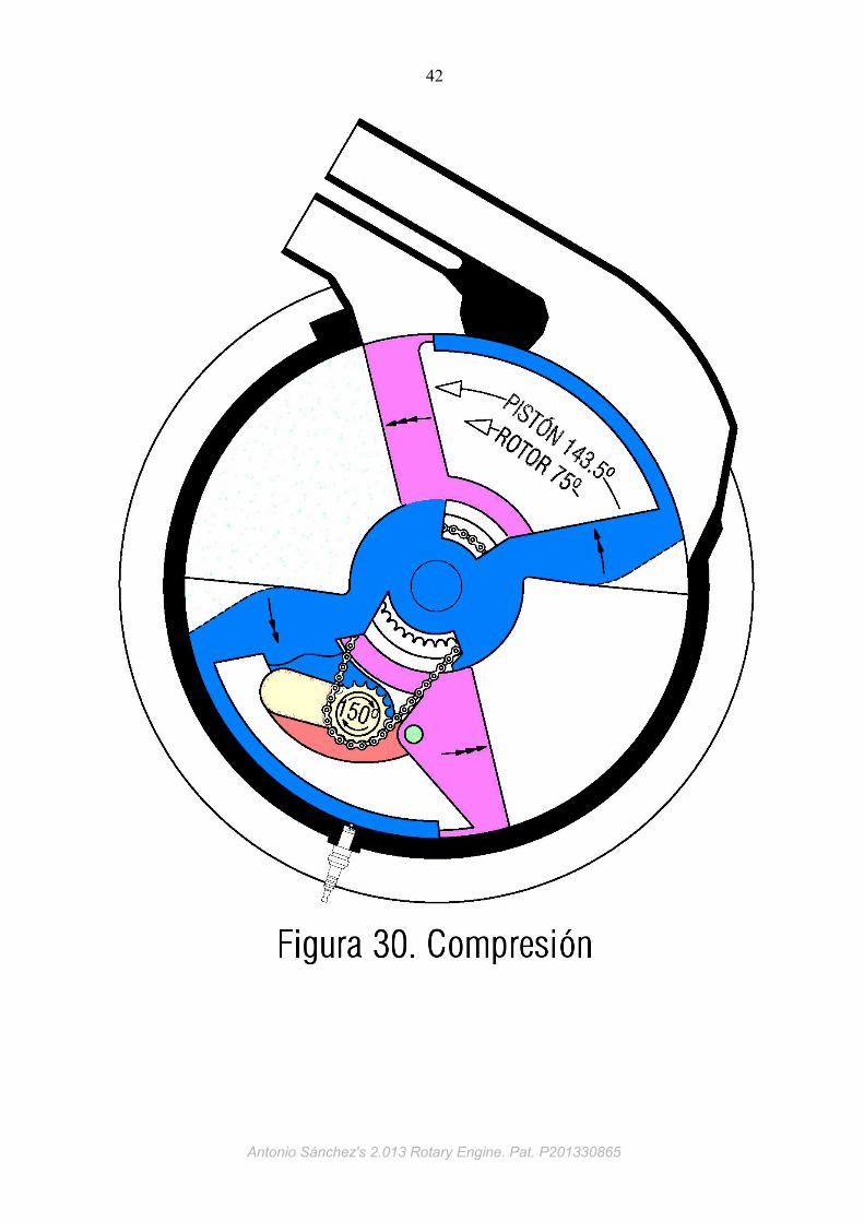
At this point begins the compression stroke in the same piston-head pair, that shown
in Figure 30. At this stroke the rotor turns 79°. The piston, driven by the connecting
rod, began his acceleration stroke (relative to the rotor head). Then, the piston
covers the intake window and begins to compress and heat the mixture previously
sucked. Near the end of the compression stroke, the combustion chamber of the
cylinder head contact with the sparkplug that is discovered by the head advance, and
simultaneously an electric spark jumps between the sparkplug electrodes, which
causes inflammation of the combustible mixture now compressed. Then ending the
compression stroke.
Antonio Sánchez's 2.013 Rotary Engine. Pat. P201330865
9
When the piston reaches again its point of minimum distance from the head
pair, starts the power stroke, that shown in Figure 31. At this stroke, the rotor rotates
105º. The piston then begins its deceleration stroke driven by the pressure exerted by
the combustion, which presses accelerating the rotor head and decelerating the
piston. This is the power stroke. The piston receives the thrust of the explosion, which
is converted into positive thrust on the rotor and output shaft through conversion by
the crankshaft sprocket with the drive chain and central fixed sprocket.
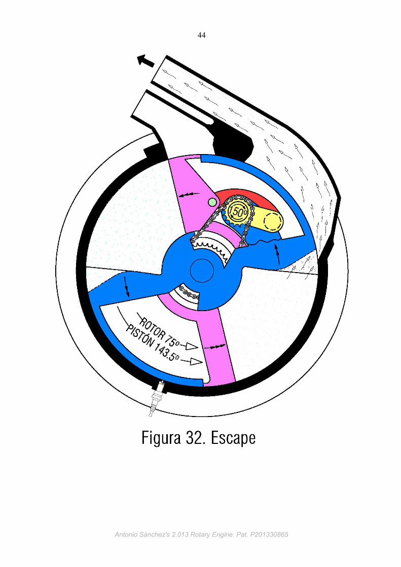
Near the end of the power stroke, the rotor head (combustion chamber) open
the exhaust window. Then pressurized gases contained between the piston and the
rotor head escape through this exhaust window to the exhaust duct outside. Once the
power stroke ends, when piston and head reaches its maximum distance again,
begins the exhaust stroke that shown in Figure 32. At this time the rotor turns 75°.
Then the piston starts again an acceleration stroke, approaching the rotor head. As
the exhaust window is constantly opened by the rotor head, the gases are expelled to
the exhaust conduit outside.
When this stroke ends and has completed the expulsion of gases, the piston
reaches its minimum distance from the head, and then starts a new intake stroke.
Thus, in the described manner, the rotor will rotate without interruption and
performing the four phases of operation in both enter the fuel and spark plug ignites
the mixture.
Antonio Sánchez's 2.013 Rotary Engine. Pat. P201330865
10
Antonio Sánchez's 2.013 Rotary Engine. Pat. P201330865

11
FIGURES
Antonio Sánchez's 2.013 Rotary Engine. Pat. P201330865
12
Description of the Figures
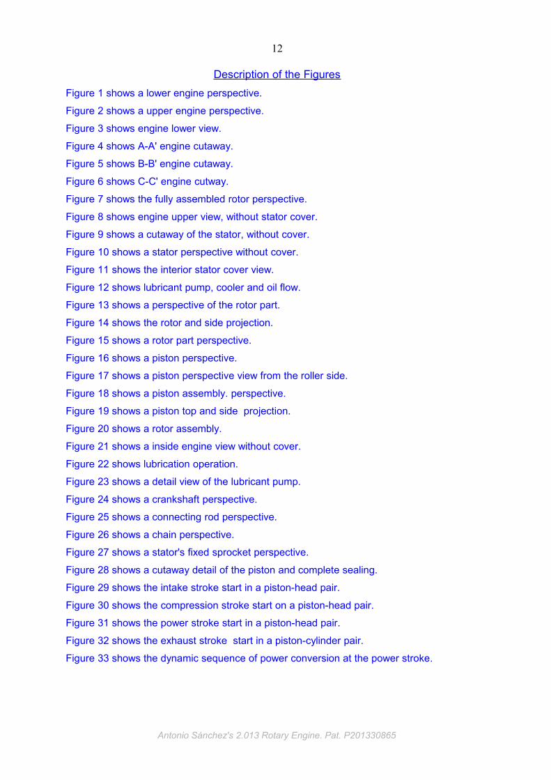
Figure 1 shows a lower engine perspective.
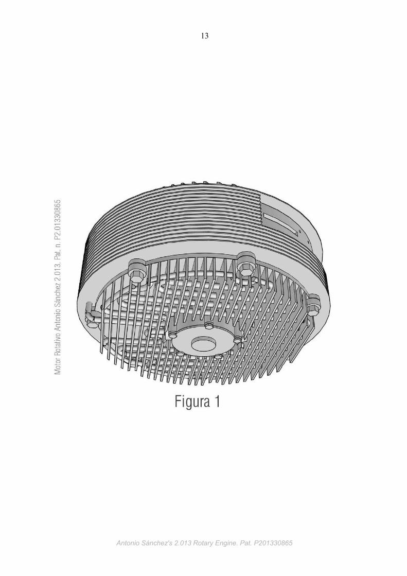
Figure 2 shows a upper engine perspective.
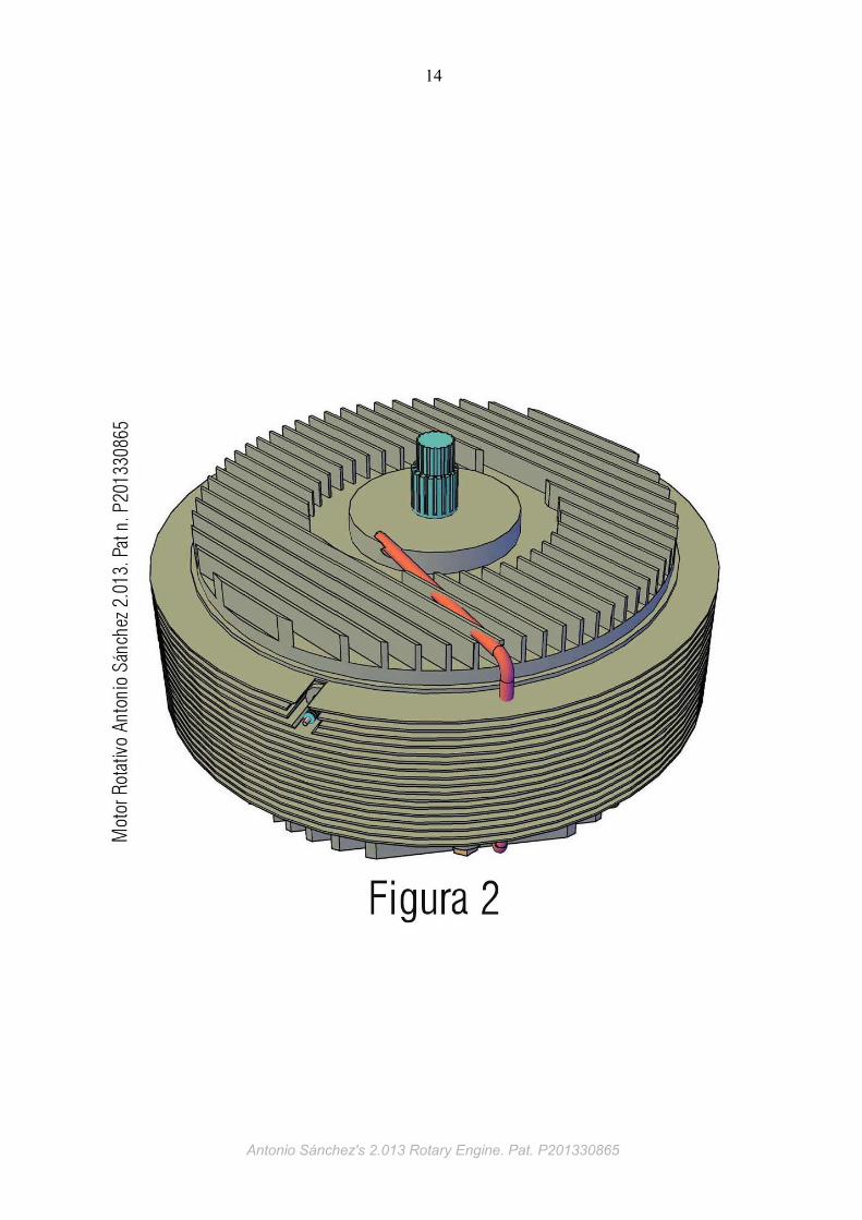
Figure 3 shows engine lower view.
Figure 4 shows A-A' engine cutaway.
Figure 5 shows B-B' engine cutaway.
Figure 6 shows C-C' engine cutway.
Figure 7 shows the fully assembled rotor perspective.
Figure 8 shows engine upper view, without stator cover.
Figure 9 shows a cutaway of the stator, without cover.
Figure 10 shows a stator perspective without cover.
Figure 11 shows the interior stator cover view.
Figure 12 shows lubricant pump, cooler and oil flow.
Figure 13 shows a perspective of the rotor part.
Figure 14 shows the rotor and side projection.
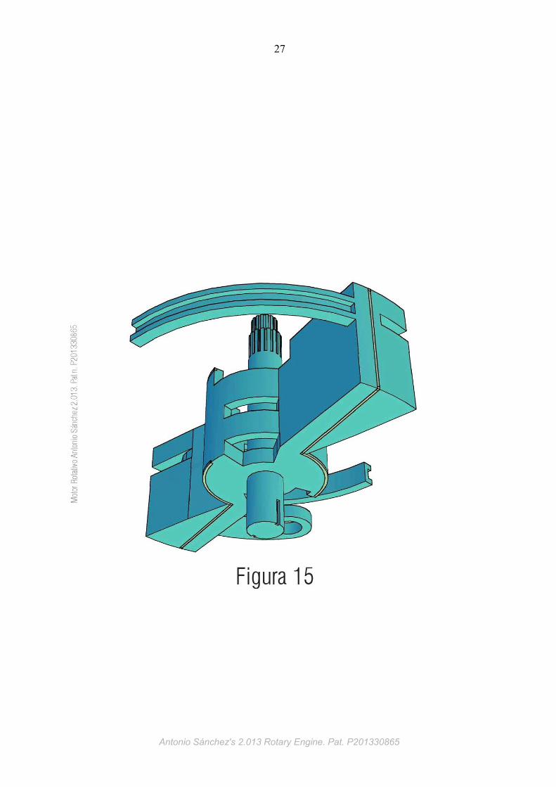
Figure 15 shows a rotor part perspective.
Figure 16 shows a piston perspective.
Figure 17 shows a piston perspective view from the roller side.
Figure 18 shows a piston assembly. perspective.
Figure 19 shows a piston top and side projection.
Figure 20 shows a rotor assembly.
Figure 21 shows a inside engine view without cover.
Figure 22 shows lubrication operation.
Figure 23 shows a detail view of the lubricant pump.
Figure 24 shows a crankshaft perspective.
Figure 25 shows a connecting rod perspective.
Figure 26 shows a chain perspective.
Figure 27 shows a stator's fixed sprocket perspective.
Figure 28 shows a cutaway detail of the piston and complete sealing.
Figure 29 shows the intake stroke start in a piston-head pair.
Figure 30 shows the compression stroke start on a piston-head pair.
Figure 31 shows the power stroke start in a piston-head pair.
Figure 32 shows the exhaust stroke start in a piston-cylinder pair.
Figure 33 shows the dynamic sequence of power conversion at the power stroke.
Antonio Sánchez's 2.013 Rotary Engine. Pat. P201330865
13
Antonio Sánchez's 2.013 Rotary Engine. Pat. P201330865
14
Antonio Sánchez's 2.013 Rotary Engine. Pat. P201330865
15
Antonio Sánchez's 2.013 Rotary Engine. Pat. P201330865
16
Antonio Sánchez's 2.013 Rotary Engine. Pat. P201330865

17
Antonio Sánchez's 2.013 Rotary Engine. Pat. P201330865
18
Antonio Sánchez's 2.013 Rotary Engine. Pat. P201330865
19
Antonio Sánchez's 2.013 Rotary Engine. Pat. P201330865
20
Antonio Sánchez's 2.013 Rotary Engine. Pat. P201330865
21
Antonio Sánchez's 2.013 Rotary Engine. Pat. P201330865

22
Antonio Sánchez's 2.013 Rotary Engine. Pat. P201330865

23
Antonio Sánchez's 2.013 Rotary Engine. Pat. P201330865

24
Antonio Sánchez's 2.013 Rotary Engine. Pat. P201330865

25
Antonio Sánchez's 2.013 Rotary Engine. Pat. P201330865
26
Antonio Sánchez's 2.013 Rotary Engine. Pat. P201330865
27
Antonio Sánchez's 2.013 Rotary Engine. Pat. P201330865

28
Antonio Sánchez's 2.013 Rotary Engine. Pat. P201330865
29
Antonio Sánchez's 2.013 Rotary Engine. Pat. P201330865
30
Antonio Sánchez's 2.013 Rotary Engine. Pat. P201330865
31
Antonio Sánchez's 2.013 Rotary Engine. Pat. P201330865
32
Antonio Sánchez's 2.013 Rotary Engine. Pat. P201330865

33
Antonio Sánchez's 2.013 Rotary Engine. Pat. P201330865
34
Antonio Sánchez's 2.013 Rotary Engine. Pat. P201330865
35
Antonio Sánchez's 2.013 Rotary Engine. Pat. P201330865

36
Antonio Sánchez's 2.013 Rotary Engine. Pat. P201330865
37
Antonio Sánchez's 2.013 Rotary Engine. Pat. P201330865
38
Antonio Sánchez's 2.013 Rotary Engine. Pat. P201330865
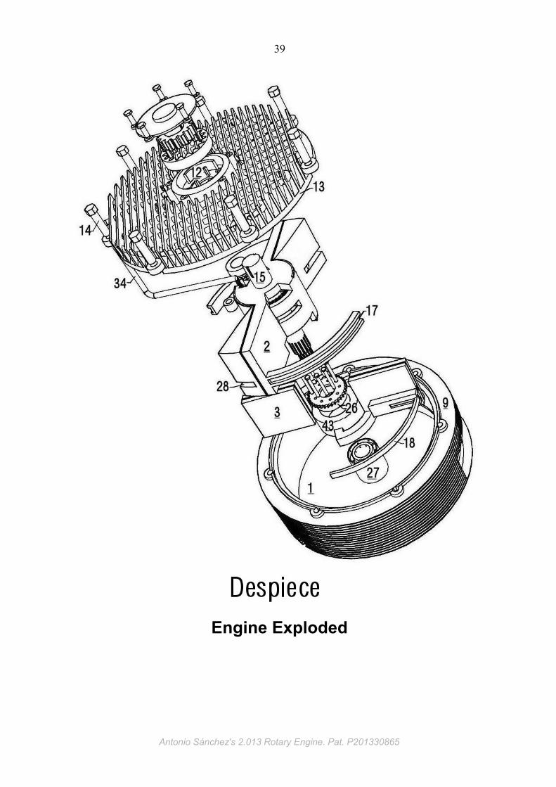
39
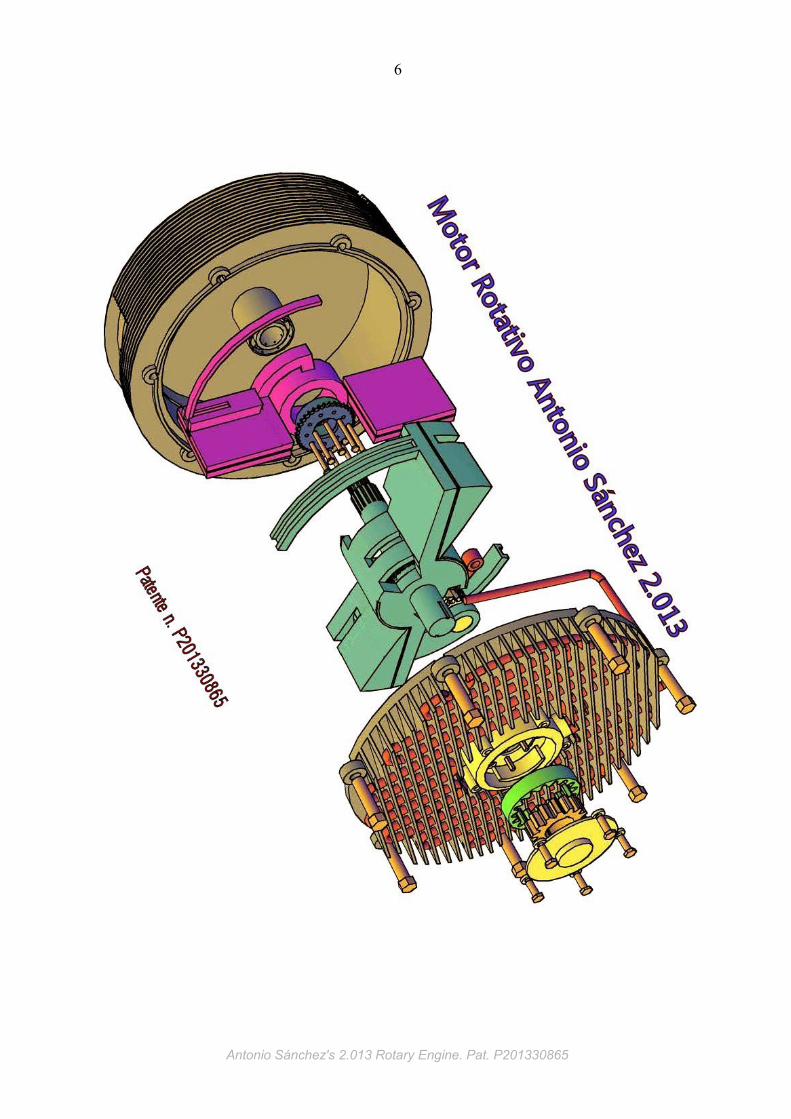
Engine Exploded
Antonio Sánchez's 2.013 Rotary Engine. Pat. P201330865
40
OPERATION
Antonio Sánchez's 2.013 Rotary Engine. Pat. P201330865

41
Antonio Sánchez's 2.013 Rotary Engine. Pat. P201330865
42
Antonio Sánchez's 2.013 Rotary Engine. Pat. P201330865

43
Antonio Sánchez's 2.013 Rotary Engine. Pat. P201330865
44
Antonio Sánchez's 2.013 Rotary Engine. Pat. P201330865

45
Antonio Sánchez's 2.013 Rotary Engine. Pat. P201330865
46
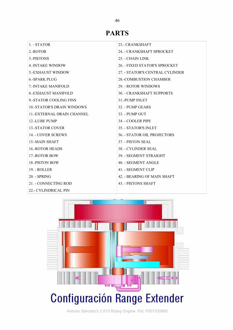
PARTS
1. - STATOR
2.-ROTOR
3.-PISTONS
4.-INTAKE WINDOW
5.-EXHAUST WINDOW
6.-SPARK PLUG
7.-INTAKE MANIFOLD
8.-EXHAUST MANIFOLD
9.-STATOR COOLING FINS
10.-STATOR'S DRAIN WINDOWS
11.-EXTERNAL DRAIN CHANNEL
12.-LUBE PUMP
13.-STATOR COVER
14. - COVER SCREWS
15.-MAIN SHAFT
16.-ROTOR HEADS
17.-ROTOR BOW
18.-PISTON BOW
19. - ROLLER
20. - SPRING
21. - CONNECTING ROD
22.- CYLINDRICAL PIN
23.- CRANKSHAFT
24. - CRANKSHAFT SPROCKET
25. - CHAIN LINK
26. - FIXED STATOR'S SPROCKET
27. - STATOR'S CENTRAL CYLINDER
28.-COMBUSTION CHAMBER
29. - ROTOR WINDOWS
30. - CRANKSHAFT SUPPORTS
31.-PUMP INLET
32. - PUMP GEARS
33. - PUMP OUT
34. - COOLER PIPE
35. - STATOR'S INLET
36. - STATOR OIL PROJECTORS
37. - PISTON SEAL
38. - CYLINDER SEAL
39. - SEGMENT STRAIGHT
40. - SEGMENT ANGLE
41. - SEGMENT CLIP
42. - BEARING OF MAIN SHAFT
43. - PISTONS SHAFT
Antonio Sánchez's 2.013 Rotary Engine. Pat. P201330865
47
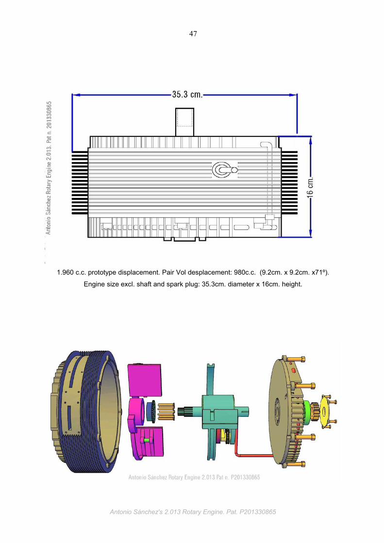
1.960 c.c. prototype displacement. Pair Vol desplacement: 980c.c. (9.2cm. x 9.2cm. x71º).
Engine size excl. shaft and spark plug: 35.3cm. diameter x 16cm. height.
Antonio Sánchez's 2.013 Rotary Engine. Pat. P201330865