ants in the ocean: system design techniques for underwater sensing applications ryan kastner dept....
Post on 20-Dec-2015
213 views
TRANSCRIPT

Ants in the Ocean: System Design Techniques
for Underwater Sensing Applications
Ryan KastnerDept. of Electrical and Computer Engineering
University of California, Santa Barbara
Computer Engineering SeminarNorthwestern University
May 24, 2004

Ecological Research Programs
Santa Barbara Channel Long Term Ecological Research (SBC LTER)
Partnership for Interdisciplinary Studies of Coastal Oceans (PISCO)
Goals Focuses on understanding the nearshore ecosystems of the west coast Time/space variation of individual organisms, populations, and ecological
communities

Ecological Studies
Importance of land vs. ocean processes in giant kelp forests How do different nutrients effect ecosystem? How/when are nutrients delivered? Runoff during storms very important time
Rough conditions, high surf, undertow How to measure?
Quantify larval transport to nearshore habitats Red tide Conditions for larval transport - temperature, salinity, chemicals?
Marine management tools When/where to make protected zones? What is effect of environmental factors on marine life?

Enabling Ecological Research
Many studies done over limited time framesDrop sensors, sit on boatStorm comes, run out to boats and throw sensors into
water Alternatively, leave sensors unattended
Malfunction loses months of dataSensors get lost/stolen
Ideal situation - real-time, adaptive sampling techniques

CoastalNet
Temp/Depth Sensors
802.11AP
Conductivity Sensor
Acoustic Link Low Rate/FSK
Acoustic Link
Acoustic Modem/Array Signal Processor
Directional Antenna (“Pringles Can”)
802.11Access Point
To Internet
Wi/Fi Link up to 7 miles
OFDM/DS Acoustic Link

CoastalNet Challenges
Underwater communicationWater more complex medium than air - severe
multipath problems, doppler shifts and long latenciesCommercial modems ~2400 baud – fine for simple
sensors. What about higher data rates? Sensors
Variety of different types, sizes – video, salinity, pressure, temperature, …
System design issues - equip with batteries, antennas, waterproof

Applications
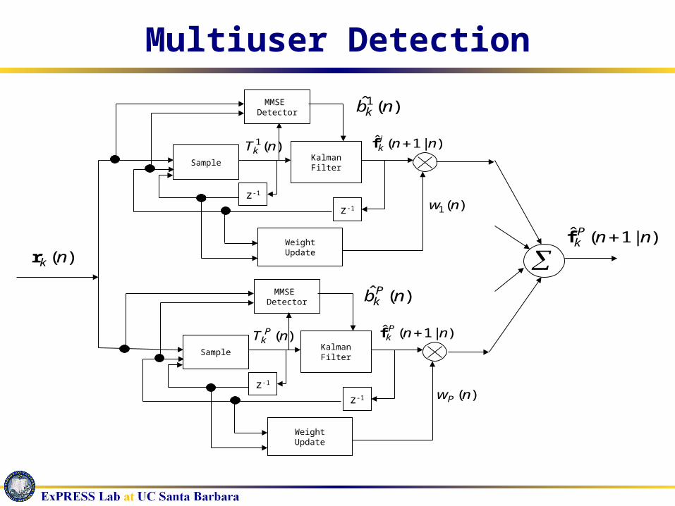
)(nkr )|1(ˆ nnP
k f
SampleKalmanFilter
z-1z-1
WeightUpdate
)(1 nw
)(1 nTk)|1(ˆ nni
k f
MMSE Detector
)(ˆ1 nbk
SampleKalmanFilter
z-1z-1
WeightUpdate
)(nwP
)(nT Pk
)|1(ˆ nnPk f
MMSE Detector
)(ˆ nb Pk
Multiuser Detection
EKF
skTc
v̂
skTc
v
ˆ1
sf kTc
vN
ˆ1
s
s
Nnc
v
nNc
vk
)1(ˆ
1
ˆ1
)(kr
bT
Re
..cc
)(nU
0̂f
1̂f
1ˆ
fNf
)ˆ( slp kTs
Underwater Acoustic Receivers
From A/D )1( s
j MNr )2( sj MNr )1(jr )0(jr
11 )( sMNbS
21 )( sMNbS
11 )( bS 01 )( bS
)(nr
1)( 1 js qMN
bS 21 1)( js qMN
bS121 )(
jqbS
111 )( jq
bS
1
ˆ
jqf
Address/Shift Left by qj-1-1
Multiply/Accumulate
r0(n)=r(n)
Signal Vector – Zero Shift
Signal Vector Shifted Left by qj-
1-1.
1)( blS 0)( b
lS1)( sMNblS 2)( sMN
blS
121 ,...,,,1by Left ift Address/Sh jqqqifori
iMNbl s )(S 1)( iMN
bl s
S ibl 2)(S
ibl 1)(S
2||||
1biS
if̂2
2|||| biS
jq
121 ,...,,
maxarg
jqqqi
1
ˆ
jqf 1
ˆ
jqf 1
ˆ
jqf
Radiolocation (GSIC)
Filters (FIR, ARF, EWF)

System Design Goal: Map application specification to system architecture
Subject to always increasing constraints – power, energy, latency, cost, size, …
© Sangiovanni-Vincentelli

System Design and Architecture Problem – take application code and map it to some system platform (e.g.
reconfigurable device) System platforms are extremely (and increasingly) complicated,
multiprocessing computing systems Mix of hardware and software components
Microprocessors – RISC, DSP, network, … Logic level (FPGA) Reconfigurable logic
Specs for current high performance FPGA (Xilinx Virtex II) 3K to 125K logic cells, Four PowerPC processor cores Complex memory hierarchy - 1,738 KB block RAM, external memory, local memory in
CLBs Possibility of soft core processors – DSP Custom hardware - embedded multipliers, fast carry chain logic, etc.
Large amount of performance improvement possible, IF there is a good mapping
How do we best represent the application for mapping?
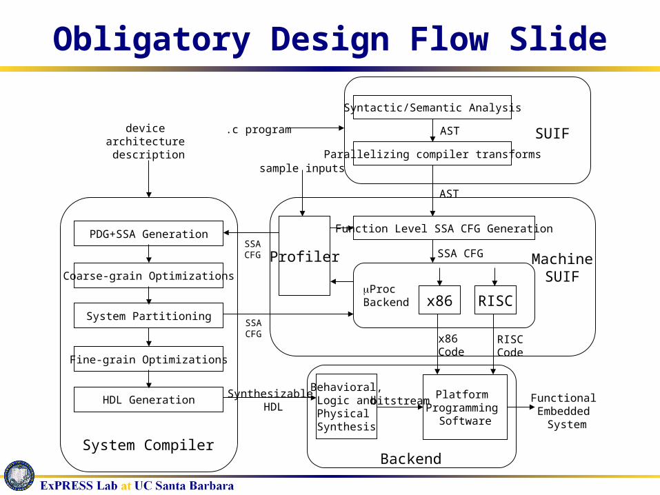
Obligatory Design Flow Slide
.c program
Syntactic/Semantic Analysis
AST
Parallelizing compiler transforms
SUIF
Function Level SSA CFG Generation
SSA CFG MachineSUIF
Proc Backend x86 RISC
x86 Code
RISCCode
Profiler
sample inputs
PDG+SSA Generation
Coarse-grain Optimizations
System Partitioning
HDL Generation
Fine-grain Optimizations
SSACFG
AST
device architecture description
System Compiler
Synthesizable HDL
Behavioral,Logic andPhysical Synthesis
Platform Programming
Software
bitstream Functional Embedded
System
Backend
SSACFG

Design Flow
Application specificationCan be written in C, SystemC, SystemVerilog, linear
systems, signal flow graph, CDFGsMust have front end to task graphsFocusing first on a C to task graph
Signal Flow Graph
if(x < y) i = 10;else i = 255;while(i) x = y++;
C code Linear Systems

Intermediate Representation
val = pred;
for(i = 0; i<len; i++)
val += diff;
if(val > 32767)
val = 32767;
else
if(val < -32768)
val = -32768;
Must exploit fine AND coarse-grain parallelism Ideally want automatic mapping Need a form that can do synthesis to both
hardware/software
?

PDG+SSA Representation
val = pred;
for(i = 0; i<len; i++)
val += diff;
if(val > 32767)
val = 32767;
else
if(val < -32768)
val = -32768;
Input Application (in C) CDFG Form

PDG+SSA Representation
CDFG Form PDG+SSA Form

Advantages of PDG+SSA Exploits parallelism
Explicitly shows control and data dependences Control structures do not limit data parallelism Regions are hyperblocks – allows aggressive optimizations
Synthesis to hardware and software
Looks complicated! What does it buy us?

Comparing CDFG, PDG
Benchmarks – bunch of MediaBench functions
PDG, CDFG 2-3 times faster than sequential execution PDG about 7% faster than CDFG PDG, CDFG approx. same area
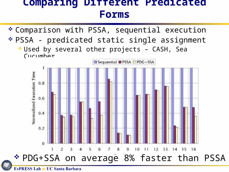
Comparing Different Predicated Forms
Comparison with PSSA, sequential execution PSSA - predicated static single assignment
Used by several other projects – CASH, Sea Cucumber
PDG+SSA on average 8% faster than PSSA

Map Application to HW/SW Cores
Dependence analysis to exploit fine/coarse grain parallelism Interprocedural dependencies –
selective inlining Control dependencies – loop
optimizations, hoisting, if conversion
Data dependencies – arrays, aliasing, liveness
System partitioning Cluster into coarser grained tasks Decide how to divide application
onto platform

System Partitioning
How do you decide where to map different parts of the application? Hardware or software – which processor, which memory, exact
location, etc. Extremely hard set of problems (NP-Hard)
Must be flexible - different applications/systems have wide variety of models
Fundamental problem - many different heuristic methods have been developed Simulated annealing Genetic Algorithms Tabu Search Kernighan/Lin …

Task Graph Model Application synthesis model Directed Acyclic Graph Each node is amount of computation
Coarse grained – loops, function calls, summations, filtering
Fine grained – addition, multiplication, comparison, shifting
System Partitioning Map coarse grain task nodes onto a set of
computational cores Cores – RISC processor, CLBs,
Digital Signal Processors, IPs, etc.
t1
t2 t3
t4 t5
t6
t7
t8
t0
tn

Our approach – Ant System Heuristic
Inspired by ethological study on the behavior of ants [Goss et. al. 1989]
A meta heuristic A multi-agent cooperative searching method A new way for combining global/local heuristics Extensible and flexible
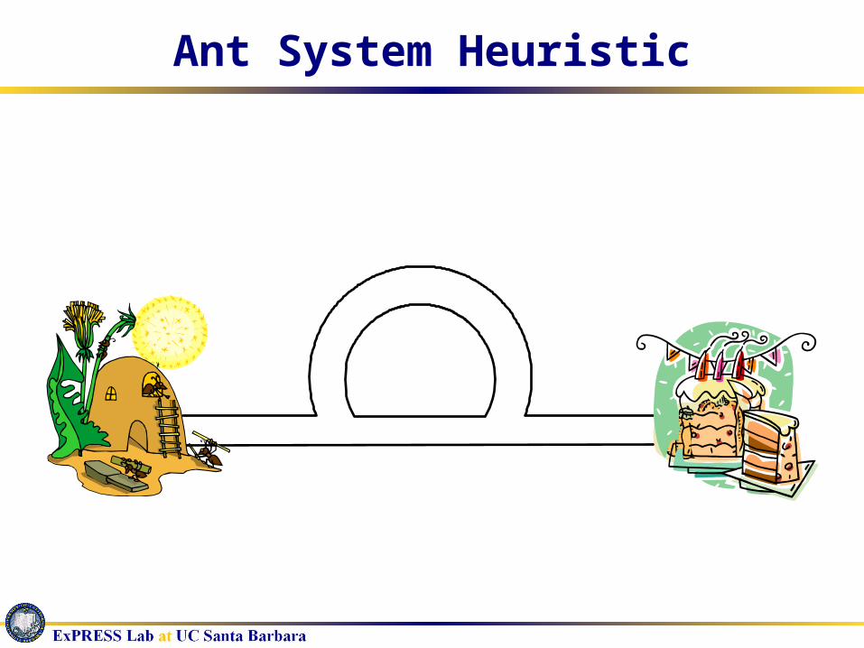
Ant System Heuristic
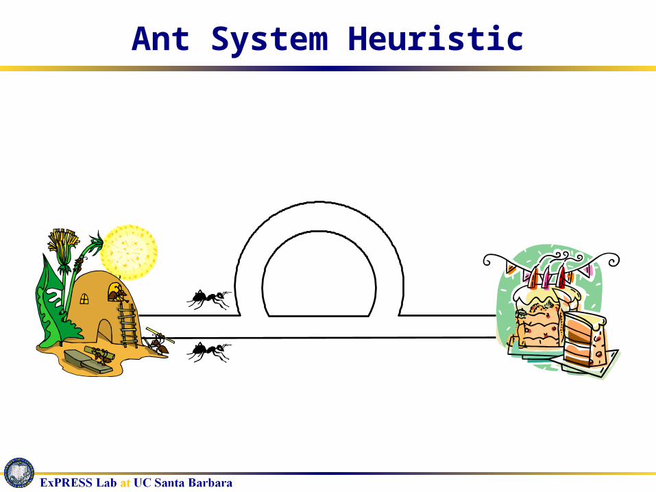
Ant System Heuristic

Ant System Heuristic

Ant System Heuristic

Ant System Heuristic

Ant System Heuristic

Ant System Heuristic

Ant System Heuristic

Ant System Heuristic

Autocatalytic Effect

Formulating Problems Using Ant Search
Problem model – define search space, create decision variables
Pheromone model – used as a global heuristic, distribution of pheromones, evaporation and strengthening strategies
Ant search strategy – local heuristics and solution space traversal
Solution construction – method of creating an answer from decision variables
Feedback – provide assessment of solution quality and adjust pheromones accordingly

Ant System Algorithm

System Partitioning Problem Model
Example: Task 1, 2, 7 and 8 are
assigned to the GPP Task 3, 4, and 6 onto
the configurable logic The inbound edges are
colored accordingly We don’t care the
coloring for virtual nodes t0 and tn
We don’t care the coloring for edge e8n
t1
t2 t3
t4 t5
t6
t7
t8
t0
tn
C o n fi gu rab le L o g i c ,c o lo r C 2
G P P , c o lo r C 1
Each task node is assigned a color Color for each computational core

Pheromone Model
Each computing resource is assigned with a color ck
Each edge eij is associated with a set of global
heuristics (pheromone trails) ij(k) indicating the favorableness for tj to be colored with ck
A coherent coloring is defined as: Each task node in the DAG is coloredAll the inbound edges of a task node have the same
coloring as that of the corresponding task node

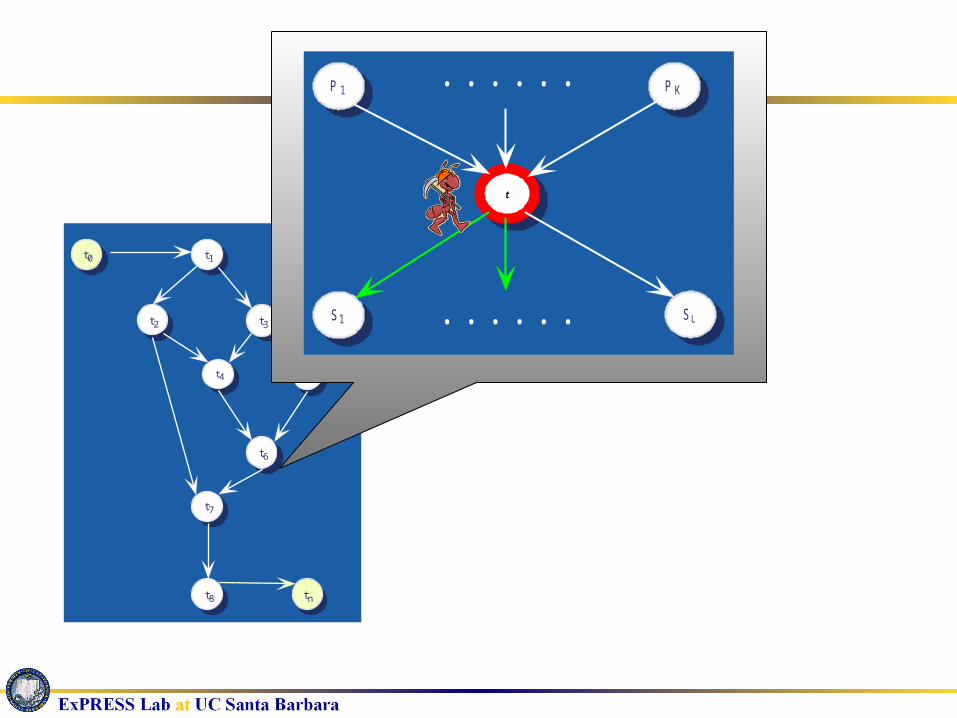
Ant Search Strategy
Each ant traverses the graph in topologically sorted orderGuarantees that each inbound edge to the
current node has been already examinedAt each node, the ant will:
Make guesses for the coloring of the successor nodes
Make decision on the coloring of the current node

Ant Search Strategy
At task node ti, the ant makes guesses the coloring for each of the successor nodes tj :
ij(k) : global heuristic on coloring tj with ck
j(k) : local heuristic on coloring tj with ck
)2((l)η(l)τ
(k)η(k)τ(k)p
1,2l
βj
αij
βj
αij
ij
)3(k)area(j,wk)time(j,w
1
k)cost(j,
1(k)η
atj

Solution Construction
Upon entering a new task node ti, the ant makes a decision on the coloring of ti :probabilistically based on the guesses made by all
the immediate precedents of ti
Inbound edges are correspondingly colored once this decision is made
)4( of precedents immediate ofcount
for guess ofcount (k)pi
i
ik
t
tc

t1
t2 t3
t4 t5
t6
t7
t8
t0
tn
P 1 P K
t
S1 SL. . . . . .
. . . . . .

t1
t2 t3
t4 t5
t6
t7
t8
t0
tn
P 1 P K
t
S1 SL. . . . . .
. . . . . .

t1
t2 t3
t4 t5
t6
t7
t8
t0
tn
P 1 P K
t
S1 SL. . . . . .
. . . . . .
t1
t2 t3
t4 t5
t6
t7
t8
t0
tn
P 1 P K
t
S1 SL. . . . . .
. . . . . .

t1
t2 t3
t4 t5
t6
t7
t8
t0
tn
P 1 P K
t
S1 S L. . . . . .
. . . . . .

t1
t2 t3
t4 t5
t6
t7
t8
t0
tn
P 1 P K
t
S1 S L. . . . . .
. . . . . .

t1
t2 t3
t4 t5
t6
t7
t8
t0
tn
P 1 P K
t
S1 S L. . . . . .
. . . . . .

t1
t2 t3
t4 t5
t6
t7
t8
t0
tn
P 1 P K
t
S1 S L. . . . . .
. . . . . .
t1
t2 t3
t4 t5
t6
t7
t8
t0
tn
t1
t2 t3
t4 t5
t6
t7
t8
t0
tn
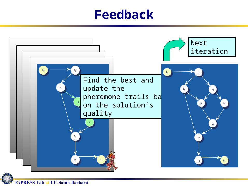
Find the best and update thepheromone trails based on the solution’s quality
t1
t2 t3
t4 t5
t6
t7
t8
t0
tn
Next iteration
Feedback

Experimental Setup
Testing benchmarks: DAGs of different sizes are generated randomly with average
branching factor of 5 Real functions (in C/C++) extracted from the MediaBench
suits are mapped onto the task nodes Tasks are analyzed using SUIF and Machine SUIF tools to
achieve detailed CDFG level description Simplified communication interface between tasks Major problem: Real applications task graphs
Goal: Find the optimal resource partition that achieves the best worst case execution time under FPGA area constraint

Definitive Quality Assessment
91.7% of the results are within the top 3%
77% of the results of AS are within the top 2%
63.5% of the results are within top 0.1%
Comparing AS results with brute force searchOffers definitive measurement for the qualityGives full solution space (can filter out EASY cases)

Result Quality Assessment
33 difficult testing cases
325 possible partitions
SA-50 has comparable run time as the AS
SA-500 and SA-1000 runs at 10 and 20 times
Larger testcases – too big for brute force search Comparison with Simulated Annealing

Code Generation
Once task graph is partitioned Generate code for each task Create communication protocols
Bus creation & arbitration Memory hierarchy Currently assume simple direct communication
Need code generation from every input specification to every computational core Software – use conventional compiler flow Hardware – need flow from task to HDL
Scheduling is fundamental problem for both hardware and software synthesis

Instruction Scheduling
Given: set of instructions and collection of computational units
Instruction modeled using data flow graph (DFG) Directed acyclic graph Each node is instruction Each edge is a data dependence
Find schedule for instructions to minimize some function (latency, area, power, …)
Auto Regressive Filter

Instruction Scheduling
NP-hard Fundamental problem - many different heuristic methods
have been developed ILP Force directed Genetic algorithm Path based Graph theoretic Computational geometry List scheduling
+
NOP
+ <
-
-
NOP
1
2
3
4
v2v1
v3
v4
v5
vn
v6
v7
v8
v9
v10
v11
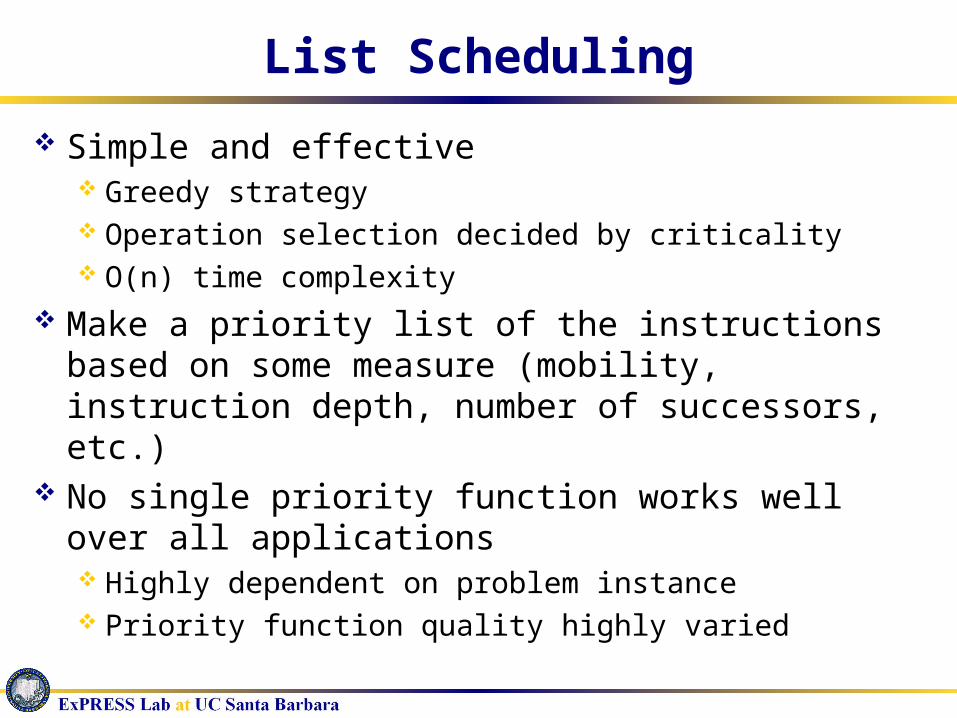
List Scheduling
Simple and effective Greedy strategy Operation selection decided by criticality O(n) time complexity
Make a priority list of the instructions based on some measure (mobility, instruction depth, number of successors, etc.)
No single priority function works well over all applications Highly dependent on problem instance Priority function quality highly varied

Combining Ants and Lists
Ants determine priority list List scheduling framework evaluates the
“goodness” of the list
+
NOP
+ <
-
-
NOP
1
2
3
4
v2v1
v3
v4
v5
vn
v6
v7
v8
v9
v10
v11

Ant Search Strategy
Every iteration each ant creates a priority listFill one instruction at a timeMemory about instructions already selectedAt step j ant has already selected j-1
instructionsjth instruction selected probabilistically

Ant Search Strategy
ij(k) : global heuristic (pheromone) for selecting instruction i at j position
j(k) : local heuristic – can use different properties Instruction mobility (IM) Instruction depth (ID) Latency weighted instruction depth (LWID) Successor number (SN)
, control influence of global and local heuristics

Pheromone Model
Each instruction opi I associated with n pheromone trails where j = 1, …, n
ij(k) indicates the favorableness for opi to be positioned at jth position in the priority list
Initially all set to fixed value 0
Evaporation rate
ij

ARF Pheromones

Experimental Results
ILP (optimal) using CPLEX List scheduling
Instruction mobility (IM), instruction depth (ID), latency weighted instruction depth (LWID), successor number (SN)
Ant scheduling results using different local heuristics (Averaged over 100 runs)

Other Topics of Research
Data & computation layout – simultaneous distribution of data/computation, utilizing on-chip block RAM, exploiting parallelism,
DSP synthesis – optimization of polynomial expressions, synthesizing multiple constant multiplications to hardware
Low power microarchitecture techniques – cache design to minimize leakage current, configurable memory hierarchy to minimize power, prefetching to minimize power

ExPRESS Group
ExPRESS - EXtensible, Programmable, Reconfigurable Embedded SystemS
Extensible – customized processors, configurable instruction sets
Programmable – post-manufacturing customization Reconfigurable – rapid configuration changes
ASIC
RISC
RAM
FPGA
ARM
DSP
System On Chip (SOC)

More ExPRESS Information…
MembersPhD Students
Wenrui GongAnup HosangadiYan MengGang Wang
UndergradsDaniel GrundWillis Hoang
Webpage - http://express.ece.ucsb.edu/
Extra Slides

Radiolocation (GSIC)
From A/D
)1( sj MNr )2( s
j MNr )1(jr )0(jr
11 )( sMNbS
21 )( sMNbS
11 )( bS 01 )( bS
)(nr
1)( 1 js qMN
bS 21 1)( js qMN
bS121 )(
jqbS
111 )( jq
bS
1
ˆ
jqf
Address/Shift Left by qj-1-1
Multiply/Accumulate
r0(n)=r(n)
Signal Vector – Zero Shift
Signal Vector Shifted Left by qj-1-1.
1)( blS 0)( b
lS1)( sMNblS 2)( sMN
blS
121 ,...,,,1by Left ift Address/Sh jqqqifori
iMNbl s )(S 1)( iMN
bl s
S ibl 2)(S
ibl 1)(S
2||||
1biS
if̂2
2|||| biS
jq
121 ,...,,
maxarg
jqqqi
1
ˆ
jqf 1
ˆ
jqf 1
ˆ
jqf
Multiuser Detection
)(nkr )|1(ˆ nnP
k f
SampleKalmanFilter
z-1
z-1
WeightUpdate
)(1 nw
)(1 nTk)|1(ˆ nni
k f
MMSE Detector )(ˆ1 nbk
SampleKalmanFilter
z-1
z-1
WeightUpdate
)(nwP
)(nT Pk
)|1(ˆ nnPk f
MMSE Detector )(ˆ nbP
k

Underwater Acoustic Receiver
EKF
skTc
v̂
skTc
v
ˆ1
sf kTc
vN
ˆ1
s
s
Nnc
v
nNc
vk
)1(ˆ
1
ˆ1
)(kr
bT
Re
..cc
)(nU
0̂f
1̂f
1ˆ
fNf
)ˆ( slp kTs

Filters
Finite Impulse Response

Auto Regressive Filter