anycubic - supereyes
TRANSCRIPT

ANYCUBIC

ANYCUBIC

ANYCUBIC
Safety Instructions
Please read the safety instructions carefully before get started.
ANYCUBIC 3D printer generates high temperature. Do not reach
inside of the printer during operation. Allow time for the printer to
cool down after printing. Contact with the extruded material may
cause burns. Wait for printed objects to cool before removing them
from the build platform.
ANYCUBIC 3D printer includes moving parts that can cause injury.
Vapors or fumes may be irritating at operating temperature. Always
use the ANYCUBIC 3D printer in an open, well ventilated area.
Be cautious when using the scraper. Never direct the scraper
towards your hand.
The ANYCUBIC 3D printer MUST NOT be exposed to water or rain.
The ANYCUBIC 3D printer is designed to be used within ambient
temperature ranging 8ºC-40ºC, and humidity ranging 20%-50%.
Working outside those limits may result in low quality printing.
In case of emergency, immediately turn off the ANYCUBIC 3D
printer.
It is recommended to use protection glasses when cleaning/sanding
printed models to avoid small particles contacting eyes.
Never leave the ANYCUBIC 3D printer unattended during operation.
ANYCUBIC
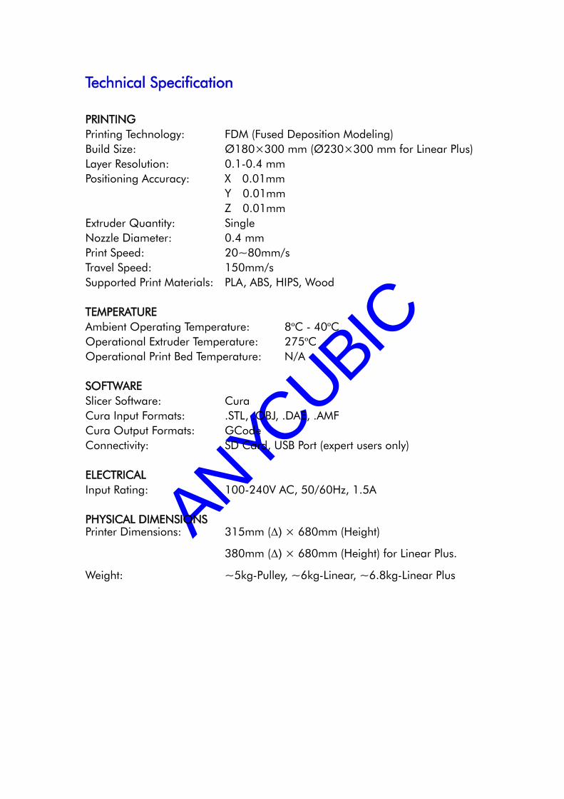
Technical Specification
PRINTING
Printing Technology: FDM (Fused Deposition Modeling)
Build Size: Ø 180× 300 mm (Ø 230× 300 mm for Linear Plus)
Layer Resolution: 0.1-0.4 mm
Positioning Accuracy: X 0.01mm
Y 0.01mm
Z 0.01mm
Extruder Quantity: Single
Nozzle Diameter: 0.4 mm
Print Speed: 20~80mm/s
Travel Speed: 150mm/s
Supported Print Materials: PLA, ABS, HIPS, Wood
TEMPERATURE
Ambient Operating Temperature: 8ºC - 40ºC
Operational Extruder Temperature: 275ºC
Operational Print Bed Temperature: N/A
SOFTWARE
Slicer Software: Cura
Cura Input Formats: .STL, .OBJ, .DAE, .AMF
Cura Output Formats: GCode
Connectivity: SD Card, USB Port (expert users only)
ELECTRICAL
Input Rating: 100-240V AC, 50/60Hz, 1.5A
PHYSICAL DIMENSIONS Printer Dimensions: 315mm (Δ) × 680mm (Height)
380mm (Δ) × 680mm (Height) for Linear Plus.
Weight: ~5kg-Pulley, ~6kg-Linear, ~6.8kg-Linear Plus

ANYCUBIC
Shenzhen Anycubic Technology Co., Ltd.
Assembly Instructions
Mechanics ..................................................................................................................... 1
1. Top and bottom triangle .................................................................................. 1
2. Effector ............................................................................................................... 3
3. Slide guide (Linear and Pulley) ....................................................................... 5
4. Main frame ....................................................................................................... 8
5. Belts .................................................................................................................... 9
6. Extrusion system .............................................................................................. 10
Circuit .......................................................................................................................... 11
7. Mainboard ...................................................................................................... 11
8. LCD .................................................................................................................. 14
9. Platform ........................................................................................................... 14
Setup ............................................................................................................................ 16
1. Driver Installation ........................................................................................... 16
2. Firmware uploading ....................................................................................... 16
3. Parameter settings .......................................................................................... 18
4. Printing ............................................................................................................. 20
5. Supplementary for Linear Plus ...................................................................... 23
FAQ .............................................................................................................................. 25
If you have any question or suggestion, please contact us on

ANYCUBIC
Shenzhen Anycubic Technology Co., Ltd.
Parts List
No. Items/Quantity No. Items/Quantity
A01 Top triangle × 3 B01 XYZ Motor × 3 (with wire)
A02 Bottom triangle × 3 B02 Print head set × 1
A03 Effector × 1 B03 4010 fan × 1 (with wire & end)
A04 Horseshoe fixture × 1 B04 4010 air blower × 1 (with wire & end)
A05 Radiator cover × 1 B05 Limit switch × 3
A06 Air nozzle × 1 B06 Wire for limit switch× 3 pairs
A07 Belt tensioner × 3 B07 Wire terminal for limit switch × 3
A08 Stop blocks × 6 (Pulley× 3) B08 Extrusion motor × 1
A09 Carriage × 3 (Pulley only) B09 ANYCUBIC mainboard × 1
A10 Extrusion bearing holder × 1 B10 Al-fin × 5
A11 Extrusion fixture × 1 B11 A4988 driver × 5
A12 Extruder rack × 1 B12 LCD 2004 × 1 (with pin board & wire)
A13 Shaft sheath × 1 B13 USB wire × 1
A14 Mainboard holder × 1 B14 Power adaptor × 1
A15 LCD cover × 1 B15 SD card × 1
A16 Limit blocks for print platform × 6
C01 M5*25 screw × 9 (Pulley only) D01
240mm Al-extrusion × 9 (300mm for
Linear Plus) C02 M3*20 screw × 9
C03 M3*16 screw × 13 D02 680mm Al-extrusion × 3
C04 M3*12 screw × 1 (Pulley × 14) D03 Idler wheel × 3
C05 M3*10 screw × 8 D04 Synchronizing wheel × 3
C06 M3*8 screw × 50 (Pulley × 20) D05 Carbon fiber tube set × 6
C07 M2.5*12 screw × 11 D06 Linear rail × 3 (Linear only)
C08 M2*5 screw × 8 D07 Pulley wheel (Bearing) × 9 (Pulley only)
C09 Ø4-7-0.5 washer × 2 D08 4.5m Synchronous belt × 1
C10 M3 flange nut × 18 (Linear only) D09 Belt tension spring × 3
C11 M4 square nut × 67 (Pulley × 64) D10 Extrusion wheel × 1
C12 M5 hex nut × 9 (Pulley only) D11 Extrusion bearing × 1
C13 M4 hex nut × 3 D12 Extrusion spring × 1
C14 M3 hex nut × 16 (Pulley × 19) D13 M6 Quick connector × 1
C15 M4*8 screw × 6 D14 0.6m PTFE feeding pipe × 1
C16 M4*10 screw × 59 (Pulley × 56) D15 0.8m Strap × 1
C17 M4*12 screw × 1 D16 PTFE washer × 4
C18 M4*25 screw × 3
D17 Ø200mm Glass plate × 1 (Ø240mm for
Linear Plus) C19 Copper spacer × 12
C20 M3*25 screw × 6
Other
Hex key set (1.5/2/2.5/4mm) × 1 Rubber glove × 1 pair
Test filament × 1

ANYCUBIC
Shenzhen Anycubic Technology Co., Ltd.
1
Mechanics
Fasteners Listing
Note: A flat surface is recommended for the assembly. Hex keys are available within the
package. Take care of the scrap when unpack Al-extrusions and keep it away from children.
1. Top and bottom triangle
Step 1. Firstly, hang but not tighten 5 pairs of C16 and C11 onto A01 as shown in Fig 1.
Then push an Al-extrusion (D01) through two screws along A01 and tighten the
corresponding screws. Lastly, fix one pair of C13 and C18 onto A01 as shown in top-left.
Fig 1
Step 2. Place 3 pieces of assembled A01 and D01 on a flat surface with back side face
down, as shown in Fig. 2. Then, follow the blue arrows, slowly push forward those 3 parts to

ANYCUBIC
Shenzhen Anycubic Technology Co., Ltd.
2
form a triangle and tighten the corresponding screws (red arrows).
Fig. 2
Step 3. Fig. 3 shows the assembly details of one of the three corners of the top triangle.
Fig. 3
Step 4. The assembly of bottom triangle is the same as the top, except 10 pairs of C16 and
C11 and 2 pairs of short Al-extrusion are used for A02, which is show in Fig. 4.
Fig. 4
Step 5. After 3 pieces of assembled A02 are ready, push them forward simultaneously to
form the bottom triangle and then tighten the corresponding screws, just as Fig. 5 shows.

ANYCUBIC
Shenzhen Anycubic Technology Co., Ltd.
3
Fig. 5 Fig. 6
Step 6. Fig.6 shows the assembly of 3 stepper motors. After assembly, using C06 to fix those
motors to each corners of the bottom triangle as demonstrated in Fig. 7. Make sure the
sockets of the motors face up.
Fig. 7
2. Effector
Step 1. Before installation, detach the heat rod and thermistor from the hot end set. Then
install the Hot End to the radiator cover (A05) by a horseshoe (A04), as shown in Fig 8.
Leave the C06 screws untightened in order to adjust the hot end angle later if necessary.

ANYCUBIC
Shenzhen Anycubic Technology Co., Ltd.
4
Fig. 8
Step 2. As shown in Fig. 8 (3) and (4), find the suitable angle to fix the Hot End into A03.
Then fix the heat rod and thermistor back. After, use 4 pieces of C08 to fix the air nozzle
(A06). Lastly, fix B03 and B04 (fans) to the correct side of the radiator cover.
Step 3. Fix 6 carbon fiber tubes (CFT, D05) onto A03 using C02 and C19, shown in Fig. 9.
Note the direction of C19, the copper spacer.
Fig. 9
Step 4. Fig. 10 shows the assembly of 3 belt tensioners which connected to the CFTs. Please
note the suggested height of the top screws (C07) is 8mm.

ANYCUBIC
Shenzhen Anycubic Technology Co., Ltd.
5
Fig. 10
3. Slide guide (Linear and Pulley)
The operation of effector depends on the linear motion of each belt which is connected to
stepper motor. The type of motion guide is divided into Linear and Pulley. The assembly of
those two types will be introduced in the following section.
First of all, find 3 pieces of long Al-extrusions and fix them from the upper side to the bottom
triangle as shown in Fig. 11. If choose the wrong side, the Al-extrusion would not fit in. Next,
tighten the corresponding screws at each corner which is shown by red arrows.
Fig. 11
The following section is interpreted based on two different types, Linear and Pulley.
(1) Linear Version
Step 1. Firstly, hang 6 pairs of C06 and C10 with proper interval onto the linear rail (D06)
as demonstrated in Fig. 12. In total there are 3 rails and the assembly is the same.

ANYCUBIC
Shenzhen Anycubic Technology Co., Ltd.
6
Fig. 12 (the color of the linear rails might be different from this image)
Step 2. Prepare 2 pieces of stop blocks (A08) with C16 and C11. Then push down one of
the stop blocks, the linear rail, and the other stop block sequentially along with the long
Al-extrusion as shown in Fig. 13. The suggested distance between the stop block and the top
of the long Al-extrusion is 30mm. Do the same to the rest of the 2 long Al-extrusions.
Fig. 13
Step 3. Use 4 screws (C06) to fix belt tensioner onto the linear rail as shown on the left of Fig.
14. Then do the same to the rest as shown on the right side of Fig. 14.

ANYCUBIC
Shenzhen Anycubic Technology Co., Ltd.
7
Fig. 14
(2) Pulley Version
Step 1. As shown in Fig. 15, fix 3 pulley wheels (D07) to the carriage (A09) using 3 pairs of
C01 and C12. Insert C14 into the dash-circle area and fix a C04 screw from the side. Do
not over tighten or twisting the carriage. Do the same to the rest of 2 carriages.
Fig. 15
Step 2. As shown in Fig. 16, fix the prepared belt tensioners to the carriage sets using C04.
Fig. 16
Step 3. Slide down those 3 carriages along with each Al-extrusion. Then fix 3 stop blocks
using C16 and C11 and the suggested distance from the stop block to the top is 30mm.

ANYCUBIC
Shenzhen Anycubic Technology Co., Ltd.
8
Fig 17
4. Main frame
The assembly of main frame and limit switches is the same for both Linear and Pulley
version. Here we take Linear version for example.
Step 1. Fix the limit switches (B05) to each of the stop blocks as shown in Fig. 18.
Fig. 18 Fig. 19
Step 2. As shown in Fig. 19, install the top triangle frame to the main structure. Meanwhile
adjust the screws (red arrows) to level the upper surface of the triangle frame with the top of
each Al-extrusion. Fasten the 3 screws on the side (green arrow) after leveling.
Step 3. Install one end of the wire (B06) to the limit switch through the top triangle frame (no
positive and negative). Lead the other end of the wire passing through the hole of the
Al-extrusion and the holes of the bottom triangle, which is shown in Fig. 20. After that, fix

ANYCUBIC
Shenzhen Anycubic Technology Co., Ltd.
9
the bottom end of B06 into the terminal of B07. Do the same to the rest of limit switches.
Fig. 20
5. Belts
The assembly of belt is the same for both Linear and Pulley version. We take the Linear
version for example. Divide the belt into 3 equal parts. Fix one end of a belt onto the belt
tensioner as shown in Fig. 21-1. Thread the belt through the top guiding wheel, then the
bottom synchronizing wheel, and lastly fix the other end of the belt back to the belt tensioner,
Fig. 21-4. Do the same to the rest of 2 belt parts. If necessary, use the belt tension spring
(D09) to adjust the tightness of the belts.
Fig. 21
D09

ANYCUBIC
Shenzhen Anycubic Technology Co., Ltd.
10
6. Extrusion system
Fig. 22
Step 1. As shown in Fig. 22, firstly fix the extrusion wheel (D10) onto the shaft of the
extrusion motor (B08). Make sure the fastening screw is facing the plane of the shaft. Notice
the distance between the extrusion wheel and the motor is about 3mm. Next, install the
extrusion bearing with 2 washers onto the bearing holder as shown on the right of Fig. 22.
Step 2. The assembly details (from right to left) of the extruder are shown in Fig. 23. The
socket of the extrusion motor is suggested to face down (blue dash circle).
Fig. 23
Step 3. As shown in Fig. 24, lie down the main frame and choose one of the 3 long
Al-extrusions to fix the extruder on by using 2 pairs of C15 and C11. The position of the
extruder should be a bit lower from the middle, which could be seen in the cover page. Next,
find the quick connector (D13) and the feeding pipe (D14) and fix them onto extruder.
Fig. 24

ANYCUBIC
Shenzhen Anycubic Technology Co., Ltd.
11
Step 4. Insert the other end of the feeding pipe to the other quick connector on the effector.
If you wish to pull out the feeding pipe, please press down the black plastic ring then release
the pipe. Do not force the pipe out by twisting or tearing.
Fig. 25
Circuit
7. Mainboard
Step 1. Fix ANYCUBIC mainboard (B09) to the holder (A14) using 3 pairs of C06 and C14.
Fig. 26
Step 2. There are 5 pieces of A4988 (B11) in the package. Prepare 4 pieces (the rest is for
backup) of A4988 with Al cooling fin, as Figure 27 shows. Make sure the Al fin does not
touch the pin on A4988 to avoid any short passing.
*A method to calculate the drive current of A4988: use a multimeter to test the voltage
between the two points on A4988, which is pointed out by two red arrows as shown in Fig.
27; then the current (I) can be calculated by the equation of I=U/0.8. Normally the voltage
ranges from 0.75 to 1V, so the current should be in the range of 0.94~1.25A.

ANYCUBIC
Shenzhen Anycubic Technology Co., Ltd.
12
Fig. 27
Step 3. As shown in Fig. 28, mount 4 pieces of square nuts (C11) into the corresponding
position on bottom Al extrusion, and fix ANYCUBIC mainboard using 4 pieces of C15. Note:
in Fig. 28, 3 motors are named as X, Y, Z respectively in order to make the
wiring/interpretation clearer in the following paragraph. The assembly position of
ANYCUBIC mainboard could be referred to those 3 motors.
Fig. 28
Step 4. Next, as shown in Fig. 29, fix 4 pieces of A4988 onto ANYCUBIC mainboard. Pay
closely attention to the configuration and direction of the drivers and board to avoid any
unnecessary problem/damage during use.

ANYCUBIC
Shenzhen Anycubic Technology Co., Ltd.
13
Fig. 29
Step 5.
The wiring of the mainboard is explained as follows (Figure 30). Before wiring on
ANYCUBIC mainboard, please make sure the wires on effector passing through the carbon
fiber tubes, as shown in Figure 31.
Fig. 30
a. The assembly of A4988 has been mentioned previously.
b. Limit switches (ENDSTOPS): please see the bottom right in Fig. 30. 1. X+ wire to X
motor limit switch; 2 Y+ wire to Y motor limit switch; 3. Z+ wire to Z motor limit switch.
c. Thermistor: wire the thermistor terminal from the printing head to T0.

ANYCUBIC
Shenzhen Anycubic Technology Co., Ltd.
14
d. Motors: X, Y, Z slots are for X, Y, Z motors respectively. There are 2 slots for Z motor,
please choose any one of them. E0 is for extrusion motor. (E1 is for expansion function
such as two extruders).
e. Heat rod: wiring from printing head to Heat 0 port (without positive and negative).
f. Fan: connect the 4010 cooling fan to FAN 2 slot, while connect the 4010 blower fan (for
model cooling) to FAN 0 slot. Red line wires to positive terminal and black one wires to
negative terminal.
g. Power and USB: when everything is ready, connect power supply to the power port and
USB line to the USB port.
When wiring is finished, use straps (D15) to arrange the wires from printing head, as shown
in Fig. 31. The wire-cluster could be fixed to one of the carbon fiber tubes by ribbon, but do
not let it to restrict or interfere with the motion of the printing head.
Fig. 31
8. LCD
Firstly prepare the LCD with the LCD cover (A15) and other fasteners as shown in Fig. 32.
Then use the cables to wire EXP1 and EXP2 from mainboard to LCD. Lastly, fix the LCD to
the bottom Al-extrusions, just as shown in Fig. 32.
9. Platform
As shown in Fig. 33, install 6 pieces of limit-blocks (A16, including right and left parts) onto
the bottom triangle frame using 6 pairs of C16 and C11. Then put the glass platform onto
A16 and adjust its position accordingly. Lastly, fasten those screws to fix the platform. Then
you could fix the ANYCUBIC platform sticker onto the glass platform.

ANYCUBIC
Shenzhen Anycubic Technology Co., Ltd.
15
Fig. 32
Fig. 33
Till now, the assembly is finished and next we will show how to setup the machine.

ANYCUBIC
Shenzhen Anycubic Technology Co., Ltd.
16
Setup
1. Driver Installation
*Note: We might update the firmware and software from time to time.
Please refer to the latest version via the link below:
https://drive.google.com/open?id=0B8VIB533cgdMSVMxNm43aG1OQ0U
ANYCUBIC mainboard uses CP2012 chip for communication. Normally, when printer
connects to PC via USB for the first time, the PC will automatically install the driver for
CP2102. The corresponding port name will appear in Device Manager of the PC. The port
number is random but it keeps the same if using the same mainboard and USB port.
If auto installation fails, the reason could be that the PC system is a simplified version or has
been modified. Please unzip the file “Drivers for CP2102”, and install the driver manually.
2. Firmware uploading
Step 1. The installation of Arduino is shown in Figure 34, double click ‟arduino - 1.6.4 -
windows.exe‟, then click „I Agree‟ in the installation dialogue and click „Next‟ and choose
the „installation path‟ if necessary till finally see the „Install‟ button then click it to start. When
installation finished, close the dialogue interface and a shortcut of „Arduino‟ would appear
on PC desktop, which means it has been successfully installed.
Fig. 34
Step 2. Uploading the firmware to ANYCUBIC mainboard. After the installation of „Arduino‟,
unzip the „Firmware for ANYCUBIC Kossel 3D printer‟, and find „*.ino‟ file then double click
to open it.
Next, as Fig. 35 shows when the interface appears, please do as the follows: (1) click
„Tools‟-„Board‟, and then select „Arduino Mega or Mega 2560‟; (2) select
„Tools‟-„Processor‟-„ATmega 2560(Mega 2560)‟; (3) select „Tools‟-„Port‟-„COM4 (Arduino
Mega or Mega 2560)‟ (the same as ANYCUBIC Mainboard Port number).

ANYCUBIC
Shenzhen Anycubic Technology Co., Ltd.
17
Fig. 35
Lastly, click the upload icon to upload the firmware, as Fig. 36 shows. The uploading
status will show at the bottom as „Compiling sketch‟, „Done Compiling‟, „Uploading‟, and
„Done uploading‟. After that, the LCD starts to display the information as shown in Fig. 37.
(Close other software that occupy the COM Port when uploading firmware by Arduino)
Fig. 36

ANYCUBIC
Shenzhen Anycubic Technology Co., Ltd.
18
Fig. 37
3. Parameter settings
The provided firmware has been generally debugged and modified. But inevitably there are
some small deviations still. So some critical parameters that affect the printing quality need
to be adjusted on a case-by-case basis. Before start, connect the printer with the power
(B14), the 4010 radiator cooling fan should be on if the temperature is higher than 6ºC,
otherwise, check the wiring and fix it. This fan is important for eliminating the possibility of
nozzle clogging.
Step 1. Heights
First, install the „Printrun‟ software. Upzip the „Printrun-Win-Slic3r-03Feb2015‟ (or
„Printrun-Mac-03Feb2015‟), and double click the „pronterface.exe‟ to enter the dialogue
which is shown in Fig. 38 Choose the correct port and baud rate (red square) then click
connect (green square) to control the 3D printer via computer. You could disconnect it using
the same button.
Fig. 38
Second, auto-home. As shown in the bottom right of Fig. 38, enter „G28‟ (the code for
auto-home) then click „send‟ to return the nozzle home (back to top). If the nozzle heading
to the opposite direction, that means the wiring of X, Y and Z motors on Ramps 1.4 board is
opposite.
Third, adjust the height parameters in firmware. After auto-home, place a piece of paper to
the center of the print platform, enter the code of „G1Z100‟ in Printrun dialogue then click

ANYCUBIC
Shenzhen Anycubic Technology Co., Ltd.
19
„send‟ to move the nozzle to the Z axis position of height=100mm (the distance between the
nozzle and the print platform). Next, on the one hand observe the actual heights of Z axis,
on the other hand, carefully reduce the heights value step by step, such as G1Z50, G1Z30,
G1Z10, G1Z3, G1Z2.5, G1Z2.3… to slowly move the nozzle close to the platform. (Note: if
the value is set too large, the nozzle may knock at the platform. If so, immediately cut off the
power, then plug in again and enter G28 for auto home and do the adjustment again.)
If everything goes fine, when the nozzle touches the paper and a bit resistance could be felt
if pulling the paper, it means the height is OK. Now, check the value of G1Z# (or directly
check the Z# from LCD). # is the actual height value (which theoretically should be zero
when nozzle touching the paper). For example, if Z value on LCD is Z001.2, it means that
the difference between the actual height and the set height in firmware is 1.2mm, so the
height in firmware should be reduced by 1.2mm. (Given the height in the firmware is
300mm, now it should be changed into 300-1.2=298.8mm, then uploading the firmware
again). On the other side, if Z value on LCD is Z-002.3, then the height in firmware should
be changed into 300+2.3=302.3mm and re-upload the firmware.
The code for height in firmware could be located by quick searching in Arduino:
#define MANUAL_Z_HOME_POS 300 // the 300 here is the height parameter.
After re-upload the firmware, it is necessary to open the Printrun software and debug again
following previous steps to verify the result.
Step 2. Size of the print model
When the height setup is OK, it is suggested to print a test cubic model (20× 20× 10). „How
to print‟ could be referred to the next section, „Printing‟.
When the print job finished, check the actual size of the model. If it is smaller than
20× 20× 10, then it is suggested to reduce the value of „DELTA_DIAGONAL_ROD‟ (default
value=216) by 1~3 step by step until the actual size matches to 20× 20× 10.
Step 3. Leveling
There are two ways for leveling, auto-leveling and manual leveling. The auto-leveling is
discarded in this version due to its relative large errors and repeated adjustment before
every print.
For manual leveling, a circle test model is provided in the link before. When it prints the first
layer, please observe the nozzle height and position towards X, Y and Z motors, and the
height of the nozzle can be adjusted by changing the tightness of the screw on the top of the
corresponding belt tensioners (refer to Fig. 10). Because the tightness of this screw can lead
to distance change between limit switches and effector, thereby changing the nozzle height.
Specifically, tighten this screw when nozzle is too high, and loose this screw when nozzle is
low. Using this method, the machine does not need leveling again in a relative long time.
Step 4. Eliminating concave and convex
When printing a model with large size, it may produce concave-convex on the model. In

ANYCUBIC
Shenzhen Anycubic Technology Co., Ltd.
20
order to tackle this problem, the value of „DELTA_SMOOTH_ROD_OFFSET‟ in the firmware
should be changed by 1~3 step by step (default value =151) and then re-upload the
firmware. It is suggested to increase this value if the resulting model has a convex surface,
while decreasing this value if the resulting model has a concave surface.
Step 5. Extrusion output
Open „Printrun‟, and preheat the nozzle temperature to 190 degree C and set the extrusion
length as 100mm long. At the same time, mark the filament in order to see the actual
extrusion length. If the actual extrusion length is 100± 2mm then it is fine. If the actual
extrusion length is 80mm for example, then the corresponding parameter in firmware
should be modified. The default value of this parameter in firmware is 96, so if the actual
extrusion value is 80mm, this parameter should be changed into 96× (100/80)=120.
The corresponding code in firmware could be located by searching:
#define DEFAULT_AXIS_STEPS_PER_UNIT {XYZ_STEPS, XYZ_STEPS, XYZ_STEPS, 96} where
the 96 here is the length parameter.
4. Printing
Step 1. Installation of the slicing software. Cura is used for example. Double click
„Cura_15.04‟ to proceed with the installation. When the dialogue appears you may tick all
the boxes as shown in Fig. 39.
Fig. 39
Step 2. Configuration. When finishing the installation and opening „Cura‟ for the first time,
a configuration dialogue would appear. Choose the „language‟ that suits you and click
„Next‟ if necessary. When come across „Select your machine‟, please choose „Other‟ and hit
„Next‟ and choose „DeltaBot‟ in the following dialogue, which is shown step by step in Fig.

ANYCUBIC
Shenzhen Anycubic Technology Co., Ltd.
21
40. Lastly, click „Finish‟ to complete the configuration and enter the home interface of Cura.
Fig. 40
Step 3. Printing parameter settings. At the home interface of Cura, click „Machine‟ and in
the drop-down menu choose „Machine settings‟ to open the setting interface as Fig. 41
shows. Change the maximum width, maximum depth and maximum height into 180, 180
and 300 respectively (those values should be 230, 230 and 300 if you are setting up the
ANYCUBIC Kossel Plus). Leave the „Heated bed‟ box empty to suit the current machine
version. The serial port can be AUTO, or choose the right port when you have several
devices connected. The baud rate is suggested to be 250000. Then click „OK‟ at the bottom
left to return to home interface.
Fig. 41
Next, as shown in Fig. 42, click „Basic‟ and „Advanced‟ respectively on the top left in home
interface of Cura to change the parameters to suitable values one by one. Note: the
suggested parameters in Fig. 42 may be varying depend on different models.

ANYCUBIC
Shenzhen Anycubic Technology Co., Ltd.
22
Fig. 42
Step 4. Print. To experience the very first print, please load the test model „20× 20× 10‟ and
then click the „Print with USB‟ icon on top, as shown in Fig. 43. In order to minimize the
instability from the PC and USB port, it is strongly suggested to save the model in Cura as
Gcode file into SD card and insert the SD card to 3D printer to print offline.
Fig. 43

ANYCUBIC
Shenzhen Anycubic Technology Co., Ltd.
23
5. Supplementary for Linear Plus
5.1 firmware settings
Change the parameters in firmware as the following figure shows or download the latest
firmware from Google Drive and find the firmware for linear plus:
(https://drive.google.com/open?id=0B8VIB533cgdMSVMxNm43aG1OQ0U, the same
link as the previous one.
The change made in firmware for Linear Plus is summarized as following:
DELTA_DIAGONAL_ROD change 267 to 271.5 or the number you debug;
DELTA_SMOOTH_ROD_OFFSET change 188 to 187 or the number you debug;
DELTA_PRINTABLE_RADIUS change 115 to 116;
For the limit switches have been moved down, the height need to be adjusted, and you
also need to level the platform.
5.2 Cura settings
Change the width and depth to a number big than 230 such as 240

ANYCUBIC
Shenzhen Anycubic Technology Co., Ltd.
24
Change the start distance to 0.5 (3 for default) in expert config.
To print small parts, it is suggested to change the start distance back to 3.

ANYCUBIC
Shenzhen Anycubic Technology Co., Ltd.
25
FAQ 1. LCD malfunction (no power/blank)
a. Ensure the machine is well connected to the power/PC.
b. Ensure the wiring of LCD is correct (EXP1 to EXP1; EXP2 to EXP2).
c. Ensure the firmware has been uploaded. If not, LCD would show blank.
d. Adjust the brightness by rotate the small „contrast‟ knob on the back of LCD.
2. Motor malfunction (shaking/run opposite)
a. Please check with the A4988 driver to see if the Al cooling fin contacts with the pins.
In this case A4988 is very likely damaged and need change.
b. Reverse the wiring of motor or change the firmware code (true ↔ false).
#define INVERT_X_DIR true; #define INVERT_Y_DIR true; #define INVERT_Z_DIR true
#define INVERT_E0_DIR true; #define INVERT_E1_DIR false; #define INVERT_E2_DIR false
3. Off-line print abnormal
a. Check according to Question 1.
b. Ensure the read/write of SD card is OK.
c. Ensure the file format in SD card is Gcode instead of STL, and file name should be
in English instead other languages.
4. Print head malfunction (block/leakage)
a. Block at the nozzle. Two possible causes: (1) low quality filament and (2) metal
scrap inside the nozzle. Please clean the nozzle using cleaning screw or contact us.
b. Block at the throat. Two possible causes: (1) insufficient cooling. Check the cooling
fan; and (2) careless assembly. Ensure the tube has been well screwed down.
c. Block between the quick connector and the Al radiator. The reason is most likely
insufficient cooling, so please check the cooling fan.
d. Leakage. The very likely reason is careless sealing. Please ensure each part is well
assembled or contact us for help.
5. Filament output abnormal
a. No output. Two possible causes: (1) refer to Question 4; (2) insufficient heating for
filament. Normally the printing temperature range of PLA and ABS is 180-200 and
210-240 degree C, respectively. Try to increase the printing temperature or
improve the heat insulation of the printing head.
b. Rough output. (1) Check with Question 4; (2) check with the extruder, especially the
extrusion wheel and the extrusion bearing. Clean and adjust them if necessary.
6. Print head shaking
a. Ensure the screws on carbon fiber tubes are well connected.
b. Ensure the clamp to fix the Al radiator is well fixed.
c. Check belt tensioners, pulley carriages/linear rails and the corresponding screws.
7. Print head suspending or knocking toward platform
Please refer to Parameter settings, Step 1.
8. Abnormal extrusion
Please refer to Parameter settings, Step 5.