ao-100-12-f020-199500_rev01 open
TRANSCRIPT
Topside Technical Building – Module P2 Supply Specification
Document Number:
AO-100-12-F020-199500
Revision : 01 open Status : IFR
Rev. Date : 09-Jun-2014
Doc. Type : SPE Discipline : CIV Phase: DE Class: 2 Page 1 of 43
CTR Ref.: F10282-SSA-0TP2-CIV-SPC-199500 System / Subsystem : 83 Equipment Type : QZ
This document is the property of TOTAL E&P Angola BLOCK32 and shall not be disclosed to third parties or reproduced without permission of the owner.
KAOMBO
Project
This document has been generated by an Electronic Document Management System. When printed it is considered as a “for information only” copy. The controlled copy is the screen version and it is the holder’s responsibility that he/she holds the latest valid version.
Topside Technical Building – Module P2 Supply Specification
01
open IFR 09-Jun-2014 OPEN REVISION FOR TENDER
BULLETIN A.DOUET C.BOURDON R.MAROTTE
00 IFR 15-Apr-2014 Issued for Review A.DOUET C.BOURDON R.MAROTTE
HA IDC 06-Mar-2014 Case 3 LLI Period – Interdiscipline check A.DOUET C.BOURDON R.MAROTTE
F2 IFP 28-Aug-2013 Updated for case 3 Proposal P.LEVAVASSEUR A.DOUET S.DELLION
F1 IFP 06-Aug-2013 Updated for case 3 Proposal P.LEVAVASSEUR A.DOUET S.DELLION
F0 IDC 26-Jul-2013 Issued for Case 3 Proposal A.DOUET D.McKENZIE S.DELLION
Rev. Status Date Revision Description Issued by Reviewed by Approved by
Topside Technical Building – Module P2 Supply Specification
Document Number:
AO-100-12-F020-199500
Revision : 01 open Status : IFR
Rev. Date : 09-Jun-2014
Doc. Type : SPE Discipline : CIV Phase: DE Class: 2 Page 2 of 43
CTR Ref.: F10282-SSA-0TP2-CIV-SPC-199500 System / Subsystem : 83 Equipment Type : QZ
This document is the property of TOTAL E&P Angola BLOCK32 and shall not be disclosed to third parties or reproduced without permission of the owner.
Revision list:
Rev.Nr Modifications:
00 - Class and certification requirements
- Active fire protection
- Walls finishings
01 - COMPANY comments
- Miscellaneous
Hold list:
Hold Nr Hold Description:
1 Connection of roof gutters and down pipe to the ship open drain network
2 Color of internal bulkhead finishing, raised floor, ceiling
3 Extent of external fire risk for bottom and roof deck
TABLE OF CONTENTS
1 GENERAL ..................................................................................................................................................... 5
1.1. Project presentation .............................................................................................................................. 5
1.2. Purpose of this specification ................................................................................................................ 5
2 MODULE P2 DESCRIPTION ....................................................................................................................... 7
3 DEFINITIONS AND ABBREVIATIONS ....................................................................................................... 9
3.1 Definitions .............................................................................................................................................. 9
3.2 Abbreviations ......................................................................................................................................... 9
4 BATTERY LIMITS ...................................................................................................................................... 10
5 REFERENCE DOCUMENTS...................................................................................................................... 11
5.1 Project documents .............................................................................................................................. 11 5.2 Applicable codes & standards ........................................................................................................... 11
5.3 Order of precedence ............................................................................................................................ 13
Topside Technical Building – Module P2 Supply Specification
Document Number:
AO-100-12-F020-199500
Revision : 01 open Status : IFR
Rev. Date : 09-Jun-2014
Doc. Type : SPE Discipline : CIV Phase: DE Class: 2 Page 3 of 43
CTR Ref.: F10282-SSA-0TP2-CIV-SPC-199500 System / Subsystem : 83 Equipment Type : QZ
This document is the property of TOTAL E&P Angola BLOCK32 and shall not be disclosed to third parties or reproduced without permission of the owner.
6 CLASSIFICATION AND CERTIFICATION ................................................................................................ 14
7 BASIS OF DESIGN .................................................................................................................................... 15
7.1 External Conditions ............................................................................................................................. 15 7.2 Internal Conditions .............................................................................................................................. 16
7.3 Pressurization ...................................................................................................................................... 17
7.4 Noise limits ........................................................................................................................................... 17
8 RISK ASSESSMENT .................................................................................................................................. 18
8.1 Area classification. .............................................................................................................................. 18
8.2 Fire risk assessment for external bulkheads and decks ................................................................. 18 8.3 Fire risk assessment for internal bulkheads .................................................................................... 19
8.4 Blast overpressure. ............................................................................................................................. 19
8.5 Escape ways......................................................................................................................................... 19
9 STEEL STRUCTURE ................................................................................................................................. 20
9.1 Material for structural members. ........................................................................................................ 21 9.2 Structure weight reporting .................................................................................................................. 21
9.3 In place loads ....................................................................................................................................... 22
10 CORROSION PROTECTION ..................................................................................................................... 23
11 ARCHITECTURAL REQUIREMENTS ....................................................................................................... 24
11.1 Insulation – Passive fire protection ................................................................................................... 24
11.2 Interior wall system ............................................................................................................................. 24 11.3 Finishing ............................................................................................................................................... 25
11.4 Ceiling ................................................................................................................................................... 25
11.5 Floors .................................................................................................................................................... 25
11.6 Doors ..................................................................................................................................................... 26
11.6.1 External A60/H60 doors ................................................................................................................... 27
11.6.2 Internal A60 doors ............................................................................................................................ 27 11.7 Furnishing ............................................................................................................................................ 28
12 HVAC SYSTEM .......................................................................................................................................... 29
13 ELECTRICAL SYSTEM ............................................................................................................................. 31
13.1 Lighting ................................................................................................................................................. 31
13.2 Socket outlets ...................................................................................................................................... 31
Topside Technical Building – Module P2 Supply Specification
Document Number:
AO-100-12-F020-199500
Revision : 01 open Status : IFR
Rev. Date : 09-Jun-2014
Doc. Type : SPE Discipline : CIV Phase: DE Class: 2 Page 4 of 43
CTR Ref.: F10282-SSA-0TP2-CIV-SPC-199500 System / Subsystem : 83 Equipment Type : QZ
This document is the property of TOTAL E&P Angola BLOCK32 and shall not be disclosed to third parties or reproduced without permission of the owner.
13.2.1 Welding sockets ................................................................................................................................ 31
13.2.2 Convenience sockets........................................................................................................................ 31 13.3 Cables ................................................................................................................................................... 32 13.4 Cable routing and cable segregation ................................................................................................ 32
13.5 Earthing ................................................................................................................................................ 32
13.6 MCT ....................................................................................................................................................... 33
13.7 Electrical mv, lv ups panels, batteries ............................................................................................... 33
13.8 Transformers on roof .......................................................................................................................... 34
13.9 Electrical safety kit .............................................................................................................................. 34
14 TELECOM AND INSTRUMENT SYSTEMS ............................................................................................... 35
14.1 Instrumentation panels ....................................................................................................................... 35
14.2 Telephone and Data Systems ............................................................................................................. 35
14.3 PA/GA system ...................................................................................................................................... 35
14.4 Access Control and POB System ...................................................................................................... 35
15 FIRE AND GAS SYSTEM .......................................................................................................................... 37
16 ACTIVE FIRE PROTECTION ..................................................................................................................... 39
17 COMPRESSED AIR SYSTEM ................................................................................................................... 40
18 LABORATORY ........................................................................................................................................... 41
19 ELECTRICAL AND INSTRUMENTATION WORKSHOP .......................................................................... 42
20 MISCELLANEOUS ..................................................................................................................................... 43
Topside Technical Building – Module P2 Supply Specification
Document Number:
AO-100-12-F020-199500
Revision : 01 open Status : IFR
Rev. Date : 09-Jun-2014
Doc. Type : SPE Discipline : CIV Phase: DE Class: 2 Page 5 of 43
CTR Ref.: F10282-SSA-0TP2-CIV-SPC-199500 System / Subsystem : 83 Equipment Type : QZ
This document is the property of TOTAL E&P Angola BLOCK32 and shall not be disclosed to third parties or reproduced without permission of the owner.
1 GENERAL
1.1. PROJECT PRESENTATION Refer to document n°A0-100-10-F020-090406 – Project presentation.
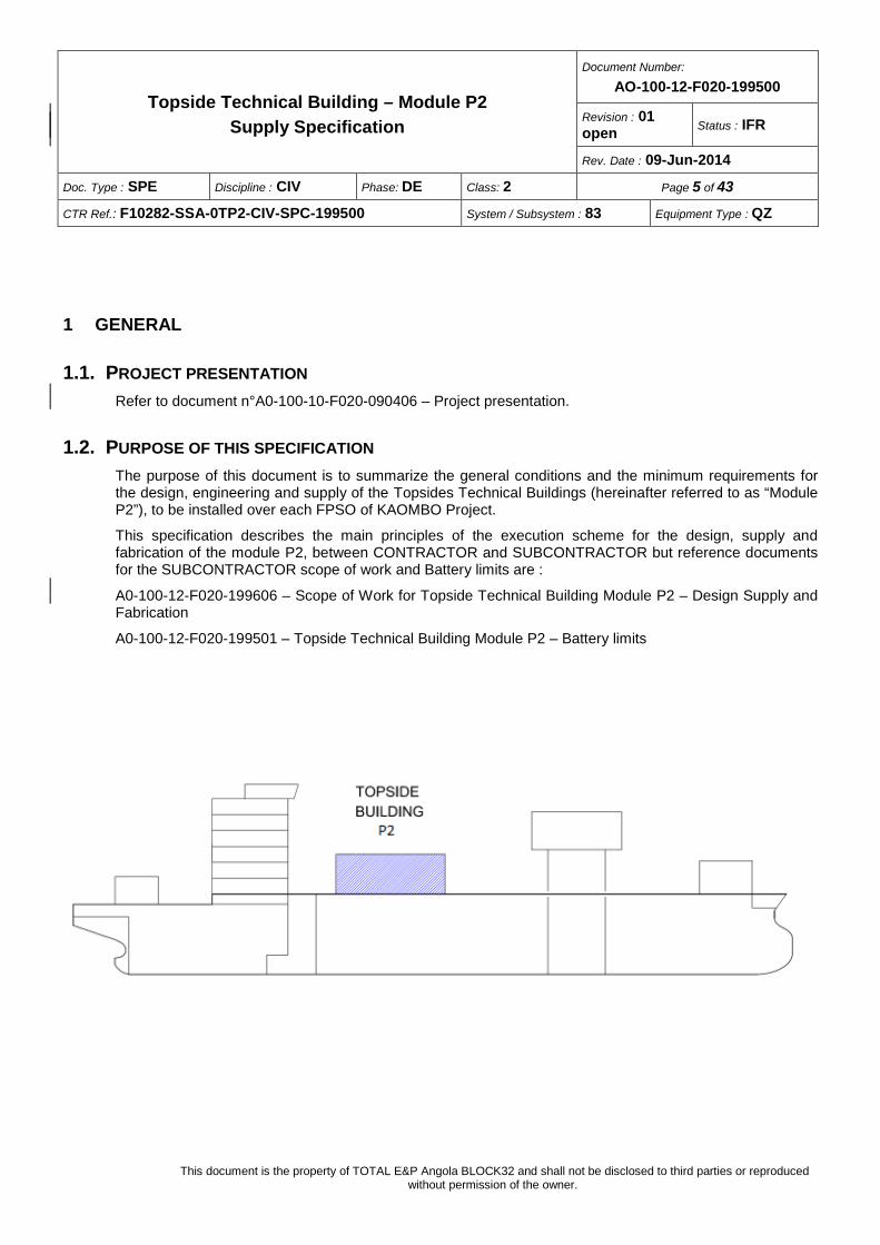
1.2. PURPOSE OF THIS SPECIFICATION The purpose of this document is to summarize the general conditions and the minimum requirements for the design, engineering and supply of the Topsides Technical Buildings (hereinafter referred to as “Module P2”), to be installed over each FPSO of KAOMBO Project.
This specification describes the main principles of the execution scheme for the design, supply and fabrication of the module P2, between CONTRACTOR and SUBCONTRACTOR but reference documents for the SUBCONTRACTOR scope of work and Battery limits are :
A0-100-12-F020-199606 – Scope of Work for Topside Technical Building Module P2 – Design Supply and Fabrication
A0-100-12-F020-199501 – Topside Technical Building Module P2 – Battery limits
Topside Technical Building – Module P2 Supply Specification
Document Number:
AO-100-12-F020-199500
Revision : 01 open Status : IFR
Rev. Date : 09-Jun-2014
Doc. Type : SPE Discipline : CIV Phase: DE Class: 2 Page 6 of 43
CTR Ref.: F10282-SSA-0TP2-CIV-SPC-199500 System / Subsystem : 83 Equipment Type : QZ
This document is the property of TOTAL E&P Angola BLOCK32 and shall not be disclosed to third parties or reproduced without permission of the owner.
Topside Technical Building – Module P2 Supply Specification
Document Number:
AO-100-12-F020-199500
Revision : 01 open Status : IFR
Rev. Date : 09-Jun-2014
Doc. Type : SPE Discipline : CIV Phase: DE Class: 2 Page 7 of 43
CTR Ref.: F10282-SSA-0TP2-CIV-SPC-199500 System / Subsystem : 83 Equipment Type : QZ
This document is the property of TOTAL E&P Angola BLOCK32 and shall not be disclosed to third parties or reproduced without permission of the owner.
2 MODULE P2 DESCRIPTION
The Module P2 is the electrical and instrumentation (E&I) building for the FPSO. It is a 2-storey building, 20m x 30m, housing the electrical room, an E&I workshop, the instrumentation and telecom room, the HVAC room, the battery room and the laboratory .
The HVAC packaged equipment shall be installed in a specifically designed HVAC room at level 2. Packaged equipment shall be designed, supplied and installed by SUBCONTRACTOR.
The module P2 will be equipped with roof gutters and down pipes, connected to the open drain network. The tie-in point with the open drain network is located at process deck level (HOLD - to be defined).
External staircases, a number of platforms and ladders shall complete the building.
The SUBCONTRACTOR will receive MV and LV Switchboards, Transformers, Batteries, UPS Panels and Telecom Panels, from CONTRACTOR as Free Issue material. For equipment and material, the following activities are to be considered as part of the scope of work :
- Equipment reception
- Preservation and storage
- Support construction
- Installation on board
- Electrical interconnecting (inside the building)
- Sea fastening
General sea fastening activities are defined in the detailed scope of work is defined in the document A0-100-12-F020-199606 – Scope of work for Topside Technical Building Module P2 – Design, procurement and fabrication.
The electrical/instrumentation interconnecting cables and cable trays between field, plant equipment and the above mentioned panels, transformers, and so on is to be considered as excluded.
However all internal power / telecom cables and piping shall be completed so as to form a complete packaged module when all internal connections have been completed.
Module P2 shall be designed for :
- Loading-out from SUBCONTRACTOR yard onto a barge (loading-out system by SUBCONTRACTOR)
- Transit situation from SUBCONTRACTOR yard to construction yard with a barge (transport and barge by CONTRACTOR)
- A single 8 points lift for lifting onto the FPSO (crane and lifting by CONTRACTOR)
- Being placed onto 4 stools on the FPSO vessel.
The Module shall be complete with all the accesses at the 2 levels and roof, with walkways, ladders, stairs and handrails.
Topside Technical Building – Module P2 Supply Specification
Document Number:
AO-100-12-F020-199500
Revision : 01 open Status : IFR
Rev. Date : 09-Jun-2014
Doc. Type : SPE Discipline : CIV Phase: DE Class: 2 Page 8 of 43
CTR Ref.: F10282-SSA-0TP2-CIV-SPC-199500 System / Subsystem : 83 Equipment Type : QZ
This document is the property of TOTAL E&P Angola BLOCK32 and shall not be disclosed to third parties or reproduced without permission of the owner.
Transformers (free-issued items supplied by CONTRACTOR) are installed on the roof. They shall be covered with a shelter. An oil containment system and access platforms shall be provided as well.
The roof shall be equipped with handrails along the perimeter.
Topside Technical Building – Module P2 Supply Specification
Document Number:
AO-100-12-F020-199500
Revision : 01 open Status : IFR
Rev. Date : 09-Jun-2014
Doc. Type : SPE Discipline : CIV Phase: DE Class: 2 Page 9 of 43
CTR Ref.: F10282-SSA-0TP2-CIV-SPC-199500 System / Subsystem : 83 Equipment Type : QZ
This document is the property of TOTAL E&P Angola BLOCK32 and shall not be disclosed to third parties or reproduced without permission of the owner.
3 DEFINITIONS AND ABBREVIATIONS
3.1 DEFINITIONS
COMPANY: TOTAL E&P ANGOLA BLOCK 32 Ltd
CONTRACTOR: means the person appointed by COMPANY for the engineering, procurement, supply, construction and commissioning of two converted FPSOs
INTEGRATION YARD: means the person in charge of the integration of the P2 modules on each FPSO
SUBCONTRACTOR: means the person appointed by CONTRACTOR to perform the WORK
WORK: means all the activities related to engineering, supply, fabrication, testing, packing, commissioning and start-up to be performed by SUBCONTRACTOR in accordance with this document and all documents referenced hereto.
3.2 ABBREVIATIONS
ATEX Atmosphere Explosive
BV Bureau Veritas
E&I Electrical and Instrumentation
ESD Emergency Shut Down
HVAC Heating, Venting and Air Conditioning
F&G Fire & Gas
FGS Fire & Gas System
FPSO Floating, Production, Storage and Offloading vessel
HIPPS High Intergity Pressure Protection System
HSSD High Sensitive Smoke Detection
ICSS Integrated Control and Safety System
Topside Technical Building – Module P2 Supply Specification
Document Number:
AO-100-12-F020-199500
Revision : 01 open Status : IFR
Rev. Date : 09-Jun-2014
Doc. Type : SPE Discipline : CIV Phase: DE Class: 2 Page 10 of 43
CTR Ref.: F10282-SSA-0TP2-CIV-SPC-199500 System / Subsystem : 83 Equipment Type : QZ
This document is the property of TOTAL E&P Angola BLOCK32 and shall not be disclosed to third parties or reproduced without permission of the owner.
MAC Manual Alarm Call Point
MCT Multi-Cables Transit System
PA/GA Public Adress and General Alarm
PCS Process Control System
PLC Programmable Logic Controller
ROR Rate-of-Rise
UCP Unit Control Panel
UPS Uninterruptible Power Supply
VLCC Very Large Crude Carrier
4 BATTERY LIMITS The principal battery limit for structure between the FPSO and Module P2 is the bottom flange of the main beam supporting the module, i.e. at the top of the pot bearings installed on the foundation stools..
At level 36.900 (process deck), peripheral walkways (plates and supporting beams) shall extend up to the plates areas supplied and installed by CONTRACTOR on the deck, so that the deck is continuous (refer to layout drawings n°AO-100-12-F020-199502).
Module P2 SUBCONTRACTOR shall provide module reactions, deflections, centre of gravity, etc under various load conditions to CONTRACTOR for design of foundation stools.
Several pipes (Fire Water or else), electrical and instrumentation cables for other floater parts/equipment will be routed and suspended under the bottom beams of module P2. These pipes and cables shall be supplied and integrated in the P2 by the SUBCONTRACTOR.
Specific disciplines battery limits are defined in A0-100-12-F020-199501 - Topside Technical Building Module P2 - Battery limits.
Topside Technical Building – Module P2 Supply Specification
Document Number:
AO-100-12-F020-199500
Revision : 01 open Status : IFR
Rev. Date : 09-Jun-2014
Doc. Type : SPE Discipline : CIV Phase: DE Class: 2 Page 11 of 43
CTR Ref.: F10282-SSA-0TP2-CIV-SPC-199500 System / Subsystem : 83 Equipment Type : QZ
This document is the property of TOTAL E&P Angola BLOCK32 and shall not be disclosed to third parties or reproduced without permission of the owner.
5 REFERENCE DOCUMENTS
5.1 PROJECT DOCUMENTS Applicable project documents are defined in :
A0-100-12-F020-199603 Requisition for TOPSIDE TECHNICAL BUILDINGS – MODULE P2
5.2 APPLICABLE CODES & STANDARDS The following codes, standards, regulations including relevant appendices and supplements, at the latest revision published, shall be complied with.
API RP 2A – WSD American Petroleum Institute, Recommended Practice for Planning, Designing and constructing Fixed Offshore Platforms – Working Stress Design 21th edition – October 2007
AISC-325 Steel Construction Manual – Edition 2005 with errata 2010, Oct,2010
AMCA Air Movement and Control Association – International
API RP 2FB Recommended Practice for the design of offshore facilities against fire and blast loading
API SPECIFICATION 2C Offshore Pedestal – Mounted Cranes - 7th edition, 2012
ASHRAE American Society of Heating, Refrigeration and Air Conditioning Engineers, Handbooks and codes
BUREAU VERITAS Rules for Classification of Ships and Offshore Units
Directive 94/9/EC European Directive on the approximation of the laws of the Member State concerning equipment and protective systems intended for use in potentially explosive atmosphere
Directive (Marine Equipment Directive) 96/98/EC as modified by Commission Directive 98/85/EC, 2001/53/EC and 2002/75/EC
Directive (97/23/EC) for Equipment under pressure of more than 0.5 bar
EN 10025 Hot rolled Products of Non-alloy Structural Steels
EN 10225 Weldable Structural Steels for Fixed Offshore Structures – Technical Delivery Conditions.
EN 14175 Fume cupboards
EN 378 Refrigerating systems and heat pumps
EN 50272-2 Safety requirements for secondary batteries and battery installations - part 2: stationary batteries
Topside Technical Building – Module P2 Supply Specification
Document Number:
AO-100-12-F020-199500
Revision : 01 open Status : IFR
Rev. Date : 09-Jun-2014
Doc. Type : SPE Discipline : CIV Phase: DE Class: 2 Page 12 of 43
CTR Ref.: F10282-SSA-0TP2-CIV-SPC-199500 System / Subsystem : 83 Equipment Type : QZ
This document is the property of TOTAL E&P Angola BLOCK32 and shall not be disclosed to third parties or reproduced without permission of the owner.
IEC 60079 Electrical apparatus for explosive gas atmospheres
IEC 60331 Fire resisting cables testing procedures
IEC 60332 Flame proof cables testing procedures
IEC 60364-5-54 Electrical installations of buildings - Part 5-54: Selection and erection of electrical equipment - Earthing arrangements, protective conductors and protective bonding conductors
IEC 60529 Degree of protection provided by enclosure (IP code)
IEC/CEI Standard for Electrical System
IMO International Maritime Organisation
IMO Resolution A468 Code on noise levels On board ships. 1982
ISO 15138 International Organization for Standardization, Petroleum and natural gas industries - Offshore production installations - Heating, Ventilation and Air-Conditioning
ISO 3740 series Related to the determination of sound power levels of noise sources using sound pressure;
ISO 3864-1 Design principles for safety signs and safety markings
ISO 7010:2011 Graphical symbols—Safety colours and safety signs—Registered safety signs
ISO 717-1 Acoustics – Rating of sound insulation in buildings and of building elements -- Part 1: Airborne sound insulation NS-5575 [28] - Ductwork Identification
ISO 7547 Ships and marine technology - Air-conditioning and ventilation of accommodation spaces Design conditions and basis of calculations
ISO 8501-1 Preparation of steel substrates before application of paints and related products—Visual assessment of surface cleanliness.
ISO 9614-1/2/3 Acoustics – Determination of sound power levels of noise sources using sound intensity;
ISO 9943 Ventilation and air treatment for galleys on board ships;
NFPA 496 Pressurization
NFPA 10 Standard for Portable Fire Extinguishers
NFPA 12 Standard on Carbon Dioxide Extinguishing Systems
NFPA 2001 Standard on Clean Agent Fire Extinguishing Systems
SMACNA Sheet Metal and Air conditioning Contractors’ National Association (Duct design, testing adjusting, balancing)
SOLAS Safety of Life at Sea, International Maritime Organisation
Topside Technical Building – Module P2 Supply Specification
Document Number:
AO-100-12-F020-199500
Revision : 01 open Status : IFR
Rev. Date : 09-Jun-2014
Doc. Type : SPE Discipline : CIV Phase: DE Class: 2 Page 13 of 43
CTR Ref.: F10282-SSA-0TP2-CIV-SPC-199500 System / Subsystem : 83 Equipment Type : QZ
This document is the property of TOTAL E&P Angola BLOCK32 and shall not be disclosed to third parties or reproduced without permission of the owner.
5.3 ORDER OF PRECEDENCE Should be any conflict, discrepancy, inconsistency or ambiguity between any of the applicable documents and codes, the following order of precedence shall be applied:
Angola-enforced Rules and Regulations (on SITE)
Flag State Regulations (during Transit) and IMO (during Transit and on SITE)
BV class and certification rules
Project technical specifications and documents (from COMPANY or CONTRACTOR)
International codes, rules and regulations (including International Marine Standards and Guidelines, Industry/Oil Industry Codes and Standards)
In case of different but not conflicting requirements, the most stringent shall be applied. In case of conflicting requirements, CONTRACTOR shall be advised in writing for settlement of the conflict.
Topside Technical Building – Module P2 Supply Specification
Document Number:
AO-100-12-F020-199500
Revision : 01 open Status : IFR
Rev. Date : 09-Jun-2014
Doc. Type : SPE Discipline : CIV Phase: DE Class: 2 Page 14 of 43
CTR Ref.: F10282-SSA-0TP2-CIV-SPC-199500 System / Subsystem : 83 Equipment Type : QZ
This document is the property of TOTAL E&P Angola BLOCK32 and shall not be disclosed to third parties or reproduced without permission of the owner.
6 CLASSIFICATION AND CERTIFICATION The FPSO will be classed by Bureau Veritas (BV) acting as an integrated entity denominated as the Classification Society (CLASS) and as Certifying authority.
The Topsides modules are not in the Classification scope but shall be certified.
Therefore, the Topside Technical Building – Module P2 design shall not follow the Class rules.
The certification requirements are defined in the Exhibits H1 and H2 (see A0-100-12-F020-199603 - Requisition for TOPSIDE TECHNICAL BUILDINGS – MODULE P2)
Topside Technical Building – Module P2 Supply Specification
Document Number:
AO-100-12-F020-199500
Revision : 01 open Status : IFR
Rev. Date : 09-Jun-2014
Doc. Type : SPE Discipline : CIV Phase: DE Class: 2 Page 15 of 43
CTR Ref.: F10282-SSA-0TP2-CIV-SPC-199500 System / Subsystem : 83 Equipment Type : QZ
This document is the property of TOTAL E&P Angola BLOCK32 and shall not be disclosed to third parties or reproduced without permission of the owner.
7 BASIS OF DESIGN
7.1 EXTERNAL CONDITIONS SUBCONTRACTOR shall refer to the document A0-100-00-KAFP-000001-B32- Metocean design criteria however the principal data is summarised below :
Winter : Minimum temperature +18.9°C
90% RH
Summer : Maximum temperature +33.7°C
65% RH
Wind speed / waves see document AO-100-12-F020-110452 - FPSO Topsides structural design basis.
Solar radiation: 1000 W/m2
Topside Technical Building – Module P2 Supply Specification
Document Number:
AO-100-12-F020-199500
Revision : 01 open Status : IFR
Rev. Date : 09-Jun-2014
Doc. Type : SPE Discipline : CIV Phase: DE Class: 2 Page 16 of 43
CTR Ref.: F10282-SSA-0TP2-CIV-SPC-199500 System / Subsystem : 83 Equipment Type : QZ
This document is the property of TOTAL E&P Angola BLOCK32 and shall not be disclosed to third parties or reproduced without permission of the owner.
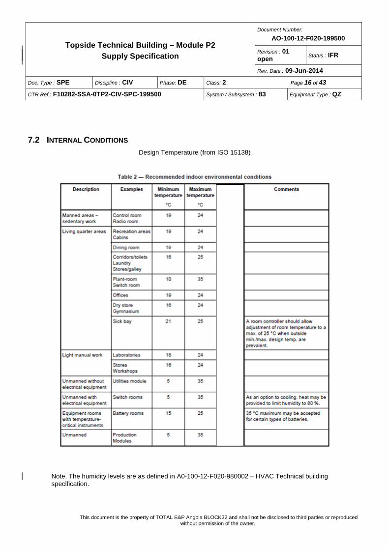
7.2 INTERNAL CONDITIONS Design Temperature (from ISO 15138)
Note. The humidity levels are as defined in A0-100-12-F020-980002 – HVAC Technical building specification.
Topside Technical Building – Module P2 Supply Specification
Document Number:
AO-100-12-F020-199500
Revision : 01 open Status : IFR
Rev. Date : 09-Jun-2014
Doc. Type : SPE Discipline : CIV Phase: DE Class: 2 Page 17 of 43
CTR Ref.: F10282-SSA-0TP2-CIV-SPC-199500 System / Subsystem : 83 Equipment Type : QZ
This document is the property of TOTAL E&P Angola BLOCK32 and shall not be disclosed to third parties or reproduced without permission of the owner.
7.3 PRESSURIZATION The different room of the topsides technical building shall be over-pressurised to 30 Pa. This pressure shall be controlled by the HVAC system. All entrance doors shall be equipped with pressurised airlocks (50 Pa). The pressurization shall be maintained by the emergency HVAC System.
In the laboratory, the office room shall be maintained at a relative positive pressure (50 Pa) with respect to the adjacent testing room (30 Pa) to avoid gas ingress from the testing room.
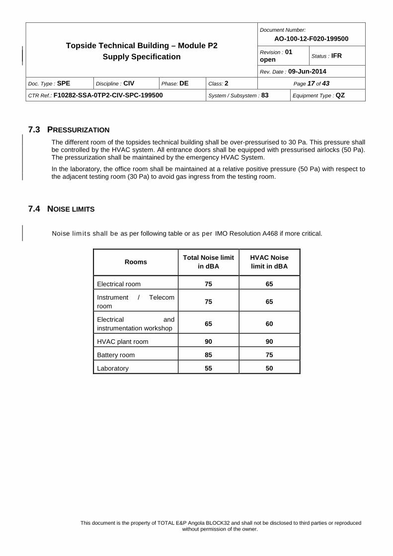
7.4 NOISE LIMITS
Noise limits shall be as per following table or as per IMO Resolution A468 if more critical.
Rooms Total Noise limit in dBA
HVAC Noise limit in dBA
Electrical room 75 65
Instrument / Telecom room 75 65
Electrical and instrumentation workshop 65 60
HVAC plant room 90 90
Battery room 85 75
Laboratory 55 50
Topside Technical Building – Module P2 Supply Specification
Document Number:
AO-100-12-F020-199500
Revision : 01 open Status : IFR
Rev. Date : 09-Jun-2014
Doc. Type : SPE Discipline : CIV Phase: DE Class: 2 Page 18 of 43
CTR Ref.: F10282-SSA-0TP2-CIV-SPC-199500 System / Subsystem : 83 Equipment Type : QZ
This document is the property of TOTAL E&P Angola BLOCK32 and shall not be disclosed to third parties or reproduced without permission of the owner.
8 RISK ASSESSMENT
8.1 AREA CLASSIFICATION. Module P2 will be located in Restricted Area. As such all electrical equipment and instruments installed outside, shall be suitable for Zone 1, Gas group IIA, Temperature Class T3.
Hydrocarbon gas detectors (3 off, 2oo3 voting, for each intake) shall be required at all fresh air intakes to activate the FGS in case of gas release from the process area etc. The FGS will then in turn close the gas tight dampers located on the fresh air ductwork so as not to impact on the Topside internal classification (safe area).
The air pressure in the room spaces of the Topside module P2 shall be maintained by means of pressure relief dampers (refer to block diagrams) and will be kept in a slight but continuous positive overpressure with respect to outside : as such they are considered as safe area.
The exception is the Battery Room, which shall be classified Zone 1 due to the potential presence of Hydrogen. This room shall be of a slightly lower pressure relative to the other Topside P2 Module Rooms while higher than atmosphere.
A 3m zone 2 hazardous area is generated by doors and exhaust of the laboratory. Laboratory shall be then ventilated and classified zone 2.
Electrical Equipment inside this room shall comply with Zone 1, Group IIC and Temperature Class T3 requirements (IEC 60079 requirements).
8.2 FIRE RISK ASSESSMENT FOR EXTERNAL BULKHEADS AND DECKS
The presence of electrical and instrumentation switchboards and batteries originates a fire risk from inside the Module P2.
All HVAC penetrations of classified bulkheads and decks shall be of the same standard as that of the bulkhead/wall/deck/floor, including fire certified spools.
Topside Technical Building – Module P2 Supply Specification
Document Number:
AO-100-12-F020-199500
Revision : 01 open Status : IFR
Rev. Date : 09-Jun-2014
Doc. Type : SPE Discipline : CIV Phase: DE Class: 2 Page 19 of 43
CTR Ref.: F10282-SSA-0TP2-CIV-SPC-199500 System / Subsystem : 83 Equipment Type : QZ
This document is the property of TOTAL E&P Angola BLOCK32 and shall not be disclosed to third parties or reproduced without permission of the owner.
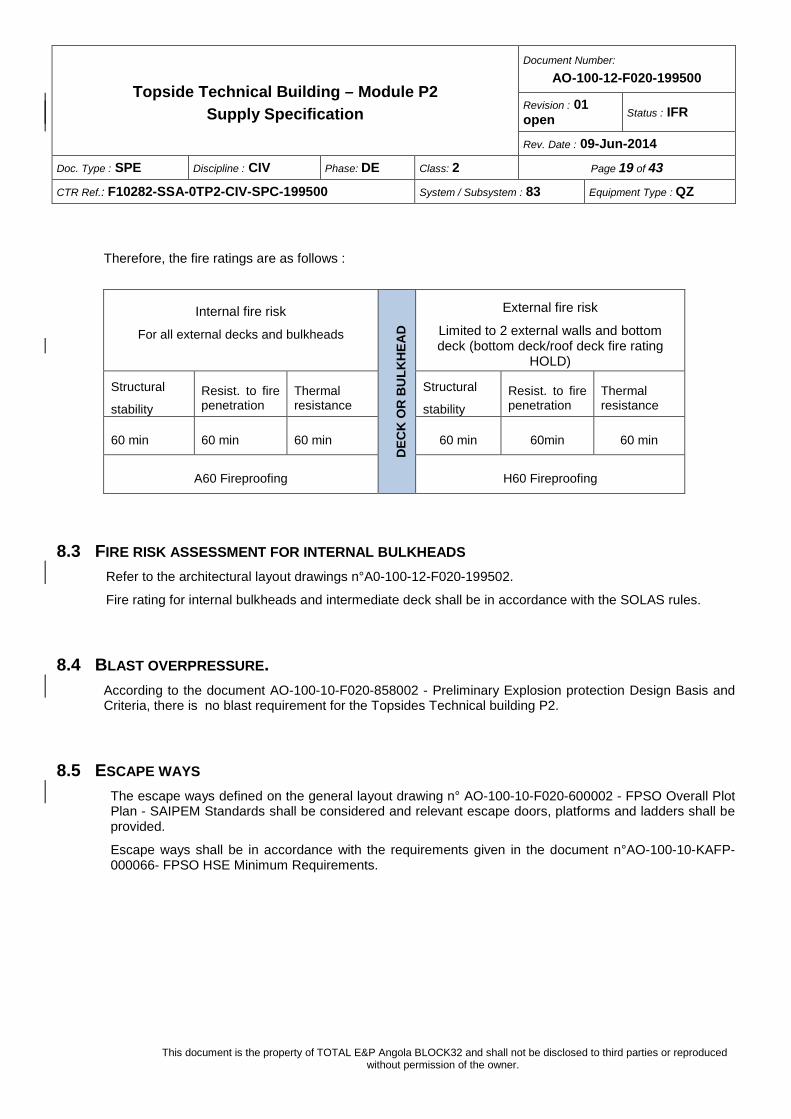
Therefore, the fire ratings are as follows :
Internal fire risk
For all external decks and bulkheads
DEC
K O
R B
ULK
HEA
D
External fire risk
Limited to 2 external walls and bottom deck (bottom deck/roof deck fire rating
HOLD)
Structural
stability Resist. to fire penetration
Thermal resistance
Structural
stability Resist. to fire penetration
Thermal resistance
60 min 60 min 60 min 60 min 60min 60 min
A60 Fireproofing H60 Fireproofing
8.3 FIRE RISK ASSESSMENT FOR INTERNAL BULKHEADS Refer to the architectural layout drawings n°A0-100-12-F020-199502.
Fire rating for internal bulkheads and intermediate deck shall be in accordance with the SOLAS rules.
8.4 BLAST OVERPRESSURE. According to the document AO-100-10-F020-858002 - Preliminary Explosion protection Design Basis and Criteria, there is no blast requirement for the Topsides Technical building P2.
8.5 ESCAPE WAYS The escape ways defined on the general layout drawing n° AO-100-10-F020-600002 - FPSO Overall Plot Plan - SAIPEM Standards shall be considered and relevant escape doors, platforms and ladders shall be provided.
Escape ways shall be in accordance with the requirements given in the document n°AO-100-10-KAFP-000066- FPSO HSE Minimum Requirements.
Topside Technical Building – Module P2 Supply Specification
Document Number:
AO-100-12-F020-199500
Revision : 01 open Status : IFR
Rev. Date : 09-Jun-2014
Doc. Type : SPE Discipline : CIV Phase: DE Class: 2 Page 20 of 43
CTR Ref.: F10282-SSA-0TP2-CIV-SPC-199500 System / Subsystem : 83 Equipment Type : QZ
This document is the property of TOTAL E&P Angola BLOCK32 and shall not be disclosed to third parties or reproduced without permission of the owner.
9 STEEL STRUCTURE The steel structure shall be designed complying with the requirements of the documents :
AO-100-12-F020-110452 - FPSO Topsides structural design basis.
AO-100-12-F020-110455 - FPSO Topsides structural design brief.
The Module P2 shall be able to withstand to a combination of loading during the various stages of load-out, sea transportation, lift installation and operating. In detail: − In place operation − Free area live loads (floors, roof, walkways, stairs, open area, lay-down) − Wind − Lifting − Load out − Sea transportation − Accidental loads (Hull damages, Dropped object, Fire, Flare)
The values of loads to be considered are collected in the above referenced document.
The structural design shall ensure that the structure satisfies the strength and stability requirements when affected by the combination of the above listed loads.
Moreover, fatigue analyses shall ensure that any connection is able to withstand to cyclic loads induced motion (roll, pitch, surge, sway and heave as defined in the Topsides structural design basis), in each phase of life.
The SUBCONTRACTOR shall develop a computer model of the structure and equipment loads to calculate member stresses under various conditions.
The Module P2 will be placed elevated above the main deck of the FPSO. It must be integrated with a structural frame matching with the ship supporting stools, which act as interface points between the ship deck and the Module P2.
The building enclosure shall be air and watertight and shall be capable of maintaining this tightness during and after any transport and/or lifting operations. Welding shall be therefore 100% continuous.
Minimum steel thickness (for structural members ):
6 mm elements belonging to the module primary structure
5 mm for secondary members
Rain hoods are to be provided above doors.
Handrails, staircases, ladders and other ancillaries structures shall be designed and manufactured complying with the CONTRACTOR standards.
Topside Technical Building – Module P2 Supply Specification
Document Number:
AO-100-12-F020-199500
Revision : 01 open Status : IFR
Rev. Date : 09-Jun-2014
Doc. Type : SPE Discipline : CIV Phase: DE Class: 2 Page 21 of 43
CTR Ref.: F10282-SSA-0TP2-CIV-SPC-199500 System / Subsystem : 83 Equipment Type : QZ
This document is the property of TOTAL E&P Angola BLOCK32 and shall not be disclosed to third parties or reproduced without permission of the owner.
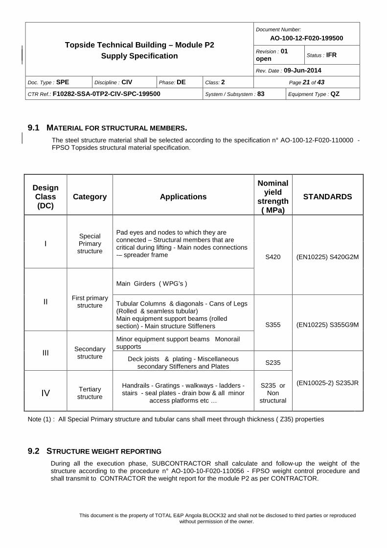
9.1 MATERIAL FOR STRUCTURAL MEMBERS. The steel structure material shall be selected according to the specification n° AO-100-12-F020-110000 - FPSO Topsides structural material specification.
Design Class (DC)
Category Applications Nominal
yield strength ( MPa)
STANDARDS
I Special Primary structure
Pad eyes and nodes to which they are connected – Structural members that are critical during lifting - Main nodes connections -– spreader frame S420 (EN10225) S420G2M
II First primary structure
Main Girders ( WPG’s )
Tubular Columns & diagonals - Cans of Legs (Rolled & seamless tubular) Main equipment support beams (rolled section) - Main structure Stiffeners S355 (EN10225) S355G9M
III Secondary structure
Minor equipment support beams Monorail supports
Deck joists & plating - Miscellaneous secondary Stiffeners and Plates S235
(EN10025-2) S235JR
IV Tertiary structure
Handrails - Gratings - walkways - ladders - stairs - seal plates - drain bow & all minor
access platforms etc …
S235 or Non
structural
Note (1) : All Special Primary structure and tubular cans shall meet through thickness ( Z35) properties
9.2 STRUCTURE WEIGHT REPORTING During all the execution phase, SUBCONTRACTOR shall calculate and follow-up the weight of the structure according to the procedure n° AO-100-10-F020-110056 - FPSO weight control procedure and shall transmit to CONTRACTOR the weight report for the module P2 as per CONTRACTOR.
Topside Technical Building – Module P2 Supply Specification
Document Number:
AO-100-12-F020-199500
Revision : 01 open Status : IFR
Rev. Date : 09-Jun-2014
Doc. Type : SPE Discipline : CIV Phase: DE Class: 2 Page 22 of 43
CTR Ref.: F10282-SSA-0TP2-CIV-SPC-199500 System / Subsystem : 83 Equipment Type : QZ
This document is the property of TOTAL E&P Angola BLOCK32 and shall not be disclosed to third parties or reproduced without permission of the owner.
9.3 IN PLACE LOADS Refer to AO-100-12-F020-110452 - FPSO Topsides structural design basis.
Topside Technical Building – Module P2 Supply Specification
Document Number:
AO-100-12-F020-199500
Revision : 01 open Status : IFR
Rev. Date : 09-Jun-2014
Doc. Type : SPE Discipline : CIV Phase: DE Class: 2 Page 23 of 43
CTR Ref.: F10282-SSA-0TP2-CIV-SPC-199500 System / Subsystem : 83 Equipment Type : QZ
This document is the property of TOTAL E&P Angola BLOCK32 and shall not be disclosed to third parties or reproduced without permission of the owner.
10 CORROSION PROTECTION
The main scope of corrosion protection is to achieve a 20 years durability of the coatings with a minimum of maintenance repair during the FPSO service.
The requirement for surface preparation, application, and inspection are included in the specification AO-100-10-F020-720100 (Painting Specification).
Note: Gratings, stairs, handrails and associated fasteners shall be hot dipped galvanized.
Topside Technical Building – Module P2 Supply Specification
Document Number:
AO-100-12-F020-199500
Revision : 01 open Status : IFR
Rev. Date : 09-Jun-2014
Doc. Type : SPE Discipline : CIV Phase: DE Class: 2 Page 24 of 43
CTR Ref.: F10282-SSA-0TP2-CIV-SPC-199500 System / Subsystem : 83 Equipment Type : QZ
This document is the property of TOTAL E&P Angola BLOCK32 and shall not be disclosed to third parties or reproduced without permission of the owner.
11 ARCHITECTURAL REQUIREMENTS
11.1 INSULATION – PASSIVE FIRE PROTECTION Marine approved mineral shall be installed in the form of semi-rigid slabs, coupled with reinforced aluminium foils as vapour barrier.
The insulation shall be designed to fulfil at the same time the following goals : passive fireproofing, thermal insulation, acoustic insulation. Thickness and density shall match with the above requirements, whichever is the more stringent.
The mineral panels shall be installed adherent to the steel plates and beams, supported by pins welded to the structure and fastened by washers.
Thermal Insulation.
The following minimum thermal insulation shall be achieved (U-value):
External walls, roof, floors 0.60 W / (m2 °K)
Doors 3.50 W / (m2 °K)
Windows 2.70 W / (m2 °K)
All HVAC calculations are to be based on these values or manufacturer standard if more efficient.
Passive fire protection:
External fire-proofing shall be provided with intumescent painting. Internal fire-proofing for bulkheads and decks (including supporting steel beams) shall be provided through rockwool insulation ; internal steel columns shall be protected where necessary to insure the stability.
Both systems shall be compliant with the fire risk assessments (see section 8.2).
11.2 INTERIOR WALL SYSTEM Any system shall be complied with IMO regulations for non-combustibility and fire-resistance.
The fire class definition of the accommodation partitioning will be in accordance with the SOLAS rules.
All B15 partition shall be high noise- reduction type panel (50 mm minimum thickness).
The lining panelling system shall be robust and offer resistance to damage during erection and in use, and shall be arranged to facilitate local removal of panel sections for maintenance of equipment.
Topside Technical Building – Module P2 Supply Specification
Document Number:
AO-100-12-F020-199500
Revision : 01 open Status : IFR
Rev. Date : 09-Jun-2014
Doc. Type : SPE Discipline : CIV Phase: DE Class: 2 Page 25 of 43
CTR Ref.: F10282-SSA-0TP2-CIV-SPC-199500 System / Subsystem : 83 Equipment Type : QZ
This document is the property of TOTAL E&P Angola BLOCK32 and shall not be disclosed to third parties or reproduced without permission of the owner.
11.3 FINISHING All panels and linings shall be washable and easy to clean without dismantling. All lighting, HVAC outlets, sockets fire detectors, etc. shall be incorporated in the paneling system and shall be flush.
The interior faces of steel bulkheads will be lined with a minimum 0.6 mm perforated painted steel up to 3 meters.
The room spaces paneling requirements shall correspond to the function of the space, refer to the applicable architectural drawings.
11.4 CEILING Interior spaces will receive a free span linear metal ceiling meeting regulatory requirements. Ceiling panels will consist of mineral wool core and will have a decorative facing on the exposed side.
The room spaces ceiling requirements shall correspond to the function of the space, refer to the applicable architectural drawings.
11.5 FLOORS Epoxy resin flooring
All floor areas shall receive epoxy resin flooring except rooms where raised floors are required.
All wet areas shall have epoxy rolled base. All dry areas shall have a 101.6mm (4”) cove base. As a general rule, the smoother and less porous a surface, the easier it is to clean. However, for wet purpose applications, the surface must be textured. Such texturing can be achieved by selective grading of aggregates, or by sandwiching special high abrasion resistant aggregate between the surface coatings of clear or pigmented resins. The degree of contaminant build-up on the floor will be dictated by the coarseness.
Epoxy resin floors shall be designed for heavy duty, extreme durability and easy maintenance. The surface shall be anti-slip type.
Battery, HVAC room and laboratory shall be considered as “wet rooms” and shall be complete with bounding coating, where the resin floor will be rounded. The lining or the partition panel shall be erected accordingly. The battery room flooring shall be acid resistant and sealed to avoid spillage.
The epoxy resin floor of both rooms shall be sloped towards the scuppers (slope not lower than 3 /1000), with appropriate traps fitted as necessary.
The HVAC Plant Room shall have a floor drains fitted as to aid cleaning and possible leakage from the chilled water system, this is to have a sump / u trap sized correctly as to prevent the loss of Topside pressurisation and cross contamination of smells.
Floor coamings below the HVAC equipment shall be provided to contain any unexpected spillage.
Air Handling Units condensate drains shall be fitted with appropriate manometric traps.
The siphons of HVAC room gutters shall be calculated to suit room space overpressure, in order to prevent the Module losing the air tightness.
The Battery Room scuppers shall be connected to a drain system down to the Module bottom, where a lockable valve shall be provided. It shall be kept normally closed, in order to prevent the Module losing the air tightness.
Topside Technical Building – Module P2 Supply Specification
Document Number:
AO-100-12-F020-199500
Revision : 01 open Status : IFR
Rev. Date : 09-Jun-2014
Doc. Type : SPE Discipline : CIV Phase: DE Class: 2 Page 26 of 43
CTR Ref.: F10282-SSA-0TP2-CIV-SPC-199500 System / Subsystem : 83 Equipment Type : QZ
This document is the property of TOTAL E&P Angola BLOCK32 and shall not be disclosed to third parties or reproduced without permission of the owner.
The colour shall be selected from the Standard Colour Card, in compliance with CONTRACTOR requirement.
Raised floors
The following rooms shall be provided with raised floors: − Electrical Room − Instrumentation and telecom room − Instrumentation / Telecom Workshop
In any case, the material shall be in compliance to IMO Resolution A 653 (16).
The floor voids shall be dedicated for each room and not as a common floor void per level (as per NFPA) ; thus room partitions / room boundaries shall be from deck to deck.
The raised floor shall be composed of a fixed adjustable supporting structure with removable tiles.
Perforated ventilation tiles shall be installed in the raised floor as to aid ventilation and cooling of the associated room.
The supporting structure of electrical and instrumentation panels, made of painted carbon steel beams, legs and wind-bracings, shall be designed for supporting also the surrounding removable tiles. Switchboards, Instrument Panels shall be situated on metallic base frames fastened to the floor, as per manufacturers recommendations.
The free space under the raised floor shall be 1000 mm.
A fireproof gasket shall be placed between the supporting structure and the removable tiles, with the scope of soundproofing and air-dust sealing
Tiles shall be: − 600 mm x 600 mm − Fire retardant with a self-extinguishing covering material − Resisting distributed loads of 500 kg/m2 − Resisting concentrated loads : 280 kg (centre of the panel) − Top finish : vinyl, min. 2 mm
11.6 DOORS The quantities and locations of doors shall be as indicated on the building arrangement drawings.
The doors of Module P2 shall be fire rated according to the bulkheads where they are to be installed. They shall match internationally recognised standards and meet offshore environment and service conditions.
The characteristics of every door shall comply with SOLAS requirements. Fireproofing doors shall be provided with Type Approval Certifications issued a Notified Body, belonging to IACS (International Association of Classification Societies).
External doors shall always open outwards and in the direction of the escape route.
All main entrances shall have airlocks with adequately separated doors to control the indoor temperature and to prevent gas ingress.
Topside Technical Building – Module P2 Supply Specification
Document Number:
AO-100-12-F020-199500
Revision : 01 open Status : IFR
Rev. Date : 09-Jun-2014
Doc. Type : SPE Discipline : CIV Phase: DE Class: 2 Page 27 of 43
CTR Ref.: F10282-SSA-0TP2-CIV-SPC-199500 System / Subsystem : 83 Equipment Type : QZ
This document is the property of TOTAL E&P Angola BLOCK32 and shall not be disclosed to third parties or reproduced without permission of the owner.
Where visibility is required, doors shall be complete with a vision panel, fire and blast rated to suit the door rating.
All doors shall be supplied with key lock, complete with 3 keys. 3 master keys shall be also supplied.
11.6.1 External A60/H60 doors Heavy duty hinged offshore doors shall be supplied and installed on the external walls, with the following main features: − A60 / H60 fireproofing (complying with risk assessment) − Gas tight criteria as per specification n°AO-100-10-F020-970006 - HVAC basis of design
Main features : − Door leaf and frame in carbon steel primed and painted − Core material : ceramic fibre or rockwool (depending on manufacturer approved standard) − Frame for being welded or bolted − Stainless steel threshold elevated from the tread − Sound reduction: 40dB − AISI 316 stainless steel hinges, handle and lock case − N° 3 hinges − Gasket in frame − “Marine” class hydraulic door closer − Vision panel − Anti-panic locks which can be locked by key from the outside and unlocked by the anti-panic bar from
the inside − SS nameplate
11.6.2 Internal A60 doors Internal A60 doors shall be gas tight (same criteria as external doors).
Medium duty A-60 hinged offshore doors shall be supplied and installed on internal walls, with the following main features : − Door leaf and frame in mild steel primed and painted − Core material: ceramic fibre or rockwool (depending on manufacturer approved standard) − Frame for being welded or bolted − Gasket in frame − AISI 316 stainless steel threshold elevated from the tread − Sound reduction: 38 dB − Stainless steel offshore hinges, handle and lock case − N° 3 hinges − “Marine” class hydraulic door closer − Vision panel − Anti-panic locks
Topside Technical Building – Module P2 Supply Specification
Document Number:
AO-100-12-F020-199500
Revision : 01 open Status : IFR
Rev. Date : 09-Jun-2014
Doc. Type : SPE Discipline : CIV Phase: DE Class: 2 Page 28 of 43
CTR Ref.: F10282-SSA-0TP2-CIV-SPC-199500 System / Subsystem : 83 Equipment Type : QZ
This document is the property of TOTAL E&P Angola BLOCK32 and shall not be disclosed to third parties or reproduced without permission of the owner.
− Plastic nameplate
11.7 FURNISHING Generally speaking, the furniture shall be covered with fire retardant plastic laminate, chairs shall be manufactured with self-extinguishing padding and fabric.
Refer AO-100-12-F020-199502 Topside Technical Building Module P2 - Architectural layout for furniture and equipment to be supplied.
Topside Technical Building – Module P2 Supply Specification
Document Number:
AO-100-12-F020-199500
Revision : 01 open Status : IFR
Rev. Date : 09-Jun-2014
Doc. Type : SPE Discipline : CIV Phase: DE Class: 2 Page 29 of 43
CTR Ref.: F10282-SSA-0TP2-CIV-SPC-199500 System / Subsystem : 83 Equipment Type : QZ
This document is the property of TOTAL E&P Angola BLOCK32 and shall not be disclosed to third parties or reproduced without permission of the owner.
12 HVAC SYSTEM
The HVAC systems of Module P2 is fully described in the following project documents :
A0-100-12-F020-980002 HVAC Technical Building P2 specification
A0-100-12-F020-980001 HVAC D&ID Technical Building P2
A0-100-12-F020-980003 HVAC Technical Building P2 - Equipment Specification
The cooling system will be chilled water system, from a packaged water cooled condensing units, in the HVAC plant room with an external air cooled dry coolers.
The central air conditioning plant air handling unit is to be designed and sized for the fresh air, internal heat balance and pressurization requirements, this system will include the cooling capacity for all general areas.
The Module P2 shall be supplied with a complete HVAC system including all ductwork, dampers, controls and all other accessories necessary for a fully functional system, with central plant HVAC units which will consist of:
- 2 x 100% capacity skid mounted water cooled condensing units connected by chilled water pipework to the AHU
- 2 x 100% capacity air cooled dry cooler
- 2 x 100% capacity E & I rooms Air Handling Units with centrifugal fan, mixing chamber, 2 stage filtration and chilled water supplied cooling coils
- 7 duct mounted electrical heaters
- 2 x 100% capacity extract fans for Battery room
- 2 x 100% capacity extract fans for Laboratory
- 2 x 100% capacity extract fans for HVAC room which will run in case of refrigerant leak detection, in compliance with EN 378 part 3
The design of the units is to allow maintenance access of the standby unit, while the duty unit is running, in a safe manner.
The main system will be controlled by a specific HVAC control panel using a PLC based control system.
The central plant will utilise the return air from the system to reduce the cooling capacity required, only clean and non-polluted air from the general areas shall be returned. The basis for this mixing of fresh and return air will be by psychometric analysis. The system unit capacity will be based on supplying the total volume of fresh air, make up air, and overpressure requirements for all areas in addition to the cooling and environmental requirements of the other areas.
The HVAC equipment shall be designed for corrosive environment and marine condition.
Topside Technical Building – Module P2 Supply Specification
Document Number:
AO-100-12-F020-199500
Revision : 01 open Status : IFR
Rev. Date : 09-Jun-2014
Doc. Type : SPE Discipline : CIV Phase: DE Class: 2 Page 30 of 43
CTR Ref.: F10282-SSA-0TP2-CIV-SPC-199500 System / Subsystem : 83 Equipment Type : QZ
This document is the property of TOTAL E&P Angola BLOCK32 and shall not be disclosed to third parties or reproduced without permission of the owner.
The units proposed are to be selected based on the most efficient, in terms of capacity, absorbed electrical power and unit physical dimension.
As the building is partly or fully located within hazardous Restricted Areas, it will be pressurized to maintain an unclassified safe area inside.
Building pressurization shall be in compliance with the requirements of the FPSO HSE Minimum Requirements.
Pressurization will be supplied by the HVAC air conditioning system Air Handling Units.
The HVAC system supplied pressurization shall provide a positive pressure of 50Pa with the doors closed. Excess air shall be relieved by means of appropriate pressurization relief dampers.
In accordance with NFPA requirements a dedicated alarm for remote indication of pressurization loss and a local indication on the panel shall be provided, the alarm will have a user adjustable time delay (15 second to 1 minute) to allow normal access and egress to the building.
Potable water and service air supply shall be provided within the HVAC room.
Topside Technical Building – Module P2 Supply Specification
Document Number:
AO-100-12-F020-199500
Revision : 01 open Status : IFR
Rev. Date : 09-Jun-2014
Doc. Type : SPE Discipline : CIV Phase: DE Class: 2 Page 31 of 43
CTR Ref.: F10282-SSA-0TP2-CIV-SPC-199500 System / Subsystem : 83 Equipment Type : QZ
This document is the property of TOTAL E&P Angola BLOCK32 and shall not be disclosed to third parties or reproduced without permission of the owner.
13 ELECTRICAL SYSTEM
13.1 LIGHTING The Module P2 shall be complete with all necessary lighting (including exit lights) and small power systems, including Local Distribution Panel, lighting fixtures, switches, socket outlets, cables, cable trays and accessories.
Rooms lighting shall be as per specification n°AO-100-10-F020-410000 – Electrical Design criteria
Lighting for external walkways, staircases, roof mounted equipment etc. shall also be included in the SUBCONTRACTOR scope (design, supply, construction and installation).
The lighting system shall be split into two main systems: − Essential system: fed from essential distribution boards. − Emergency system: fed from emergency network. At least one third of the lighting fixture supplied from
a dedicated essential supply. These lights illuminate also escape routes, emergency exits and ladders. They shall have an integrated battery (90 minutes autonomy) and shall be ATEX certified category 2G.
External lighting fixtures shall be high pressure sodium or fluorescent lamps. suitable for Zone 1, Gas group IIA, Temperature Class T3.
Battery room lighting shall be suitable for Zone 1, Gas group IIC, Temperature Class T3.
Internal lighting fixtures shall be controlled by switches located at any entrance door. No outdoor lighting switches shall be provided.
13.2 SOCKET OUTLETS Socket outlets installed inside technical rooms shall be of Industrial type IK08 with cover. Degree of protection provided by enclosure : IP22.
All external sockets shall be provided with plugs. Degree of protection provided by enclosure : IP56.
13.2.1 Welding sockets Welding sockets are not required for the module P2.
13.2.2 Convenience sockets Socket outlets 16A (2P+E) shall be provided in each room.
Convenience sockets installed indoor will be supplied as follows: − Essential 220 V, 2 phases + earth 16A − UPS 230 V 2 phases + earth 16A
Topside Technical Building – Module P2 Supply Specification
Document Number:
AO-100-12-F020-199500
Revision : 01 open Status : IFR
Rev. Date : 09-Jun-2014
Doc. Type : SPE Discipline : CIV Phase: DE Class: 2 Page 32 of 43
CTR Ref.: F10282-SSA-0TP2-CIV-SPC-199500 System / Subsystem : 83 Equipment Type : QZ
This document is the property of TOTAL E&P Angola BLOCK32 and shall not be disclosed to third parties or reproduced without permission of the owner.
Convenience socket outlets circuits shall not be mixed with lighting circuit.
As a minimum and unless otherwise specified, the following number of UPS socket shall be installed: − 2 UPS sockets in electrical room − 1 UPS socket in the E&I workshop − 2 UPS sockets in laboratory − 4 UPS sockets in Instrument & Telecom room
13.3 CABLES All cables shall be flame retardant type to IEC 60332-3-22, Category A and Low Smoke, complying with IEC 60332.
In addition to this requirement, cables for special (vital safety) services (ICSS including F&G detection, Inergen fire extinguishing system, PA/GA...) shall also be fire resistant type to IEC 60331-21 and compliant with HSE Minimum Requirements.
Cables associated with electrical power for HVAC systems shall be as per electrical Specification, all other HVAC system cables shall be as per instrument Specification.
Cable cross sections shall be chosen among the standardised list of IEC 60228.
As a general rule, cables shall be armoured in the following cases: − Cables running in hazardous areas in zone 1 & 2 − Fire resisting cables
Unless otherwise specified, mixing of two different voltages (level & source) in the same cable is forbidden.
13.4 CABLE ROUTING AND CABLE SEGREGATION Cable trays/ladders systems shall be of the following types: − Outdoor : stainless steel suitable for marine environment − Indoor : Same as outdoor or hot dip galvanised steel
A minimum of 20% spare capacity in each cable ladder/tray shall be provided for future extension.
Cable ladder/tray shall be bolted or clamped to supports. Supports shall be welded to the structure. The ends of cable trays shall be finished in such a way as to avoid damage to the cable sheaths.
Joints in rack and tray shall be electrically bonded using the SUBCONTRACTOR’s straps. To avoid adverse chemical galvanic reaction, nylon insulating pads shall be installed wherever dissimilar metals come into contact.
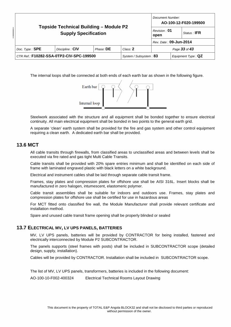
13.5 EARTHING The equipotential earth bonding system shall comprise internal loops and a general earth grid, connected at least in two opposite points. These two links shall have the same cross-sectional area as that of the cable to which they are connected. The minimum equivalent cross-sectional area of these links shall be 70 mm2 Cu.
The general earth grid and internal loops shall comprise class 2 bare copper conductors with a cross-sectional area calculated in accordance with section 543.1.1 of IEC 60364.5.54.
Topside Technical Building – Module P2 Supply Specification
Document Number:
AO-100-12-F020-199500
Revision : 01 open Status : IFR
Rev. Date : 09-Jun-2014
Doc. Type : SPE Discipline : CIV Phase: DE Class: 2 Page 33 of 43
CTR Ref.: F10282-SSA-0TP2-CIV-SPC-199500 System / Subsystem : 83 Equipment Type : QZ
This document is the property of TOTAL E&P Angola BLOCK32 and shall not be disclosed to third parties or reproduced without permission of the owner.
The internal loops shall be connected at both ends of each earth bar as shown in the following figure.
Steelwork associated with the structure and all equipment shall be bonded together to ensure electrical continuity. All main electrical equipment shall be bonded in two points to the general earth grid.
A separate ‘clean’ earth system shall be provided for the fire and gas system and other control equipment requiring a clean earth. A dedicated earth bar shall be provided.
13.6 MCT All cable transits through firewalls, from classified areas to unclassified areas and between levels shall be executed via fire rated and gas tight Multi Cable Transits.
Cable transits shall be provided with 20% spare entries minimum and shall be identified on each side of frame with laminated engraved plastic with black letters on a white background.
Electrical and instrument cables shall be laid through separate cable transit frame.
Frames, stay plates and compression plates for offshore use shall be AISI 316L. Insert blocks shall be manufactured in zero halogen, intumescent, elastomeric polymer.
Cable transit assemblies shall be suitable for indoors and outdoors use. Frames, stay plates and compression plates for offshore use shall be certified for use in hazardous areas
For MCT fitted onto classified fire wall, the Module Manufacturer shall provide relevant certificate and installation method.
Spare and unused cable transit frame opening shall be properly blinded or sealed
13.7 ELECTRICAL MV, LV UPS PANELS, BATTERIES MV, LV UPS panels, batteries will be provided by CONTRACTOR for being installed, fastened and electrically interconnected by Module P2 SUBCONTRACTOR.
The panels supports (steel frames with posts) shall be included in SUBCONTRACTOR scope (detailed design, supply, installation).
Cables will be provided by CONTRACTOR. Installation shall be included in SUBCONTRACTOR scope.
The list of MV, LV UPS panels, transformers, batteries is included in the following document:
AO-100-10-F002-400324 Electrical Technical Rooms Layout Drawing
Topside Technical Building – Module P2 Supply Specification
Document Number:
AO-100-12-F020-199500
Revision : 01 open Status : IFR
Rev. Date : 09-Jun-2014
Doc. Type : SPE Discipline : CIV Phase: DE Class: 2 Page 34 of 43
CTR Ref.: F10282-SSA-0TP2-CIV-SPC-199500 System / Subsystem : 83 Equipment Type : QZ
This document is the property of TOTAL E&P Angola BLOCK32 and shall not be disclosed to third parties or reproduced without permission of the owner.
13.8 TRANSFORMERS ON ROOF Transformers will be provided by CONTRACTOR for being installed on the roof, fastened and electrically interconnected by Module P2 SUBCONTRACTOR.
The transformers shall be covered by a steel shelter, separated by fire walls and provided with hauling device.
An access platform for transformers maintenance is provided around the transformers (~ +1.00m above the roof).
An oil collecting system (drip pan) shall be provided to collect the transformers oil spillage with connection to the open drain at the bottom of Module P2.
The transformers are handled on the roof with a hauling system up to the portside of the module and then picked up by the main crane. The transformers rails and hauling devices shall be supplied by the SUBCONTRACTOR.
Moreover, a portion (refer to architectural layout) of the roof shall be designed for the drop object constraint.
The design criteria for the drop object load case are : - Total load 3000 kg on 4 impacts (2.60m x 3.00m) on the edge grid - Drop height : 1.00m - Safety coefficient : = 2
13.9 ELECTRICAL SAFETY KIT An electrical safety kit shall be provided in the Electrical Room including stool, voltage detector, pole, gloves, shoes, mobile earthing kit with clamps, warning and first-aid posters, rechargeable portable lighting suitable for hazardous areas, insulation mat, etc.
Topside Technical Building – Module P2 Supply Specification
Document Number:
AO-100-12-F020-199500
Revision : 01 open Status : IFR
Rev. Date : 09-Jun-2014
Doc. Type : SPE Discipline : CIV Phase: DE Class: 2 Page 35 of 43
CTR Ref.: F10282-SSA-0TP2-CIV-SPC-199500 System / Subsystem : 83 Equipment Type : QZ
This document is the property of TOTAL E&P Angola BLOCK32 and shall not be disclosed to third parties or reproduced without permission of the owner.
14 TELECOM AND INSTRUMENT SYSTEMS
14.1 INSTRUMENTATION PANELS Instrumentation panels (UCP and ICSS panels) and their supports will be provided and installed by CONTRACTOR once the module P2 will be offloaded and installed on the FPSO.
Instrument cables will also be provided and installed by CONTRACTOR.
Therefore, the instrumentation room shall be delivered with the raised floor with openings suiting with the instruments cabinets layout ; this layout will be addressed by CONTRACTOR to SUBCONTRACTOR for the detail engineering.
14.2 TELEPHONE AND DATA SYSTEMS The following telecom equipment will be supplied by CONTRACTOR as free issue items and shall be installed by SUBCONTRACTOR in Module P2 :
- Telephone network
- IT and data network for files management, email, etc.
- 1 data network and telephone distribution cabinet
- Communication, control and power cables
14.3 PA/GA SYSTEM The following internal loudspeakers for General Alarm and Public Address will be supplied by CONTRACTOR as free issue items and shall be installed by SUBCONTRACTOR in Module P2 :
- N° 4 PA/GA Main equipment Cabinets
- N° 20 internal loudspeakers
- Communication, control and power cables
14.4 ACCESS CONTROL AND POB SYSTEM An access control system for controlling personnel entry/exit in P2 Module will be supplied by CONTRACTOR as free issue item and shall be installed by SUBCONTRACTOR in P2 Module. It will be composed of:
- central unit
- badge reader for main entry doors
- door lock equipment for main entry doors
- exit pushbutton for each main doors
- 1 Access Control and POB system Main equipment cabinet

Topside Technical Building – Module P2 Supply Specification
Document Number:
AO-100-12-F020-199500
Revision : 01 open Status : IFR
Rev. Date : 09-Jun-2014
Doc. Type : SPE Discipline : CIV Phase: DE Class: 2 Page 36 of 43
CTR Ref.: F10282-SSA-0TP2-CIV-SPC-199500 System / Subsystem : 83 Equipment Type : QZ
This document is the property of TOTAL E&P Angola BLOCK32 and shall not be disclosed to third parties or reproduced without permission of the owner.
- Communication, control and power cables
Topside Technical Building – Module P2 Supply Specification
Document Number:
AO-100-12-F020-199500
Revision : 01 open Status : IFR
Rev. Date : 09-Jun-2014
Doc. Type : SPE Discipline : CIV Phase: DE Class: 2 Page 37 of 43
CTR Ref.: F10282-SSA-0TP2-CIV-SPC-199500 System / Subsystem : 83 Equipment Type : QZ
This document is the property of TOTAL E&P Angola BLOCK32 and shall not be disclosed to third parties or reproduced without permission of the owner.
15 FIRE AND GAS SYSTEM The F&G system will be supplied according to the document A0-100-10-F020-853000 - Fire and Gas Detection Philosophy.
The following detectors will be provided :
• Optical Smoke detectors in the different rooms (except laboratory); raised floors and airlocks.
• In-duct smoke detection shall be installed in the extract air ducting of battery rooms.
• High Sensitive Smoke Detection (HSSD) shall be supplied and installed (by CONTRACTOR) as follows :
- in the electrical room and in the instrumentation/telecom room and associated voids (raised floor space)
- for monitoring the FGS, ESD, UPS cabinets
• ROR heat detection shall be installed in the laboratory.
• Fusible loops shall be installed in each transformer.
• Flammable gas detectors shall be located in:
- in the airlocks of E&I buildings;
- in the laboratory and “critical” rooms: IT room; HVAC room and battery room (Hydrogen gas detectors shall be provided each battery room where batteries are of vented nickel-cadmium type)
• HVAC inlet gas detectors
Addressable fire detection system is not accepted for the E&I buildings.
Therefore, gas / fire / smoke / heat detectors / MAC installed in E&I buildings shall be directly connected to the FGS cabinets.
In order to limit the number of I/O’s, these smoke and heat detectors can be grouped and connected in several loops.
MAC can be connected to each other in series by fire area.
In addition, Fire and gas sensors and final elements installed outdoor shall be certified ATEX for use in Zone 1 Gas Group IIA IICA and Temperature Class T3.
Electrical cables for F&G system shall be Fire Resistant type, complying with IEC 60331.
In false floor of the instrumentation and telecom room the instrument cables will run in bundles without cable trays except for network cable, telecom, optic fibre and for cables which are a voltage higher or equal to 400 V.
Cable trays shall be galvanized carbon steel for inside, AISI 316L SS or GRP cable trays with corrosion proof supports and bolting for outside.
Topside Technical Building – Module P2 Supply Specification
Document Number:
AO-100-12-F020-199500
Revision : 01 open Status : IFR
Rev. Date : 09-Jun-2014
Doc. Type : SPE Discipline : CIV Phase: DE Class: 2 Page 38 of 43
CTR Ref.: F10282-SSA-0TP2-CIV-SPC-199500 System / Subsystem : 83 Equipment Type : QZ
This document is the property of TOTAL E&P Angola BLOCK32 and shall not be disclosed to third parties or reproduced without permission of the owner.
For Instrument and Telecom cables, the use of MCT is not mandatory. The cables crossing construction walls could be sealed with caulk which provides a firm but flexible seal for fire rated structure.
Topside Technical Building – Module P2 Supply Specification
Document Number:
AO-100-12-F020-199500
Revision : 01 open Status : IFR
Rev. Date : 09-Jun-2014
Doc. Type : SPE Discipline : CIV Phase: DE Class: 2 Page 39 of 43
CTR Ref.: F10282-SSA-0TP2-CIV-SPC-199500 System / Subsystem : 83 Equipment Type : QZ
This document is the property of TOTAL E&P Angola BLOCK32 and shall not be disclosed to third parties or reproduced without permission of the owner.
16 ACTIVE FIRE PROTECTION The active fire protection in the module P2 is ensured through the following systems :
- Fire water hose reels shall be provided as per HSE requirements and specification n°AO-100-10-F020-852000 - Active Fire Protection philosophy.
- Portable fire extinguishers shall be supplied, installed and wall fastened, complying with NFPA 10 and NFPA 12.
They shall be located close to the main access doors and close to the emergency exits, following the instructions of CONTRACTOR.
- Clean agent protection will be provided in the raised floor of the electrical room and instrumentation room. The clean agent will be Inergen ; the gas cylinders will be stored on the roof and protected by a shelter.
Topside Technical Building – Module P2 Supply Specification
Document Number:
AO-100-12-F020-199500
Revision : 01 open Status : IFR
Rev. Date : 09-Jun-2014
Doc. Type : SPE Discipline : CIV Phase: DE Class: 2 Page 40 of 43
CTR Ref.: F10282-SSA-0TP2-CIV-SPC-199500 System / Subsystem : 83 Equipment Type : QZ
This document is the property of TOTAL E&P Angola BLOCK32 and shall not be disclosed to third parties or reproduced without permission of the owner.
17 COMPRESSED AIR SYSTEM Compressed (service) air and instrument air networks shall be designed, supplied and installed by the SUBCONTRACTOR for the facilities installed in the Module P2 :
- HVAC room
- E&I workshop
- Laboratory
The system shall have interface point to connect with the FPSO compressed air and instrument air networks, at the Module base.
Tubing, fitting and accessories shall be stainless steel 316L.
Topside Technical Building – Module P2 Supply Specification
Document Number:
AO-100-12-F020-199500
Revision : 01 open Status : IFR
Rev. Date : 09-Jun-2014
Doc. Type : SPE Discipline : CIV Phase: DE Class: 2 Page 41 of 43
CTR Ref.: F10282-SSA-0TP2-CIV-SPC-199500 System / Subsystem : 83 Equipment Type : QZ
This document is the property of TOTAL E&P Angola BLOCK32 and shall not be disclosed to third parties or reproduced without permission of the owner.
18 LABORATORY
The Laboratory shall be provided (detailed engineering, supply and installation by SUBCONTRACTOR) with the following equipment :
- Furniture : all work benches, extraction hoods, plumbing, drainage, sampling pipework, lights, internal gas detectors where required. This includes :
o Gas cylinders for the following gas : Hydrogen, Air, Helium
o Instrument air supply
o Nitrogen supply
o Potable water supply
o Hot water production
o 1 hood for each chromatograph with a common extraction.
o 1 Desk and 1 chair
- 4 fume cupboard extraction systems (1 x 100% ATEX fan for each system)
- 1 safety shower
- Eye wash (number to be confirmed)
All equipment shall complies to EN Laboratory EN 14175 or equivalent.
For HVAC in the laboratory refer to section 12 and referenced HVAC project documents..
Topside Technical Building – Module P2 Supply Specification
Document Number:
AO-100-12-F020-199500
Revision : 01 open Status : IFR
Rev. Date : 09-Jun-2014
Doc. Type : SPE Discipline : CIV Phase: DE Class: 2 Page 42 of 43
CTR Ref.: F10282-SSA-0TP2-CIV-SPC-199500 System / Subsystem : 83 Equipment Type : QZ
This document is the property of TOTAL E&P Angola BLOCK32 and shall not be disclosed to third parties or reproduced without permission of the owner.
19 ELECTRICAL AND INSTRUMENTATION WORKSHOP
The E&I workshop shall be provided (detailed engineering, supply and installation by SUBCONTRACTOR) with the following equipment :
- Furniture : all work benches, plumbing, drainage, lights, sockets, internal gas detectors where required.
- Instrument air supply
- Desk and chair
Topside Technical Building – Module P2 Supply Specification
Document Number:
AO-100-12-F020-199500
Revision : 01 open Status : IFR
Rev. Date : 09-Jun-2014
Doc. Type : SPE Discipline : CIV Phase: DE Class: 2 Page 43 of 43
CTR Ref.: F10282-SSA-0TP2-CIV-SPC-199500 System / Subsystem : 83 Equipment Type : QZ
This document is the property of TOTAL E&P Angola BLOCK32 and shall not be disclosed to third parties or reproduced without permission of the owner.
20 MISCELLANEOUS
The following equipment will be supplied and installed: − Safety signs and labels – in double language English / Portuguese shall be supplied and installed,
according with ISO 3864 parts I & III, ISO 7010 and ISO 14726. − Air breathing apparatus including air storage cylinders, breathing air panel, purge air panel, distribution
system and nozzles, mask and protection kit, electrical and instrumental system and accessories. − Defibrillator − 1 eye bath inside battery rooms. − 2 lifting devices for batteries handling – capacity 500kg (to be confirmed) − 1 boom rest on roof for crane arm − External protection of the bulkhead on portside, to prevent any lateral impact from crane load.