aopa’s prosthetic foot project - american orthotic and prosthetic · pdf...
TRANSCRIPT

AOPA’S PROSTHETIC FOOT PROJECT What It Is, What It Is Not, and What Patient Care Facility Providers/Practitioners Need to Know…
Dear AOPA Members:
We would like to take this opportunity to bring you up-to-date on the status of the AOPA Prosthetic Foot Project.
What It Is…This project, which was begun in 2007 at the behest of the SADMERC, had as one of its goals to improve the
accuracy and consistency of the coding of prosthetic feet through the development of standard tests that would
validate the existence of certain features of a foot. The participating foot manufacturers provided the engineering
input and assistance that allowed such tests to be created and subsequently carried out on a number of existing
feet. Based upon the results of these tests, these feet were then categorized into specific recommended HCPCS
codes. The second goal of the project was to deliver these results to Medicare in the hope that it would adopt
these coding recommendations and the accompanying testing methodology.
What It Is Not…At no time during this project did AOPA ever intend to develop clinical standards of care for these feet. The
project’s findings relate only to appropriate coding and do not speak to what foot is most clinically appropriate
for a particular patient.
Also, at this time, this is a report/proposal from AOPA to CMS, nothing more and nothing less. AOPA is NOT
recommending that clinicians should use these recommended code descriptors and assignments for your
current coding. AOPA is informing everyone that at this point no one at CMS has given any indication whether
the agency will agree with any, some or all of these recommendations in the report. It could be perilous for
practitioners/patient care facility owners to misunderstand this, or to believe that this document comprises
recommendations on coding that have been endorsed by either AOPA or CMS for purposes of coding TODAY.
What Patient Care Facility Providers/Practitioners Need to Know…As we reported during the recent National Assembly in Orlando, the final report has been delivered to CMS and a
face to face meeting is planned, during which AOPA will urge CMS to accept the findings of this report. While we
are hopeful that CMS will accept the report’s findings, there are no guarantees. Therefore, unless and until CMS
formally agrees to adopt these recommendations, they should not be considered as accepted by CMS. As always,
unless these recommendations are adopted and published by CMS, through the PDAC, your choice of appropriate
coding for prosthetic feet remains your decision and responsibility. In addition, if CMS does decide to accept
these findings, it is very unlikely that this action would be retroactive to dates of service prior to its decision.
We hope that you will take a moment to review the full report. We will continue to keep you abreast of new
developments, but if you have any questions, please contact Kathy Dodson at [email protected] or Joe
McTernan at [email protected].


Descriptors, made appropriate revisions and then developed testing mechanisms that would validate each mechanical feature defined in the Descriptors. This same group then carried out product testing. This testing consisted of a “round robin” series of tests where all feet were tested by all manufacturers that had appropriate equipment to carry out such tests. In every case, the same specific foot was tested by all participating testers, through shipping the same device from one manufacturer to another. In addition, all testers used the same protocols, agreed upon by the Workgroup, when developing the testing mechanisms. Once testing was completed, the results allowed the Workgroup to assign specific feet to specific HCPCS codes. Also, participating manufacturers were offered the option to have independent testing done and were invited to sign an acknowledgement regarding their participation in the project (see pages 36 and 38 for a full copy of the acknowledgement and a disclaimer regarding future use of this report). Note: Testing thresholds were established based on mechanical/functional properties of commercially available products at the time of the testing and are not meant to represent clinical or safety standards of individual feet when used for specific patients
Going Forward and Sunset Date Initial testing often yielded the need to revise testing guidelines to accurately measure mechanical features. It is important to note that product testing continues to be refined and the testing guidelines and thresholds are subject to future revision as more data is obtained and new products come on the market. In addition, orthotics and prosthetics is a field where technology and advances in science and technique are relatively frequent. In recognition of this, we are establishing a specific sunset provision for the usefulness of this document. Specifically, in the absence of either a revision to the document or a specific action by AOPA to extend the sunset date, the usefulness of this document will expire three (3) years from the date of publication, specifically, on (date to be inserted upon final publication). Contents of This Document
Contained in this document are the following: Section I: Context Based Descriptors Section II: Test Descriptions and Methodology Section III: Summary Appendix A: Summary of Test Thresholds
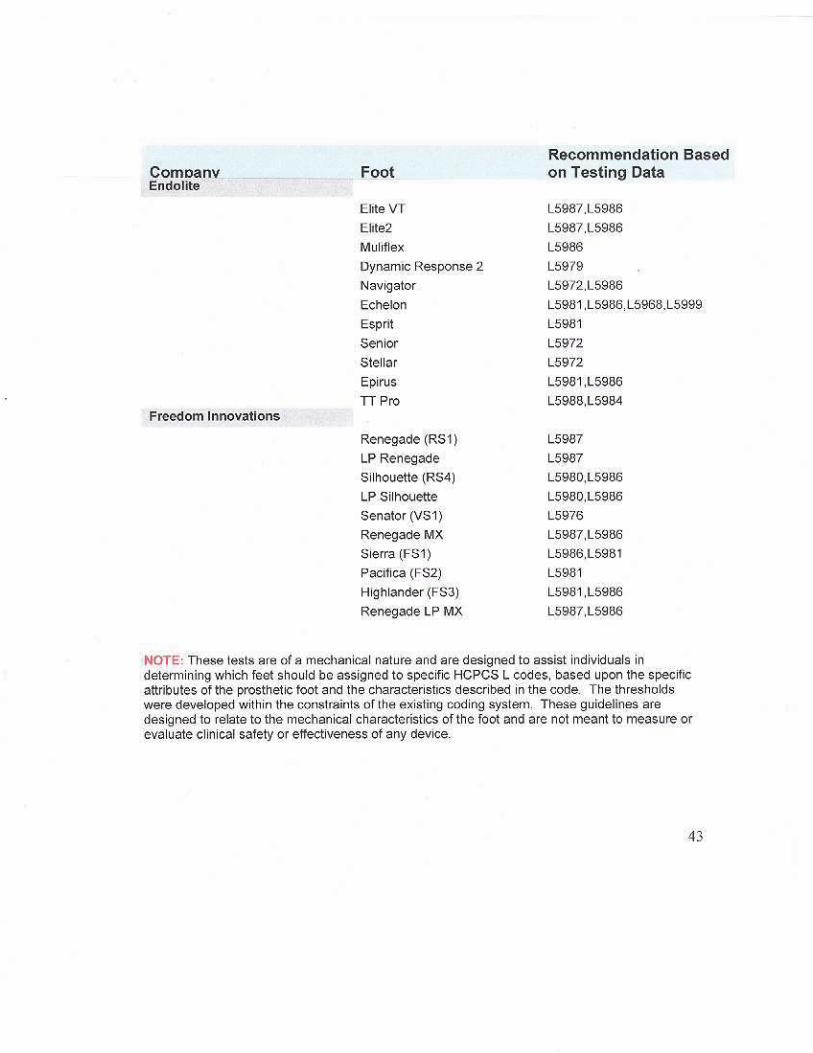
Appendix B: Test Criteria and Corresponding HCPCS codes Appendix C: Prosthetic Feet and Corresponding HCPCS codes
2
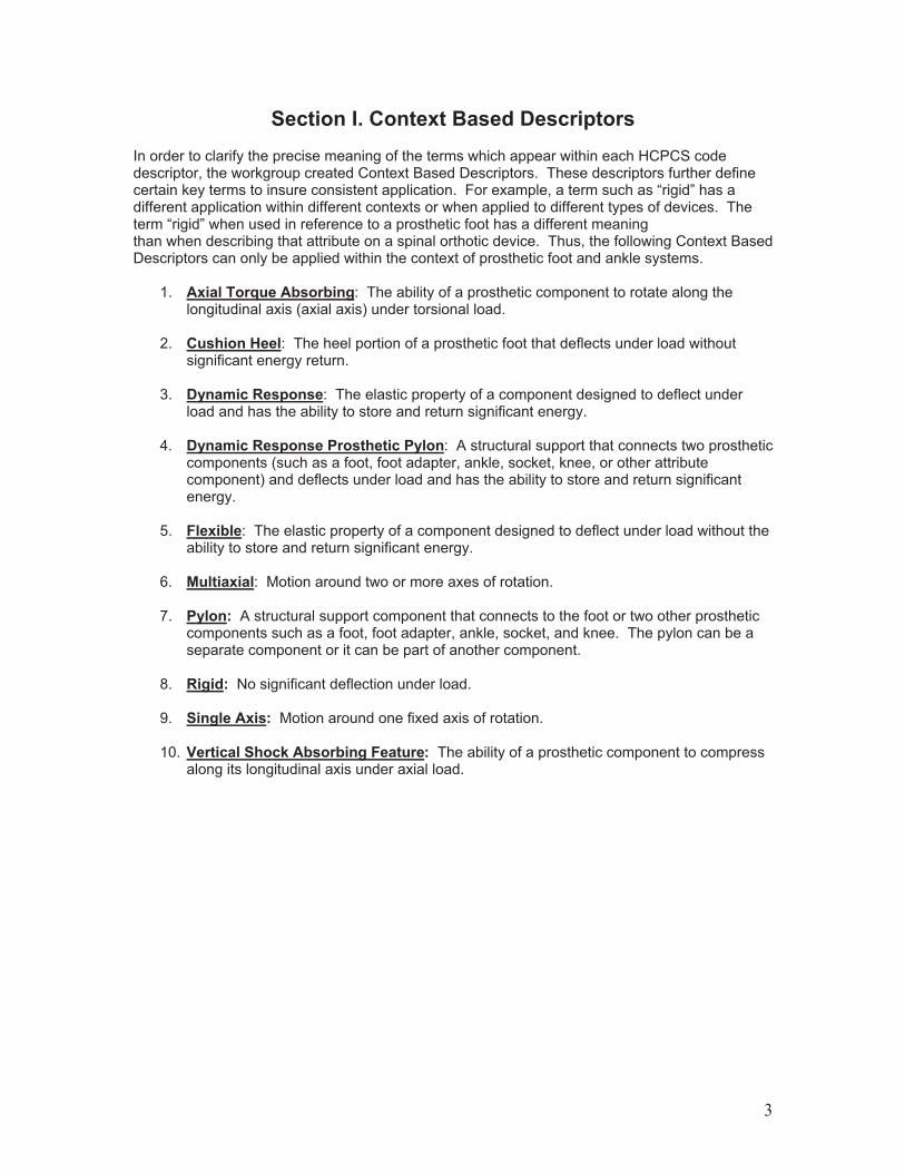
Section I. Context Based DescriptorsIn order to clarify the precise meaning of the terms which appear within each HCPCS code descriptor, the workgroup created Context Based Descriptors. These descriptors further define certain key terms to insure consistent application. For example, a term such as “rigid” has a different application within different contexts or when applied to different types of devices. The term “rigid” when used in reference to a prosthetic foot has a different meaning than when describing that attribute on a spinal orthotic device. Thus, the following Context Based Descriptors can only be applied within the context of prosthetic foot and ankle systems.
1. Axial Torque Absorbing: The ability of a prosthetic component to rotate along the longitudinal axis (axial axis) under torsional load.
2. Cushion Heel: The heel portion of a prosthetic foot that deflects under load without
significant energy return. 3. Dynamic Response: The elastic property of a component designed to deflect under
load and has the ability to store and return significant energy. 4. Dynamic Response Prosthetic Pylon: A structural support that connects two prosthetic
components (such as a foot, foot adapter, ankle, socket, knee, or other attribute component) and deflects under load and has the ability to store and return significant energy.
5. Flexible: The elastic property of a component designed to deflect under load without the
ability to store and return significant energy. 6. Multiaxial: Motion around two or more axes of rotation.
7. Pylon: A structural support component that connects to the foot or two other prosthetic
components such as a foot, foot adapter, ankle, socket, and knee. The pylon can be a separate component or it can be part of another component.
8. Rigid: No significant deflection under load. 9. Single Axis: Motion around one fixed axis of rotation.
10. Vertical Shock Absorbing Feature: The ability of a prosthetic component to compress
along its longitudinal axis under axial load.
3

Section II. Test Descriptions and Methodology These tests are of a mechanical nature and are designed to assist individuals in determining which HCPCS L codes should be recommended for specific, prosthetic feet, based upon the specific attributes of the prosthetic foot and the characteristics described in the code. The thresholds were developed within the constraints of the existing coding system. These guidelines are designed to relate to the mechanical characteristics of the foot and are not meant to measure clinical effectiveness of any device.
All tests are to be conducted using a standard 27 L foot for an A 80 patient. All tests should be performed with common practice methods and at normal conditions such as temperature, humidity, etc.
Keel Test
Test Procedure: Dynamic Keel Test
Scope: This test procedure defines test setup and method for evaluating a foot design for keel/toe dynamics. The results of this test define whether the keel is rigid, flexible or dynamic.
Step 1: Foot Alignment Set-Up ! Place foot on a horizontal plate with the
appropriate heel support to match the heel height of the foot.
! Bring the receiver close enough to the foot to allow you to loosely attach the set screws.
! Apply a 50N load to the device and tighten the set screws.
! Remove the load from the device. ! The foot is now aligned for keel, heel and
vertical displacement testing.
Step 2: Run the Test 2x ! An angle plate of 20° is positioned under the
keel. ! Load the keel to 50N to settle the machine. ! Zero the displacement. ! Load the keel to 1230N and return to 50N.
o The loading rate is 200N/s. o There is no hold at the peak load.
! Zero the displacement. ! Load the keel to 1230N and return to 50N.
o The loading rate is 200N/s. o There is no hold at the peak load.
! Record load and displacement of this run using a minimum of 25 points/sec.
Horizontal flat plate
Heel support
20° plate
Set screws
4

Step 3: Evaluate the Data ! Use the data from cycle #2 to:
o Determine the displacement at 1230N o Calculate the % energy returned using the
trapezoidal method to determine the area under the loading & unloading curves.
Step 4: Compare Results to Keel Classification Criteria
Keel Type Displacement @ 1230N % Return Rigid <25mm NA
Flexible !25mm <75% Dynamic !25mm !75%
Load vs. Displacement Curve -1300
-1200
-1100
-1000
-900
-800
-700
-600
-500
-400
-300
-200
-100
0-18-17-16-15-14-13-12-11-10-9-8-7-6-5-4-3-2-10
Displacement (mm)
Forc
e (N
) Loading Curve
Disp. @ 1230N
Unloading Curve
NOTE: These tests are of a mechanical nature and are designed to assist individuals in determining which HCPCS L codes should be recommended for specific, prosthetic feet, based upon the specific attributes of the prosthetic foot and the characteristics described in the code. The thresholds were developed within the constraints of the existing coding system. These guidelines are designed to relate to the mechanical characteristics of the foot and are not meant to measure clinical effectiveness of any device.
5

Heel Test
Test Procedure: Dynamic Heel Test
Scope: This test procedure defines test setup and method for evaluating a foot design for heel dynamics. The results of this test define whether the heel is dynamic or cushioned. This test is only done on foot designs that have qualified as “dynamic keel”.
Step 1: Test Setup ! Place foot on a horizontal plate with the
appropriate heel support to match the heel height of the foot.
! Bring the receiver close enough to the foot to allow you to loosely attach the set screws.
! Apply a 50N load to the device and tighten the set screws.
! Remove the load from the device. ! The foot is now aligned for keel, heel and
vertical displacement testing.
Step 2: Run the Test 2x ! An angle plate of 15° is positioned under the
heel. ! Load the heel to 50N to settle the machine. ! Zero the displacement. ! Load the heel to 1230N and return to 50N.
o The loading rate is 200N/s. o There is no hold at the peak load.
! Zero the displacement. ! Load the heel to 1230N and return to 50N.
o The loading rate is 200N/s. o There is no hold at the peak load. o Record load and displacement of this run
using a minimum of 25 points/sec.
Step 3: Evaluate Data ! Use the data the second run of Step 2 to:
o Determine the displacement at 1230N.o Calculate the % energy returned using the
trapezoidal method to determine the area under the loading & unloading curves.
Set screws
Heel support
Horizontal flat plate
15° plate
Load vs. Displacement Curve -1300
-1200
-1100
-1000
-900
-800
-700
-600
-500
-400
-300
-200
-100
0-18-17-16-15-14-13-12-11-10-9-8-7-6-5-4-3-2-10
Displacement (mm)
Forc
e (N
)
Disp. @ 1230N Loading
Curve
Unloading Curve
6
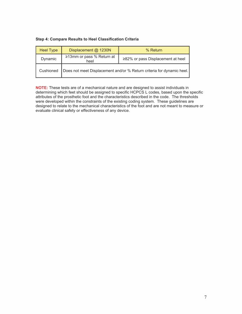
Step 4: Compare Results to Heel Classification Criteria
Heel Type Displacement @ 1230N % Return
Dynamic !13mm or pass % Return at heel !82% or pass Displacement at heel
Cushioned Does not meet Displacement and/or % Return criteria for dynamic heel.
NOTE: These tests are of a mechanical nature and are designed to assist individuals in determining which feet should be assigned to specific HCPCS L codes, based upon the specific attributes of the prosthetic foot and the characteristics described in the code. The thresholds were developed within the constraints of the existing coding system. These guidelines are designed to relate to the mechanical characteristics of the foot and are not meant to measure or evaluate clinical safety or effectiveness of any device.
7
Single Axis Test
Test Procedure: Single Axis Test
Scope: This test procedure defines test setup and method for evaluating a foot design for single axis dynamics. The results of this test define whether or not the foot is single axis.
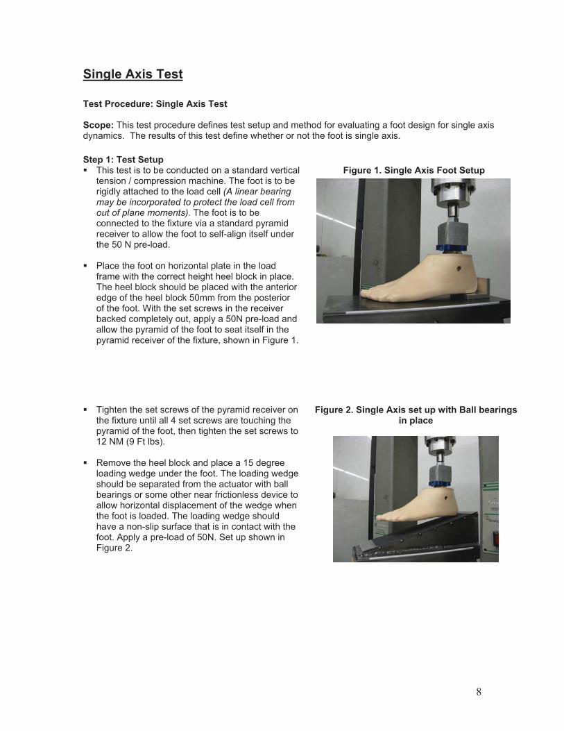
Step 1: Test Setup ! This test is to be conducted on a standard vertical
tension / compression machine. The foot is to be rigidly attached to the load cell (A linear bearing may be incorporated to protect the load cell from out of plane moments). The foot is to be connected to the fixture via a standard pyramid receiver to allow the foot to self-align itself under the 50 N pre-load.
! Place the foot on horizontal plate in the load
frame with the correct height heel block in place. The heel block should be placed with the anterior edge of the heel block 50mm from the posterior of the foot. With the set screws in the receiver backed completely out, apply a 50N pre-load and allow the pyramid of the foot to seat itself in the pyramid receiver of the fixture, shown in Figure 1.
Figure 1. Single Axis Foot Setup
! Tighten the set screws of the pyramid receiver on the fixture until all 4 set screws are touching the pyramid of the foot, then tighten the set screws to 12 NM (9 Ft lbs).
! Remove the heel block and place a 15 degree
loading wedge under the foot. The loading wedge should be separated from the actuator with ball bearings or some other near frictionless device to allow horizontal displacement of the wedge when the foot is loaded. The loading wedge should have a non-slip surface that is in contact with the foot. Apply a pre-load of 50N. Set up shown in Figure 2.
Figure 2. Single Axis set up with Ball bearings in place
8
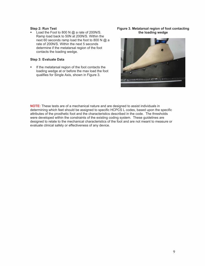
Step 2: Run Test ! Load the Foot to 800 N @ a rate of 200N/S.
Ramp load back to 50N at 200N/S. Within the next 60 seconds ramp load the foot to 800 N @ a rate of 200N/S. Within the next 5 seconds determine if the metatarsal region of the foot contacts the loading wedge.
Step 3: Evaluate Data ! If the metatarsal region of the foot contacts the
loading wedge at or before the max load the foot qualifies for Single Axis, shown in Figure 3.
Figure 3. Metatarsal region of foot contacting the loading wedge
NOTE: These tests are of a mechanical nature and are designed to assist individuals in determining which feet should be assigned to specific HCPCS L codes, based upon the specific attributes of the prosthetic foot and the characteristics described in the code. The thresholds were developed within the constraints of the existing coding system. These guidelines are designed to relate to the mechanical characteristics of the foot and are not meant to measure or evaluate clinical safety or effectiveness of any device.
9
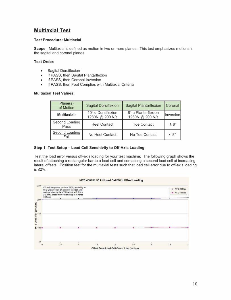
Multiaxial Test Test Procedure: Multiaxial Scope: Multiaxial is defined as motion in two or more planes. This test emphasizes motions in the sagital and coronal planes. Test Order:
! Sagital Dorsiflexion ! If PASS, then Sagital Plantarflexion ! If PASS, then Coronal Inversion ! If PASS, then Foot Complies with Multiaxial Criteria
Multiaxial Test Values:
Plane(s) of Motion Sagital Dorsiflexion Sagital Plantarflexion Coronal
Multiaxial: 10° " Dorsiflexion 1230N @ 200 N/s
8° " Plantarflexion 1230N @ 200 N/s Inversion
Second Loading Pass Heel Contact Toe Contact ! 8°
Second Loading Fail No Heel Contact No Toe Contact < 8°
Step 1: Test Setup – Load Cell Sensitivity to Off-Axis Loading Test the load error versus off-axis loading for your test machine. The following graph shows the result of attaching a rectangular bar to a load cell and contacting a second load cell at increasing lateral offsets. Position feet for the multiaxial tests such that load cell error due to off-axis loading is #2%.
10

Dorsiflexion:
The dorsiflexion test illustrated graphically:
Load the roller plates, bearing plate onto the force-deflection test machine:
The roller plate shown in the above is made of four Ball Bearing Miniature Transfer Plates TIG welded together for easier handling. They are 12” X 2.5” X 3/8” and available from mcmaster.com part number 5764K32. Whether welded together or not, they should fully support fixtures.
11

Load the fixture, which can be a sine plate as shown here, or a block of material with a 10-degree slope:
Before mounting the foot, set up the sine plate for dorsiflexion test angle of 10 degrees, and then drop the plate back to 0 degrees for zeroing the foot:
12

Load the foot and bring the pyramid and pyramid receiver together gently to contact:
Load to 50N and hand tighten the setscrews such that all four setscrews contact the pyramid facets:
13

Tighten the set screws with a torque wrench alternately in at least 2 stages up to the final value of 11N-m.
Raise the foot and add anti-slip grip tape under the heel plate and foot to prevent sliding during loading (or simply affix it permanently to your sine plate or block). Make sure the heel plate also sits on the grip tape so the heel height remains correct. Lower the foot to contact and 50N settling load. The following shows the foot ready for testing at a 50N load:
14
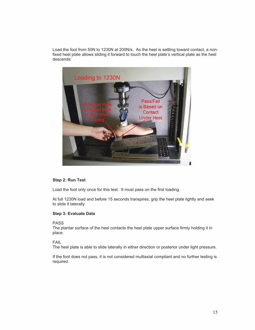
Load the foot from 50N to 1230N at 200N/s. As the heel is settling toward contact, a non-fixed heel plate allows sliding it forward to touch the heel plate’s vertical plate as the heel descends:
Step 2: Run Test Load the foot only once for this test. It must pass on the first loading. At full 1230N load and before 15 seconds transpires, grip the heel plate lightly and seek to slide it laterally. Step 3: Evaluate Data
PASS The plantar surface of the heel contacts the heel plate upper surface firmly holding it in place. FAIL The heel plate is able to slide laterally in either direction or posterior under light pressure. If the foot does not pass, it is not considered multiaxial compliant and no further testing is required.
15
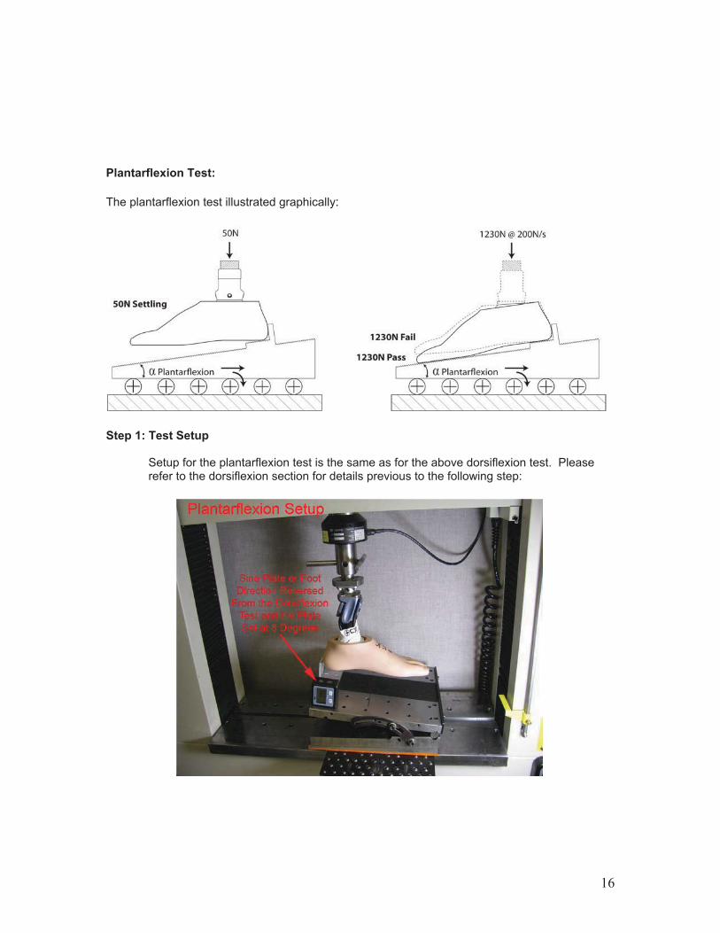
Plantarflexion Test:
The plantarflexion test illustrated graphically:
Step 1: Test Setup
Setup for the plantarflexion test is the same as for the above dorsiflexion test. Please refer to the dorsiflexion section for details previous to the following step:
16

Loaded as shown below to the settling load of 50N, the heel plate must be against the back of the foot. Place a sheet of standard (20 pound) printing paper under the overhanging toe as shown. The foot is ready for loading to 1230N at 200N/s:
Step 2: Run Test Within 15 seconds of reaching 1230N, check to see if the paper under the toe can be slid out.
Step 3: Evaluate Data
PASS The plantar surface of the toe contacts the paper such that it cannot be slid out. FAIL The plantar surface of the toe does not contact enough to keep the paper from sliding out. If the foot does not pass, it is not considered multiaxial compliant and no further testing is required.
17
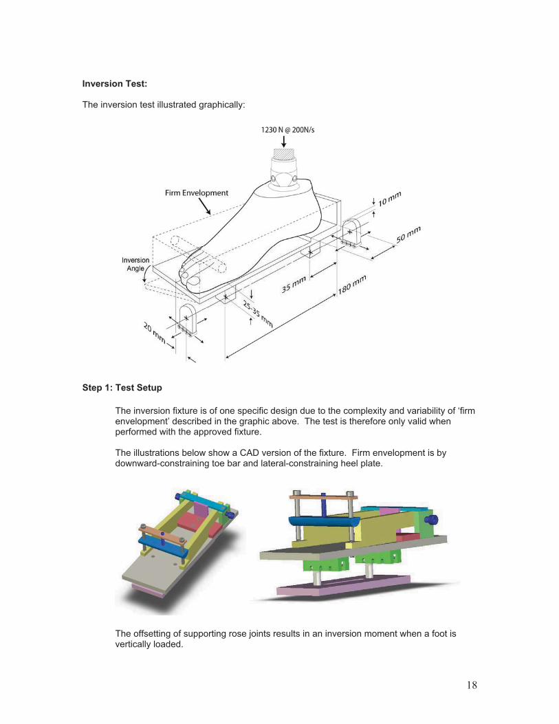
Inversion Test:
The inversion test illustrated graphically:
Step 1: Test Setup
The inversion fixture is of one specific design due to the complexity and variability of ‘firm envelopment’ described in the graphic above. The test is therefore only valid when performed with the approved fixture. The illustrations below show a CAD version of the fixture. Firm envelopment is by downward-constraining toe bar and lateral-constraining heel plate.
The offsetting of supporting rose joints results in an inversion moment when a foot is vertically loaded.
18

Setup is similar to the previous two tests. The same roller plate and fixture-bearing plates are used, but the foot should be reoriented 90 degrees for better visibility on loading.
Test machine setup:
Feet are loaded into the fixture off line:
19
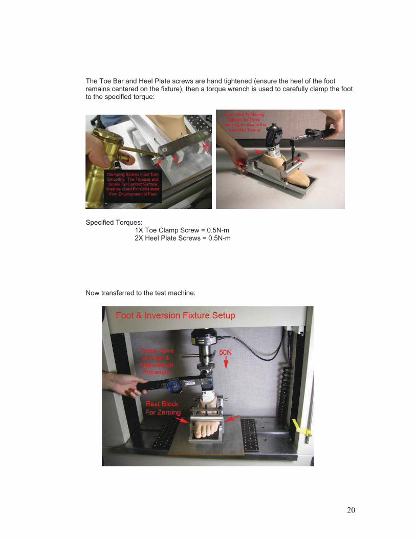
The Toe Bar and Heel Plate screws are hand tightened (ensure the heel of the foot remains centered on the fixture), then a torque wrench is used to carefully clamp the foot to the specified torque:
Specified Torques: 1X Toe Clamp Screw = 0.5N-m
2X Heel Plate Screws = 0.5N-m
Now transferred to the test machine:
20
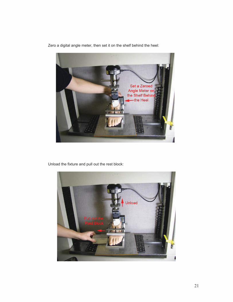
Zero a digital angle meter, then set it on the shelf behind the heel:
Unload the fixture and pull out the rest block:
21

Step 2: Run Test
The inversion test requires the foot to be loaded twice. Order of loading and recording: Setup:
! 0N to hand tighten the pyramid receiver setscrews. ! 50N to zero the foot. ! Unload to pull out the rest block.
Testing:
! Load to 50N and dwell a few seconds. ! Load to 1230N @ 200N/s and dwell for ~15 seconds. ! Unload to 50N and dwell no more than 15 seconds reading and recording the
settling angle, "settling. ! Load the second time to 1230N @ 200N/s and dwell for ~15 seconds reading
and recording the measure inversion angle, "1230N .
Running the test, read the settling angle on the second loading:
Record the settling angle, "settling = ________
22
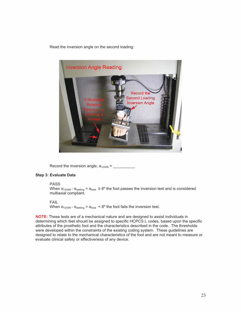
Read the inversion angle on the second loading:
Record the inversion angle, "1230N = __________
Step 3: Evaluate Data PASS When "1230N - "settling = "total ! 8º the foot passes the inversion test and is considered multiaxial compliant.
FAIL When "1230N - "settling = "total < 8º the foot fails the inversion test.
NOTE: These tests are of a mechanical nature and are designed to assist individuals in determining which feet should be assigned to specific HCPCS L codes, based upon the specific attributes of the prosthetic foot and the characteristics described in the code. The thresholds were developed within the constraints of the existing coding system. These guidelines are designed to relate to the mechanical characteristics of the foot and are not meant to measure or evaluate clinical safety or effectiveness of any device.
23
Axial Torque Absorption Test Test Procedure: Axial Torque Absorbing Feature
Scope: Axial torque absorption is the ability of a prosthetic component to rotate along its longitudinal axis under torsional load. This test procedure defines test setup and method for evaluating a foot and/or adapter designed for axial torque absorption.
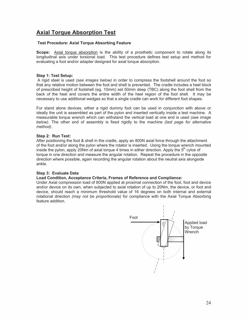
Step 1: Test Setup: A rigid steel is used (see images below) in order to compress the footshell around the foot so that any relative motion between the foot and shell is prevented. The cradle includes a heel block of prescribed height of footshell (eg. 10mm) set 50mm deep (TBC) along the foot shell from the back of the heel and covers the entire width of the heel region of the foot shell. It may be necessary to use additional wedges so that a single cradle can work for different foot shapes. For stand alone devices, either a rigid dummy foot can be used in conjunction with above or ideally the unit is assembled as part of the pylon and inserted vertically inside a test machine. A measurable torque wrench which can withstand the vertical load at one end is used (see image below). The other end of assembly is fixed rigidly to the machine (last page for alternative method).
Step 2: Run Test:After positioning the foot & shell in the cradle, apply an 800N axial force through the attachment of the foot and/or along the pylon where the rotator is inserted. Using the torque wrench mounted inside the pylon, apply 20Nm of axial torque 4 times in either direction. Apply the 5th cylce of torque in one direction and measure the angular rotation. Repeat the procedure in the opposite direction where possible, again recording the angular rotation about the neutral axis alongside ankle.
Step 3: Evaluate Data Load Condition, Acceptance Criteria, Frames of Reference and Compliance: Under Axial compression load of 800N applied at proximal connection of the foot, foot and device and/or device on its own, when subjected to axial rotation of up to 20Nm, the device, or foot and device, should reach a minimum threshold value of 16 degrees on both internal and external rotational direction (may not be proportionate) for compliance with the Axial Torque Absorbing feature addition. Foot
Applied load by Torque Wrench
24

Methods of Loading:
Directly apply a torque wrench capable of withstanding and transferring 800N axial compression through means of connection with a thrust washer. Apply up to 20 Nm of axial rotation and measure the axial rotation angle. The rotational angle can be measured electronically or mechanically
Add the angular rotation values from both directions to get the angular range
Key Conditions:
a) Special cradle made of rigid steel needs to contain the foot shell and be able to pre-compress the soft foam of the foot shell either by means of moving wedges or standard slip gauges that under application of compressive axial force pre-compresess the soft foam shell.
b) The heel height block of matching height to the foot, 50mm deep covering full width of the heel made of aluminium or material with similar rigidity must be applied to the cradle.
c) The compression in the foot shell must be of sufficient level to stop any relative motion of the internal keel/heel to the footshell, especially if loose interchangable foot shell is used.
Overall Angular Range
Qualifies for Axial Torque Absorption
!16° yes <16° no
d) Application of means of rotation must be about the pylon axis or longitudinal axis of the device or perpendicular to proximal horizontal face of the foot at ankle level about ankle.
e) This rotational measurement is about the center of the ankle about the longitudinal axis of the pylon or an axis perpendicular to the proximal horizontal plane face of the foot, is about ankle center and referenced to mid line of the foot, which is marked by a line crossing two points, one at half distance of the width of the sole at ankle center or point of attachment and the other at ball of the foot region at 120mm anterior to ankle at half distant width line perpendicular (direction of progression) or top of the lateral border of the foot.
25

f) Standard 27 L category 4 foot and (A 80) torque absorbing devices should be used.
g) Apply a pre-load of 50 N prior to securing all connection and pressure plates compression.
h) Ensure the proximal connection is rigidly fixed to axial compression actuator prior to loading.
i) Apply the 800 N load through a thrust washer to 20 Nm of axial torque applied and return to pre-load 5 consecutive times and on the 5th application, measure the rotational angle. Repeat measurements internally and externally twice and note variation for return to zero reference starting point. Record the mean value of axial rtotational angle in degrees.
j) Accuracy of applied load is +/- 10N or +/- 1 Nm with calibration certificates and competency.
k) Accuracy of measurements of angle is +/- 0.5 degrees with laboratory competency.
Alternative Method of Applying Torque:
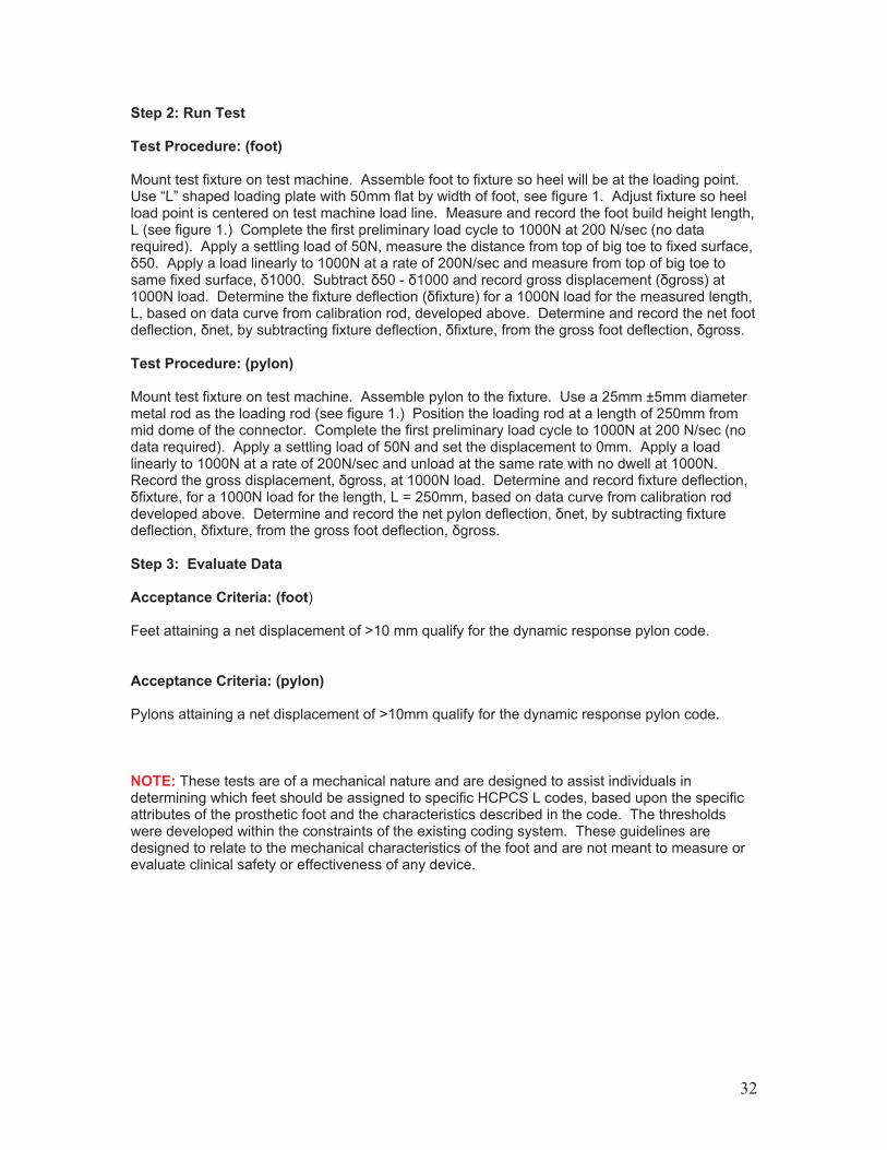
Apply a force 100N to the anterior portion of the foot (see image below) at the height of 20mm from the base of the foot and 200mm from the ankle joint perpendicular to the base of the foot as shown below. The force can be servo driven or manually by hand.
26

Key Conditions:
a) Special cradle made of rigid steel needs to contain the foot shell as per previous method.
b) All key points of previous method apply to this alternative method.
c) Acceptance criteria and compliance is the same as previous method.
Alternative Frames of Reference for Method of Loading (see illustration below):
Spring balance/load cell
NOTE: These tests are of a mechanical nature and are designed to assist individuals in determining which feet should be assigned to specific HCPCS L codes, based upon the specific attributes of the prosthetic foot and the characteristics described in the code. The thresholds were developed within the constraints of the existing coding system. These guidelines are designed to relate to the mechanical characteristics of the foot and are not meant to measure or evaluate clinical safety or effectiveness of any device.
Load
Frictionless pulley
Applied load
Foot
27
Vertical Loading TestTest Procedure: Vertical Loading Feature Scope: This feature is the ability of a prosthetic component to compress along its longitudinal axis under axial load.
This protocol describes: a) A test setup to evaluate vertical loading properties of a prosthetic foot. b) A test setup to evaluate vertical loading properties of an endoskeletal component. c) Data analysis methods specific to these setups.
Equipment & Conditions: ! A rigid, certified test rig with an actuator capable of 1230N force or more. ! A flat, sliding load plane with rigid surface; solid metal or plastic which will not deflect
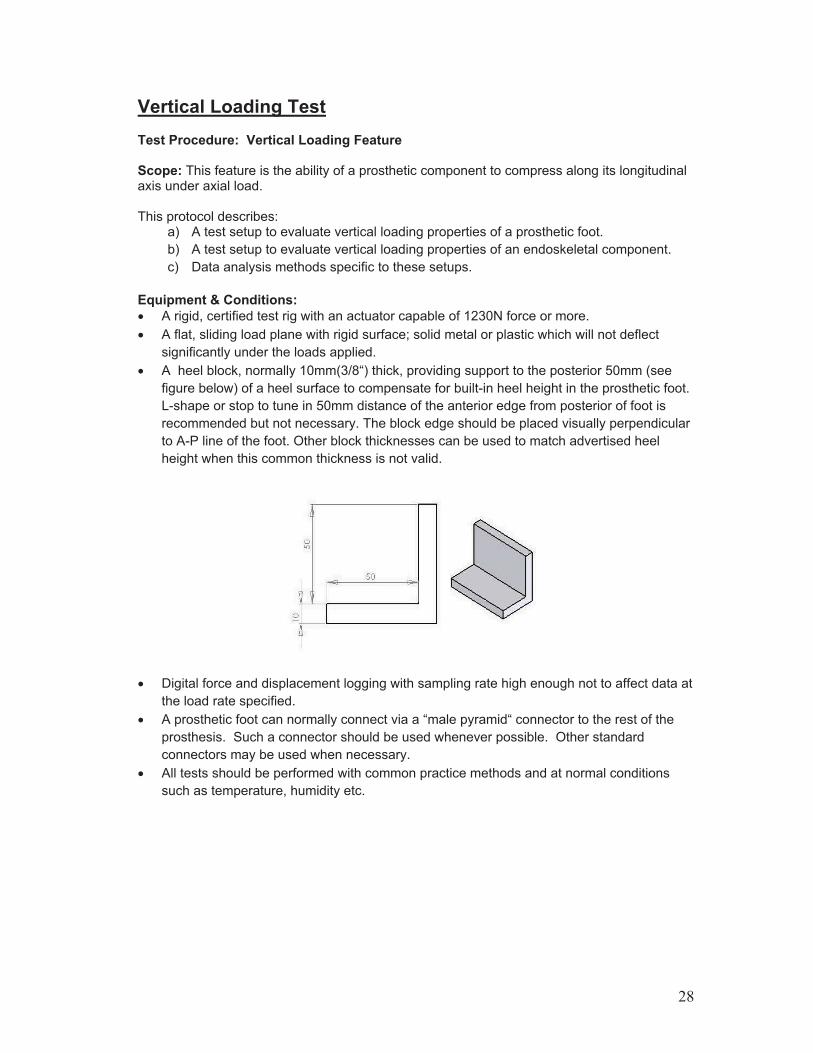
significantly under the loads applied. ! A heel block, normally 10mm(3/8“) thick, providing support to the posterior 50mm (see
figure below) of a heel surface to compensate for built-in heel height in the prosthetic foot. L-shape or stop to tune in 50mm distance of the anterior edge from posterior of foot is recommended but not necessary. The block edge should be placed visually perpendicular to A-P line of the foot. Other block thicknesses can be used to match advertised heel height when this common thickness is not valid.
! Digital force and displacement logging with sampling rate high enough not to affect data at the load rate specified.
! A prosthetic foot can normally connect via a “male pyramid“ connector to the rest of the prosthesis. Such a connector should be used whenever possible. Other standard connectors may be used when necessary.
! All tests should be performed with common practice methods and at normal conditions such as temperature, humidity etc.
28
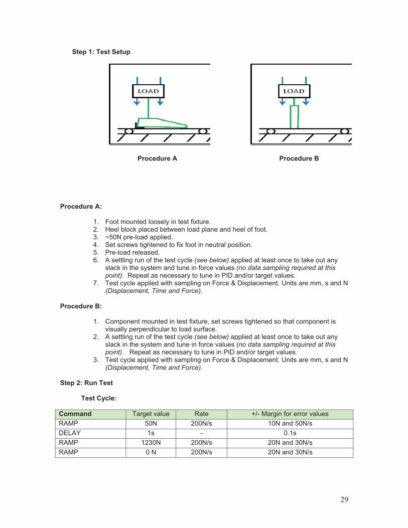
Step 1: Test Setup
Procedure A Procedure B
Procedure A:
1. Foot mounted loosely in test fixture. 2. Heel block placed between load plane and heel of foot. 3. ~50N pre-load applied. 4. Set screws tightened to fix foot in neutral position. 5. Pre-load released. 6. A settling run of the test cycle (see below) applied at least once to take out any
slack in the system and tune in force values (no data sampling required at this point). Repeat as necessary to tune in PID and/or target values.
7. Test cycle applied with sampling on Force & Displacement. Units are mm, s and N(Displacement, Time and Force).
Procedure B:
1. Component mounted in test fixture, set screws tightened so that component is visually perpendicular to load surface.
2. A settling run of the test cycle (see below) applied at least once to take out any slack in the system and tune in force values (no data sampling required at this point). Repeat as necessary to tune in PID and/or target values.
3. Test cycle applied with sampling on Force & Displacement. Units are mm, s and N(Displacement, Time and Force).
Step 2: Run Test
Test Cycle:
Command Target value Rate +/- Margin for error values RAMP 50N 200N/s 10N and 50N/s DELAY 1s - 0.1s RAMP 1230N 200N/s 20N and 30N/s RAMP 0 N 200N/s 20N and 30N/s
29

Step 3: Evaluate Data
The 50N settling value is intended to define as clear a “starting“ position as possible. However, it is unlikely to match 50N exactly, and therefore, when an average of three datapoints in a row is >=50N, the middle point is set as DataPoint#1. The datapoint with the highest displacement value is selected as DataPoint#2. Vertical Displacement = DataPoint#2 – DataPoint#1
Results Vertical Displacement < 10mm
Does not meet vertical loading test a) Prosthetic foot
Vertical Displacement >= 10mm
Does meet vertical loading test
Vertical Displacement < 6mm
Does not meet vertical loading test b) Endoskeletal component Vertical Displacement
>= 6mm Does meet vertical loading test
NOTE: These tests are of a mechanical nature and are designed to assist individuals in determining which feet should be assigned to specific HCPCS L codes, based upon the specific attributes of the prosthetic foot and the characteristics described in the code. The thresholds were developed within the constraints of the existing coding system. These guidelines are designed to relate to the mechanical characteristics of the foot and are not meant to measure or evaluate clinical safety or effectiveness of any device.
30

Dynamic Pylon TestTest Procedure: Dynamic Pylon Scope: This test procedure defines the test setup and method for all pylons without foot assembly and foot assemblies, which have qualified as dynamic keel and dynamic heel. The maximum length from fixture to load point that can be used for these tests is 250mm. Step 1: Test Setup Test fixture to hold pylons and feet must have adequate stiffness and the deflection for the fixture as a function for loading position also must be determined. Assemble a steel 30 mm rod into the test fixture (see figure 1.) The rod must be of sufficient length to be point loaded at several positions out to a maximum distance of 250mm as measured from the mid dome to load point. Test the rod at each position per the test procedure below (1000N). The deflection at 250mm must be less than 8.0 mm to qualify as a rigid fixture. Also, plot the fixture deflection ($fixture) as a function of loading position length, L and generate a curve through these points. This will be used to determine net deflection. For testing the product, remove the 30mm rod and connect the foot or pylon directly to the fixture. The basic test set up is shown in figure 1.
Figure 1. Test setup for dynamic response pylon
31
Step 2: Run Test
Test Procedure: (foot)
Mount test fixture on test machine. Assemble foot to fixture so heel will be at the loading point. Use “L” shaped loading plate with 50mm flat by width of foot, see figure 1. Adjust fixture so heel load point is centered on test machine load line. Measure and record the foot build height length, L (see figure 1.) Complete the first preliminary load cycle to 1000N at 200 N/sec (no data required). Apply a settling load of 50N, measure the distance from top of big toe to fixed surface, $50. Apply a load linearly to 1000N at a rate of 200N/sec and measure from top of big toe to same fixed surface, $1000. Subtract $50 - $1000 and record gross displacement ($gross) at 1000N load. Determine the fixture deflection ($fixture) for a 1000N load for the measured length, L, based on data curve from calibration rod, developed above. Determine and record the net foot deflection, $net, by subtracting fixture deflection, $fixture, from the gross foot deflection, $gross. Test Procedure: (pylon)
Mount test fixture on test machine. Assemble pylon to the fixture. Use a 25mm ±5mm diameter metal rod as the loading rod (see figure 1.) Position the loading rod at a length of 250mm from mid dome of the connector. Complete the first preliminary load cycle to 1000N at 200 N/sec (no data required). Apply a settling load of 50N and set the displacement to 0mm. Apply a load linearly to 1000N at a rate of 200N/sec and unload at the same rate with no dwell at 1000N. Record the gross displacement, $gross, at 1000N load. Determine and record fixture deflection, $fixture, for a 1000N load for the length, L = 250mm, based on data curve from calibration rod developed above. Determine and record the net pylon deflection, $net, by subtracting fixture deflection, $fixture, from the gross foot deflection, $gross.
Step 3: Evaluate Data
Acceptance Criteria: (foot) Feet attaining a net displacement of >10 mm qualify for the dynamic response pylon code. Acceptance Criteria: (pylon)
Pylons attaining a net displacement of >10mm qualify for the dynamic response pylon code.
NOTE: These tests are of a mechanical nature and are designed to assist individuals in determining which feet should be assigned to specific HCPCS L codes, based upon the specific attributes of the prosthetic foot and the characteristics described in the code. The thresholds were developed within the constraints of the existing coding system. These guidelines are designed to relate to the mechanical characteristics of the foot and are not meant to measure or evaluate clinical safety or effectiveness of any device.
32
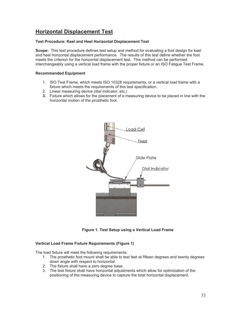
Horizontal Displacement TestTest Procedure: Keel and Heel Horizontal Displacement Test Scope: This test procedure defines test setup and method for evaluating a foot design for keel and heel horizontal displacement performance. The results of this test define whether the foot meets the criterion for the horizontal displacement test. This method can be performed interchangeably using a vertical load frame with the proper fixture or an ISO Fatigue Test Frame. Recommended Equipment
1. ISO Test Frame, which meets ISO 10328 requirements, or a vertical load frame with a fixture which meets the requirements of this test specification.
2. Linear measuring device (dial indicator, etc.) 3. Fixture which allows for the placement of a measuring device to be placed in line with the
horizontal motion of the prosthetic foot.
Figure 1. Test Setup using a Vertical Load Frame
Vertical Load Frame Fixture Requirements (Figure 1)
The load fixture will meet the following requirements: 1. The prosthetic foot mount shall be able to test feet at fifteen degrees and twenty degrees
down angle with respect to horizontal. 2. The fixture shall have a zero degree base. 3. The test fixture shall have horizontal adjustments which allow for optimization of the
positioning of the measuring device to capture the total horizontal displacement.
33

4. The fixture will have a slide which allows the foot to slide horizontally forward or backward. This slide will have minimal friction.
5. The fixture shall have a construction which minimizes deflection in the fixture. 6. See Figure 1.
ISO Frame Fixture Requirements (Figure 2)
The fixture for the measurement of the horizontal displacement shall meet the following requirements:
1. The fixture shall rigidly mount on the existing frame. 2. The fixture will allow adjustment in the line of motion of the foot. 3. The fixture will provide mounting for a linear measurement device (dial indicator, etc).
Step 1: Test Setup
Vertical Test Frame (Figure 1)
1. Select the appropriate upper mount angle for loading the keel or heel. a. To test the heel, a 15° angle mount is used to mount the prosthetic foot. b. To test the keel toe, a 20° angle mount is used to mount the prosthetic foot.
2. Place the upper portion of the fixture in the upper jaws of the test frame. Using the appropriate adapter, connect the proximal connection point of the foot to be tested to the upper portion of the fixture. The upper fixture must be of a rigid construction. Any measurable flexibility of the upper fixture will influence test results.
3. Place the test fixture in the test frame. Securely attach the foot test fixture to the hydraulic ram (i.e. Clamp the lower jaws of the test frame to the fixture, verifying a horizontal alignment, and ensuring the fixture is properly supported by the jaws).
4. Verify that the primary axis of the foot is in line with the slide mount on the lower portion of the fixture.
ISO Test Frame (Figure 2)
1. Mount the prosthetic foot in the test frame. Orient the primary axis of the foot in the direction of horizontal motion.
2. Mount the measuring device on the front of the toe or heel plate. Position the device to capture the full range of motion. If the range of motion is greater than the capacity of the device, pause the test, note the current deflection measured. Reposition the device to capture the rest of the motion. Add the two deflections and this is the total deflection.
Step 2: Run Test
Heel Test 1. If using the ISO Test Frame locate the measuring device to the heel actuator. If using the
Vertical Test Frame, mount the prosthetic foot to the 15° angle mount. 2. Pre-load the prosthetic foot to 50 N. 3. Apply a “dry run” of the actuator, applying a 1230 N (+/- 10 N) compressive load,
observing which direction the linear slide plate will move, and then set the vertical load again to 50 N. Zero or note the horizontal and vertical positions, not the load.
4. Load the prosthetic foot to 1230 N (+/- 10 N). Note the horizontal and vertical positions, as well as the load.
Toe Keel Test 1. If using the ISO Test Frame. locate the measuring device to the toe actuator. If using the
Vertical Test Frame mount the prosthetic foot to the 20° angle mount. Hang the toe about an inch over the edge of the slide block if the toes of the prosthesis are soft or spongy.
34
2. Pre-load the prosthetic foot to 50 N. Zero or note the horizontal and vertical positions, note the load.
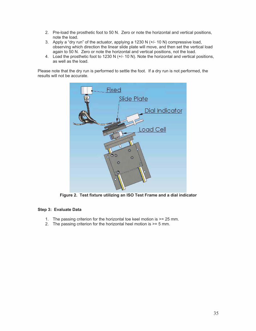
3. Apply a “dry run” of the actuator, applying a 1230 N (+/- 10 N) compressive load, observing which direction the linear slide plate will move, and then set the vertical load again to 50 N. Zero or note the horizontal and vertical positions, not the load.
4. Load the prosthetic foot to 1230 N (+/- 10 N). Note the horizontal and vertical positions, as well as the load.
Please note that the dry run is performed to settle the foot. If a dry run is not performed, the results will not be accurate.
Figure 2. Test fixture utilizing an ISO Test Frame and a dial indicator
Step 3: Evaluate Data
1. The passing criterion for the horizontal toe keel motion is >= 25 mm. 2. The passing criterion for the horizontal heel motion is >= 5 mm.
35

Section III. Summary By using the context based descriptors, testing descriptions and methodology outlined in Sections I and II, appropriate HCPCS codes can be recommended for prosthetic feet. Once the Workgroup had completed its classification of existing prosthetic feet, each participating manufacturer reviewed the report and this classification. To acknowledge their participation, each manufacturer was asked to read and sign the following statement:
Manufacturers’ Acknowledgement/Acceptance of the Publication of the Final Manuscript from the AOPA Prosthetic Foot Manufacturers Project Your company has been an active participant and contributor to the AOPA Prosthetic Foot Manufacturers Project. This project is now drawing to its completion. We have a final manuscript, a copy of which is attached, and we plan to present the document and a narrative on its findings to the PDAC and CMS within the next month. Congratulations to you and others from your company who worked on and contributed to this very important publication. We are now formally approaching each of the participating/contributing companies, and formally asking their acknowledgement/approval for the final text of the publication. All companies have had an equal opportunity to participate, provide data and present viewpoints. It is now time for each company to have the opportunity to indicate whether they acknowledge and accept the end product. We trust that you will want to do so, so that your company’s name can be listed as one of the participating companies in presentations/publications of this document. This is essentially a “Yes/No” action—consideration of all specific text and issues is complete—this is the final document for your up or down vote. What Your Acknowledgement/Approval Means By signing below and returning this Acknowledgement/Approval to AOPA you are stating the following three assertions and nothing more. You are not stating that you agree with or are making a permanent commitment to any or all findings.
1. Our company participated in meetings and contributed our input and talents to the development of this document.
2. Our company has had the opportunity to review the final text of the resulting publication document.
3. Our company agrees to having our name included on the list of companies that developed this document.
Signature: ____________________________________________________ Our company _____________________________________________(insert name) does/does not (circle appropriate text) acknowledge and approve the final publication document of the AOPA Prosthetic Foot Manufacturers Project, and authorizes inclusion of our company’s name among the list of participants and contributors to the development of this publication. Date:_____________________________
36

In addition, the manufacturers were offered the option of having their feet tested by an independent testing laboratory of their choosing.
Manufacturer’s Option for Independent Testing Testing throughout this project was conducted on various products/devices submitted by manufacturers, using the test methods outlined in the attached final draft using a round robin testing mechanism whereby the feet to be tested were circulated to multiple manufacturers, each of which performed the applicable test on those feet. This mechanism helped establish the reproducibility of the test results. The composite results from the round robin testing were presented in the tables that appear on pgs. 39-40. The process does afford the opportunity for a manufacturer, should they wish, to pursue, at their expense, independent product testing. We believe the results of the round robin testing to be accurate and legitimate, and to the extent that manufacturers say they were completely satisfied with the results of round robin testing performed by other manufacturers, are requested to execute a waiver of liability as to both AOPA and all other companies involved in the project. For any manufacturer who does wish to secure independent testing, at its own expense, here is the process that has been established. Such company shall advise AOPA that it wishes to pursue independent testing. AOPA will notify the company of the independent testing facility which AOPA has identified as well as applicable fees charged by that facility. The manufacturer can then engage the laboratory for its services and supply the feet to be tested, with the same standard testing methods to be used. The independent testing facility shall timely provide the results to both AOPA and the manufacturer, together with its attestation that the methods prescribed by AOPA have been strictly followed. There is a second and final option afforded to a company which engages, at its own expense, the independent testing facility that AOPA has identified, where the manufacturer disagrees with the results of the independent testing conducted by the AOPA contractor. Such a manufacturer could take one final step, of securing testing of its product(s) engaging two additional independent testing labs of the company’s choosing, again with all costs borne by the manufacturer, which attest that they will test the product using the identical testing methods specified in this document, with each independent testing facility providing a report on the results of their testing to both AOPA and the manufacturer immediately upon completion of the testing. If both of those results agree with each other, but disagree with the results from the AOPA contractor, then the results from the two additional tests would be honored and substituted for the AOPA contractor results in the final AOPA report. Manufacturer waiver of option to conduct independent testing: As an authorized representative of _________________________ company, I do hereby affirm that our company is completely satisfied with the results of round robin testing performed on our company’s products by other manufacturers, and do further hereby affirmatively execute this waiver of liability as to both AOPA and all other companies involved in the project, holding all of them harmless from any claim of damage originating from our company. Signed: ____________________________________________________
For________________________________________________________(Company) Date _______________________________
37
Participants We would like to thank the following manufacturers who participated in this Project:
! American Prosthetic Components, Inc. ! BioQuest Prosthetics ! College Park Industries, Inc. ! Endolite/Blatchford, Inc. ! Freedom Innovations, LLC. ! Kingsley Manufacturing! Ohio Willow Wood, Inc. ! Ossur ! Otto Bock HealthCare LLP ! Trulife, Inc.
Without their support and input, this project could not have been completed. Disclaimer: Information contained in this publication is the consensus opinion of the AOPA Prosthetic Foot Manufacturers Task Force based on information known and available as of the date when the matter was last reviewed. This publication does not represent any official policy or position of the American Orthotic & Prosthetic Association, nor of its individual members, and should not be presented or quoted as such. The American Orthotic & Prosthetic Association does not assume, and cannot accept any responsibility for any damages or injury which may result from reliance upon this voluntary educational publication. This publication is a holistic document, and AOPA cautions particularly against quoting this publication in part, or excerpting specific portions of this document, and any such usage is not authorized. Copyright, 2010, American Orthotic & Prosthetic Association. All rights reserved.
38

Appendix A
Summary of Test Thresholds
Test Threshold
1. Keel Test Keel Type Displacement @ 1230N % Return Rigid <25mm NA
Flexible !25mm <75% Dynamic !25mm !75%
2. Heel Test Heel Type Displacement @ 1230N % Return
Dynamic !13mm or pass % Return at heel !82% or pass Displacement at heel
Cushioned Does not meet Displacement and/or % Return criteria for dynamic heel.
3. Single Axis Test
If the metatarsal region of the foot contacts the loading wedge at or before the max load the foot qualifies for Single Axis
Plane(s) of Motion Sagital Dorsiflexion Sagital Plantarflexion Coronal
Multiaxial: 10° " Dorsiflexion 1230N @ 200 N/s
8° " Plantarflexion 1230N @ 200 N/s Inversion
Second Loading Pass Heel Contact Toe Contact ! 8°
4. Multiaxial Test
Second Loading Fail No Heel Contact No Toe Contact < 8° ! Sagital Dorsiflexion tested first
! If PASS, then Sagital Plantarflexion ! If PASS, then Coronal Inversion ! If PASS, then Foot Complies with Multiaxial Criteria
5. Axial TorqueAbsorption Test
Under Axial compression load of 800N applied at proximal connection of the foot, foot and device and/or device on its own, when subjected to axial rotation of up to 20Nm, the device, or foot and device, should reach a minimum threshold value of 16 degrees on both internal and external rotational direction (may not be proportionate) for compliance with the Axial Torque Absorbing feature addition.
NOTE: These tests are of a mechanical nature and are designed to assist individuals in determining which feet should be assigned to specific HCPCS L codes, based upon the specific attributes of the prosthetic foot and the characteristics described in the code. The thresholds were developed within the constraints of the existing coding system. These guidelines are designed to relate to the mechanical characteristics of the foot and are not meant to measure or evaluate clinical safety or effectiveness of any device.
39
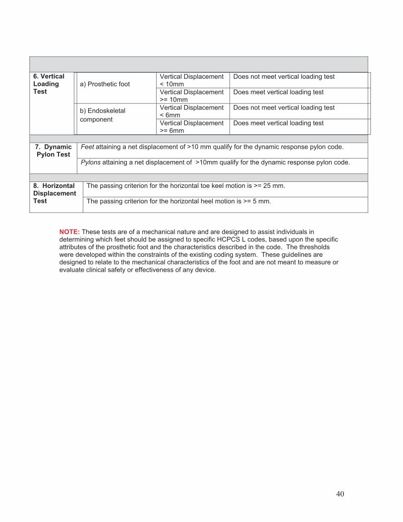
6. Vertical LoadingTest
Vertical Displacement < 10mm
Does not meet vertical loading test a) Prosthetic foot
Vertical Displacement >= 10mm
Does meet vertical loading test
Vertical Displacement < 6mm
Does not meet vertical loading test b) Endoskeletal component Vertical Displacement
>= 6mm Does meet vertical loading test
Feet attaining a net displacement of >10 mm qualify for the dynamic response pylon code.
7. Dynamic Pylon Test
Pylons attaining a net displacement of >10mm qualify for the dynamic response pylon code.
The passing criterion for the horizontal toe keel motion is >= 25 mm.
8. Horizontal Displacement Test The passing criterion for the horizontal heel motion is >= 5 mm.
NOTE: These tests are of a mechanical nature and are designed to assist individuals in determining which feet should be assigned to specific HCPCS L codes, based upon the specific attributes of the prosthetic foot and the characteristics described in the code. The thresholds were developed within the constraints of the existing coding system. These guidelines are designed to relate to the mechanical characteristics of the foot and are not meant to measure or evaluate clinical safety or effectiveness of any device.
40

Appendix B
Test Criteria and Corresponding HCPCS Codes
To Use This Code
Foot Must
L5971 Not meet 25mm threshold in Keel Test L5972 Meet Flexible Keel thresholds of Keel Test L5974 Meet Single Axis Test threshold L5975 ! Meet Flexible Keel threshold of Keel Test, and
! Meet threshold of Single Axis Test L5976 Meet Dynamic Keel threshold of Keel Test L5978 Meet thresholds of Multiaxial Test L5979 ! Meet Dynamic Keel threshold of Keel Test, and
! Meet thresholds of Multiaxial Test L5980 ! Meet Dynamic Keel threshold of Keel Test, and
! Meet thresholds of Dynamic Heel Test, and ! Meet threshold of Dynamic Pylon Test
L5981 ! Meet Dynamic Keel threshold of Keel Test, and ! Meet threshold of Dynamic Heel Test, and ! Have independently deflecting heel and keel
L5982 Must meet threshold of Axial Torque Absorption Test L5984 Must meet threshold of Axial Torque Absorption Test L5985 Must meet the threshold of Dynamic Pylon Test L5986 Must meet threshold of Multiaxial Test L5987 ! Must meet the Dynamic Keel threshold of Keel Test, and
! Must meet threshold of Dynamic Heel Test, and ! Must meet threshold of Vertical Loading Test OR! Must meet the Dynamic Keel threshold of Keel Test, and ! Must meet threshold of Dynamic Heel Test, and ! Must meet threshold of Horizontal Displacement Test
L5988 Must meet threshold of Vertical Loading Test
NOTE: These tests are of a mechanical nature and are designed to assist individuals in determining which feet should be assigned to specific HCPCS L codes, based upon the specific attributes of the prosthetic foot and the characteristics described in the code. The thresholds were developed within the constraints of the existing coding system. These guidelines are designed to relate to the mechanical characteristics of the foot and are not meant to measure or evaluate clinical safety or effectiveness of any device.
41