ap-75281 ig scpro rev1.1 - mutoh america,...
TRANSCRIPT

Installation Guide
Sign Cutting Plotter
! ! ! For Authorized Mutoh Technicians and installation purposes only ! ! !

Installation Guide SC-PRO
2 AP-75281 – Rev. 1.1

Installation Guide SC-PRO
3 AP-75281 – Rev. 1.1
COPYRIGHT NOTICE COPYRIGHT © 2008 Mutoh Europe N.V. All rights reserved. Mutoh reserves the right to modify the information contained in this manual at any time without prior notice. This document may not be reproduced by any means, in whole or in part, without written permission of the copyright owner. This document is furnished to support the Mutoh CutServer in combination with the MUTOH SC-Pro cutting plotter. In consideration of the furnishing of the information contained in this document, the party to whom it is given assumes its custody and control and agrees to the following: The information herein contained is given in confidence, and any part thereof shall not be copied or reproduced without written consent of Mutoh Europe N.V. This document or the contents herein under no circumstances shall be used in the manufacture or reproduction of the article shown and the delivery of this document shall not constitute any right or license to do so. 13 August 2008 Published: Mutoh Europe N.V., Archimedesstraat 13, B-8400 Oostende, BELGIUM

Installation Guide SC-PRO
4 AP-75281 – Rev. 1.1

Installation Guide SC-PRO
5 AP-75281 – Rev. 1.1
Table of contents 1 Regularisation and safety information ................................................. 7
1.1 Comply with following regulations .......................................................................... 7
1.2 Important notes ...................................................................................................... 8
1.3 Safety Labels ......................................................................................................... 8
2 Installation environment ...................................................................... 11
2.1 Dimensions .......................................................................................................... 11
2.2 Installation environment requirements ................................................................. 11
3 Unpacking procedure ........................................................................... 13
3.1 Unpacking the box ............................................................................................... 13
3.2 Unpacking the bag assembly box ........................................................................ 14
3.3 Unpacking the stand assembly box ..................................................................... 15
4 Verification of packaged items ............................................................ 17 5 Assembling the unit.............................................................................. 19
5.1 Assembling the stand .......................................................................................... 19
5.2 Installing the media collection bag ....................................................................... 20
5.3 Installing the cutter on the stand .......................................................................... 21
5.4 Removing the protective materials ...................................................................... 22
6 Connecting cables ................................................................................ 23
6.1 Connecting the power cable ................................................................................ 23
6.2 Connecting the cutter to a computer .................................................................... 25
6.2.1 Serial Interface ............................................................................................. 25
6.2.2 USB interface ............................................................................................... 26
6.2.3 Ethernet/Network connection ....................................................................... 26

Installation Guide SC-PRO
6 AP-75281 – Rev. 1.1
7 Cutter software installation .................................................................. 27 8 Installing and replacing tools .............................................................. 29
8.1 Installing tools ...................................................................................................... 29
8.2 Replacing cutter blade ......................................................................................... 30
8.3 Replacing auto sheet-off knife ............................................................................. 31
9 Loading media ...................................................................................... 33
9.1 Sheet media ........................................................................................................ 33
9.2 Roll media ........................................................................................................... 35
9.2.1 Loading cut vinyl ........................................................................................... 35
9.2.2 Loading pre-printed vinyl .............................................................................. 38
10 Calibrating the cutter ............................................................................ 41
10.1.1 EPOS alignment ........................................................................................... 41
10.1.2 EPOS calibration .......................................................................................... 43
10.1.3 XY-Distance Accuracy .................................................................................. 46

Installation Guide SC-PRO
7 AP-75281 – Rev. 1.1
1 REGULARISATION AND SAFETY INFORMATION
Safety terms in this manual are categorized into following three types, depending on the degree of the risk (or the scale of accident) Safety Terms Details
WARNING Must be followed carefully to avoid death or serious bodily injury.
CAUTION Must be observed to avoid bodily injury (moderately or lightly) or damage to your product
NOTES Contains important information and useful tips on the operation of your product
1.1 COMPLY WITH FOLLOWING REGULATIONS
The CE marking is a mandatory European marking for certain product groups to indicate conformity with the essential health and safety requirements set out in European Directives. By affixing the CE marking, the manufacturer, his authorized representative, or the person placing the product on the market or putting it into service ensures that the item meets all the essential requirements of all applicable EU directives and that the applicable conformity assessment procedures have been applied.
This product is tested and approved by the Canadian Standards Association (CSA), this to provide increased assurance of quality and safety. The product is tested according to IEC60950. This standard tries to cover all safety aspects.
• Mechanical, electrical • Choice of components • Choice of materials: flammability! • Connectors, cables … • Fire enclosure • …
This means the product is safe for users, service personnel and production personnel. CSA International certification is not a legal commitment but it assures the quality and safety of the machine.
Your product is designed and manufactured with high-quality materials and components, which can be recycled and reused. When this crossed-out wheeled bin symbol is attached to a product, it means the product is covered by the European Directive 2002/96/EC – WEEE regulation. Please inform yourself about the local separate collection system for electrical and electronic products. Please act according to local rules and do not dispose of your old products with your normal household waste. The correct disposal of your old product will help prevent potential negative consequences for the environment and human health.
Installation Guide SC-PRO
8 AP-75281 – Rev. 1.1
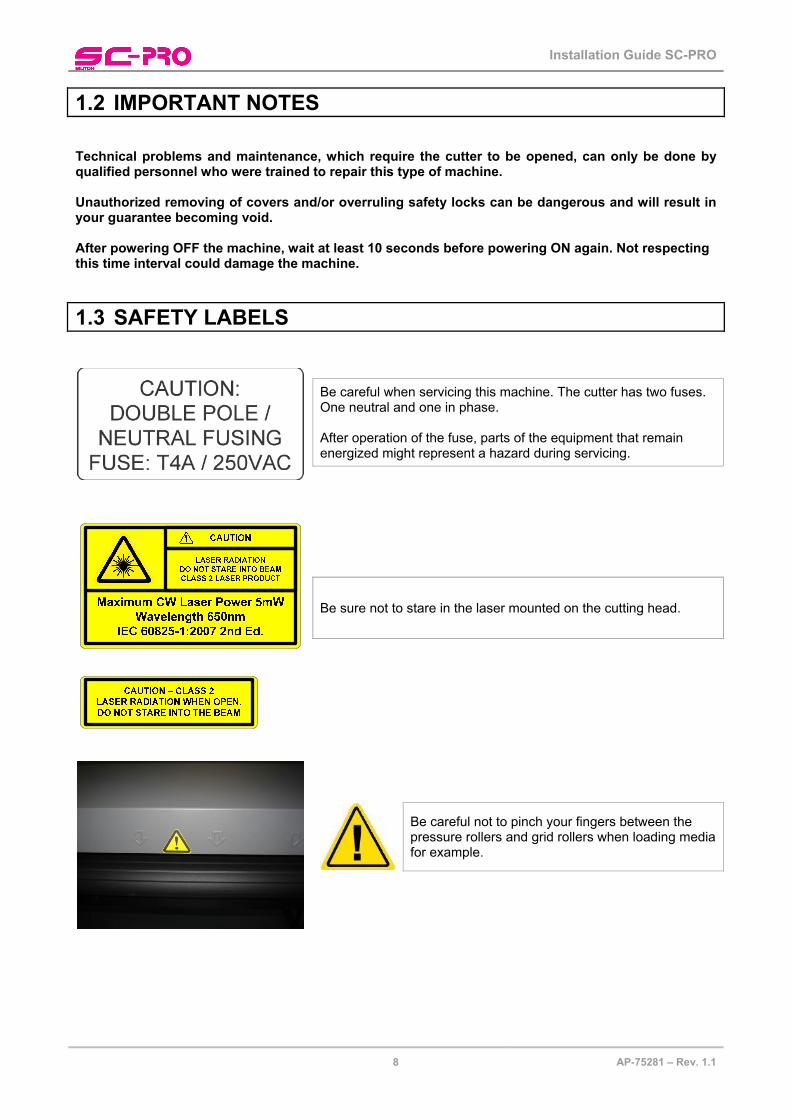
1.2 IMPORTANT NOTES Technical problems and maintenance, which require the cutter to be opened, can only be done by qualified personnel who were trained to repair this type of machine. Unauthorized removing of covers and/or overruling safety locks can be dangerous and will result in your guarantee becoming void. After powering OFF the machine, wait at least 10 seconds before powering ON again. Not respecting this time interval could damage the machine.
1.3 SAFETY LABELS
Be careful when servicing this machine. The cutter has two fuses. One neutral and one in phase. After operation of the fuse, parts of the equipment that remain energized might represent a hazard during servicing.
Be sure not to stare in the laser mounted on the cutting head.
Be careful not to pinch your fingers between the pressure rollers and grid rollers when loading media for example.
Installation Guide SC-PRO
9 AP-75281 – Rev. 1.1
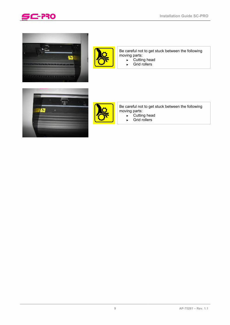
Be careful not to get stuck between the following moving parts:
► Cutting head ► Grid rollers
Be careful not to get stuck between the following moving parts:
► Cutting head ► Grid rollers

Installation Guide SC-PRO
10 AP-75281 – Rev. 1.1

Installation Guide SC-PRO
11 AP-75281 – Rev. 1.1
2 INSTALLATION ENVIRONMENT 2.1 DIMENSIONS Please find below the sizes of the SC Pro cutter with all dimensions in millimeters..
2305 1062
1259
662
2.2 INSTALLATION ENVIRONMENT REQUIREMENTS The location where you set up your equipment is very important. Please see to it that it meets following conditions:
Power supply
• 100 - 240 VAC • 50 - 60 Hz • Max. 1.5 A
Ambient Conditions:
Operating environment
• Temperature 5 °C to 30 °C • Humidity 35 % - 75 % non-condensing
Recommended environment (dark area)
• Temperature 16 °C to 25 °C • Humidity 50 % to 65 % non-condensing
Variation rate
• Temperature 2 °C per hour • Humidity 5 % per hour
Storage environment
• Temperature 0 °C to 50 °C

Installation Guide SC-PRO
12 AP-75281 – Rev. 1.1
Room conditions
• Please protect your cutter from moisture, dust, draughts and direct sunlight (to prevent possible media detection and epos readout issues). It is best to keep your machine away from open windows and air-conditioners.
• See to it that there is an adequate space around the cutter so that ventilation is not obstructed.
• Avoid unnecessary vibrations and set up your cutter on a level surface.
• Be sure to have some free space on each side of the SC-Pro to ease the operating of it.
a
b
c
d
a = at least 1 meter
b = at least 1 meter
c = at least 1 meter
d = at least 0,1 meter
• This means that you need the following room space in total: 3,20m x 2,66m (W x D)

Installation Guide SC-PRO
13 AP-75281 – Rev. 1.1
3 UNPACKING PROCEDURE
CAUTION
WHEN REMOVING THIS PRODUCT FROM THE PACKAGING BOX, ALWAYS REMOVE THE VINYL PLASTIC, AND HOLD ON THE SIDE OF THE PRODUCT. HOLDING THE UNIT OVER THE VINYL PLASTIC WRAPPING CAN RESULT IN SLIPPAGE AND DROPPING THE UNIT, RESULTING IN DAMAGE.
3.1 UNPACKING THE BOX
1
23
4
5678
9
10
11
Nr. Description 1 SC-Pro body 2 Front conveyor roll 3 Rear conveyor roll 4 Centre stand beam 5 Core with media bag 6 Centre bar bag assembly 7 Rear bar bag assembly 8 Front bar bag assembly 9 Installation kit 10 Box with stand 11 Box with 4 bag assembly bars
Installation Guide SC-PRO
14 AP-75281 – Rev. 1.1
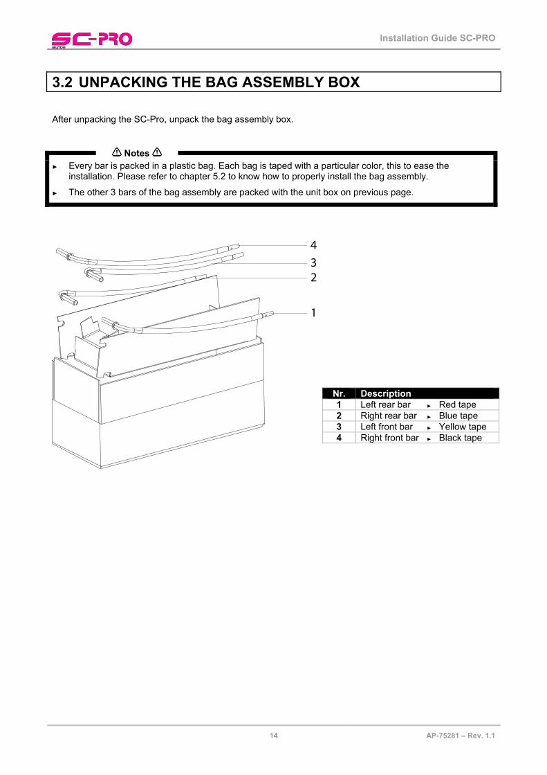
3.2 UNPACKING THE BAG ASSEMBLY BOX After unpacking the SC-Pro, unpack the bag assembly box.
Notes
► Every bar is packed in a plastic bag. Each bag is taped with a particular color, this to ease the installation. Please refer to chapter 5.2 to know how to properly install the bag assembly.
► The other 3 bars of the bag assembly are packed with the unit box on previous page.
1
234
Nr. Description 1 Left rear bar ► Red tape 2 Right rear bar ► Blue tape 3 Left front bar ► Yellow tape 4 Right front bar ► Black tape

Installation Guide SC-PRO
15 AP-75281 – Rev. 1.1
3.3 UNPACKING THE STAND ASSEMBLY BOX After unpacking the SC-Pro, unpack the stand assembly box.
Notes
► The centre stand beam is packed with the unit box as described above!
1
23
4
5
Nr. Description 1 Left stand leg 2 Right stand leg 3 Right foot assembly 4 Stand screw kit 5 Left foot assembly

Installation Guide SC-PRO
16 AP-75281 – Rev. 1.1

Installation Guide SC-PRO
17 AP-75281 – Rev. 1.1
4 VERIFICATION OF PACKAGED ITEMS After unpacking each box, inspect if there are no damaged parts and that all necessary parts are present.
NOTES
• THE CONTENTS OF THE PACKAGES MAY BE DIFFERENT DEPENDING ON THE MARKET WHERE THEY ARE USED. CONTACT YOUR LOCAL MUTOH DEALER OR DISTRIBUTOR FOR DETAILS.
• IF ANY PART IS MISSING OR BROKEN, CONTACT EITHER OF THE FOLLOWING: o THE SHOP WHERE YOU BOUGHT YOUR MUTOH CUTTER. o YOUR LOCAL MUTOH DISTRIBUTOR
(*) When ordered as a bundle together with a Mutoh Printer, the in-the-box software may be replaced with one software which handles cutting, printing and contour cutting.
Description Qty Cutter unit 1
Stand assembly 1
Media bag assembly 1
Conveyor system 1
Commercial kit 1 Tools 1
Knife holder and blade 1
Cutter blade 45° 1
Blade for auto sheet-off 1
Pressurized BallPoint Pen 1
Spare cutting mat 1
Mutoh knife 1
Core support 3” 2
Set of wing screws 1 Cables 1
Power cable EU 1
Power cable UK 1
Power cable US 1
USB cable 1
Adapter cable (9 – 25 pin) 1
Interface (RS-232) cable 1 Documentation 1
User’s Guide 1
Application Guide 1
Installation Guide 1
Installation Sheet 1
Installation CD 1
CD with manuals of all Mutoh machines 1
In-The-Box WEEE regularisation 1
Starter software kit (*) 1
Quality test sheet of this machine 1

Installation Guide SC-PRO
18 AP-75281 – Rev. 1.1

Installation Guide SC-PRO
19 AP-75281 – Rev. 1.1
5 ASSEMBLING THE UNIT 5.1 ASSEMBLING THE STAND Assemble the stand as drawn below. Use the hexagon key with hand grip to tighten all the screws.
FRONT
REAR
FRONTREAR
1
2
3
N° Description Qty 1 Plain washer M8 8 2 Spring washer M8 8 3 Hexagon screw M8x16 8
Installation Guide SC-PRO
20 AP-75281 – Rev. 1.1
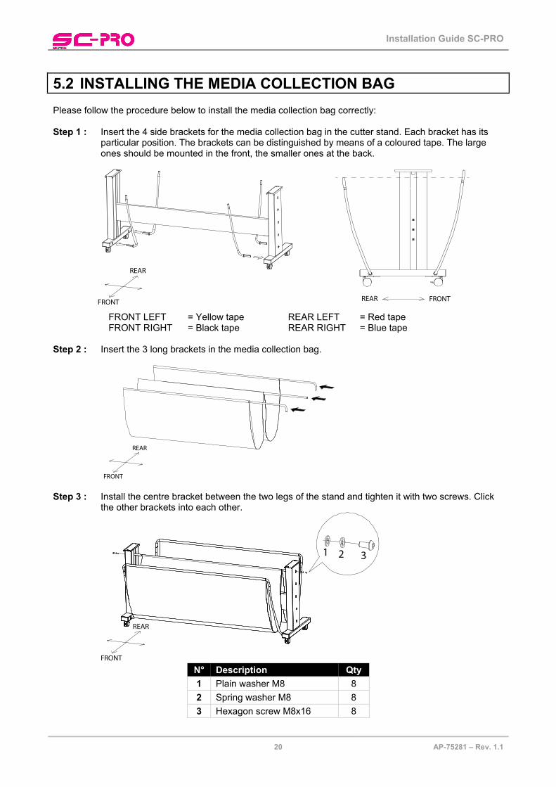
5.2 INSTALLING THE MEDIA COLLECTION BAG Please follow the procedure below to install the media collection bag correctly: Step 1 : Insert the 4 side brackets for the media collection bag in the cutter stand. Each bracket has its
particular position. The brackets can be distinguished by means of a coloured tape. The large ones should be mounted in the front, the smaller ones at the back.
FRONT
REAR
FRONTREAR
FRONT LEFT = Yellow tape REAR LEFT = Red tape FRONT RIGHT = Black tape REAR RIGHT = Blue tape
Step 2 : Insert the 3 long brackets in the media collection bag.
FRONT
REAR
Step 3 : Install the centre bracket between the two legs of the stand and tighten it with two screws. Click
the other brackets into each other.
FRONT
REAR
1 2 3
N° Description Qty 1 Plain washer M8 8 2 Spring washer M8 8 3 Hexagon screw M8x16 8

Installation Guide SC-PRO
21 AP-75281 – Rev. 1.1
5.3 INSTALLING THE CUTTER ON THE STAND Step 1 : Position the cutter body on the stand with at least 4 people.
Be sure that the 4 positioning tabs are installed in the holes.
Tighten the body to the stand with four screws using the L shaped hexagon key.
FRONT
REAR
123
N° Description Qty 1 Plain washer M8 8 2 Spring washer M8 8 3 Hexagon screw M8x16 8
Step 2 : If the cutter does not fit perfectly on the stand, loosen the stand screws a bit. Now it should be
possible to mount the cutter on the stand.
FRONT
REAR
1
2
3
Step 3 : Tighten the loosened screws of the stand again.

Installation Guide SC-PRO
22 AP-75281 – Rev. 1.1
5.4 REMOVING THE PROTECTIVE MATERIALS To avoid damage during transport, buffers have been installed. Be sure to remove them before start operating.
Head buffers
Lever wing screw
Installation Guide SC-PRO
23 AP-75281 – Rev. 1.1
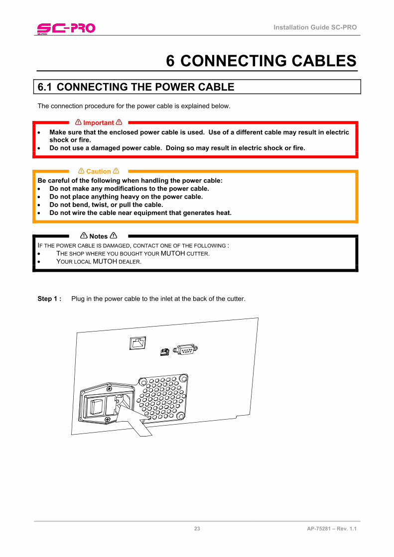
6 CONNECTING CABLES 6.1 CONNECTING THE POWER CABLE The connection procedure for the power cable is explained below.
Important
• Make sure that the enclosed power cable is used. Use of a different cable may result in electric shock or fire.
• Do not use a damaged power cable. Doing so may result in electric shock or fire.
Caution
Be careful of the following when handling the power cable: • Do not make any modifications to the power cable. • Do not place anything heavy on the power cable. • Do not bend, twist, or pull the cable. • Do not wire the cable near equipment that generates heat.
Notes
IF THE POWER CABLE IS DAMAGED, CONTACT ONE OF THE FOLLOWING : • THE SHOP WHERE YOU BOUGHT YOUR MUTOH CUTTER. • YOUR LOCAL MUTOH DEALER.
Step 1 : Plug in the power cable to the inlet at the back of the cutter.

Installation Guide SC-PRO
24 AP-75281 – Rev. 1.1
Step 2 : Plug it in the power cable to the outlet
Important
• DO NOT ATTEMPT TO PLUG IN ELECTRICAL PLUGS WITH WET HANDS. DOING SO MAY RESULT IN ELECTRICAL SHOCK.
• BE SURE TO USE THE SPECIFIED VOLTAGE (AC 100V-120V/220V-240V). OTHERWISE, ELECTRICAL SHOCK OR FIRE MAY OCCUR.
• USE ELECTRICITY DIRECTLY FROM A POWER OUTLET (AC 100V-120V/220V-240V). DO NOT PUT MANY LOADS ON ONE ELECTRICAL OUTPUT. OTHERWISE, HEAT MAY BE GENERATED AND CAUSE FIRE.
• BE SURE TO USE AN OUTLET WITH AN EARTH TERMINAL, AND USE THE TERMINAL CORRECTLY. OTHERWISE, ELECTRICAL SHOCK OR FIRE MAY OCCUR.
• DO NOT CONNECT EARTH CABLES IN THE FOLLOWING AREAS : ► GAS PIPES. DOING SO MAY CAUSE FIRE OR AN EXPLOSION. ► EARTH TERMINALS FOR TELEPHONE LINES OR LIGHTNING RODS. DOING SO MAY CAUSE A LARGE FLOW
OF VOLTAGE IF LIGHTNING OCCURS. ► WATER PIPES OR FAUCETS. IF THERE IS A PLASTIC PART IN THE PIPE, THE EARTH WILL NOT WORK
CORRECTLY.
Caution
• FOLLOW THE INSTRUCTIONS BELOW WHEN HANDLING THE POWER PLUG. OTHERWISE, FIRE MAY OCCUR. ► WIPE AWAY DUST AND ANY OTHER RESIDUE BEFORE INSERTING THE PLUG. ► ENSURE THAT THE PLUG IS FIRMLY INSERTED AS FAR AS IT WILL GO.
• ENSURE THAT THE PLUG HAS BEEN DISCONNECTED FROM THE POWER SOCKET WHEN IT IS NOT USED FOR A LONG TIME.
• EARTH WIRES MUST BE CONNECTED TO WIRES OR TERMINALS THAT FULFIL THE CONDITIONS : ► EARTH TERMINALS OF POWER SOCKET ► EARTH WIRES WITH COPPER MORSEL THAT IS AT LEAST 650 MM UNDER GROUND
Notes
• IF YOU CANNOT USE EARTH TERMINALS OR FIND ANY OF THEM, CONTACT THE SHOP WHERE YOU BOUGHT YOUR CUTTER.
• DO NOT UNPLUG THE POWER CABLE WHEN THE CUTTER IS ON. IF THE POWER CABLE HAS BEEN UNPLUGGED, LEAVE THE CUTTER FOR AT LEAST 1 MINUTE BEFORE PLUGGING THE CABLE IN AGAIN.

Installation Guide SC-PRO
25 AP-75281 – Rev. 1.1
6.2 CONNECTING THE CUTTER TO A COMPUTER To make the connection between the cutter and the computer, there are 3 possibilities:
► 2-way RS-232C serial interface ► USB interface ► Ethernet/Network connection
6.2.1 Serial Interface The serial RS-232C interface enables the cutter to be connected to and controlled by an RS-232C compatible host computer system. The cutter is equipped with a standard RS-232C - DB-9P connector on the rear panel and requires a standard RS-232C DB-9S mating connector. Step 1 : Make sure both the cutter and the computer are turned off. Connect one end of the serial
interface cable to the serial interface connector at the rear side of the cutting plotter.
Step 2 : Fasten the screws to secure the connector. Step 3 : Connect the other end of the serial cable to your computer.
Notes
For proper operation of the serial communication, it will be necessary to match the computer settings to the plotter settings!
9 pin 25 pin 25 pin 9 pin

Installation Guide SC-PRO
26 AP-75281 – Rev. 1.1
6.2.2 USB interface Step 1 : Make sure the USB driver has been installed as described further on. Step 2 : Connect one end of the USB cable to the USB connector at the rear side of the cutting plotter.
Step 3 : Connect the other end of the USB cable to your computer.
Notes
The serial and USB communication is bi-directional. Your cutting plotter receives data from the computer and sends back information to the computer.
6.2.3 Ethernet/Network connection Step 1 : Make sure the CPR manager (com port redirector) has been installed as described further on. Step 2 : Connect one end of the network cable to the network interface at the rear side of the cutting
plotter.
Step 3 : Connect the other end of the network cable to your network.

Installation Guide SC-PRO
27 AP-75281 – Rev. 1.1
7 CUTTER SOFTWARE INSTALLATION Before you will be able to perform a first cutting job with the SC Pro, several drivers and software needs to be installed. Some of them are obligatory, recommended and optional. Please find below an overview of all the available firmware / drivers and their importance. Install them in the same order! All drivers are collected on an installation CD. Please refer to this CD to know how to install the drivers correctly. 1. Computer software
► Cutter driver / software OBLIGATORY Installation CD
► USB driver RECOMMENDED Installation CD
► Ethernet driver (CPR manager) OPTIONAL Installation CD
► Mutoh Cut server RECOMMENDED Installation CD
2. Embedded software
► Install latest firmware version RECOMMENDED If latest firmware has not been installed. ► Keyboard firmware update OBLIGATORY Only when there is a new version

Installation Guide SC-PRO
28 AP-75281 – Rev. 1.1
3. Compatibility list
Operating system Function Connection type
Via serial cable Via USB cable Via Ethernet cable(virtual com)
Windows 98
Cutting Firmware update
CutServer
Windows XP
Cutting Firmware update
CutServer
Windows Vista 32 bit
Cutting Firmware update
CutServer
Windows Vista 64 bit
Cutting Firmware update
CutServer
MAC OSX
Cutting (*)
Firmware update CutServer
MAC OS9
Cutting (*)
Firmware update CutServer
Linux
Cutting Firmware update
CutServer
CutSoftware
Possibility to sent data via
Serial Cable USB Cable Ethernet cable
Virtual COM port Directly TCP/IP
Caldera EasySIGN
(**) FlexiSign Aurelon
(*) With an USB2 - serial converter cable (**) As from service pack 5.05 – 5.0.6.7

Installation Guide SC-PRO
29 AP-75281 – Rev. 1.1
8 INSTALLING AND REPLACING TOOLS 8.1 INSTALLING TOOLS At the right-hand side of the cutter head, you will find a pivoting mounting bracket. Opening this bracket will enable you to install a full range of cutting and drawing tools. To do so, please follow the instructions mentioned below. Step 1 : Open the screw (1) to unlock the tool head-mounting bracket. Step 2 : Hold back the clip (2) of the tool head and slide the tool into position, making sure the tool collar
fits into the groove just beneath the locking screw (3). Step 3 : Fasten the screw to secure the tool into position.
Installation Guide SC-PRO
30 AP-75281 – Rev. 1.1
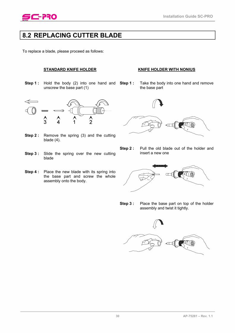
8.2 REPLACING CUTTER BLADE To replace a blade, please proceed as follows:
STANDARD KNIFE HOLDER
Step 1 : Hold the body (2) into one hand and unscrew the base part (1)
Step 2 : Remove the spring (3) and the cutting
blade (4). Step 3 : Slide the spring over the new cutting
blade Step 4 : Place the new blade with its spring into
the base part and screw the whole assembly onto the body.
KNIFE HOLDER WITH NONIUS
Step 1 : Take the body into one hand and remove the base part
Step 2 : Pull the old blade out of the holder and
insert a new one
Step 3 : Place the base part on top of the holder
assembly and twist it tightly.

Installation Guide SC-PRO
31 AP-75281 – Rev. 1.1
8.3 REPLACING AUTO SHEET-OFF KNIFE When you frequently use the auto-sheet-off utility, it is a good practice to regularly clean the knife and to replace it when it starts to wear. To replace the auto sheet-off knife, please follow the instructions mentioned below. Step 1 : Power OFF the unit and remove the power cable. Step 2 : Higher the cutter cap (1) and swing it away (2). Do not loosen the spring.
Step 3 : Remove the sheet-off knife (3). Step 4 : Clean the sheet-off knife, removing any material residues that might be clogged to the blade. In
case the blade is worn, reinstall a new knife. Step 5 : Place the (new) knife into the auto sheet-off assembly (4). Make sure the knife is correctly
oriented. Step 6 : Reinstall the cutter cap onto the auto sheet-off knife. Step 7 : Reinstall the head cover.

Installation Guide SC-PRO
32 AP-75281 – Rev. 1.1

Installation Guide SC-PRO
33 AP-75281 – Rev. 1.1
9 LOADING MEDIA 9.1 SHEET MEDIA Configuration to start from:
► Raised pressure rollers. ► Remove conveyor rolls. ► Rear media collection bag open and EMPTY. ► Front media collection bag open when the cut job is smaller than 4m.
Front media collection bag closed when the cut job is larger than 4m. Step 1 : Guide the media under the pressure rollers at the front of the cutter.
Step 2 : Position the sheet paying attention to the following:
► The outer left and the outer right pressure rollers always have to be used. The middle rollers 2 and 3 (half of the pressure as roller 1 and 4) can be used, but they may also be disabled (in between two arrows (as number 2 on the picture below). This to eliminate roller marks on vulnerable vinyl for example. The left pressure roller can only move between the two flat arrows.
► The cutter will cut between the centres of the outer pressure rollers, regardless of the width of the cut vinyl. Therefore, it is recommended to position the outer pressure rollers about 1cm inside the media. It is not recommended that the rollers run on the very edge of the material.
Step 3 : Position the pressure rollers as you have decided in step 2. Pressure rollers 2-3-4 have a tactile and audible click system which makes it easier to position them correctly. The right pressure roller (1) can never be malpositioned.
If one of the others is malpositioned, a message will be displayed after media initialization. Please refer to the picture.
FRONT of the machine
1234
Pressure roll 3malpositioned!
Step 4 : Set the media type to sheet:

Installation Guide SC-PRO
34 AP-75281 – Rev. 1.1
Step 5 : Make sure that about half of the sheet hangs in front of the machine and half hangs at the back. This will make it easier to align the media correctly.
Step 6 : Load the media straight. To help you, two rulers are attached to the front platen.
Step 7 : Be sure that the media is cut off straight at the front to avoid media initialization mismatches. Step 8 : Be sure that the set maximum sheet length is smaller than the actual length of the loaded sheet.
If not, the cutter will automatically swap from sheet to roll mode.
Max Sheet Length 2000 [mm] Save: Exit:
Notes
Before lowering the pressure rollers, be sure that there is a knife or pen installed in the head. This because during the media initialization, the penhead will also be initialized. If you insert a pen/knife afterwards, the machine will not know how to excite the coil of the penhead. This could result in cutting lines across the complete print.
Step 9 : Lower the lever.
Notes
the head will move fastly over the media. Be carefull not to pinch your fingers during this action.
Step 10 : The cutter will measure the paper and will feed the set pre-feed length. The following message
will be displayed:
Sheet
Please wait
Notes
Please refer to “chapter 4 - Pre-feed Length” to understand the important function of this feature.
Step 11 : When no problems occur, the main screen will appear. The measured width of the media will be
displayed:
*READY*X 950 Y 500 X = Media length in mm Drag Knife Tool Y = Media width in mm 60 cm/s 100 g
Step 12 : You are ready to cut.
Installation Guide SC-PRO
35 AP-75281 – Rev. 1.1
9.2 ROLL MEDIA Please follow the procedure below to load roll media properly.
Be aware that there is a loading cycle difference between loading cut vinyl and pre-printed vinyl meant for contour cutting.
9.2.1 Loading cut vinyl Configuration to start from:
► Raised pressure rollers. ► Rear media collection bag open and EMPTY. ► Front media collection bag open when the cut job is smaller than 4m.
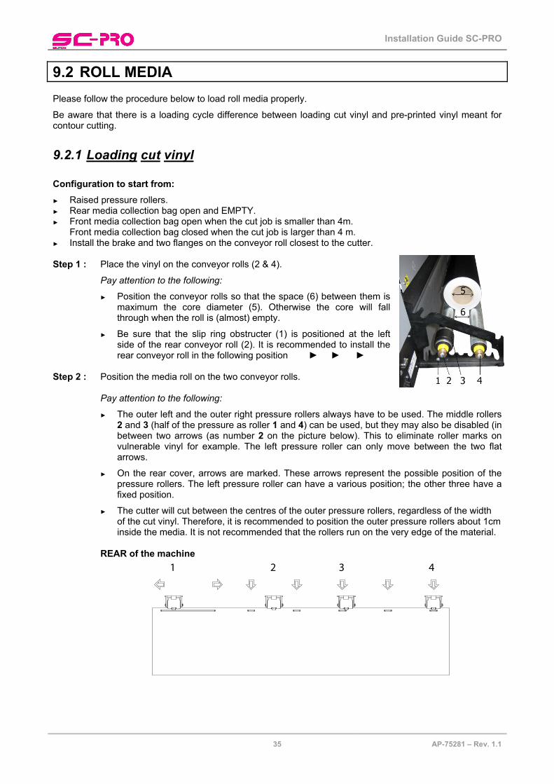
Front media collection bag closed when the cut job is larger than 4 m. ► Install the brake and two flanges on the conveyor roll closest to the cutter. Step 1 : Place the vinyl on the conveyor rolls (2 & 4).
Pay attention to the following:
► Position the conveyor rolls so that the space (6) between them is maximum the core diameter (5). Otherwise the core will fall through when the roll is (almost) empty.
► Be sure that the slip ring obstructer (1) is positioned at the left side of the rear conveyor roll (2). It is recommended to install the rear conveyor roll in the following position ► ► ►
Step 2 : Position the media roll on the two conveyor rolls.
Pay attention to the following:
► The outer left and the outer right pressure rollers always have to be used. The middle rollers 2 and 3 (half of the pressure as roller 1 and 4) can be used, but they may also be disabled (in between two arrows (as number 2 on the picture below). This to eliminate roller marks on vulnerable vinyl for example. The left pressure roller can only move between the two flat arrows.
► On the rear cover, arrows are marked. These arrows represent the possible position of the pressure rollers. The left pressure roller can have a various position; the other three have a fixed position.
► The cutter will cut between the centres of the outer pressure rollers, regardless of the width of the cut vinyl. Therefore, it is recommended to position the outer pressure rollers about 1cm inside the media. It is not recommended that the rollers run on the very edge of the material.
REAR of the machine
1 2 3 4

Installation Guide SC-PRO
36 AP-75281 – Rev. 1.1
Step 3 : Guide the media under the pressure rollers to the front of the cutter. Step 4 : Position the pressure rollers as you have decided in step 2. Pressure rollers 2-3-4 have a tactile
and audible click system which makes it easier to position them correctly. The right pressure roller (1) can never be malpositioned.
If one of the others is malpositioned, a message will be displayed after media initialization. Please refer to the picture.
FRONT of the machine
1234
Pressure roll 3malpositioned!
Step 5 : Set the media load type prior to loading media. Select if you want the cutting plotter to look for the
front edge of the vinyl. ► ROLL front The cutter will measure the left, right and front of the media.
The origin will be defined from the front of the roll.
There will be a shuffle of the set Pre-Feed length. ► ROLL The cutter will measure the left and right side of the media.
The origin will be defined from the position of the roll when lowering the lever.
There will be a shuffle of the set Pre-Feed length.
Step 6 : Load the media properly:
It is best that you hold the front edge of the media in the middle with one hand and with the other hand the roll itself.
As you are holding the roll firmly into position, pull the front edge of the media forward so that there is an even tension across the whole width of the roll (= equal tension method)
Do NOT use the rulers to align a roll of media! They are for use with sheets only. Rolls can only be correctly installed using the equal tension method.
The rulers will help you monitoring if the media is not meandering too much.
Installation Guide SC-PRO
37 AP-75281 – Rev. 1.1
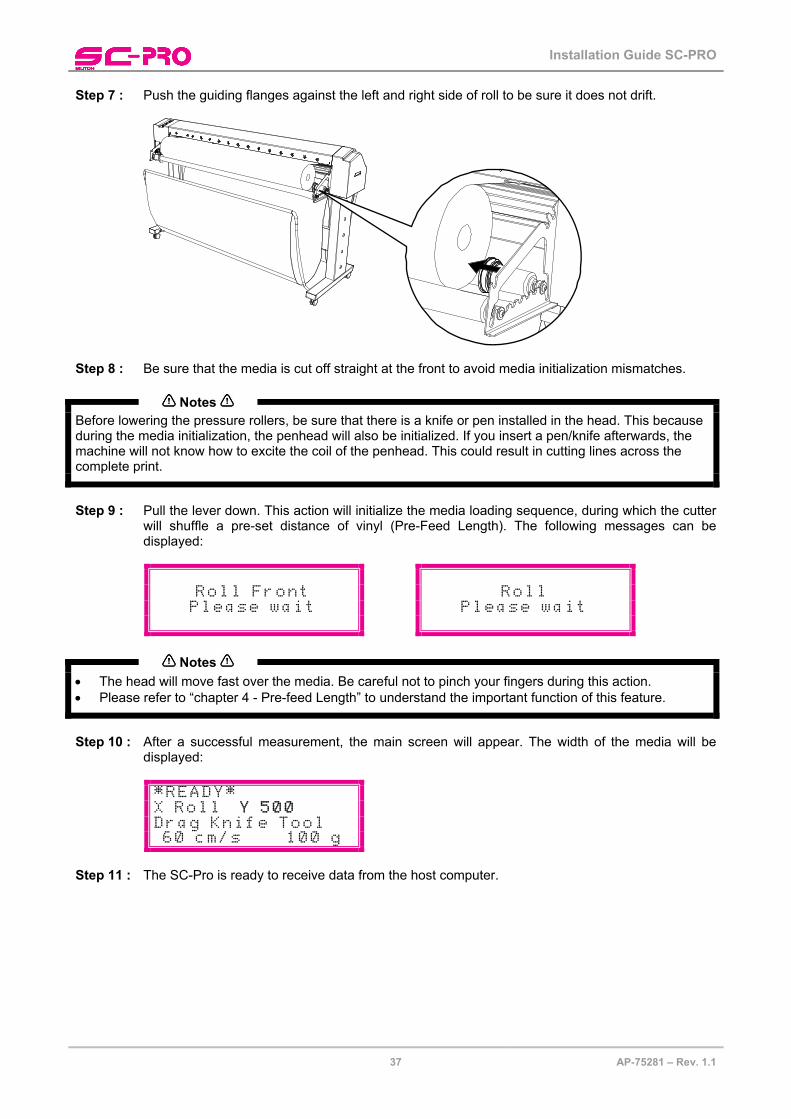
Step 7 : Push the guiding flanges against the left and right side of roll to be sure it does not drift.
Step 8 : Be sure that the media is cut off straight at the front to avoid media initialization mismatches.
Notes
Before lowering the pressure rollers, be sure that there is a knife or pen installed in the head. This because during the media initialization, the penhead will also be initialized. If you insert a pen/knife afterwards, the machine will not know how to excite the coil of the penhead. This could result in cutting lines across the complete print.
Step 9 : Pull the lever down. This action will initialize the media loading sequence, during which the cutter
will shuffle a pre-set distance of vinyl (Pre-Feed Length). The following messages can be displayed:
Roll Front Roll Please wait Please wait
Notes
• The head will move fast over the media. Be careful not to pinch your fingers during this action. • Please refer to “chapter 4 - Pre-feed Length” to understand the important function of this feature.
Step 10 : After a successful measurement, the main screen will appear. The width of the media will be
displayed:
*READY*X Roll Y 500 Drag Knife Tool 60 cm/s 100 g
Step 11 : The SC-Pro is ready to receive data from the host computer.

Installation Guide SC-PRO
38 AP-75281 – Rev. 1.1
9.2.2 Loading pre-printed vinyl Configuration to start from:
► Raised pressure rollers. ► Rear media collection bag open and EMPTY. ► Front media collection bag open when the cut job is smaller than 4m.
Front media collection bag closed when the cut job is larger than 4 m. ► Install the brake and two 3” cones on the conveyor roll closest to the cutter. Step 1 : Install the vinyl between the two 3” cones but do not fix the cones already. Step 2 : Position the pre-printed vinyl on the conveyor roll.
Pay attention to the following:
► The outer left and the outer right pressure rollers always have to be used. The middle rollers 2 and 3 (half of the pressure as roller 1 and 4) can be used, but they may also be disabled (in between two arrows (as number 2 on the picture below). This to eliminate roller marks on vulnerable vinyl for example. The left pressure roller can only move between the two flat arrows.
► On the rear cover, arrows are marked. These arrows represent the possible position of the pressure rollers. The left pressure roller can have a various position; the other three have a fixed position.
► The cutter will cut between the centres of the outer pressure rollers, regardless of the width of the cut vinyl. Therefore, it is recommended to position the outer pressure rollers about 1cm inside the media. It is not recommended that the rollers run on the very edge of the material.
REAR of the machine
Step 3 : Lock the 3” cones with one screw each. Step 4 : Guide the media under the pressure rollers to the front of the cutter on one of the two following
possibilities:
1 2 3
It is recommended to load the media as shown on picture 1. If the vinyl touches the core as on picture 2, load the media as on picture 3.
1 2 3 4
Installation Guide SC-PRO
39 AP-75281 – Rev. 1.1
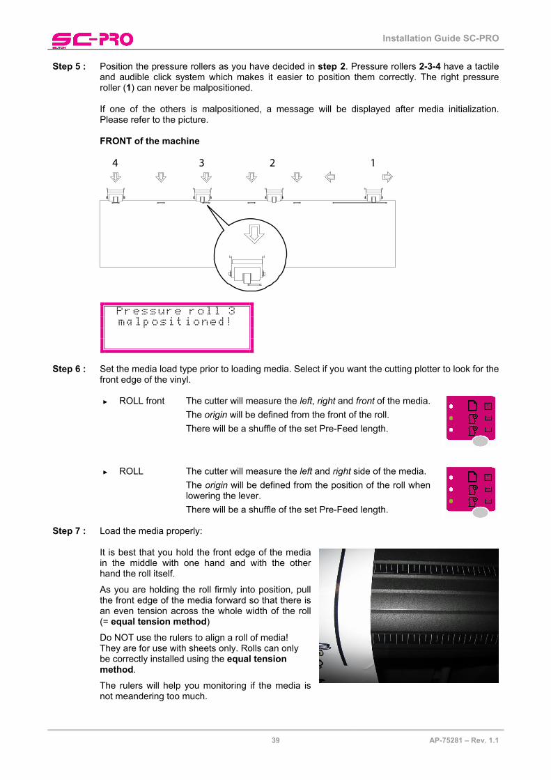
Step 5 : Position the pressure rollers as you have decided in step 2. Pressure rollers 2-3-4 have a tactile and audible click system which makes it easier to position them correctly. The right pressure roller (1) can never be malpositioned.
If one of the others is malpositioned, a message will be displayed after media initialization. Please refer to the picture.
FRONT of the machine
1234
Pressure roll 3malpositioned!
Step 6 : Set the media load type prior to loading media. Select if you want the cutting plotter to look for the
front edge of the vinyl. ► ROLL front The cutter will measure the left, right and front of the media.
The origin will be defined from the front of the roll.
There will be a shuffle of the set Pre-Feed length. ► ROLL The cutter will measure the left and right side of the media.
The origin will be defined from the position of the roll when lowering the lever.
There will be a shuffle of the set Pre-Feed length.
Step 7 : Load the media properly:
It is best that you hold the front edge of the media in the middle with one hand and with the other hand the roll itself.
As you are holding the roll firmly into position, pull the front edge of the media forward so that there is an even tension across the whole width of the roll (= equal tension method)
Do NOT use the rulers to align a roll of media! They are for use with sheets only. Rolls can only be correctly installed using the equal tension method.
The rulers will help you monitoring if the media is not meandering too much.
Installation Guide SC-PRO
40 AP-75281 – Rev. 1.1
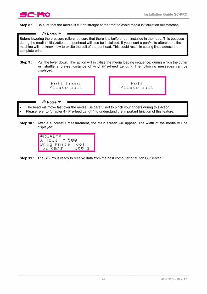
Step 8 : Be sure that the media is cut off straight at the front to avoid media initialization mismatches.
Notes
Before lowering the pressure rollers, be sure that there is a knife or pen installed in the head. This because during the media initialization, the penhead will also be initialized. If you insert a pen/knife afterwards, the machine will not know how to excite the coil of the penhead. This could result in cutting lines across the complete print.
Step 9 : Pull the lever down. This action will initialize the media loading sequence, during which the cutter
will shuffle a pre-set distance of vinyl (Pre-Feed Length). The following messages can be displayed:
Roll front Roll Please wait Please wait
Notes
• The head will move fast over the media. Be careful not to pinch your fingers during this action. • Please refer to “chapter 4 - Pre-feed Length” to understand the important function of this feature.
Step 10 : After a successful measurement, the main screen will appear. The width of the media will be
displayed:
*READY*X Roll Y 500 Drag Knife Tool 60 cm/s 100 g
Step 11 : The SC-Pro is ready to receive data from the host computer or Mutoh CutServer.

Installation Guide SC-PRO
41 AP-75281 – Rev. 1.1
325 mm
445 mm
10 CALIBRATING THE CUTTER To be able to contour cut, an Epos® feature has been incorporated. This feature will search for the Reference box and measure the position of the design(s). When you establish some miscalculations during contour cutting, it is recommended to perform the test cuts described below. 10.1.1 EPOS alignment 10.1.1.1 Tools necessary: ► SC-Pro.
► Host Computer with the Mutoh CutServer installed on.
► EPOS final check chart pre-printed on vinyl or paper.
► Drag knife when testing on vinyl.
► Pressurized ballpoint pen when testing on paper. 10.1.1.2 Alignment procedure Step 1 : Load the appropriate tool (a knife on vinyl and a pen on
paper). Step 2 : Power ON the cutter and be sure that the lever is raised. Step 3 : Press the [TOOL] button and set the tool you are using.
Tool Pen Start: Exit:
ToolKnife
Start: Exit:
Step 4 : Set the media type to “Sheet”.
Step 5 : Insert the test sheet as described in the chapter “Loading sheet media” with the arrow in the top
right corner and the outer pressure rollers outside the reference box. The middle pressure rollers may be disabled.
Step 6 : Pull the lever down. Step 7 : Set your speed and force values accordingly. Step 8 : Make sure there is a connection between the Mutoh CutServer and the cutter.

Installation Guide SC-PRO
42 AP-75281 – Rev. 1.1
Step 9 : Launch the job in one of the two possible ways: a. Directly from the SC-Pro keyboard
1. Press the contour button key and select BarCode Single – Single Scan.
Contourcutting Barcode Single Barcode MultiStart Next:
ContourcuttingSingle scan Multi scan
Start: Exit:
2. Press the [ ]-key to start the test.
b. Using the Mutoh CutServer
1. Make a connection with the cutter by enabling the checkmark. 2. Make following settings: Single Scan – Single Frame Mode and Save Settings.
3. Press the [GO] button to start the test.
Step 10 : The reference box will be automatically measured and the barcode verification will be executed.
When the plot file is not listed in the Mutoh CutServer, the CutServer Epos Final Check plot file will be used.
Step 11 : The pre-printed contour data will be replot. Step 12 : Verify the positioning of you contour plot data. 10.1.1.3 Adjustments if necessary It might be possible that the contour positioning is not correctly. Please perform the following extra tests to optimize it: 1. Recalibrate your laser beam by means of the Epos Calibration test as described in the next chapter. 2. Verify your X-Y lengths via the Mutoh CutServer (SC-Pro Tests menu)

Installation Guide SC-PRO
43 AP-75281 – Rev. 1.1
10.1.2 EPOS calibration This test will fine-tune the position of the cutting knife compared to the EPOS laser firmware wisely. This test can be done manually and automatically. It is recommended however, to let the SC-Pro adjust the values automatically. Step 1 : Install and set a knife. Step 2 : Install a dark (black) vinyl. Check with the EPOS readout function if it is dark enough. Step 3 : Press the [TEST]-key.
Step 4 : Select “EPOS calibration” with the - keys.
Test EPOS calibrate METHOD: <TEST> To start:
Step 5 : Press the [TEST]-key once again to decide whether to perform the test automatically or manually.
EPOS calibrate Manual 30 cm/s 120 g To start:
Step 6 : Move the cutter head with the arrow keys to the centre of the media and feed it a bit to be sure
you have enough space (10 cm x 10 cm) for the test. Step 7 : Press the [ ] key to start the calibration.
► MANUAL CALIBRATION
o Be sure that you have set an origin. o Following pattern will be cut:

Installation Guide SC-PRO
44 AP-75281 – Rev. 1.1
o Press the [ ] key.
o The following message will be displayed:
Please weed out
The square(s) &press any key
o Weed out the two rectangles.
o Press any key.
o The EPOS laser will move to the centre of the cross while following message is displayed:
*EPOS CALIBRAT.*Move laser
pointer to crossand press
o Move the EPOS laser using the – keys to the centre (if necessary) and press the
[ ] key to confirm.

Installation Guide SC-PRO
45 AP-75281 – Rev. 1.1
► AUTOMATIC CALIBRATION
o Following pattern will be cut:
o Press the [ ] key.
o The following message will be displayed:
Please weed out
The square(s) &press any key
o Weed out the rectangle.
o Press any key.
o The cutter will automatically measure the bottom and right side of the box, this to know the position of the knife compared to the EPOS laser.
EPOSCalibration
DONE
Step 8 : The EPOS calibration has finished.

Installation Guide SC-PRO
46 AP-75281 – Rev. 1.1
10.1.3 XY-Distance Accuracy
The XY - Distance Accuracy tests are developed to check the actual X-Y cutting distance with the sent vector data.
Please follow the procedure below to make the test:
Step 1 : Open Mutoh’s CutServer
Step 2 : Select which test to perform.
Step 3 : Select the appropriate COM-port and double-click.
Step 4 : Load a roll or sheet with at least the measurements indicated in the dropdown menu.
Step 5 : Load a knife.
Step 6 : A box will be cut.
Step 7 : Peel out the box.
Step 8 : Measure the X length and Y width and enter them. Be sure to enter the values in mm!
Step 9 : If the correct values have been entered, the following message will appear and the test will be done.
