apco flanges - pipes nz ltd · api 605 flanges are designated series b flanges in asme b16.47. 3 bs...
TRANSCRIPT


APCO Flanges
1APCO Tel: 86-431-88546619 Fax: 86-431-88546621 E-mail: [email protected]
Section 8
Flanges
This section contains extracts from American and Britishspecifications applicable to forged steel flanges.
Subsections and topics PagesFlanges - General Information 2ASME/ANSI Flanges (incl. MSS SP-44 and API 605) 4Weld Neck Flanges - Welding Ends (ASME/ANSI) 5Ring Joint Facings - ASME/ANSI B16.5 & B16.47 6Weld Neck Flanges - ANSI B16.5 10, 46Slip On Flanges - ANSI B16.5 17Blind Flanges - ANSI B16.5 & ASME B16.47 (MSS SP-44) 24, 46Lap Joint Flanges - ANSI B16.5 32Threaded Flanges - ANSI B16.5 39BS 3293 Flanges (Weld Neck and Slip On > NPS 26) 55BS 4504 Circular Flanges - General 60Weld Neck Flange - Welding Ends 62Flange Facings - BS 4504 62Flange Drilling Details - BS 4504 64Plate Flanges (Code 101) - BS 4504 65Weld Neck Flanges (Code 111) - BS 4504 66Slip On Flanges (Code 112) - BS 4504 68Threaded Flanges (Code 113) - BS 4504 69Blank Flanges (Code 105) - BS 4504 70BS 10 Flanges 71Pressure/Temperature Ratings (ASME/ANSI) 73
Specifications covered in this Section PageASME B16.5-1996 - Pipe Flanges and Flanged FittingsNPS 1/2 through NP 24
4(general)10 to 45
ASME B16.47-1996 - Large Diameter Steel FlangesNPS 26 through NPS 60(Covers MSS SP-44 and API 605 flanges)
4(general)46 to 54
MSS SP-44 1996 - Edition, Steel Pipeline Flanges(Covered by ASME B16.47-1996 Series A) 46 to 50
API Standard 605 - Cancelled(Covered by ASME B16.47-1996 Series B) 51 to 54
BS 10 : 1962 - Specification for Flanges and Bolting forPipes, Valves, and Fittings 71
BS 3293 : 1960 (incorporating amendment 1972) -Specification for Carbon Steel Pipe Flanges (over 24 inches nominal size) for the Petroleum Industry
55
BS 4504 : Section 3.1 : 1989 (incorporating amendments) -Circular Flanges for Pipes, Valves and Fittings (PN designated), Section 3.1 Specification for Steel Flanges
60
ISO 7005-1 : 1992 (E), Metallic Flanges - Part 1: SteelFlanges (this is substantially the same as BS 4504) 60

APCO Flanges
2 APCO Tel: 86-431-88546619 Fax: 86-431-88546621 E-mail: [email protected]
Flanges - General Information
A Flange is a method of connecting pipes, valves, pumps and other equipment to form a pipework system. It also provides easy access for cleaning, inspection or modification. Flanges are usually welded or screwed into such systems and then joined with bolts.
Flange Types
This flange is circumferentially welded into the system at its neck which means that the integrity of the butt welded area can be easily examined by radiography. The bores of both pipe and flange match, which reduces turbulence and erosion inside the pipeline. The weld neck is therefore favoured in critical applications
This flange is slipped over the pipe and then fillet welded. Slip-on flanges are easy to use in fabricated applications.
This flange is used to blank off pipelines, valves and pumps, it can also be used as an inspection cover. It is sometimes referred to as a blanking flange.
This flange is counter bored to accept the pipe before being fillet welded. The bore of the pipe and flange are both the same therefore giving good flow characteristics.
This flange is referred to as either threaded or screwed. It is used to connect other threaded components in low pressure, non-critical applications. No welding is required.
These flanges are always used with either a stub end or taft which is butt welded to the pipe with the flange loose behind it. This means the stub end or taft always makes the face. The lap joint is favoured in low pressure applications because it is easily assembled and aligned. To reduce cost these flanges can be supplied without a hub and/or in treated, coated carbon steel.
This is a method of ensuring leak proof flange connection at high pressures. A metal ring is compressed into a hexagonal groove on the face of the flange to make the seal. This jointing method can be employed on Weld Neck, Slip-on and Blind Flanges.

3 APCO Tel: 86-431-88546619 Fax: 86-431-88546621 E-mail: [email protected]
APCO Flanges
Flanges - General Information
Specifications
Refer to page 1 for a list of flange specifications (with page references) covered in this Section.
Manufacture Summary of materials used for flanges
ASME/ ANSI B16.5
ASME B16.47 Series A
(or MSS SP-441)
ASME B16.47 Series B
( or API 6052) BS
4504 BS
3293
BS 103
Forging (ASTM A 182) ✔ ✔ ✔ ✔ ✔ ✔
Plate (ASTM A 240)4 ✔ ✔ ✔
Bar5 ✔
Casting6 ✔ ✔ ✔
Notes 1 MSS SP-44 flanges are designated Series A flanges in ASME B16.47. 2 API 605 has been cancelled. API 605 flanges are designated Series B flanges in ASME B16.47. 3 BS 10, although obsolete, remains in use for light weight economy stainless steel flanges. 4 Within specification ANSI B16.5, plate can only be used to provide blind flanges. 5 Most small BS 10 flanges are made from bar. 6 Castings are not included in this manual.
❍ Materials. Most standards specify the material from which the flange is produced. The purchaser should specify the exact requirements.
❍ Flange Sizes. All sizes and grades compatible to standard pipe ranges and wall thicknesses (pressure ratings) are available. The table below provides a summary.
❍ Flange Face. There are various face configurations for flanges. Typically: flat face, raised face, tongue and groove, ring joint.
❍ Face Finish. The finish on the face of a flange is measured as an Arithmetical Average Roughness Height (AARH). The finish is determined by the standard used. For example, ANSI B16.5 specifies face finishes within a range 125AARH - 500AARH (3.2 Ra to 12.5 Ra). Other finishes are available on request, for example 1.6 Ra max, 1.6/3.2 Ra, 3.2/6.3 Ra or 6.3/12.5 Ra. The range 3.2/6.3 Ra is most common.
Summary of flange sizes specified by common standards
Flange Type
Specifications
ASME/ANSI B16.5
ASME B16.47 Series A
(or MSS SP-441)
ASME B16.47 Series B
(or API 6052)
BS 4504
(ISO 7005-1)
BS 3293
Nominal Pipe Sizes < NPS 26 >NPS 26 >NPS 26 DN 10 to
DN 4000 > NPS 26
Nominal Pressure (Class) Class (lb) Class (lb) Class (lb) PN (bar) Class (lb)
Weld Neck 150-2500 150-900 75-900 2.5-40 150-600 Slip-on 150-1500 - - 2.5-40 150-600 Blind 150-2500 300-900 300-900 2.5-40 -
Lap Joint 150-2500 - - 6-403 - Socket Weld 150-1500 - - N/A -
Threaded 150-2500 - - 6-40 - Flat/Raised Facings As above As above As above As above As above Ring Joint Facings 150-2500 300-900 300-900 2.5-40 300-600
Other Facings 150-25003 - - 2.5-40 -
Notes 1 MSS SP-44 flanges are designated Series A flanges in ASME B16.47. It also covers flanges in the range NPS 12 to 24,
these being equivalent to ASME/ANSI B16.5 flanges in the same range (except for the addition of NPS 22 in MSS SP-44). 2 API 605 has been cancelled. API 605 flanges are designated Series B flanges in ASME B16.47. Ranges quoted are based
on ASME B16.47 Series B. 3 Dimensions not covered in this summary.

APCO Flanges
4 APCO Tel: 86-431-88546619 Fax: 86-431-88546621 E-mail: [email protected]
ASME/ANSI B16.5-1996 and B16.47-1996
American national standards ASME/ANSI B16.5 and B16.47 together cover pipe flanges up to NPS 60 (NPS 48 is the largest detailed in this summary). ASME/ANSI B16.47 covers two series of flanges, Series A which is equivalent to MSS SP-44 (the 1996 Edition of MSS SP-44 complies with B16.47 tolerances), and Series B which is equivalent to API 605 (API 605 is now cancelled).
Dimensions and Tolerances
Tolerances on flange dimensions (ASME/ANSI B16.5 and B16.47, and MSS SP-44)
Dimension
Range
Tolerance in mm
General and Blind Flanges (For blind flange dimensions see page 23 for B16.5, page 46 for B16.47 Series A / MSS SP-44 and page 51 for B16.47 Series B / API 605):
G (raised face diameter)
< NPS 24 ±0.03 ±0.76 > NPS 26, with
0.06 in raised face ±0.08 ± 2.03
> NPS 26, with 0.25 in raised face
±0.04 ± 1.02
I (bolt hole diameter) All No tolerance in B16.5 or B16.47 J (bolt circle diameter) All ±0.06 ±1.52
Centre to centre of adjacent bolt holes All ±0.03 ±0.76
Eccenticity of bolt circle and machined facing
diameters
< NPS 21/2 ±0.03 ±0.76
> NPS 3 ±0.06 ±1.52
Weld Neck Flanges1 (For dimensions see page 10 for B16.5, page 46 for B16.47 Series A / MSS SP-44 and page 51 for B16.47 Series B / API 605):
D (overall length)
< NPS 4 +0.06 +1.52 NPS 5 to 10 +0.06, -0.12 +1.52, -3.05
NPS 12 to 24 +0.12, -0.18 +3.05, -4.57 > NPS 26 ±0.19 ±4.83
Thickness of hub All > 87.5% of pipe nominal wall thickness
Slip on (see page 17), Lap Joint (see page 32 for dimensions) and Socket Welding (see page 30 for dimensions) Flanges:
B (inside diameter, or bore)
< NPS 10 +0.03, -0.0 +0.76, -0.0 > NPS 12 +0.06, -0.0 +1.52, -0.0
Threaded Flanges (see page 40 for dimensions):
B (counterbore) (Not applicable for
Class 150 lb)
< NPS 10 +0.03, -0.0 +0.76, -0.0 > NPS 12 +0.06, -0.0 +1.52, -0.0
Ring Joint Facing (See page 6 for dimensions; see page 9 for tolerances)
Note 1 See page 5 for weld neck welding end dimension and tolerance data.

5APCO Tel: 86-431-88546619 Fax: 86-431-88546621 E-mail: [email protected]
APCO Flanges
General - ASME/ANSI B16.5 & B16.47
Weld Neck Flanges - Welding Ends
ASME/ANSI B16.5 (NPS 1/2 to 24) Weld Neck Flange Bevel (with no backing ring) for Wall Thicknesses (t)from 0.19 to 0.88 in (4.83 to 22.35 mm).
ASME B16.47 and MSS SP-44 (>NPS 24) Weld Neck Flange Bevel (with no backing ring) for WallThickness (t) = 0.19 to 0.88 in (4.83 to 22.35 mm).
ASME/ANSI B16.5 (NPS 1/2 to 24) Weld Neck FlangeBevel (with no backing ring) for Wall Thicknesses (t)>0.88 in (22.35 mm).
ASME B16.47 and MSS SP-44 (>NPS 24) Weld Neck Flange Bevel (with no backing ring) for Wall Thicknesses (t) > 0.88 in (22.35 mm).
Tolerances on welding end dimensions (ASME/ANSI B16.5 and B16.47, and MSS SP-44)
Dimension Range Tolerancein mm
E (outside diameter at welding end)
< NPS 5 +0.09, -0.03 +2.29, -0.76NPS 6 to 24 +0.16, -0.03 +4.06, -0.76> NPS 26 +0.21, -0.06 +5.33, -1.52
B (inside diameter of
flange)
B < NPS 10 ±0.03 ±0.76B > NPS 12 to 18 +/-0.03 ±0.76
B > NPS 20 +0.12, -0.06 +3.05, -1.52t (thickness at weld bevel) All >87.5%Note- t = Nominal wall thickness of the pipe. Additional thickness at the weld bevel (up to 0.5 x t) may be provided on the inside
or outside diameter (or partially on both) of the hub if it is used with light walled higher strength pipe. Hub diameter, F, mayalso be increased.
APCO Flanges
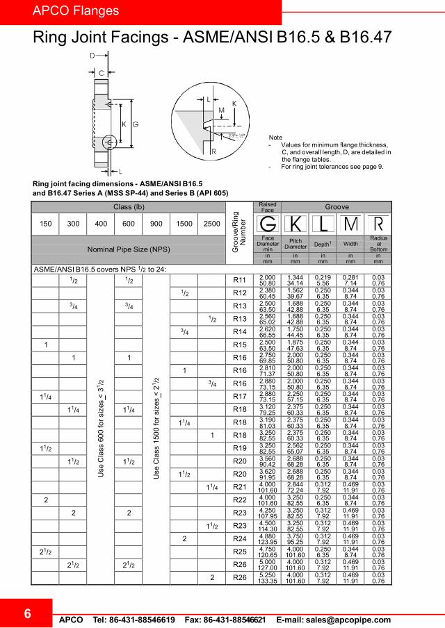
Ring Joint Facings - ASME/ANSI B16.5 & B16.47
6 APCO Tel: 86-431-88546619 Fax: 86-431-88546621 E-mail: [email protected]
Note- Values for minimum flange thickness,
C, and overall length, D, are detailed in the flange tables.
- For ring joint tolerances see page 9.
Ring joint facing dimensions - ASME/ANSI B16.5and B16.47 Series A (MSS SP-44) and Series B (API 605)
Class (lb)
G
roov
e/R
ing
Num
ber
RaisedFace Groove
150
300
400
600
900
1500
2500
Nominal Pipe Size (NPS)
Face Diameter
minPitch
Diameter
Depth1
Width
Radius at
Bottomin
mmin
mmin
mmin
mmin
mmASME/ANSI B16.5 covers NPS 1/2 to 24:
1/2
U
seC
lass
600
fors
izes
<31 /2
1/2
U
seC
lass
1500
for s
izes
<21 /2
R11 2.00050.80
1.34434.14
0.2195.56
0.2817.14
0.030.76
1/2 R12 2.38060.45
1.56239.67
0.2506.35
0.3448.74
0.030.76
3/4 3/4 R13 2.50063.50
1.68842.88
0.2506.35
0.3448.74
0.030.76
1/2 R13 2.56065.02
1.68842.88
0.2506.35
0.3448.74
0.030.76
3/4 R14 2.62066.55
1.75044.45
0.2506.35
0.3448.74
0.030.76
1 R15 2.50063.50
1.87547.63
0.2506.35
0.3448.74
0.030.76
1 1 R16 2.75069.85
2.00050.80
0.2506.35
0.3448.74
0.030.76
1 R16 2.81071.37
2.00050.80
0.2506.35
0.3448.74
0.030.76
3/4 R16 2.88073.15
2.00050.80
0.2506.35
0.3448.74
0.030.76
11/4 R17 2.88073.15
2.25057.15
0.2506.35
0.3448.74
0.030.76
11/4 11/4 R18 3.12079.25
2.37560.33
0.2506.35
0.3448.74
0.030.76
11/4 R18 3.19081.03
2.37560.33
0.2506.35
0.3448.74
0.030.76
1 R18 3.25082.55
2.37560.33
0.2506.35
0.3448.74
0.030.76
11/2 R19 3.25082.55
2.56265.07
0.2506.35
0.3448.74
0.030.76
11/2 11/2 R20 3.56090.42
2.68868.28
0.2506.35
0.3448.74
0.030.76
11/2 R20 3.62091.95
2.68868.28
0.2506.35
0.3448.74
0.030.76
11/4 R21 4.000101.60
2.84472.24
0.3127.92
0.46911.91
0.030.76
2 R22 4.000101.60
3.25082.55
0.2506.35
0.3448.74
0.030.76
2 2 R23 4.250107.95
3.25082.55
0.3127.92
0.46911.91
0.030.76
11/2 R23 4.500114.30
3.25082.55
0.3127.92
0.46911.91
0.030.76
2 R24 4.880123.95
3.75095.25
0.3127.92
0.46911.91
0.030.76
21/2 R25 4.750120.65
4.000101.60
0.2506.35
0.3448.74
0.030.76
21/2 21/2 R26 5.000127.00
4.000101.60
0.3127.92
0.46911.91
0.030.76
2 R26 5.250133.35
4.000101.60
0.3127.92
0.46911.91
0.030.76

APCO Flanges
Ring Joint Facings - ASME/ANSI B16.5 & B16.47Ring joint facing dimensions - ASME/ANSI B16.5and B16.47 Series A (MSS SP-44) and Series B (API 605) (Continued)
7APCO Tel: 86-431-88546619 Fax: 86-431-88546621 E-mail: [email protected]
Num
ber
Class (lb)
G
roov
e/R
ing
RaisedFace Groove
150 300 400 600 900 1500 2500
Nominal Pipe Size (NPS)
Face Diameter
minPitch
Diameter
Depth1
Width
Radius at
Bottomin
mmin
mmin
mmin
mmin
mm
U
seC
lass
600
fors
izes
<31 /
2 21/2 R27 5.380136.65
4.250107.95
0.3127.92
0.46911.91
0.030.76
21/2 R28 5.880149.35
4.375111.13
0.3759.53
0.53113.49
0.061.52
3 R29 5.250133.35
4.500114.30
0.2506.35
0.3448.74
0.030.76
-2 -2 R30 - 4.625117.48
0.3127.92
0.46911.91
0.030.76
32 32 R31 5.750146.05
4.875123.83
0.3127.92
0.46911.91
0.030.76
3 R31 6.120155.45
4.875123.83
0.3127.92
0.46911.91
0.030.76
3 R32 6.620168.15
5.000127.00
0.3759.53
0.53113.49
0.061.52
31/2 R33 6.060153.92
5.188131.78
0.2506.35
0.3448.74
0.030.76
31/2 31/2 R34 6.250158.75
5.188131.78
0.3127.92
0.46911.91
0.030.76
3 R35 6.620168.15
5.375136.53
0.3127.92
0.46911.91
0.030.76
4 R36 6.750171.45
5.875149.23
0.2506.35
0.3448.74
0.030.76
4 4 4 R37 6.880174.75
5.875149.23
0.3127.92
0.46911.91
0.030.76
4 R37 7.120180.85
5.875149.23
0.3127.92
0.46911.91
0.030.76
4 R38 8.000203.20
6.188157.18
0.43811.13
0.65616.66
0.061.52
4 R39 7.620193.55
6.375161.93
0.3127.92
0.46911.91
0.030.76
5 R40 7.620193.55
6.750171.45
0.2506.35
0.3448.74
0.030.76
5 5 5 R41 8.250209.55
7.125180.98
0.3127.92
0.46911.91
0.030.76
5 R41 8.500215.90
7.125180.98
0.3127.92
0.46911.91
0.030.76
5 R42 9.500241.30
7.500190.50
0.50012.70
0.78119.84
0.061.52
6 R43 8.620218.95
7.625193.68
0.2506.35
0.3448.74
0.030.76
5 R44 9.000228.60
7.625193.68
0.3127.92
0.46911.91
0.030.76
6 6 6 R45 9.500241.30
8.312211.12
0.3127.92
0.46911.91
0.030.76
6 R45 9.500241.30
8.312211.12
0.3127.92
0.46911.91
0.030.76
6 R46 9.750247.65
8.312211.12
0.3759.53
0.53113.49
0.061.52
6 R47 11.000279.40
9.000228.60
0.50012.70
0.78119.84
0.061.52
8 R48 10.750273.05
9.750247.65
0.2506.35
0.3448.74
0.030.76
8 8 8 R49 11.880301.75
10.625269.88
0.3127.92
0.46911.91
0.030.76
8 R49 12.120307.85
10.625269.88
0.3127.92
0.46911.91
0.030.76
8 R50 12.500317.50
10.625269.88
0.43811.13
0.65616.66
0.061.52
8 R51 13.380339.85
11.000279.40
0.56214.27
0.90623.01
0.061.52
10 R52 13.000330.20
12.000304.80
0.2506.35
0.3448.74
0.030.76
10 10 10 R53 14.000355.60
12.750323.85
0.3127.92
0.46911.91
0.030.76
10 R53 14.250361.95
12.750323.85
0.3127.92
0.46911.91
0.030.76
10 R54 14.620371.35
12.750323.85
0.43811.13
0.65616.66
0.061.52

APCO Flanges
Ring Joint Facings - ASME/ANSI B16.5 & B16.47
8 APCO Tel: 86-431-88546619 Fax: 86-431-88546621 E-mail: [email protected]
Ring joint facing dimensions - ASME/ANSI B16.5
Note- Values for minimum flange thickness,
C, and overall length, D, are detailed in the flange tables.
- For ring joint tolerancessee page 9.
and B16.47 Series A (MSS SP-44) and Series B (API 605) (Continued)
Class (lb)
G
roov
e/R
ing
Num
ber
RaisedFace Groove
150
300
400
600
900
1500
2500
Nominal Pipe Size (NPS)
Face Diameter
minPitch
Diameter Depth1
WidthRadius
at Bottom
in mm
in mm
in mm
in mm
in mm
10 R55 16.750425.45
13.500342.90
0.68817.48
1.18830.18
0.092.29
12 R56 16.000406.40
15.000381.00
0.2506.35
0.3448.74
0.030.76
12 12 12 R57 16.250412.75
15.000381.00
0.3127.92
0.46911.91
0.030.76
12 R57 16.500419.10
15.000381.00
0.3127.92
0.46911.91
0.030.76
12 R58 17.250438.15
15.000381.00
0.56214.27
0.90623.01
0.061.52
14 R59 16.750425.45
15.625396.88
0.2506.35
0.3448.74
0.030.76
12 R60 19.500495.30
16.000406.40
0.68817.48
1.31233.32
0.092.29
14 14 14 R61 18.000457.20
16.500419.10
0.3127.92
0.46911.91
0.030.76
14 R62 18.380466.85
16.500419.10
0.43811.13
0.65616.66
0.061.52
14 R63 19.250488.95
16.500419.10
0.62515.88
1.06226.97
0.092.29
16 R64 19.000482.60
17.875454.03
0.2506.35
0.3448.74
0.030.76
16 16 16 R65 20.000508.00
18.500469.90
0.3127.92
0.46911.91
0.030.76
16 R66 20.620523.75
18.500469.90
0.43811.13
0.65616.66
0.061.52
16 R67 21.500546.10
18.500469.90
0.68817.48
1.18830.18
0.092.29
18 R68 21.500546.10
20.375517.53
0.2506.35
0.3448.74
0.030.76
18 18 18 R69 22.620574.55
21.000533.40
0.3127.92
0.46911.91
0.030.76
18 R70 23.380593.85
21.000533.40
0.50012.70
0.78119.84
0.061.52
18 R71 24.120612.65
21.000533.40
0.68817.48
1.18830.18
0.092.29
20 R72 23.500596.90
22.000558.80
0.2506.35
0.3448.74
0.030.76
20 20 20 R73 25.000635.00
23.000584.20
0.3759.53
0.53113.49
0.061.52
20 R74 25.500647.70
23.000584.20
0.50012.70
0.78119.84
0.061.52
20 R75 26.500673.10
23.000584.20
0.68817.48
1.31233.32
0.092.29
24 R76 28.000711.20
26.500673.10
0.2506.35
0.3448.74
0.030.76
24 24 24 R77 29.500749.30
27.250692.15
0.43811.13
0.65616.66
0.061.52
24 R78 30.380771.65
27.250692.15
0.62515.88
1.06226.97
0.092.29

APCO Flanges
Ring Joint Facings - ASME/ANSI B16.5 & B16.47Ring joint facing dimensions - ASME/ANSI B16.5and B16.47 Series A (MSS SP-44) and Series B (API 605) (Continued)
9APCO Tel: 86-431-88546619 Fax: 86-431-88546621 E-mail: [email protected]
Num
ber
Class (lb)
G
roov
e/R
ing
RaisedFace Groove
150 300 400 600 900 1500 2500
Nominal Pipe Size (NPS)
Face Diameter
minPitch
Diameter
Depth1
Width
Radius at
Bottomin
mmin
mmin
mmin
mmin
mm
24 R79 31.250793.75
27.250692.15
0.81220.62
1.43836.53
0.092.29
MSS SP-44 only, covers NPS 22:
22 22 22 R81 27.000685.80
25.000635.00
0.43811.13
0.59415.09
0.061.52
ASME/ANSI B16.47 (MSS SP-44 & API 605) covers NPS 26 to 36. (There are no ring joint facings >NPS 36)
26 26 26 R93 31.880809.75
29.500749.30
0.50012.70
0.78119.84
0.061.52
28 28 28 R94 33.880860.55
31.500800.10
0.50012.70
0.78119.84
0.061.52
30 30 30 R95 36.120917.45
33.750857.25
0.50012.70
0.78119.84
0.061.52
32 32 32 R96 38.750984.25
36.000914.40
0.56214.27
0.90623.01
0.061.52
34 34 34 R97 40.7501035.1
38.000965.20
0.56214.27
0.90623.01
0.061.52
36 36 36 R98 43.0001092.2
40.2501022.4
0.56214.27
0.90623.01
0.061.52
26 R100 32.750831.85
29.500749.30
0.68817.48
1.18830.18
0.092.29
28 R101 35.000889.00
31.500800.10
0.68817.48
1.31233.32
0.092.29
30 R102 37.250946.15
33.750857.25
0.68817.48
1.31233.32
0.092.29
32 R103 39.5001003.3
36.000914.40
0.68817.48
1.31233.32
0.092.29
34 R104 42.0001066.8
38.000965.20
0.81220.62
1.43836.53
0.092.29
36 R105 44.2501124.0
40.2501022.4
0.81220.62
1.43836.53
0.092.29
Notes- Ring joint gasket dimensions conform to ASME B16.20 (not covered in this summary).- Use Class 600 lb in sizes NPS 1/2 to NPS 31/2 for Class 400 lb.- Use Class 1500 lb in sizes NPS 1/2 to NPS 21/2 for Class 900 lb.- Tolerances are as shown in the table below.1 The height of the raised portion is equal to the depth of groove dimension L, but is not subject to the tolerances for L.2 Ring joints with lapped flanges in Classes 300 lb and 600 lb use R30 instead of R31.
Ring joint facing tolerances (ASME/ANSI B16.5 and B16.47)
Dimension Range Tolerancein mm
L (depth) All +0.016, -0 +0.406, -0M (width) All ±0.008 ±0.203
K (pitch diameter) All ±0.005 ±0.127
R (radius at bottom)R < 0.06 in +0.03, -0 +0.762, -0R > 0.06 in ±0.03 ±0.762> NPS 26 maximum quoted
D (overall length) forflanges with ring joint
< NPS 10 ±0.06 ±1.52> NPS 12 ±0.12 ±3.05
APCO Flanges
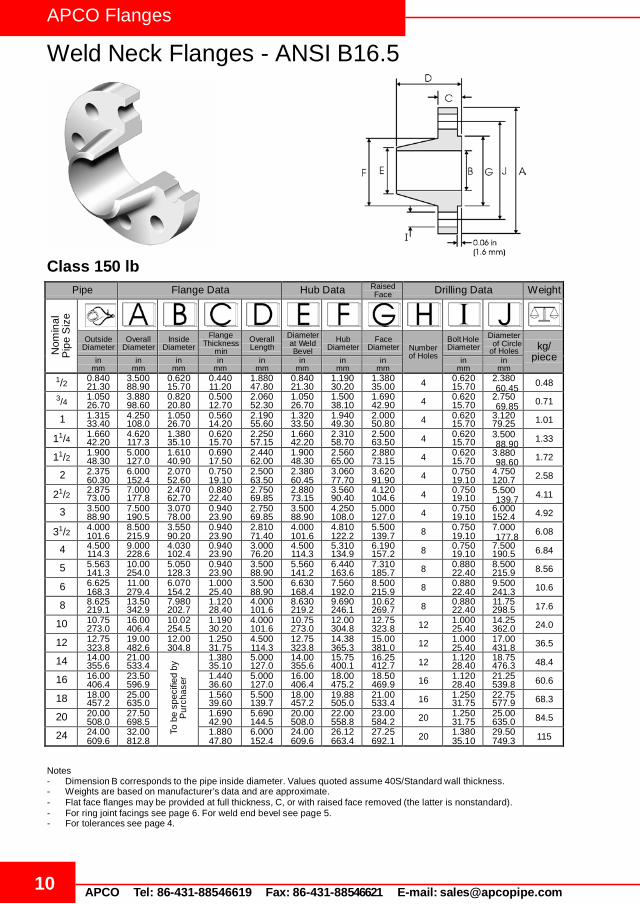
Weld Neck Flanges - ANSI B16.5
10 APCO Tel: 86-431-88546619 Fax: 86-431-88546621 E-mail: [email protected]
Pipe Flange Data Hub Data Raised Face Drilling Data Weight
Nom
inal
P
ipe
Siz
e
Outside Diameter
Overall Diameter
Inside Diameter
Flange Thickness
min Overall Length
Diameter at Weld Bevel
Hub Diameter
Face Diameter
Number of Holes
Bolt Hole Diameter
Diameter
of Holes
kg/
piece in mm
in mm
in mm
in mm
in mm
in mm
in mm
in mm
in mm
in mm
1/2 0.840 21.30
3.500 88.90
0.620 15.70
0.440 11.20
1.880 47.80
0.840 21.30
1.190 30.20
1.380 35.00 4 0.620
15.70 2.380 0.48
3/4 1.050 26.70
3.880 98.60
0.820 20.80
0.500 12.70
2.060 52.30
1.050 26.70
1.500 38.10
1.690 42.90 4 0.620
15.70 2.750 0.71
1 1.315 33.40
4.250 108.0
1.050 26.70
0.560 14.20
2.190 55.60
1.320 33.50
1.940 49.30
2.000 50.80 4 0.620
15.70 3.120 79.25 1.01
11/4 1.660 42.20
4.620 117.3
1.380 35.10
0.620 15.70
2.250 57.15
1.660 42.20
2.310 58.70
2.500 63.50 4 0.620
15.70 3.500 1.33
11/2 1.900 48.30
5.000 127.0
1.610 40.90
0.690 17.50
2.440 62.00
1.900 48.30
2.560 65.00
2.880 73.15 4 0.620
15.70 3.880 1.72
2 2.375 60.30
6.000 152.4
2.070 52.60
0.750 19.10
2.500 63.50
2.380 60.45
3.060 77.70
3.620 91.90 4 0.750
19.10 4.750 120.7 2.58
21/2 2.875 73.00
7.000 177.8
2.470 62.70
0.880 22.40
2.750 69.85
2.880 73.15
3.560 90.40
4.120 104.6 4 0.750
19.10 5.500 4.11
3 3.500 88.90
7.500 190.5
3.070 78.00
0.940 23.90
2.750 69.85
3.500 88.90
4.250 108.0
5.000 127.0 4 0.750
19.10 6.000 152.4 4.92
31/2 4.000 101.6
8.500 215.9
3.550 90.20
0.940 23.90
2.810 71.40
4.000 101.6
4.810 122.2
5.500 139.7 8 0.750
19.10 7.000 6.08
4 4.500 114.3
9.000 228.6
4.030 102.4
0.940 23.90
3.000 76.20
4.500 114.3
5.310 134.9
6.190 157.2 8 0.750
19.10 7.500 190.5 6.84
5 5.563 141.3
10.00 254.0
5.050 128.3
0.940 23.90
3.500 88.90
5.560 141.2
6.440 163.6
7.310 185.7 8 0.880
22.40 8.500 215.9 8.56
6 6.625 168.3
11.00 279.4
6.070 154.2
1.000 25.40
3.500 88.90
6.630 168.4
7.560 192.0
8.500 215.9 8 0.880
22.40 9.500 241.3 10.6
8 8.625 219.1
13.50 342.9
7.980 202.7
1.120 28.40
4.000 101.6
8.630 219.2
9.690 246.1
10.62 269.7 8 0.880
22.40 11.75 298.5 17.6
10 10.75 273.0
16.00 406.4
10.02 254.5
1.190 30.20
4.000 101.6
10.75 273.0
12.00 304.8
12.75 323.8 12 1.000
25.40 14.25 362.0 24.0
12 12.75 323.8
19.00 482.6
12.00 304.8
1.250 31.75
4.500 114.3
12.75 323.8
14.38 365.3
15.00 381.0 12 1.000
25.40 17.00 431.8 36.5
14 14.00 355.6
21.00 533.4
To
be
spec
ified
by
Purc
hase
r
1.380 35.10
5.000 127.0
14.00 355.6
15.75 400.1
16.25 412.7 12 1.120
28.40 18.75 476.3 48.4
16 16.00 406.4
23.50 596.9
1.440 36.60
5.000 127.0
16.00 406.4
18.00 475.2
18.50 469.9 16 1.120
28.40 21.25 539.8 60.6
18 18.00 457.2
25.00 635.0
1.560 39.60
5.500 139.7
18.00 457.2
19.88 505.0
21.00 533.4 16 1.250
31.75 22.75 577.9 68.3
20 20.00 508.0
27.50 698.5
1.690 42.90
5.690 144.5
20.00 508.0
22.00 558.8
23.00 584.2 20 1.250
31.75 25.00 635.0 84.5
24 24.00 609.6
32.00 812.8
1.880 47.80
6.000 152.4
24.00 609.6
26.12 663.4
27.25 692.1 20 1.380
35.10 29.50 749.3 115
Class 150 lb
of Circle
60.45
69.85
88.90
98.60
139.7
177.8
Notes - Dimension B corresponds to the pipe inside diameter. Values quoted assume 40S/Standard wall thickness. - Weights are based on manufacturer’s data and are approximate. - Flat face flanges may be provided at full thickness, C, or with raised face removed (the latter is nonstandard). - For ring joint facings see page 6. For weld end bevel see page 5. - For tolerances see page 4.

APCO Flanges
Weld Neck Flanges - ANSI B16.5
11 APCO Tel: 86-431-88546619 Fax: 86-431-88546621 E-mail: [email protected]
Pipe Flange Data Hub Data Raised Face Drilling Data Weight
Nom
inal
P
ipe
Siz
e
Outside Diameter
Overall Diameter
Inside Diameter
Flange Thickness
min Overall Length
Diameter at Weld Bevel
Hub Diameter
Face Diameter
Number of Holes
Bolt Hole Diameter
Diameter
of Holes
kg/
piece in mm
in mm
in mm
in mm
in mm
in mm
in mm
in mm
in mm
in mm
1/2 0.840 21.30
3.750 95.20
0.620 15.70
0.560 14.20
2.060 52.30
0.840 21.30
1.500 38.10
1.380 35.00 4 0.620
15.70 2.620 0.75
3/4 1.050 26.70
4.620 117.3
0.820 20.80
0.620 15.70
2.250 57.15
1.050 26.70
1.880 47.70
1.690 42.90 4 0.750
19.00 3.250 1.26
1 1.315 33.40
4.880 123.9
1.050 26.70
0.690 17.50
2.440 62.00
1.320 33.50
2.120 53.80
2.000 50.80 4 0.750
19.00 3.500 88.90 1.52
11/4 1.660 42.20
5.250 133.3
1.380 35.10
0.750 19.00
2.560 65.00
1.660 42.20
2.500 63.50
2.500 63.50 4 0.750
19.00 3.880 2.03
11/2 1.900 48.30
6.120 155.4
1.610 40.90
0.810 20.60
2.690 68.30
1.900 48.30
2.750 69.85
2.880 73.15 4 0.880
22.30 4.500 2.89
2 2.375 60.30
6.500 165.1
2.070 52.60
0.880 22.30
2.750 69.85
2.380 60.45
3.310 84.00
3.620 91.90 8 0.750
19.00 5.000 127.0 3.40
21/2 2.875 73.00
7.500 190.5
2.470 62.70
1.000 25.40
3.000 76.20
2.880 73.15
3.940 100.0
4.120 104.6 8 0.880
22.30 5.880 5.17
3 3.500 88.90
8.250 209.5
3.070 78.00
1.120 28.40
3.120 79.25
3.500 88.90
4.620 117.3
5.000 127.0 8 0.880
22.30 6.620 168.1 6.93
31/2 4.000 101.6
9.000 228.6
3.550 90.20
1.190 30.20
3.190 81.00
4.000 101.6
5.250 133.3
5.500 139.7 8 0.880
22.30 7.250 8.67
4 4.500 114.3
10.00 254.0
4.030 102.4
1.250 31.70
3.380 85.80
4.500 114.3
5.750 146.0
6.190 157.2 8 0.880
22.30 7.880 200.1 11.2
5 5.563 141.3
11.00 279.4
5.050 128.3
1.380 35.00
3.880 98.50
5.560 141.2
7.000 177.8
7.310 185.7 8 0.880
22.30 9.250 234.9 15.1
6 6.625 168.3
12.50 317.5
6.070 154.2
1.440 36.50
3.880 98.50
6.630 168.4
8.120 206.2
8.500 215.9 12 0.880
22.30 10.62 269.7 19.1
8 8.625 219.1
15.00 381.0
7.980 202.7
1.620 41.10
4.380 111.2
8.630 219.2
10.25 260.3
10.62 269.7 12 1.000
25.40 13.00 330.2 29.9
10 10.75 273.0
17.50 444.5
10.02 254.5
1.880 47.70
4.620 117.3
10.75 273.0
12.62 320.5
12.75 323.8 16 1.120
28.40 15.25 387.3 42.7
12 12.75 323.8
20.50 520.7
12.00 304.8
2.000 50.80
5.120 130.0
12.75 323.8
14.75 374.6
15.00 381.0 16 1.250
31.70 17.75 450.8 61.8
14 14.00 355.6
23.00 584.2
To
be
spec
ified
by
2.120 53.80
5.620 142.7
14.00 355.6
16.75 425.4
16.25 412.7 20 1.250
31.70 20.25 514.3 85.8
16 16.00 406.4
25.50 647.7
2.250 57.15
5.750 146.0
16.00 406.4
19.00 482.6
18.50 469.9 20 1.380
35.00 22.50 571.5 106
18 18.00 457.2
28.00 711.2
2.380 60.45
6.250 158.7
18.00 457.2
21.00 533.4
21.00 533.4 24 1.380
35.00 24.75 628.6 131
20 20.00 508.0
30.50 774.7
2.500 63.50
6.380 162.0
20.00 508.0
23.12 587.2
23.00 584.2 24 1.380
35.00 27.00 685.8 158
24 24.00 609.6
36.00 914.4
2.750 69.85
6.620 168.1
24.00 609.6
27.62 701.5
27.25 692.1 24 1.620
41.10 32.00 812.8 230
Purc
hase
r
Class 300 lb
of Circle
66.55
82.50
98.50
114.3
149.3
184.1
Notes - Dimension B corresponds to the pipe inside diameter. Values quoted assume 40S/Standard wall thickness. - Weights are based on manufacturer’s data and are approximate. - Flat face flanges may be provided at full thickness, C, or with raised face removed (the latter is nonstandard). - For ring joint facings see page 6. For weld end bevel see page 5. - For tolerances see page 4.

APCO Flanges
Weld Neck Flanges - ANSI B16.5
12 APCO Tel: 86-431-88546619 Fax: 86-431-88546621 E-mail: [email protected]
Pipe Flange Data Hub Data Raised Face Drilling Data Weight
Nom
inal
P
ipe
Siz
e
Outside Diameter
Overall Diameter
Inside Diameter
Flange Thickness
min Overall Length
Diameter at Weld Bevel
Hub Diameter
Face Diameter
Number of Holes
Bolt Hole Diameter
Diameter
of Holes
kg/
piece in mm
in mm
in mm
in mm
in mm
in mm
in mm
in mm
in mm
in mm
1/2 0.840 21.30
3.750 95.30
To
be
spec
ified
by
0.560 14.20
2.060 52.30
0.840 21.30
1.500 38.10
1.380 35.00 4 0.620
15.70 2.620 0.87
3/4 1.050 26.70
4.620 117.3
0.620 15.70
2.250 57.15
1.050 26.70
1.880 47.80
1.690 42.90 4 0.750
19.10 3.250 1.45
1 1.315 33.40
4.880 124.0
0.690 17.50
2.440 62.00
1.320 33.50
2.120 53.80
2.000 50.80 4 0.750
19.10 3.500 88.90 1.76
11/4 1.660 42.20
5.250 133.4
0.810 20.60
2.620 66.55
1.660 42.20
2.500 63.50
2.500 63.50 4 0.750
19.10 3.880 2.49
11/2 1.900 48.30
6.120 155.4
0.880 22.40
2.750 69.85
1.900 48.30
2.750 69.85
2.880 73.15 4 0.880
22.40 4.500 3.49
2 2.375 60.30
6.500 165.1
1.000 25.40
2.880 73.15
2.380 60.45
3.310 84.10
3.620 91.90 8 0.750
19.10 5.000 127.0 4.36
21/2 2.875 73.00
7.500 190.5
1.120 28.40
3.120 79.25
2.880 73.15
3.940 100.1
4.120 104.6 8 0.880
22.40 5.880 6.43
3 3.500 88.90
8.250 209.6
1.250 31.75
3.250 82.60
3.500 88.90
4.620 117.3
5.000 127.0 8 0.880
22.40 6.620 168.1 8.53
31/2 4.000 101.6
9.000 228.6
1.380 35.10
3.380 85.90
4.000 101.6
5.250 133.4
5.500 139.7 8 1.000
25.40 7.250 10.7
4 4.500 114.3
10.00 254.0
1.380 35.10
3.500 88.90
4.500 114.3
5.750 146.1
6.190 157.2 8 1.000
25.40 7.880 200.2 12.8
5 5.563 141.3
11.00 279.4
1.500 38.10
4.000 101.6
5.560 141.2
7.000 177.8
7.310 185.7 8 1.000
25.40 9.250 235.0 16.9
6 6.625 168.3
12.50 317.5
1.620 41.10
4.060 103.1
6.630 168.4
8.120 206.2
8.500 215.9 12 1.000
25.40 10.62 269.7 22.0
8 8.625 219.1
15.00 381.0
1.880 47.80
4.620 117.3
8.630 219.2
10.25 260.4
10.62 269.7 12 1.120
28.40 13.00 330.2 34.7
10 10.75 273.0
17.50 444.5
2.120 53.80
4.880 124.0
10.75 273.0
12.62 320.5
12.75 323.8 16 1.250
31.75 15.25 387.4 48.5
12 12.75 323.8
20.50 520.7
2.250 57.15
5.380 136.7
12.75 323.8
14.75 374.7
15.00 381.0 16 1.380
35.10 17.75 450.9 69.6
14 14.00 355.6
23.00 584.2
2.380 60.45
5.880 149.4
14.00 355.6
16.75 425.5
16.25 412.7 20 1.380
35.10 20.25 514.4 95.5
16 16.00 406.4
25.50 647.7
2.500 63.50
6.000 152.4
16.00 406.4
19.00 482.6
18.50 469.9 20 1.500
38.10 22.50 571.5 118
18 18.00 457.2
28.00 711.2
2.620 66.55
6.500 165.1
18.00 457.2
21.00 533.4
21.00 533.4 24 1.500
38.10 24.75 628.7 145
20 20.00 508.0
30.50 774.7
2.750 69.85
6.620 168.1
20.00 508.0
23.12 587.2
23.00 584.2 24 1.620
41.10 27.00 685.8 173
24 24.00 609.6
36.00 914.4
3.000 76.20
6.880 174.8
24.00 609.6
27.62 701.5
27.25 692.1 24 1.880
47.80 32.00 812.8 249
Purc
hase
r
Class 400 lb
of Circle
66.55
82.60
98.60
114.3
149.4
184.2
Notes - Dimension B corresponds to the pipe inside diameter. Values quoted assume 40S/Standard wall thickness. - Weights are based on manufacturer’s data and are approximate. - For ring joint facings see page 6. For weld end bevel see page 5. - For tolerances see page 4.

APCO Flanges
Weld Neck Flanges - ANSI B16.5
13 APCO Tel: 86-431-88546619 Fax: 86-431-88546621 E-mail: [email protected]
Pipe Flange Data Hub Data Raised Face Drilling Data Weight
Nom
inal
P
ipe
Siz
e
Outside Diameter
Overall Diameter
Inside Diameter
Flange Thickness
min Overall Length
Diameter at Weld Bevel
Hub Diameter
Face Diameter
Number of Holes
Bolt Hole Diameter
Diameter
of Holes
kg/
piece in mm
in mm
in mm
in mm
in mm
in mm
in mm
in mm
in mm
in mm
1/2 0.840 21.30
3.750 95.30
To
be
spec
ified
by
0.560 14.20
2.060 52.30
0.840 21.30
1.500 38.10
1.380 35.00 4 0.620
15.70 2.620 0.87
3/4 1.050 26.70
4.620 117.3
0.620 15.70
2.250 57.15
1.050 26.70
1.880 47.80
1.690 42.90 4 0.750
19.10 3.250 1.45
1 1.315 33.40
4.880 124.0
0.690 17.50
2.440 62.00
1.320 33.50
2.120 53.80
2.000 50.80 4 0.750
19.10 3.500 88.90 1.76
11/4 1.660 42.20
5.250 133.4
0.810 20.60
2.620 66.55
1.660 42.20
2.500 63.50
2.500 63.50 4 0.750
19.10 3.880 2.49
11/2 1.900 48.30
6.120 155.4
0.880 22.40
2.750 69.85
1.900 48.30
2.750 69.85
2.880 73.15 4 0.880
22.40 4.500 3.49
2 2.375 60.30
6.500 165.1
1.000 25.40
2.880 73.15
2.380 60.45
3.310 84.10
3.620 91.90 8 0.750
19.10 5.000 127.0 4.36
21/2 2.875 73.00
7.500 190.5
1.120 28.40
3.120 79.25
2.880 73.15
3.940 100.1
4.120 104.6 8 0.880
22.40 5.880 6.43
3 3.500 88.90
8.250 209.6
1.250 31.75
3.250 82.60
3.500 88.90
4.620 117.3
5.000 127.0 8 0.880
22.40 6.620 168.1 8.53
31/2 4.000 101.6
9.000 228.6
1.380 35.10
3.380 85.90
4.000 101.6
5.250 133.4
5.500 139.7 8 1.000
25.40 7.250 10.7
4 4.500 114.3
10.75 273.1
1.500 38.10
4.000 101.6
4.500 114.3
6.000 152.4
6.190 157.2 8 1.000
25.40 8.500 215.9 17.4
5 5.563 141.3
13.00 330.2
1.750 44.50
4.500 114.3
5.560 141.2
7.440 189.0
7.310 185.7 8 1.120
28.40 10.50 266.7 29.2
6 6.625 168.3
14.00 355.6
1.880 47.80
4.620 117.3
6.630 168.4
8.750 222.3
8.500 215.9 12 1.120
28.40 11.50 292.1 34.9
8 8.625 219.1
16.50 419.1
2.190 55.60
5.250 133.4
8.630 219.2
10.75 273.1
10.62 269.7 12 1.250
31.75 13.75 349.3 53.9
10 10.75 273.0
20.00 508.0
2.500 63.50
6.000 152.4
10.75 273.0
13.50 342.9
12.75 323.8 16 1.380
35.10 17.00 431.8 86.5
12 12.75 323.8
22.00 558.8
2.620 66.55
6.120 155.4
12.75 323.8
15.75 400.1
15.00 381.0 20 1.380
35.10 19.25 489.0 103
14 14.00 355.6
23.75 603.3
2.750 69.85
6.500 165.1
14.00 355.6
17.00 431.8
16.25 412.7 20 1.500
38.10 20.75 527.1 122
16 16.00 406.4
27.00 685.8
3.000 76.20
7.000 177.8
16.00 406.4
19.50 495.3
18.50 469.9 20 1.620
41.10 23.75 603.3 170
18 18.00 457.2
29.25 743.0
3.250 82.60
7.250 184.2
18.00 457.2
21.50 546.1
21.00 533.4 20 1.750
44.50 25.75 654.1 204
20 20.00 508.0
32.00 812.8
3.500 88.90
7.500 190.5
20.00 508.0
24.00 609.6
23.00 584.2 24 1.750
44.50 28.50 723.9 254
24 24.00 609.6
37.00 939.8
4.000 101.6
8.000 203.2
24.00 609.6
28.25 717.6
27.25 692.1 24 2.000
50.80 33.00 838.2 358
Purc
hase
r
Class 600 lb
of Circle
66.55
82.60
98.60
114.3
149.4
184.2
Notes - Dimension B corresponds to the pipe inside diameter. Values quoted assume 40S/Standard wall thickness. - Weights are based on manufacturer’s data and are approximate. - For ring joint facings see page 6. For weld end bevel see page 5. - For tolerances see page 4.

APCO Flanges
Weld Neck Flanges - ANSI B16.5
14 APCO Tel: 86-431-88546619 Fax: 86-431-88546621 E-mail: [email protected]
Pipe Flange Data Hub Data Raised Face Drilling Data Weight
Nom
inal
P
ipe
Siz
e
Outside Diameter
Overall Diameter
Inside Diameter
Flange Thickness
min Overall Length
Diameter at Weld Bevel
Hub Diameter
Face Diameter
Number of Holes
Bolt Hole Diameter
Diameter
of Holes
kg/
piece in mm
in mm
in mm
in mm
in mm
in mm
in mm
in mm
in mm
in mm
1/2 0.840 21.30
4.750 120.6
To
be
spec
ified
by
0.880 22.30
2.380 60.45
0.840 21.30
1.500 38.10
1.380 35.00 4 0.880
22.30 3.250 1.87
3/4 1.050 26.70
5.120 130.0
1.000 25.40
2.750 69.85
1.050 26.70
1.750 44.00
1.690 42.90 4 0.880
22.30 3.500 2.56
1 1.315 33.40
5.880 149.3
1.120 28.40
2.880 73.15
1.320 33.50
2.060 52.30
2.000 50.80 4 1.000
25.40 4.000 101.6 3.74
11/4 1.660 42.20
6.250 158.7
1.120 28.40
2.880 73.15
1.660 42.20
2.500 63.50
2.500 63.50 4 1.000
25.40 4.380 4.33
11/2 1.900 48.30
7.000 177.8
1.250 31.70
3.250 82.50
1.900 48.30
2.750 69.85
2.880 73.15 4 1.120
28.40 4.880 5.94
2 2.375 60.30
8.500 215.9
1.500 38.10
4.000 101.6
2.380 60.45
4.120 104.6
3.620 91.90 8 1.000
25.40 6.500 165.1 10.8
21/2 2.875 73.00
9.620 244.3
1.620 41.10
4.120 104.6
2.880 73.15
4.880 123.9
4.120 104.6 8 1.120
28.40 7.500 15.0
3 3.500 88.90
9.500 241.3
1.500 38.10
4.000 101.6
3.500 88.90
5.000 127.0
5.000 127.0 8 1.000
25.40 7.500 190.5 13.7
4 4.500 114.3
11.50 292.1
1.750 44.40
4.500 114.3
4.500 114.3
6.250 158.7
6.190 157.2 8 1.250
31.70 9.250 234.9 22.5
5 5.563 141.3
13.75 349.2
2.000 50.80
5.000 127.0
5.560 141.2
7.500 190.5
7.310 185.7 8 1.380
35.00 11.00 279.4 37.4
6 6.625 168.3
15.00 381.0
2.190 55.60
5.500 139.7
6.630 168.4
9.250 234.9
8.500 215.9 12 1.250
31.70 12.50 317.5 47.7
8 8.625 219.1
18.50 469.9
2.500 63.50
6.380 162.0
8.630 219.2
11.75 298.4
10.62 269.7 12 1.500
38.10 15.50 393.7 81.3
10 10.75 273.0
21.50 546.1
2.750 69.85
7.250 184.1
10.75 273.0
14.50 368.3
12.75 323.8 16 1.500
38.10 18.50 469.9 119
12 12.75 323.8
24.00 609.6
3.120 79.25
7.880 200.1
12.75 323.8
16.50 419.1
15.00 381.0 20 1.500
38.10 21.00 533.4 157
14 14.00 355.6
25.25 641.3
3.380 85.80
8.380 212.8
14.00 355.6
17.75 450.8
16.25 412.7 20 1.620
41.10 22.00 558.8 180
16 16.00 406.4
27.75 704.8
3.500 88.90
8.500 215.9
16.00 406.4
20.00 508.0
18.50 469.9 20 1.750
44.40 24.25 615.9 217
18 18.00 457.2
31.00 787.4
4.000 101.6
9.000 228.6
18.00 457.2
22.25 565.1
21.00 533.4 20 2.000
50.80 27.00 685.8 292
20 20.00 508.0
33.75 857.2
4.250 107.9
9.750 247.6
20.00 508.0
24.50 622.3
23.00 584.2 20 2.120
53.80 29.50 749.3 362
24 24.00 609.6
41.00 1041.4
5.500 139.7
11.50 292.1
24.00 609.6
29.50 749.3
27.25 692.1 20 2.620
66.55 35.50 901.7 665
Purc
hase
r
Class 900 lb
of Circle
82.50
88.90
111.2
123.9
190.5
Notes - Dimension B corresponds to the pipe inside diameter. Values quoted assume 40S/Standard wall thickness. - Weights are based on manufacturer’s data and are approximate. - For ring joint facings see page 6. For weld end bevel see page 5. - For tolerances see page 4.

APCO Flanges
Weld Neck Flanges - ANSI B16.5
15 APCO Tel: 86-431-88546619 Fax: 86-431-88546621 E-mail: [email protected]
Pipe Flange Data Hub Data Raised Face Drilling Data Weight
Nom
inal
P
ipe
Siz
e
Outside Diameter
Overall Diameter
Inside Diameter
Flange Thickness
min Overall Length
Diameter at Weld Bevel
Hub Diameter
Face Diameter
Number of Holes
Bolt Hole Diameter
Diameter
of Holes
kg/
piece in mm
in mm
in mm
in mm
in mm
in mm
in mm
in mm
in mm
in mm
1/2 0.840 21.30
4.750 120.6
To
be
spec
ified
by
0.880 22.30
2.380 60.45
0.840 21.30
1.500 38.10
1.380 35.00 4 0.880
22.30 3.250 1.87
3/4 1.050 26.70
5.120 130.0
1.000 25.40
2.750 69.85
1.050 26.70
1.750 44.00
1.690 42.90 4 0.880
22.30 3.500 2.56
1 1.315 33.40
5.880 149.3
1.120 28.40
2.880 73.15
1.320 33.50
2.060 52.30
2.000 50.80 4 1.000
25.40 4.000 101.6 3.74
11/4 1.660 42.20
6.250 158.7
1.120 28.40
2.880 73.15
1.660 42.20
2.500 63.50
2.500 63.50 4 1.000
25.40 4.380 4.33
11/2 1.900 48.30
7.000 177.8
1.250 31.70
3.250 82.50
1.900 48.30
2.750 69.85
2.880 73.15 4 1.120
28.40 4.880 5.94
2 2.375 60.30
8.500 215.9
1.500 38.10
4.000 101.6
2.380 60.45
4.120 104.6
3.620 91.90 8 1.000
25.40 6.500 165.1 10.8
21/2 2.875 73.00
9.620 244.3
1.620 41.10
4.120 104.6
2.880 73.15
4.880 123.9
4.120 104.6 8 1.120
28.40 7.500 15.0
3 3.500 88.90
10.50 266.7
1.880 47.70
4.620 177.3
3.500 88.90
5.250 133.3
5.000 127.0 8 1.250
31.70 8.000 203.2 19.9
4 4.500 114.3
12.25 311.1
2.120 53.80
4.880 123.9
4.500 114.3
6.380 162.0
6.190 157.2 8 1.380
35.00 9.500 241.3 29.9
5 5.563 141.3
14.75 374.6
2.880 73.15
6.120 155.4
5.560 141.2
7.750 196.8
7.310 185.7 8 1.620
41.10 11.50 292.1 55.4
6 6.625 168.3
15.50 393.7
3.250 82.50
6.750 171.4
6.630 168.4
9.000 228.6
8.500 215.9 12 1.500
38.10 12.50 317.5 68.4
8 8.625 219.1
19.00 482.6
3.620 91.90
8.380 212.8
8.630 219.2
11.50 292.1
10.62 269.7 12 1.750
44.40 15.50 393.7 117
10 10.75 273.0
23.00 584.2
4.250 107.9
10.00 254.0
10.75 273.0
14.50 368.3
12.75 323.8 12 2.000
50.80 19.00 482.6 194
12 12.75 323.8
26.50 673.1
4.880 123.9
11.12 282.4
12.75 323.8
17.75 450.8
15.00 381.0 16 2.120
53.80 22.50 571.5 288
14 14.00 355.6
29.50 749.3
5.250 133.3
11.75 298.4
14.00 355.6
19.50 495.3
16.25 412.7 16 2.380
60.45 25.00 635.0 380
16 16.00 406.4
32.50 825.5
5.750 146.0
12.25 311.1
16.00 406.4
21.75 552.4
18.50 469.9 16 2.620
66.55 27.75 704.8 485
18 18.00 457.2
36.00 914.4
6.380 162.0
12.88 327.1
18.00 457.2
23.50 596.9
21.00 533.4 16 2.880
73.15 30.50 774.7 644
20 20.00 508.0
38.75 984.2
7.000 177.8
14.00 355.6
20.00 508.0
25.25 641.3
23.00 584.2 16 3.120
79.25 32.75 831.8 775
24 24.00 609.6
46.00 1168.4
8.000 203.2
16.00 406.4
24.00 609.6
30.00 762.0
27.25 692.1 16 3.620
91.90 39.00 990.6 1232
Purc
hase
r
Class 1500 lb
of Circle
82.50
88.90
111.2
123.9
190.5
Notes - Dimension B corresponds to the pipe inside diameter. Values quoted assume 40S/Standard wall thickness. - Weights are based on manufacturer’s data and are approximate. - For ring joint facings see page 6. For weld end bevel see page 5. - For tolerances see page 4.

APCO Flanges
Weld Neck Flanges - ANSI B16.5
16 APCO Tel: 86-431-88546619 Fax: 86-431-88546621 E-mail: [email protected]
Pipe Flange Data Hub Data Raised Face Drilling Data Weight
Nom
inal
Outside Diameter
Overall Diameter
Inside Diameter
Flange Thickness
min Overall Length
Diameter at Weld Bevel
Hub Diameter
Face Diameter
Number of Holes
Bolt Hole Diameter
Diameter
of Holes
kg/
piece in mm
in mm
in mm
in mm
in mm
in mm
in mm
in mm
in mm
in mm
1/2 0.840 21.30
5.250 133.4
To
be
spec
ified
by
Purc
hase
r
1.190 30.20
2.880 73.15
0.840 21.30
1.690 42.90
1.380 35.00 4 0.880
22.40 3.500 3.12
3/4 1.050 26.70
5.500 139.7
1.250 31.75
3.120 79.25
1.050 26.70
2.000 50.80
1.690 42.90 4 0.880
22.40 3.750 3.70
1 1.315 33.40
6.250 158.8
1.380 35.10
3.500 88.90
1.320 33.50
2.250 57.15
2.000 50.80 4 1.000
25.40 4.250 108.0 5.24
11/4 1.660 42.20
7.250 184.2
1.500 38.10
3.750 95.30
1.660 42.20
2.880 73.15
2.500 63.50 4 1.120
28.40 5.120 7.74
11/2 1.900 48.30
8.000 203.2
1.750 44.50
4.380 111.3
1.900 48.30
3.120 79.25
2.880 73.15 4 1.250
31.75 5.750 10.9
2 2.375 60.30
9.250 235.0
2.000 50.80
5.000 127.0
2.380 60.45
3.750 95.30
3.620 91.90 8 1.120
28.40 6.750 171.5 16.2
21/2 2.875 73.00
10.50 266.7
2.250 57.15
5.620 142.7
2.880 73.15
4.500 114.3
4.120 104.6 8 1.250
31.75 7.750 23.7
3 3.500 88.90
12.00 304.8
2.620 66.55
6.620 168.1
3.500 88.90
5.250 133.4
5.000 127.0 8 1.380
35.10 9.000 228.6 36.2
4 4.500 114.3
14.00 355.6
3.000 76.20
7.500 190.5
4.500 114.3
6.500 165.1
6.190 157.2 8 1.620
41.10 10.75 273.1 55.3
5 5.563 141.3
16.50 419.1
3.620 91.90
9.000 228.6
5.560 141.2
8.000 203.2
7.310 185.7 8 1.880
47.80 12.75 323.9 92.5
6 6.625 168.3
19.00 482.6
4.250 108.0
10.75 273.1
6.630 168.4
9.250 235.0
8.500 215.9 8 2.120
53.80 14.50 368.3 143
8 8.625 219.1
21.75 552.5
5.000 127.0
12.50 317.5
8.630 219.2
12.00 304.8
10.62 269.7 12 2.120
53.80 17.25 438.2 215
10 10.75 273.0
26.50 673.1
6.500 165.1
16.50 419.1
10.75 273.0
14.75 374.7
12.75 323.8 12 2.620
66.55 21.25 539.8 406
12 12.75 323.8
30.00 762.0
7.250 184.2
18.25 463.6
12.75 323.8
17.38 441.5
15.00 381.0 12 2.880
73.15 24.38 619.3 572
Pip
e S
ize
Class 2500 lb
of Circle
88.90
95.30
130.0
146.1
196.9
Notes - Dimension B corresponds to the pipe inside diameter. Values quoted assume 40S/Standard wall thickness. - Weights are based on manufacturer’s data and are approximate. - For ring joint facings see page 6. For weld end bevel see page 5. - For tolerances see page 4.

17 APCO Tel: 86-431-88546619 Fax: 86-431-88546621 E-mail: [email protected]
APCO Flanges
Slip On Flanges - ANSI B16.5
Pipe Flange Data Hub Raised Face Drilling Data Weight
Nom
inal
Outside Diameter
Overall Diameter
Inside Diameter
Flange Thickness
min Overall Length
Hub Diameter
Face Diameter
Number of
Holes
Bolt Hole Diameter
Diameter
of Holes
kg/
piece in mm
in mm
in mm
in mm
in mm
in mm
in mm
in mm
in mm
1/2 0.840 21.30
3.500 88.90
0.880 22.40
0.440 11.20
0.620 15.70
1.190 30.20
1.380 35.10 4 0.620
15.70 2.380 0.39
3/4 1.050 26.70
3.880 98.60
1.090 27.70
0.500 12.70
0.620 15.70
1.500 38.10
1.690 42.90 4 0.620
15.70 2.750 0.56
1 1.315 33.40
4.250 108.0
1.360 34.50
0.560 14.20
0.690 17.50
1.940 49.30
2.000 50.80 4 0.620
15.70 3.120 79.25 0.78
11/4 1.660 42.20
4.620 117.3
1.700 43.20
0.620 15.70
0.810 20.60
2.310 58.70
2.500 63.50 4 0.620
15.70 3.500 1.03
11/2 1.900 48.30
5.000 127.0
1.950 49.50
0.690 17.50
0.880 22.40
2.560 65.00
2.880 73.15 4 0.620
15.70 3.880 1.32
2 2.375 60.30
6.000 152.4
2.440 62.00
0.750 19.10
1.000 25.40
3.060 77.70
3.620 91.90 4 0.750
19.10 4.750 120.7 2.06
21/2 2.875 73.00
7.000 177.8
2.940 74.70
0.880 22.40
1.120 28.40
3.560 90.40
4.120 104.6 4 0.750
19.10 5.500 3.28
3 3.500 88.90
7.500 190.5
3.570 90.70
0.940 23.90
1.190 30.20
4.250 108.0
5.000 127.0 4 0.750
19.10 6.000 152.4 3.85
31/2 4.000 101.6
8.500 215.9
4.070 103.4
0.940 23.90
1.250 31.75
4.810 122.2
5.500 139.7 8 0.750
19.10 7.000 4.81
4 4.500 114.3
9.000 228.6
4.570 116.1
0.940 23.90
1.310 33.30
5.310 134.9
6.190 157.2 8 0.750
19.10 7.500 190.5 5.30
5 5.563 141.3
10.00 254.0
5.660 143.8
0.940 23.90
1.440 36.60
6.440 163.6
7.310 185.7 8 0.880
22.40 8.500 215.9 6.07
6 6.625 168.3
11.00 279.4
6.720 170.7
1.000 25.40
1.560 39.60
7.560 192.0
8.500 215.9 8 0.880
22.40 9.500 241.3 7.45
8 8.625 219.1
13.50 342.9
8.720 221.5
1.120 28.40
1.750 44.50
9.690 246.1
10.62 269.7 8 0.880
22.40 11.75 298.5 12.1
10 10.75 273.0
16.00 406.4
10.88 276.3
1.190 30.20
1.940 49.30
12.00 304.8
12.75 323.9 12 1.000
25.40 14.25 362.0 16.5
12 12.75 323.8
19.00 482.6
12.88 327.1
1.250 31.75
2.190 55.60
14.38 365.3
15.00 381.0 12 1.000
25.40 17.00 431.8 26.2
14 14.00 355.6
21.00 533.4
14.14 359.1
1.380 35.10
2.250 57.15
15.75 400.1
16.25 412.8 12 1.120
28.40 18.75 476.3 34.6
16 16.00 406.4
23.50 596.9
16.16 410.5
1.440 36.60
2.500 63.50
18.00 457.2
18.50 469.9 16 1.120
28.40 21.25 539.8 44.8
18 18.00 457.2
25.00 635.0
18.18 461.8
1.560 39.60
2.690 68.30
19.88 505.0
21.00 533.4 16 1.250
31.75 22.75 577.9 48.9
20 20.00 508.0
27.50 698.5
20.20 513.1
1.690 42.90
2.880 73.15
22.00 558.8
23.00 584.2 20 1.250
31.75 25.00 635.0 61.9
24 24.00 609.6
32.00 812.8
24.25 616.0
1.880 47.80
3.250 82.60
26.12 663.4
27.25 692.2 20 1.380
35.10 29.50 749.3 86.9
Pip
e S
ize
Class 150 lb
of Circle
60.45
69.85
88.90
98.60
139.7
177.8
Notes - Weights are based on manufacturer’s data and are approximate. - Flat face flanges may be provided at full thickness, C, or with raised face removed (the latter is nonstandard). - For ring joint facings see page 6. - For tolerances see page 4.

APCO Flanges
Slip On Flanges - ANSI B16.5
18 APCO Tel: 86-431-88546619 Fax: 86-431-88546621 E-mail: [email protected]
Pipe Flange Data Hub Raised Face Drilling Data Weight
Nom
inal
Outside Diameter
Overall Diameter
Inside Diameter
Flange Thickness
min Overall Length
Hub Diameter
Face Diameter
Number of
Holes
Bolt Hole Diameter
Diameter
of Holes
kg/
piece in mm
in mm
in mm
in mm
in mm
in mm
in mm
in mm
in mm
1/2 0.840 21.30
3.750 95.20
0.880 22.40
0.560 14.20
0.880 22.40
1.500 38.10
1.380 35.10 4 0.620
15.70 2.620 0.64
3/4 1.050 26.70
4.620 117.3
1.090 27.70
0.620 15.70
1.000 25.40
1.880 47.70
1.690 42.90 4 0.750
19.10 3.250 1.12
1 1.315 33.40
4.880 123.9
1.360 34.50
0.690 17.50
1.060 26.90
2.120 53.80
2.000 50.80 4 0.750
19.10 3.500 88.90 1.36
11/4 1.660 42.20
5.250 133.3
1.700 43.20
0.750 19.00
1.060 26.90
2.500 63.50
2.500 63.50 4 0.750
19.10 3.880 1.68
11/2 1.900 48.30
6.120 155.4
1.950 49.50
0.810 20.60
1.190 30.20
2.750 69.85
2.880 73.15 4 0.880
22.40 4.500 2.49
2 2.375 60.30
6.500 165.1
2.440 62.00
0.880 22.30
1.310 33.20
3.310 84.00
3.620 91.90 8 0.750
19.10 5.000 127.0 2.87
21/2 2.875 73.00
7.500 190.5
2.940 74.70
1.000 25.40
1.500 38.10
3.940 100.0
4.120 104.6 8 0.880
22.40 5.880 4.32
3 3.500 88.90
8.250 209.5
3.570 90.70
1.120 28.40
1.690 42.90
4.620 117.3
5.000 127.0 8 0.880
22.40 6.620 168.1 5.85
31/2 4.000 101.6
9.000 228.6
4.070 103.4
1.190 30.20
1.750 44.40
5.250 133.3
5.500 139.7 8 0.880
22.40 7.250 7.34
4 4.500 114.3
10.00 254.0
4.570 116.1
1.250 31.70
1.880 47.70
5.750 146.0
6.190 157.2 8 0.880
22.40 7.880 200.1 9.61
5 5.563 141.3
11.00 279.4
5.660 143.8
1.380 35.00
2.000 50.80
7.000 177.8
7.310 185.7 8 0.880
22.40 9.250 234.9 12.3
6 6.625 168.3
12.50 317.5
6.720 170.7
1.440 36.50
2.060 52.30
8.120 206.2
8.500 215.9 12 0.880
22.40 10.62 269.7 15.6
8 8.625 219.1
15.00 381.0
8.720 221.5
1.620 41.10
2.440 61.90
10.25 260.3
10.62 269.7 12 1.000
25.40 13.00 330.2 24.2
10 10.75 273.0
17.50 444.5
10.88 276.3
1.880 47.70
2.620 66.55
12.62 320.5
12.75 323.9 16 1.120
28.40 15.25 387.3 34.1
12 12.75 323.8
20.50 520.7
12.88 327.1
2.000 50.80
2.880 73.15
14.75 374.6
15.00 381.0 16 1.250
31.70 17.75 450.8 49.8
14 14.00 355.6
23.00 584.2
14.14 359.1
2.120 53.80
3.000 76.20
16.75 425.4
16.25 412.8 20 1.250
31.70 20.25 514.4 69.9
16 16.00 406.4
25.50 647.7
16.16 410.5
2.250 57.15
3.250 82.50
19.00 482.6
18.50 469.9 20 1.380
35.00 22.50 571.5 88.1
18 18.00 457.2
28.00 711.2
18.18 461.8
2.380 60.45
3.500 88.90
21.00 533.4
21.00 533.4 24 1.380
35.00 24.75 628.7 109
20 20.00 508.0
30.50 774.7
20.20 513.1
2.500 63.50
3.750 95.20
23.12 587.2
23.00 584.2 24 1.380
35.00 27.00 685.8 134
24 24.00 609.6
36.00 914.4
24.25 616.0
2.750 69.85
4.190 106.4
27.62 701.5
27.25 692.2 24 1.620
41.00 32.00 812.8 201
Pip
e S
ize
Class 300 lb
of Circle
66.55
82.50
98.60
114.3
149.4
184.2
Notes - Weights are based on manufacturer’s data and are approximate. - Flat face flanges may be provided at full thickness, C, or with raised face removed (the latter is nonstandard). - For ring joint facings see page 6. - For tolerances see page 4.

19 APCO Tel: 86-431-88546619 Fax: 86-431-88546621 E-mail: [email protected]
APCO Flanges
Slip On Flanges - ANSI B16.5
Pipe Flange Data Hub Raised Face Drilling Data Weight
Nom
inal
P
ipe
Siz
e
Outside Diameter
Overall Diameter
Inside Diameter
Flange Thickness
min Overall Length
Hub Diameter
Face Diameter
Number of
Holes
Bolt Hole Diameter
Diameter
Holes
kg/
piece in mm
in mm
in mm
in mm
in mm
in mm
in mm
in mm
in mm
1/2 0.840 21.30
3.750 95.30
0.880 22.40
0.560 14.20
0.880 22.40
1.500 38.10
1.380 35.10 4 0.620
15.70 2.620 0.74
3/4 1.050 26.70
4.620 117.3
1.090 27.70
0.620 15.70
1.000 25.40
1.880 47.70
1.690 42.90 4 0.750
19.10 3.250 1.27
1 1.315 33.40
4.880 124.0
1.360 34.50
0.690 17.50
1.060 26.90
2.120 53.80
2.000 50.80 4 0.750
19.10 3.500 88.90 1.52
11/4 1.660 42.20
5.250 133.4
1.700 43.20
0.810 20.60
1.120 28.40
2.500 63.50
2.500 63.50 4 0.750
19.10 3.880 2.03
11/2 1.900 48.30
6.120 155.4
1.950 49.50
0.880 22.40
1.250 31.75
2.750 69.85
2.880 73.15 4 0.880
22.40 4.500 2.96
2 2.375 60.30
6.500 165.1
2.440 62.00
1.000 25.40
1.440 36.60
3.310 84.00
3.620 91.90 8 0.750
19.10 5.000 127.0 3.62
21/2 2.875 73.00
7.500 190.5
2.940 74.70
1.120 28.40
1.620 41.10
3.940 100.0
4.120 104.6 8 0.880
22.40 5.880 5.28
3 3.500 88.90
8.250 209.6
3.570 90.70
1.250 31.75
1.810 46.00
4.620 117.3
5.000 127.0 8 0.880
22.40 6.620 168.1 7.00
31/2 4.000 101.6
9.000 228.6
4.070 103.4
1.380 35.10
1.940 49.30
5.250 133.3
5.500 139.7 8 1.000
25.40 7.250 8.84
4 4.500 114.3
10.00 254.0
4.570 116.1
1.380 35.10
2.000 50.80
5.750 146.0
6.190 157.2 8 1.000
25.40 7.880 200.1 11.1
5 5.563 141.3
11.00 279.4
5.660 143.8
1.500 38.10
2.120 53.80
7.000 177.8
7.310 185.7 8 1.000
25.40 9.250 234.9 13.9
6 6.625 168.3
12.50 317.5
6.720 170.7
1.620 41.10
2.250 57.15
8.120 206.2
8.500 215.9 12 1.000
25.40 10.62 269.7 18.3
8 8.625 219.1
15.00 381.0
8.720 221.5
1.880 47.80
2.690 68.30
10.25 260.3
10.62 269.7 12 1.120
28.40 13.00 330.2 28.6
10 10.75 273.0
17.50 444.5
10.88 276.3
2.120 53.80
2.880 73.15
12.62 320.5
12.75 323.9 16 1.250
31.75 15.25 387.3 39.2
12 12.75 323.8
20.50 520.7
12.88 327.1
2.250 57.15
3.120 79.25
14.75 374.6
15.00 381.0 16 1.380
35.10 17.75 450.8 57.0
14 14.00 355.6
23.00 584.2
14.14 359.1
2.380 60.05
3.310 84.10
16.75 425.4
16.25 412.8 20 1.380
35.10 20.25 514.4 79.1
16 16.00 406.4
25.50 647.7
16.16 410.5
2.500 63.50
3.690 93.70
19.00 482.6
18.50 469.9 20 1.500
38.10 22.50 571.5 101
18 18.00 457.2
28.00 711.2
18.18 461.8
2.620 66.55
3.880 98.60
21.00 533.4
21.00 533.4 24 1.500
38.10 24.75 628.7 123
20 20.00 508.0
30.50 774.7
20.20 513.1
2.750 69.85
4.000 101.6
23.12 587.2
23.00 584.2 24 1.620
41.10 27.00 685.8 146
24 24.00 609.6
36.00 914.4
24.25 616.0
3.000 76.20
4.500 114.3
27.62 701.5
27.25 692.2 24 1.880
47.80 32.00 812.8 219
Class 400 lb
of Circle of
66.55
82.50
98.60
114.3
149.4
184.2
Notes - Weights are based on manufacturer’s data and are approximate. - For ring joint facings see page 6. - For tolerances see page 4.

APCO Flanges
Slip On Flanges - ANSI B16.5
20 APCO Tel: 86-431-88546619 Fax: 86-431-88546621 E-mail: [email protected]
Pipe Flange Data Hub Raised Face Drilling Data Weight
Nom
inal
Outside Diameter
Overall Diameter
Inside Diameter
Flange Thickness
min Overall Length
Hub Diameter
Face Diameter
Number of
Holes
Bolt Hole Diameter
Diameter
of Holes
kg/
piece in mm
in mm
in mm
in mm
in mm
in mm
in mm
in mm
in mm
1/2 0.840 21.30
3.750 95.30
0.880 22.40
0.560 14.20
0.880 22.40
1.500 38.10
1.380 35.10 4 0.620
15.70 2.620 0.74
3/4 1.050 26.70
4.620 117.3
1.090 27.70
0.620 15.70
1.000 25.40
1.880 47.80
1.690 42.90 4 0.750
19.10 3.250 1.27
1 1.315 33.40
4.880 124.0
1.360 34.50
0.690 17.50
1.060 26.90
2.120 53.80
2.000 50.80 4 0.750
19.10 3.500 88.90 1.52
11/4 1.660 42.20
5.250 133.4
1.700 43.20
0.810 20.60
1.120 28.40
2.500 63.50
2.500 63.50 4 0.750
19.10 3.880 2.03
11/2 1.900 48.30
6.120 155.4
1.950 49.50
0.880 22.40
1.250 31.75
2.750 69.85
2.880 73.15 4 0.880
22.40 4.500 2.96
2 2.375 60.30
6.500 165.1
2.440 62.00
1.000 25.40
1.440 36.60
3.310 84.10
3.620 91.90 8 0.750
19.10 5.000 127.0 3.62
21/2 2.875 73.00
7.500 190.5
2.940 74.70
1.120 28.40
1.620 41.10
3.940 100.1
4.120 104.6 8 0.880
22.40 5.880 5.28
3 3.500 88.90
8.250 209.6
3.570 90.70
1.250 31.75
1.810 46.00
4.620 117.3
5.000 127.0 8 0.880
22.40 6.620 168.1 7.00
31/2 4.000 101.6
9.000 228.6
4.070 103.4
1.380 35.10
1.940 49.30
5.250 133.4
5.500 139.7 8 1.000
25.40 7.250 8.84
4 4.500 114.3
10.75 273.1
4.570 116.1
1.500 38.10
2.120 53.80
6.000 152.4
6.190 157.2 8 1.000
25.40 8.500 215.9 14.5
5 5.563 141.3
13.00 330.2
5.660 143.8
1.750 44.50
2.380 60.45
7.440 189.0
7.310 185.7 8 1.120
28.40 10.50 266.7 24.4
6 6.625 168.3
14.00 355.6
6.720 170.7
1.880 47.80
2.620 66.55
8.750 222.3
8.500 215.9 12 1.120
28.40 11.50 292.1 28.7
8 8.625 219.1
16.50 419.1
8.720 221.5
2.190 55.60
3.000 76.20
10.75 273.1
10.62 269.7 12 1.250
31.75 13.75 349.3 43.4
10 10.75 273.0
20.00 508.0
10.88 276.3
2.500 63.50
3.380 85.90
13.50 342.9
12.75 323.9 16 1.380
35.10 17.00 431.8 70.3
12 12.75 323.8
22.00 558.8
12.88 327.1
2.620 66.55
3.620 91.90
15.75 400.1
15.00 381.0 20 1.380
35.10 19.25 489.0 84.2
14 14.00 355.6
23.75 603.3
14.14 359.1
2.750 69.85
3.690 93.70
17.00 431.8
16.25 412.8 20 1.500
38.10 20.75 527.1 98.7
16 16.00 406.4
27.00 685.8
16.16 410.5
3.000 76.20
4.190 106.4
19.50 495.3
18.50 469.9 20 1.620
41.10 23.75 603.3 142
18 18.00 457.2
29.25 743.0
18.18 461.8
3.250 82.60
4.620 117.3
21.50 546.1
21.00 533.4 20 1.750
44.50 25.75 654.1 173
20 20.00 508.0
32.00 812.8
20.20 513.1
3.500 88.90
5.000 127.0
24.00 609.6
23.00 584.2 24 1.750
44.50 28.50 723.9 220
24 24.00 609.6
37.00 939.8
24.25 616.0
4.000 101.6
5.500 139.7
28.25 717.6
27.25 692.2 24 2.000
50.80 33.00 838.2 312
Pip
e S
ize
Class 600 lb
of Circle
66.55
82.60
98.60
114.3
149.4
184.2
Notes - Weights are based on manufacturer’s data and are approximate. - For ring joint facings see page 6. - For tolerances see page 4.
21 APCO Tel: 86-431-88546619 Fax: 86-431-88546621 E-mail: [email protected]
APCO Flanges
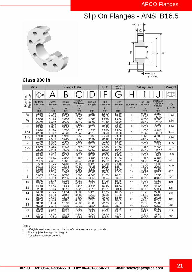
Slip On Flanges - ANSI B16.5
Pipe Flange Data Hub Raised Face Drilling Data Weight
Nom
inal
Outside Diameter
Overall Diameter
Inside Diameter
Flange Thickness
min Overall Length
Hub Diameter
Face Diameter
Number of
Holes
Bolt Hole Diameter
Diameter
of Holes
kg/
piece in mm
in mm
in mm
in mm
in mm
in mm
in mm
in mm
in mm
1/2 0.840 21.30
4.750 120.6
0.880 22.40
0.880 22.40
1.250 31.70
1.500 38.10
1.380 35.10 4 0.880
22.40 3.250 1.74
3/4 1.050 26.70
5.120 130.0
1.090 27.70
1.000 25.40
1.380 35.00
1.750 44.40
1.690 42.90 4 0.880
22.40 3.500 2.34
1 1.315 33.40
5.880 149.3
1.360 34.50
1.120 28.40
1.620 41.10
2.060 52.30
2.000 50.80 4 1.000
25.40 4.000 101.6 3.44
11/4 1.660 42.20
6.250 158.7
1.700 43.20
1.120 28.40
1.620 41.10
2.500 63.50
2.500 63.50 4 1.000
25.40 4.380 3.91
11/2 1.900 48.30
7.000 177.8
1.950 49.50
1.250 31.70
1.750 44.50
2.750 69.85
2.880 73.15 4 1.120
28.40 4.880 5.36
2 2.375 60.30
8.500 215.9
2.440 62.00
1.500 38.10
2.250 57.15
4.120 104.6
3.620 91.90 8 1.000
25.40 6.500 165.1 9.85
21/2 2.875 73.00
9.620 244.3
2.940 74.70
1.620 41.10
2.500 63.50
4.880 123.9
4.120 104.6 8 1.120
28.40 7.500 13.7
3 3.500 88.90
9.500 241.3
3.570 90.70
1.500 38.10
2.120 53.80
5.000 127.0
5.000 127.0 8 1.000
25.40 7.500 190.5 11.6
4 4.500 114.3
11.50 292.1
4.570 116.1
1.750 44.40
2.750 69.85
6.250 158.7
6.190 157.2 8 1.250
31.70 9.250 234.9 19.7
5 5.563 141.3
13.75 349.2
5.660 143.8
2.000 50.80
3.120 79.25
7.500 190.5
7.310 185.7 8 1.380
35.00 11.00 279.4 31.9
6 6.625 168.3
15.00 381.0
6.720 170.7
2.190 55.60
3.380 85.80
9.250 234.9
8.500 215.9 12 1.250
31.70 12.50 317.5 41.1
8 8.625 219.1
18.50 469.9
8.720 221.5
2.500 63.50
4.000 101.6
11.75 298.4
10.62 269.7 12 1.500
38.10 15.50 393.7 70.7
10 10.75 273.0
21.50 546.1
10.88 276.3
2.750 69.85
4.250 107.9
14.50 368.3
12.75 323.9 16 1.500
38.10 18.50 469.9 101
12 12.75 323.8
24.00 609.6
12.88 327.1
3.120 79.25
4.620 117.3
16.50 419.1
15.00 381.0 20 1.500
38.10 21.00 533.4 133
14 14.00 355.6
25.25 641.3
14.14 359.1
3.380 85.80
5.120 130.0
17.75 450.8
16.25 412.8 20 1.620
41.10 22.00 558.8 153
16 16.00 406.4
27.75 704.8
16.16 410.5
3.500 88.90
5.250 133.3
20.00 508.0
18.50 469.9 20 1.750
44.40 24.25 615.9 185
18 18.00 457.2
31.00 787.4
18.18 461.8
4.000 101.6
6.000 152.4
22.25 565.1
21.00 533.4 20 2.000
50.80 27.00 685.8 258
20 20.00 508.0
33.75 857.2
20.20 513.1
4.250 107.9
6.250 158.7
24.50 622.3
23.00 584.2 20 2.120
53.80 29.50 749.3 317
24 24.00 609.6
41.00 1041.4
24.25 616.0
5.500 139.7
8.000 203.2
29.50 749.3
27.25 692.2 20 2.620
66.55 35.50 901.7 606
Pip
e S
ize
Class 900 lb
of Circle
82.50
88.90
111.2
123.9
190.5
Notes - Weights are based on manufacturer’s data and are approximate. - For ring joint facings see page 6. - For tolerances see page 4.

APCO Flanges
Slip On Flanges - ANSI B16.5
22 APCO Tel: 86-431-88546619 Fax: 86-431-88546621 E-mail: [email protected]
Pipe Flange Data Hub Raised Face Drilling Data Weight
Nom
inal
Outside Diameter
Overall Diameter
Inside Diameter
Flange Thickness
min Overall Length
Hub Diameter
Face Diameter
Number of
Holes
Bolt Hole Diameter
Diameter
of Holes
kg/
piece in mm
in mm
in mm
in mm
in mm
in mm
in mm
in mm
in mm
1/2 0.840 21.30
4.750 120.6
0.880 22.40
0.880 22.40
1.250 31.70
1.500 38.10
1.380 35.10 4 0.880
22.40 3.250 1.74
3/4 1.050 26.70
5.120 130.0
1.090 27.70
1.000 25.40
1.380 35.00
1.750 44.40
1.690 42.90 4 0.880
22.40 3.500 2.34
1 1.315 33.40
5.880 149.3
1.360 34.50
1.120 28.40
1.620 41.10
2.060 52.30
2.000 50.80 4 1.000
25.40 4.000 101.6 3.44
11/4 1.660 42.20
6.250 158.7
1.700 43.20
1.120 28.40
1.620 41.10
2.500 63.50
2.500 63.50 4 1.000
25.40 4.380 3.91
11/2 1.900 48.30
7.000 177.8
1.950 49.50
1.250 31.70
1.750 44.50
2.750 69.85
2.880 73.15 4 1.120
28.40 4.880 5.36
2 2.375 60.30
8.500 215.9
2.440 62.00
1.500 38.10
2.250 57.15
4.120 104.6
3.620 91.90 8 1.000
25.40 6.500 165.1 9.85
21/2 2.875 73.00
9.620 244.3
2.940 74.70
1.620 41.10
2.500 63.50
4.880 123.9
4.120 104.6 8 1.120
28.40 7.500 13.7
Pip
e S
ize
Class 1500 lb
of Circle
82.50
88.90
111.2
123.9
190.5
Notes - Weights are based on manufacturer’s data and are approximate. - For ring joint facings see page 6. - For tolerances see page 4.

23 APCO Tel: 86-431-88546619 Fax: 86-431-88546621 E-mail: [email protected]
APCO Flanges
Blind Flanges - ANSI B16.5
Pipe Flange Data Raised Face Drilling Data Weight
N
omin
al
Pip
e S
ize
Outside Diameter
Overall Diameter
Flange Thickness
min Face
Diameter
Number of Holes
Bolt Hole Diameter
Diameter of Circle of
Holes
kg/piece in
mm in
mm in
mm in
mm in
mm in
mm 1/2 0.840
21.30 3.500 88.90
0.440 11.20
1.380 35.10 4 0.620
15.70 2.380 0.42
3/4 1.050 26.70
3.880 98.60
0.500 12.70
1.690 42.90 4 0.620
15.70 2.750 0.61
1 1.315 33.40
4.250 108.0
0.560 14.20
2.000 50.80 4 0.620
15.70 3.120 79.25 0.86
11/4 1.660 42.20
4.620 117.3
0.620 15.70
2.500 63.50 4 0.620
15.70 3.500 1.17
11/2 1.900 48.30
5.000 127.0
0.690 17.50
2.880 73.15 4 0.620
15.70 3.880 1.53
2 2.375 60.30
6.000 152.4
0.750 19.10
3.620 91.90 4 0.750
19.10 4.750 120.7 2.42
21/2 2.875 73.00
7.000 177.8
0.880 22.40
4.120 104.6 4 0.750
19.10 5.500 3.94
3 3.500 88.90
7.500 190.5
0.940 23.90
5.000 127.0 4 0.750
19.10 6.000 152.4 4.93
31/2 4.000 101.6
8.500 215.9
0.940 23.90
5.500 139.7 8 0.750
19.10 7.000 6.17
4 4.500 114.3
9.000 228.6
0.940 23.90
6.190 157.2 8 0.750
19.10 7.500 190.5 7.00
5 5.563 141.3
10.00 254.0
0.940 23.90
7.310 185.7 8 0.880
22.40 8.500 215.9 8.63
6 6.625 168.3
11.00 279.4
1.000 25.40
8.500 215.9 8 0.880
22.40 9.500 241.3 11.3
8 8.625 219.1
13.50 342.9
1.120 28.40
10.62 269.7 8 0.880
22.40 11.75 298.5 19.6
10 10.75 273.0
16.00 406.4
1.190 30.20
12.75 323.9 12 1.000
25.40 14.25 362.0 28.8
12 12.75 323.8
19.00 482.6
1.250 31.75
15.00 381.0 12 1.000
25.40 17.00 431.8 43.2
14 14.00 355.6
21.00 533.4
1.380 35.10
16.25 412.8 12 1.120
28.40 18.75 476.3 58.1
16 16.00 406.4
23.50 596.9
1.440 36.60
18.50 469.9 16 1.120
28.40 21.25 539.8 76.0
18 18.00 457.2
25.00 635.0
1.560 39.60
21.00 533.4 16 1.250
31.75 22.75 577.9 93.7
20 20.00 508.0
27.50 698.5
1.690 42.90
23.00 584.2 20 1.250
31.75 25.00 635.0 122
24 24.00 609.6
32.00 812.8
1.880 47.80
27.25 692.2 20 1.380
35.10 29.50 749.3 185
Class 150 lb
60.45
69.85
88.90
98.60
139.7
177.8
Notes - Weights are based on manufacturer’s data and are approximate. - Flat face flanges may be provided at full thickness, C, or with raised face removed (the latter is nonstandard). - For ring joint facings see page 6. - For tolerances see page 4.

APCO Flanges
Blind Flanges - ANSI B16.5
24 APCO Tel: 86-431-88546619 Fax: 86-431-88546621 E-mail: [email protected]
Pipe Flange Data Raised Face Drilling Data Weight
N
omin
al
Pip
e S
ize
Outside Diameter
Overall Diameter
Flange Thickness
min Face
Diameter
Number of Holes
Bolt Hole Diameter
Diameter of Circle of
Holes
kg/piece in
mm in
mm in
mm in
mm in
mm in
mm 1/2 0.840
21.30 3.750 95.20
0.560 14.20
1.380 35.10 4 0.620
15.70 2.620 0.64
3/4 1.050 26.70
4.620 117.3
0.620 15.70
1.690 42.90 4 0.750
19.00 3.250 1.11
1 1.315 33.40
4.880 123.9
0.690 17.50
2.000 50.80 4 0.750
19.00 3.500 88.90 1.39
11/4 1.660 42.20
5.250 133.3
0.750 19.00
2.500 63.50 4 0.750
19.00 3.880 1.79
11/2 1.900 48.30
6.120 155.4
0.810 20.60
2.880 73.15 4 0.880
22.3 4.500 2.66
2 2.375 60.30
6.500 165.1
0.880 22.30
3.620 91.90 8 0.750
19.10 5.000 127.0 3.18
21/2 2.875 73.00
7.500 190.5
1.000 25.40
4.120 104.6 8 0.880
22.30 5.880 4.85
3 3.500 88.90
8.250 209.5
1.120 28.40
5.000 127.0 8 0.880
22.30 6.620 168.1 6.81
31/2 4.000 101.6
9.000 228.6
1.190 30.20
5.500 139.7 8 0.880
22.30 7.250 8.71
4 4.500 114.3
10.00 254.0
1.250 31.70
6.190 157.2 8 0.880
22.30 7.800 200.1 11.5
5 5.563 141.3
11.00 279.4
1.380 35.00
7.310 185.7 8 0.880
22.30 9.250 234.9 15.6
6 6.625 168.3
12.50 317.5
1.440 36.50
8.500 215.9 12 0.880
22.30 10.62 269.7 20.9
8 8.625 219.1
15.00 381.0
1.620 41.10
10.62 269.7 12 1.000
25.40 13.00 330.2 34.3
10 10.75 273.0
17.50 444.5
1.880 47.70
12.75 323.9 16 1.120
28.40 15.25 387.3 53.3
12 12.75 323.8
20.50 520.7
2.000 50.80
15.00 381.0 16 1.250
31.70 17.75 450.8 78.8
14 14.00 355.6
23.00 584.2
2.120 53.80
16.25 412.8 20 1.250
31.70 20.25 514.3 105
16 16.00 406.4
25.50 647.7
2.250 57.15
18.50 469.9 20 1.380
35.00 22.50 571.5 137
18 18.00 457.2
28.00 711.2
2.380 60.45
21.00 533.4 24 1.380
35.00 24.75 628.6 175
20 20.00 508.0
30.50 774.7
2.500 63.50
23.00 584.2 24 1.380
35.00 27.00 685.8 221
24 24.00 609.6
36.00 914.4
2.750 69.85
27.25 692.2 24 1.620
41.10 32.00 812.8 339
Class 300 lb
66.55
82.50
98.50
114.3
1.493
184.1
Notes - Weights are based on manufacturer’s data and are approximate. - Flat face flanges may be provided at full thickness, C, or with raised face removed (the latter is nonstandard). - For ring joint facings see page 6. - For tolerances see page 4.

25 APCO Tel: 86-431-88546619 Fax: 86-431-88546621 E-mail: [email protected]
APCO Flanges
Blind Flanges - ANSI B16.5
Pipe Flange Data Raised Face Drilling Data Weight
N
omin
al
Pip
e S
ize
Outside Diameter
Overall Diameter
Flange Thickness
min Face
Diameter
Number of Holes
Bolt Hole Diameter
Diameter of Circle of
Holes
kg/piece in
mm in
mm in
mm in
mm in
mm in
mm 1/2 0.840
21.30 3.750 95.20
0.560 14.20
1.380 35.10 4 0.620
15.70 2.620 0.76
3/4 1.050 26.70
4.620 117.3
0.620 15.70
1.690 42.90 4 0.750
19.10 3.250 1.28
1 1.315 33.40
4.880 123.9
0.690 17.50
2.000 50.80 4 0.750
19.10 3.500 88.90 1.60
11/4 1.660 42.20
5.250 133.3
0.810 20.60
2.500 63.50 4 0.750
19.10 3.880 2.23
11/2 1.900 48.30
6.120 155.4
0.880 22.30
2.880 73.15 4 0.880
22.40 4.500 3.25
2 2.375 60.30
6.500 165.1
1.000 25.40
3.620 91.90 8 0.750
19.10 5.000 127.0 4.15
21/2 2.875 73.00
7.500 190.5
1.120 28.40
4.120 104.6 8 0.880
22.40 5.880 6.13
3 3.500 88.90
8.250 209.5
1.250 31.70
5.000 127.0 8 0.880
22.40 6.620 168.1 8.44
31/2 4.000 101.6
9.000 228.6
1.380 35.00
5.500 139.7 8 1.000
25.40 7.250 11.0
4 4.500 114.3
10.00 254.0
1.380 35.10
6.190 157.2 8 1.000
25.40 7.880 200.2 13.7
5 5.563 141.3
11.00 279.4
1.500 38.10
7.310 185.7 8 1.000
25.40 9.250 235.0 18.5
6 6.625 168.3
12.50 317.5
1.620 41.10
8.500 215.9 12 1.000
25.40 10.62 269.7 25.5
8 8.625 219.1
15.00 381.0
1.880 47.80
10.62 269.7 12 1.120
28.40 13.00 330.2 42.6
10 10.75 273.0
17.50 444.5
2.120 53.80
12.75 323.9 16 1.250
31.75 15.25 387.4 64.5
12 12.75 323.8
20.50 520.7
2.250 57.15
15.00 381.0 16 1.380
35.10 17.75 450.9 94.30
14 14.00 355.6
23.00 584.2
2.380 60.45
16.25 412.8 20 1.380
35.10 20.25 514.4 124
16 16.00 406.4
25.50 647.7
2.500 63.50
18.50 469.9 20 1.500
38.10 22.50 571.5 162
18 18.00 457.2
28.00 711.2
2.620 66.55
21.00 533.4 24 1.500
38.10 24.75 628.7 205
20 20.00 508.0
30.50 774.7
2.750 69.85
23.00 584.2 24 1.620
41.10 27.00 685.8 254
24 24.00 609.6
36.00 914.4
3.000 76.20
27.25 692.2 24 1.880
47.80 32.00 812.8 386
Class 400 lb
66.55
82.60
98.60
114.3
149.4
184.2
Notes - Weights are based on manufacturer’s data and are approximate. - For ring joint facings see page 6. - For tolerances see page 4.

APCO Flanges
Blind Flanges - ANSI B16.5
26 APCO Tel: 86-431-88546619 Fax: 86-431-88546621 E-mail: [email protected]
Pipe Flange Data Raised Face Drilling Data Weight
N
omin
al
Pip
e S
ize
Outside Diameter
Overall Diameter
Flange Thickness
min Face
Diameter
Number of Holes
Bolt Hole Diameter
Diameter of Circle of
Holes
kg/piece in
mm in
mm in
mm in
mm in
mm in
mm 1/2 0.840
21.30 3.750 95.20
0.560 14.20
1.380 35.10 4 0.620
15.70 2.620 0.76
3/4 1.050 26.70
4.620 117.3
0.620 15.70
1.690 42.90 4 0.750
19.10 3.250 1.28
1 1.315 33.40
4.880 123.9
0.690 17.50
2.000 50.80 4 0.750
19.10 3.500 88.90 1.60
11/4 1.660 42.20
5.250 133.3
0.810 20.60
2.500 63.50 4 0.750
19.10 3.880 2.23
11/2 1.900 48.30
6.120 155.4
0.880 22.30
2.880 73.15 4 0.880
22.40 4.500 3.25
2 2.375 60.30
6.500 165.1
1.000 25.40
3.620 91.90 8 0.750
19.10 5.000 127.0 4.15
21/2 2.875 73.00
7.500 190.5
1.120 28.40
4.120 104.6 8 0.880
22.40 5.880 6.13
3 3.500 88.90
8.250 209.5
1.250 31.70
5.000 127.0 8 0.880
22.40 6.620 168.1 8.44
31/2 4.000 101.6
9.000 228.6
1.380 35.00
5.500 139.7 8 1.000
25.40 7.250 11.0
4 4.500 114.3
10.75 273.1
1.500 38.10
6.190 157.2 8 1.000
25.40 8.500 215.9 17.3
5 5.563 141.3
13.00 330.2
1.750 44.50
7.310 185.7 8 1.120
28.40 10.50 266.7 29.4
6 6.625 168.3
14.00 355.6
1.880 47.80
8.500 215.9 12 1.120
28.40 11.50 292.1 36.1
8 8.625 219.1
16.50 419.1
2.190 55.60
10.62 269.7 12 1.250
31.75 13.75 349.3 58.9
10 10.75 273.0
20.00 508.0
2.500 63.50
12.75 323.9 16 1.380
35.10 17.00 431.8 97.5
12 12.75 323.8
22.00 558.8
2.620 66.55
15.00 381.0 20 1.380
35.10 19.25 489.0 124
14 14.00 355.6
23.75 603.3
2.750 69.85
16.25 412.8 20 1.500
38.10 20.75 527.1 151
16 16.00 406.4
27.00 685.8
3.000 76.20
18.50 469.9 20 1.620
41.10 23.75 603.3 214
18 18.00 457.2
29.25 743.0
3.250 82.60
21.00 533.4 20 1.750
44.50 25.75 654.1 272
20 20.00 508.0
32.00 812.8
3.500 88.90
23.00 584.2 24 1.750
44.50 28.50 723.9 349
24 24.00 609.6
37.00 939.8
4.000 101.6
27.25 692.2 24 2.000
50.80 33.00 838.2 533
Class 600 lb
66.55
82.60
98.60
114.3
149.4
184.2
Notes - Weights are based on manufacturer’s data and are approximate. - For ring joint facings see page 6. - For tolerances see page 4.

27 APCO Tel: 86-431-88546619 Fax: 86-431-88546621 E-mail: [email protected]
APCO Flanges
Blind Flanges - ANSI B16.5
Pipe Flange Data Raised Face Drilling Data Weight
N
omin
al
Pip
e S
ize
Outside Diameter
Overall Diameter
Flange Thickness
min Face
Diameter
Number of Holes
Bolt Hole Diameter
Diameter of Circle of
Holes
kg/piece in
mm in
mm in
mm in
mm in
mm in
mm 1/2 0.840
21.30 4.750 120.6
0.880 22.30
1.380 35.10 4 0.880
22.30 3.250 1.77
3/4 1.050 26.70
5.120 130.0
1.000 25.40
1.690 42.90 4 0.880
22.30 3.500 2.42
1 1.315 33.40
5.880 149.3
1.120 28.40
2.000 50.80 4 1.000
25.40 4.000 101.6 3.57
11/4 1.660 42.20
6.250 158.7
1.120 28.40
2.500 63.50 4 1.000
25.40 4.380 4.15
11/2 1.900 48.30
7.000 177.8
1.250 31.70
2.880 73.15 4 1.120
28.40 4.880 5.75
2 2.375 60.30
8.500 215.9
1.500 38.10
3.620 91.90 8 1.000
25.40 6.500 165.1 10.1
21/2 2.875 73.00
9.620 244.3
1.620 41.10
4.120 104.6 8 1.120
28.40 7.500 14.0
3 3.500 88.90
9.500 241.3
1.500 38.10
5.000 127.0 8 1.000
25.40 7.500 190.5 13.1
4 4.500 114.3
11.50 292.1
1.750 44.50
6.190 157.2 8 1.250
31.70 9.250 234.9 26.9
5 5.563 141.3
13.75 349.2
2.000 50.80
7.310 185.7 8 1.380
35.00 11.00 279.4 36.5
6 6.625 168.3
15.00 381.0
2.190 55.60
8.500 215.9 12 1.250
31.70 12.50 317.0 47.40
8 8.625 219.1
18.50 469.9
2.500 63.50
10.62 269.7 12 1.500
38.10 15.50 393.7 82.5
10 10.75 273.0
21.50 546.1
2.750 69.85
12.75 323.9 16 1.500
38.10 18.50 469.9 122
12 12.75 323.8
24.00 609.6
3.120 79.25
15.00 381.0 20 1.500
38.10 21.00 533.4 173
14 14.00 355.6
25.25 641.3
3.380 85.80
16.25 412.8 20 1.620
41.10 22.00 558.8 206
16 16.00 406.4
27.75 704.8
3.500 88.90
18.50 469.9 20 1.750
44.40 24.25 615.9 259
18 18.00 457.2
31.00 787.4
4.000 101.6
21.00 533.4 20 2.000
50.80 27.00 685.8 367
20 20.00 508.0
33.75 857.2
4.250 107.9
23.00 584.2 20 2.120
53.80 29.50 749.3 463
24 24.00 609.6
41.00 1041.4
5.500 139.7
27.25 692.2 20 2.620
66.55 35.50 901.7 876
Class 900 lb
82.50
88.90
111.2
123.9
190.5
Notes - Weights are based on manufacturer’s data and are approximate. - For ring joint facings see page 6. - For tolerances see page 4.

APCO Flanges
Blind Flanges - ANSI B16.5
28 APCO Tel: 86-431-88546619 Fax: 86-431-88546621 E-mail: [email protected]
Pipe Flange Data Raised Face Drilling Data Weight
N
omin
al
Pip
e S
ize
Outside Diameter
Overall Diameter
Flange Thickness
min Face
Diameter
Number of Holes
Bolt Hole Diameter
Diameter of Circle of
Holes
kg/piece in
mm in
mm in
mm in
mm in
mm in
mm 1/2 0.840
21.30 4.750 120.6
0.880 22.30
1.380 35.10 4 0.880
22.30 3.250 1.77
3/4 1.050 26.70
5.120 130.0
1.000 25.40
1.690 42.90 4 0.880
22.30 3.500 2.42
1 1.315 33.40
5.880 149.3
1.120 28.40
2.000 50.80 4 1.000
25.40 4.000 101.6 3.57
11/4 1.660 42.20
6.250 158.7
1.120 28.40
2.500 63.50 4 1.000
25.40 4.380 4.15
11/2 1.900 48.30
7.000 177.8
1.250 31.70
2.880 73.15 4 1.120
28.40 4.880 5.75
2 2.375 60.30
8.500 215.9
1.500 38.10
3.620 91.90 8 1.000
25.40 6.500 165.1 10.1
21/2 2.875 73.00
9.620 244.3
1.620 41.10
4.120 104.6 8 1.120
28.40 7.500 14.0
3 3.500 88.90
10.50 266.7
1.880 47.70
5.000 127.0 8 1.250
31.70 8.000 203.2 19.1
4 4.500 114.3
12.25 311.1
2.120 53.80
6.190 157.2 8 1.380
35.00 9.500 241.3 29.9
5 5.563 141.3
14.75 374.6
2.880 73.15
7.310 185.7 8 1.620
41.10 11.50 292.1 58.4
6 6.625 168.3
15.50 393.7
3.250 82.50
8.500 215.9 12 1.500
38.10 12.50 317.5 71.8
8 8.625 219.1
19.00 482.6
3.620 91.90
10.62 269.7 12 1.750
44.40 15.50 393.7 122
10 10.75 273.0
23.00 584.2
4.250 107.9
12.75 323.9 12 2.000
50.80 19.00 482.6 210
12 12.75 323.8
26.50 673.1
4.880 123.9
15.00 381.0 16 2.120
53.8 22.50 571.5 316
14 14.00 355.6
29.50 749.3
5.250 133.3
16.25 412.8 16 2.380
60.45 25.00 635.0 420
16 16.00 406.4
32.50 825.5
5.750 146.0
18.50 469.9 16 2.620
66.55 27.75 704.8 558
18 18.00 457.2
36.00 914.4
6.380 162.0
21.00 533.4 16 2.880
73.15 30.50 774.7 760
20 20.00 508.0
38.75 984.2
7.000 177.8
23.00 584.2 16 3.120
79.25 32.75 831.8 965
24 24.00 609.6
46.00 1168.4
8.000 203.2
27.25 692.2 16 3.620
91.90 39.00 990.6 1558
Class 1500 lb
82.50
88.90
111.2
123.9
190.5
Notes - Weights are based on manufacturer’s data and are approximate. - For ring joint facings see page 6. - For tolerances see page 4.

29 APCO Tel: 86-431-88546619 Fax: 86-431-88546621 E-mail: [email protected]
APCO Flanges
Blind Flanges - ANSI B16.5
Pipe Flange Data Raised Face Drilling Data Weight
N
omin
al
Pip
e S
ize
Outside Diameter
Overall Diameter
Flange Thickness
min Face
Diameter
Number of Holes
Bolt Hole Diameter
Diameter of Circle of
Holes
kg/piece in
mm in
mm in
mm in
mm in
mm in
mm 1/2 0.840
21.30 5.250 133.4
1.190 30.20
1.380 35.10 4 0.880
22.40 3.500 2.99
3/4 1.050 26.70
5.500 139.7
1.250 31.70
1.690 42.90 4 0.880
22.40 3.750 3.50
1 1.315 33.40
6.250 158.8
1.380 35.10
2.000 50.80 4 1.000
25.40 4.250 108.0 4.96
11/4 1.660 42.20
7.250 184.2
1.500 38.10
2.500 63.50 4 1.120
28.40 5.120 7.35
11/2 1.900 48.30
8.000 203.2
1.750 44.50
2.880 73.15 4 1.250
31.75 5.750 10.4
2 2.375 60.30
9.250 235.0
2.000 50.80
3.620 91.90 8 1.120
28.40 6.750 171.5 15.6
21/2 2.875 73.00
10.50 266.7
2.250 57.15
4.120 104.6 8 1.250
31.75 7.750 22.6
3 3.500 88.90
12.00 304.8
2.620 66.55
5.000 127.0 8 1.380
35.10 9.000 228.6 34.8
4 4.500 114.3
14.00 355.6
3.000 76.20
6.190 157.2 8 1.620
41.10 10.75 273.1 53.9
5 5.563 141.3
16.50 419.1
3.620 91.90
7.310 185.7 8 1.888
47.88 12.75 323.9 90.8
6 6.625 168.3
19.00 482.6
4.250 108.0
8.500 215.9 8 2.120
53.80 14.50 368.3 141
8 8.625 219.1
21.75 552.5
5.000 127.0
10.62 269.7 12 2.120
53.80 17.25 438.2 214
10 10.75 273.0
26.50 673.1
6.500 165.1
12.75 323.9 12 2.620
66.55 21.25 539.8 411
12 12.75 323.8
30.00 762.0
7.250 184.2
15.00 381.0 12 2.880
73.15 24.38 619.3 592
Class 2500 lb
88.90
95.30
130.0
146.1
196.9
Notes - Weights are based on manufacturer’s data and are approximate. - For ring joint facings see page 6. - For tolerances see page 4.
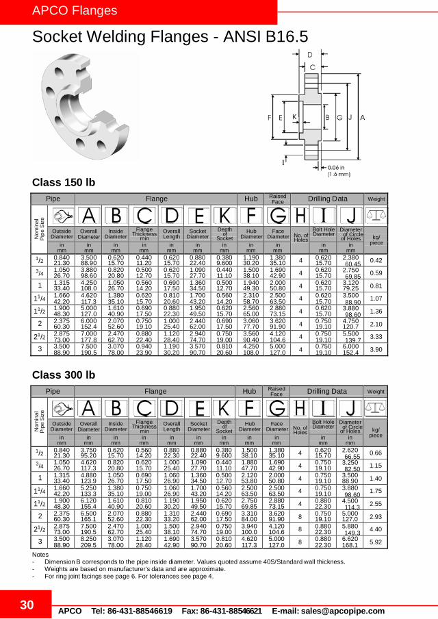
APCO Flanges
Socket Welding Flanges - ANSI B16.5
30 APCO Tel: 86-431-88546619 Fax: 86-431-88546621 E-mail: [email protected]
Pipe Flange Hub Raised Face Drilling Data Weight
Nom
inal
P
ipe
Siz
e
Outside Diameter
Overall Diameter
Inside Diameter
Flange Thickness
min Overall Length
Socket Diameter
Depth of
Socket Hub
Diameter Face
Diameter No. of Holes
Bolt Hole Diameter
Diameter of Holes
kg/
piece in mm
in mm
in mm
in mm
in mm
in mm
in mm
in mm
in mm
in mm
in mm
1/2 0.840 21.30
3.500 88.90
0.620 15.70
0.440 11.20
0.620 15.70
0.880 22.40
0.380 9.600
1.190 30.20
1.380 35.10 4 0.620
15.70 2.380 0.42
3/4 1.050 26.70
3.880 98.60
0.820 20.80
0.500 12.70
0.620 15.70
1.090 27.70
0.440 11.10
1.500 38.10
1.690 42.90 4 0.620
15.70 2.750 0.59
1 1.315 33.40
4.250 108.0
1.050 26.70
0.560 14.20
0.690 17.50
1.360 34.50
0.500 12.70
1.940 49.30
2.000 50.80 4 0.620
15.70 3.120 79.25 0.81
11/4 1.660 42.20
4.620 117.3
1.380 35.10
0.620 15.70
0.810 20.60
1.700 43.20
0.560 14.20
2.310 58.70
2.500 63.50 4 0.620
15.70 3.500 1.07
11/2 1.900 48.30
5.000 127.0
1.610 40.90
0.690 17.50
0.880 22.30
1.950 49.50
0.620 15.70
2.560 65.00
2.880 73.15 4 0.620
15.70 3.880 1.36
2 2.375 60.30
6.000 152.4
2.070 52.60
0.750 19.10
1.000 25.40
2.440 62.00
0.690 17.50
3.060 77.70
3.620 91.90 4 0.750
19.10 4.750 120.7 2.10
21/2 2.875 73.00
7.000 177.8
2.470 62.70
0.880 22.40
1.120 28.40
2.940 74.70
0.750 19.00
3.560 90.40
4.120 104.6 4 0.750
19.10 5.500 3.33
3 3.500 88.90
7.500 190.5
3.070 78.00
0.940 23.90
1.190 30.20
3.570 90.70
0.810 20.60
4.250 108.0
5.000 127.0 4 0.750
19.10 6.000 152.4 3.90
Pipe Flange Hub Raised Face Drilling Data Weight
Nom
inal
P
ipe
Siz
e
Outside Diameter
Overall Diameter
Inside Diameter
Flange Thickness
min Overall Length
Socket Diameter
Depth of
Socket Hub
Diameter Face
Diameter No. of Holes
Bolt Hole Diameter
Diameter of Holes
kg/
piece in mm
in mm
in mm
in mm
in mm
in mm
in mm
in mm
in mm
in mm
in mm
1/2 0.840 21.30
3.750 95.20
0.620 15.70
0.560 14.20
0.880 22.30
0.880 22.40
0.380 9.600
1.500 38.10
1.380 35.10 4 0.620
15.70 2.620 0.66
3/4 1.050 26.70
4.620 117.3
0.820 20.80
0.620 15.70
1.000 25.40
1.090 27.70
0.440 11.10
1.880 47.70
1.690 42.90 4 0.750
19.10 3.250 1.15
1 1.315 33.40
4.880 123.9
1.050 26.70
0.690 17.50
1.060 26.90
1.360 34.50
0.500 12.70
2.120 53.80
2.000 50.80 4 0.750
19.10 3.500 88.90 1.40
11/4 1.660 42.20
5.250 133.3
1.380 35.10
0.750 19.00
1.060 26.90
1.700 43.20
0.560 14.20
2.500 63.50
2.500 63.50 4 0.750
19.10 3.880 1.75
11/2 1.900 48.30
6.120 155.4
1.610 40.90
0.810 20.60
1.190 30.20
1.950 49.50
0.620 15.70
2.750 69.85
2.880 73.15 4 0.880
22.30 4.500 2.55
2 2.375 60.30
6.500 165.1
2.070 52.60
0.880 22.30
1.310 33.20
2.440 62.00
0.690 17.50
3.310 84.00
3.620 91.90 8 0.750
19.10 5.000 127.0 2.93
21/2 2.875 73.00
7.500 190.5
2.470 62.70
1.000 25.40
1.500 38.10
2.940 74.70
0.750 19.00
3.940 100.0
4.120 104.6 8 0.880
22.30 5.880 4.40
3 3.500 88.90
8.250 209.5
3.070 78.00
1.120 28.40
1.690 42.90
3.570 90.70
0.810 20.60
4.620 117.3
5.000 127.0 8 0.880
22.30 6.620 168.1 5.92
Class 150 lb
of Circle
60.45
69.85
88.90
98.60
139.7
Class 300 lb
of Circle
66.55
82.50
98.60
114.3
149.3
Notes - Dimension B corresponds to the pipe inside diameter. Values quoted assume 40S/Standard wall thickness. - Weights are based on manufacturer’s data and are approximate. - For ring joint facings see page 6. For tolerances see page 4.

31 APCO Tel: 86-431-88546619 Fax: 86-431-88546621 E-mail: [email protected]
APCO Flanges
Socket Welding Flanges - ANSI B16.5
Pipe Flange Hub Raised Face Drilling Data Weight
Nom
inal
P
ipe
Siz
e
Outside Diameter
Overall Diameter
Inside Diameter
Flange Thickness
min Overall Length
Socket Diameter
Depth of
Socket Hub
Diameter Face
Diameter No. of Holes
Bolt Hole Diameter
Diameter of Holes
kg/
piece in mm
in mm
in mm
in mm
in mm
in mm
in mm
in mm
in mm
in mm
in mm
1/2 0.840 21.30
3.750 95.20
To
be
spec
ified
by
the
Pur
chas
er
0.560 14.20
0.880 22.30
0.880 22.40
0.380 9.600
1.500 38.10
1.380 35.10 4 0.620
15.70 2.620 0.76
3/4 1.050 26.70
4.620 117.3
0.620 15.70
1.000 25.40
1.090 27.70
0.440 11.10
1.880 47.70
1.690 42.90 4 0.750
19.10 3.250 1.29
1 1.315 33.40
4.880 123.9
0.690 17.50
1.060 26.90
1.360 34.50
0.500 12.70
2.120 53.80
2.000 50.80 4 0.750
19.10 3.500 88.90 1.55
11/4 1.660 42.20
5.250 133.3
0.810 20.60
1.120 28.40
1.700 43.20
0.560 14.20
2.500 63.50
2.500 63.50 4 0.750
19.10 3.880 2.06
11/2 1.900 48.30
6.120 155.4
0.880 22.30
1.250 31.75
1.950 49.50
0.620 15.70
2.750 69.85
2.880 73.15 4 0.880
22.30 4.500 3.00
2 2.375 60.30
6.500 165.1
1.000 25.40
1.440 36.60
2.440 62.00
0.690 17.50
3.310 84.00
3.620 91.90 8 0.750
19.10 5.000 127.0 3.67
21/2 2.875 73.00
7.500 190.5
1.120 28.40
1.620 41.10
2.940 74.70
0.750 19.00
3.940 100.0
4.120 104.6 8 0.880
22.30 5.880 5.35
3 3.500 88.90
8.250 209.5
1.250 31.75
1.810 46.00
3.570 90.70
0.810 20.60
4.620 117.3
5.000 127.0 8 0.880
22.30 6.620 168.1 7.06
Pipe Flange Hub Raised Face Drilling Data Weight
Nom
inal
Outside Diameter
Overall Diameter
Inside Diameter
Flange Thickness
min Overall Length
Socket Diameter
Depth of
Socket Hub
Diameter Face
Diameter No. of Holes
Bolt Hole Diameter
Diameter of Holes
kg/
piece in mm
in mm
in mm
in mm
in mm
in mm
in mm
in mm
in mm
in mm
in mm
1/2 0.840 21.30
4.750 120.6
To
be
spec
ified
by
0.880 22.30
1.250 31.70
0.880 22.40
0.380 9.600
1.500 38.10
1.380 35.10 4 0.880
22.30 3.250 1.80
3/4 1.050 26.70
5.120 130.0
1.000 25.40
1.380 35.00
1.090 27.70
0.440 11.10
1.750 44.40
1.690 42.90 4 0.880
22.30 3.500 2.41
1 1.315 33.40
5.880 149.3
1.120 28.40
1.620 41.10
1.360 34.50
0.500 12.70
2.060 52.30
2.000 50.80 4 1.000
25.40 4.000 101.6 3.55
11/4 1.660 42.20
6.250 158.7
1.120 28.40
1.620 41.10
1.700 43.20
0.560 14.20
2.500 63.50
2.500 63.50 4 1.000
25.40 4.380 4.02
11/2 1.900 48.30
7.000 177.8
1.250 31.75
1.750 44.50
1.950 49.50
0.620 15.70
2.750 69.85
2.880 73.15 4 1.120
28.40 4.880 5.45
2 2.375 60.30
8.500 215.9
1.500 38.10
2.250 57.15
2.440 62.00
0.690 17.50
4.120 104.6
3.620 91.90 8 1.000
25.40 6.500 165.1 10.2
21/2 2.875 73.00
9.620 244.3
1.620 41.10
2.500 63.50
2.940 74.70
0.750 19.00
4.880 123.9
4.120 104.6 8 1.120
28.40 7.500 13.9
Pip
e S
ize
the
Purc
hase
r
Class 600 lb
of Circle
66.55
82.50
98.60
114.3
149.3
Class 1500 lb
of Circle
82.50
88.90
111.2
123.9
Notes - Class 400 socket weld flanges may be provided in NPS 1/2 to 21/2 using Class 600 dimensions
190.5
- Dimension B corresponds to the pipe inside diameter. Values quoted assume 40S/Standard wall thickness. - Weights are based on manufacturer’s data and are approximate. - For ring joint facings see page 6. For tolerances see page 4.

APCO Flanges
Lap Joint Flanges - ANSI B16.5
32 APCO Tel: 86-431-88546619 Fax: 86-431-88546621 E-mail: [email protected]
Pipe Flange Data Lap Hub Drilling Data Weight
Nom
inal
OutsideDiameter
OverallDiameter
InsideDiameter
FlangeThickness
minOverallLength
LapRadius
HubDiameter
Number of Holes
Bolt HoleDiameter
Diameter
of Holes
kg/
piecein mm
in mm
in mm
in mm
in mm
in mm
in mm
in mm
in mm
1/2 0.84021.30
3.50088.90
0.90022.90
0.44011.20
0.62015.70
0.1203.000
1.19030.20 4 0.620
15.702.380 0.38
3/4 1.05026.70
3.88098.60
1.11028.20
0.50012.70
0.62015.70
0.1203.000
1.50038.10 4 0.620
15.702.750 0.55
1 1.31533.40
4.250108.0
1.38035.10
0.56014.20
0.69017.50
0.1203.000
1.94049.30 4 0.620
15.703.12079.25 0.76
11/4 1.66042.20
4.620117.3
1.72043.70
0.62015.70
0.81020.60
0.1904.800
2.31058.70 4 0.620
15.703.500 1.01
11/2 1.90048.30
5.000127.0
1.97050.00
0.69017.50
0.88022.40
0.2506.400
2.56065.00 4 0.620
15.703.880 1.30
2 2.37560.30
6.000152.4
2.46062.50
0.75019.10
1.00025.40
0.3107.900
3.06077.70 4 0.750
19.104.750120.7 2.03
21/2 2.87573.00
7.000177.8
2.97075.40
0.88022.40
1.12028.40
0.3107.900
3.56090.40 4 0.750
19.105.500 3.25
3 3.50088.90
7.500190.5
3.60091.40
0.94023.90
1.19030.20
0.3809.700
4.250108.0 4 0.750
19.106.000152.4 3.81
31/2 4.000101.6
8.500215.9
4.100104.1
0.94023.90
1.25031.75
0.3809.700
4.810122.2 8 0.750
19.107.000 4.76
4 4.500114.3
9.000228.6
4.600116.8
0.94023.90
1.31033.30
0.44011.20
5.310134.9 8 0.750
19.107.500190.5 5.25
5 5.563141.3
10.00254.0
5.690114.5
0.94023.90
1.44036.60
0.44011.20
6.440163.6 8 0.880
22.408.500215.9 6.02
6 6.625168.3
11.00279.4
6.750171.5
1.00025.40
1.56039.60
0.50012.70
7.560192.0 8 0.880
22.409.500241.3 7.40
8 8.625219.1
13.50342.9
8.750222.3
1.12028.40
1.75044.50
0.50012.70
9.690246.1 8 0.880
22.4011.75298.5 12.1
10 10.75273.0
16.00406.4
10.92277.4
1.19030.20
1.94049.30
0.50012.70
12.00304.8 12 1.000
25.4014.25362.0 16.4
12 12.75323.8
19.00482.6
12.92328.2
1.25031.75
2.19055.60
0.50012.70
14.38365.3 12 1.000
25.4017.00431.8 26.1
14 14.00355.6
21.00533.4
14.18360.2
1.38035.10
3.12079.25
0.50012.70
15.75400.1 12 1.120
28.4018.75476.3 34.5
16 16.00406.4
23.50596.9
16.19411.2
1.44036.60
3.44087.40
0.50012.70
18.00457.2 16 1.120
28.4021.25539.8 44.6
18 18.00457.2
25.00635.0
18.20462.3
1.56039.60
3.81096.80
0.50012.70
19.88505.0 16 1.250
31.7522.75577.9 48.7
20 20.00508.0
27.50698.5
20.25514.4
1.69042.90
4.060103.1
0.50012.70
22.00558.8 20 1.250
31.7525.00635.0 61.6
24 24.00609.6
32.00812.8
24.25616.0
1.88047.80
4.380111.3
0.50012.70
26.12663.4 20 1.380
35.1029.50749.3 86.6
Pip
eS
ize
Class 150 lb
of Circle
60.45
69.85
88.90
98.60
139.7
177.8
Notes- Weights are based on manufacturer’s data and are approximate.- For tolerances see page 4.

33APCO Tel: 86-431-88546619 Fax: 86-431-88546621 E-mail: [email protected]
APCO Flanges
Lap Joint Flanges - ANSI B16.5
Pipe Flange Data Lap Hub Drilling Data Weight
Nom
inal
Pip
eS
ize
OutsideDiameter
OverallDiameter
InsideDiameter
FlangeThickness
minOverallLength
LapRadius
HubDiameter
Number of Holes
Bolt HoleDiameter
Diameter
of Holes
kg/
piecein mm
in mm
in mm
in mm
in mm
in mm
in mm
in mm
in mm
1/2 0.84021.30
3.75095.20
0.90022.90
0.56014.20
0.88022.30
0.1203.000
1.50038.10 4 0.620
15.702.620 0.62
3/4 1.05026.70
4.620117.3
1.11028.20
0.62015.70
1.00025.40
0.1203.000
1.88047.70 4 0.750
19.003.250 1.10
1 1.31533.40
4.880123.9
1.38035.10
0.69017.50
1.06026.90
0.1203.000
2.12053.80 4 0.750
19.03.50088.90 1.33
11/4 1.66042.20
5.250133.3
1.72043.70
0.75019.00
1.06026.90
0.1904.800
2.50063.50 4 0.750
19.003.880 1.65
11/2 1.90048.30
6.120155.4
1.97050.00
0.81020.60
1.19030.20
0.2506.400
2.75069.85 4 0.880
22.304.500 2.44
2 2.37560.30
6.500165.1
2.46062.50
0.88022.30
1.31033.20
0.3107.900
3.31084.00 8 0.750
19.105.000127.0 2.83
21/2 2.87573.00
7.500190.5
2.97075.40
1.00025.40
1.50038.10
0.3107.900
3.940100.0 8 0.880
22.305.880 4.25
3 3.50088.90
8.250209.5
3.60091.40
1.12028.40
1.69042.90
0.3809.700
4.620117.3 8 0.880
22.306.620168.1 5.78
31/2 4.000101.6
9.000228.6
4.100104.1
1.19030.20
1.75044.40
0.3809.700
5.250133.3 8 0.880
22.307.250 7.27
4 4.500114.3
10.00254.0
4.600116.8
1.25031.70
1.88047.70
0.44011.20
5.750146.0 8 0.880
22.307.880200.1 9.55
5 5.563141.3
11.00279.4
5.690114.5
1.38035.00
2.00050.80
0.44011.20
7.000177.8 8 0.880
22.309.250234.9 12.2
6 6.625168.3
12.50317.5
6.750171.5
1.44036.50
2.06052.30
0.50012.70
8.120206.2 12 0.880
22.3010.62269.7 15.5
8 8.625219.1
15.00381.0
8.750222.3
1.62041.10
2.44061.90
0.50012.70
10.25260.3 12 1.000
25.4013.00330.2 24.1
10 10.75273.0
17.50444.5
10.92277.4
1.88047.70
3.75095.20
0.50012.70
12.62320.5 16 1.120
28.4015.25387.3 34.4
12 12.75323.8
20.50520.7
12.92328.2
2.00050.80
4.000101.6
0.50012.70
14.75374.6 16 1.250
31.7017.75450.8 50.4
14 14.00355.6
23.00584.2
14.18360.2
2.12053.80
4.380111.2
0.50012.70
16.75425.4 20 1.250
31.7020.25514.3 70.9
16 16.00406.4
25.50647.7
16.19411.2
2.25057.15
4.750120.6
0.50012.70
19.00482.6 20 1.380
35.0022.50571.5 89.5
18 18.00457.2
28.00711.2
18.20462.3
2.38060.45
5.120130.0
0.50012.70
21.00533.4 24 1.380
35.0024.75628.6 111
20 20.00508.0
30.50774.7
20.25514.4
2.50063.50
5.500139.7
0.50012.70
23.12587.2 24 1.380
35.027.00685.8 137
24 24.00609.6
36.00914.4
24.25616.0
2.75069.8
6.000152.4
0.50012.70
27.62701.5 24 1.620
41.1032.00812.8 204
Class 300 lb
of Circle
66.55
82.50
98.50
114.3
149.3
184.1
Notes- Weights are based on manufacturer’s data and are approximate.- For tolerances see page 4.

APCO Flanges
Lap Joint Flanges - ANSI B16.5
34 APCO Tel: 86-431-88546619 Fax: 86-431-88546621 E-mail: [email protected]
Pipe Flange Data Lap Hub Drilling Data Weight
Nom
inal
Pip
eS
ize
OutsideDiameter
OverallDiameter
InsideDiameter
FlangeThickness
minOverallLength
LapRadius
HubDiameter
Numberof Holes
Bolt HoleDiameter
Diameter
of Holes
kg/
piecein mm
in mm
in mm
in mm
in mm
in mm
in mm
in mm
in mm
1/2 0.84021.30
3.75095.30
0.90022.90
0.56014.20
0.88022.40
0.1203.000
1.50038.10 4 0.620
15.702.620 0.72
3/4 1.05026.70
4.620117.3
1.11028.20
0.62015.70
1.00025.40
0.1203.000
1.88047.80 4 0.750
19.103.250 1.25
1 1.31533.40
4.880124.0
1.38035.10
0.69017.50
1.06026.90
0.1203.000
2.12053.80 4 0.750
19.103.50088.90 1.50
11/4 1.66042.20
5.250133.4
1.72043.70
0.81020.60
1.12028.40
0.1904.800
2.50063.50 4 0.750
19.103.880 2.00
11/2 1.90048.30
6.120155.4
1.97050.00
0.88022.40
1.25031.75
0.2506.400
2.75069.85 4 0.880
22.404.500 2.92
2 2.37560.30
6.500165.1
2.46062.50
1.00025.40
1.44036.60
0.3107.900
3.31084.10 8 0.750
19.105.000127.0 3.55
21/2 2.87573.00
7.500190.5
2.97075.40
1.12028.40
1.62041.10
0.3107.900
3.940100.1 8 0.880
22.405.880 5.23
3 3.50088.90
8.250209.6
3.60091.40
1.12531.75
1.81046.00
0.3809.700
4.620117.3 8 0.880
22.406.620168.1 6.95
31/2 4.000101.6
9.000228.6
4.100104.1
1.38035.10
1.94049.30
0.3809.700
5.250133.4 8 1.000
25.407.250 8.78
4 4.500114.3
10.00254.0
4.600116.8
1.38035.10
2.00050.80
0.44011.20
5.750146.1 8 1.000
25.407.880200.2 10.9
5 5.563141.3
11.00279.4
5.690114.5
1.50038.10
2.12053.80
0.44011.20
7.000177.8 8 1.000
25.409.250235.0 13.7
6 6.625168.3
12.50317.5
6.750171.5
1.62041.10
2.25057.15
0.50012.70
8.120206.2 12 1.000
25.4010.62269.7 18.0
8 8.625219.1
15.00381.0
8.750222.3
1.88047.80
2.69068.30
0.50012.70
10.25260.4 12 1.120
28.4013.00330.2 28.3
10 10.75273.0
17.50444.5
10.92277.4
2.12053.80
4.000101.6
0.50012.70
12.62320.5 16 1.250
31.7515.25387.4 38.8
12 12.75323.8
20.50520.7
12.92328.2
2.25057.15
4.250108.0
0.50012.70
14.75374.7 16 1.380
35.1017.75450.9 56.6
14 14.00355.6
23.00584.2
14.18360.2
2.38060.45
4.620117.3
0.50012.70
16.75425.5 20 1.380
35.1020.25514.4 78.6
16 16.00406.4
25.50647.7
16.19411.2
2.50063.50
5.000127.0
0.50012.70
19.00482.6 20 1.500
38.1022.50571.5 100
18 18.00457.2
28.00711.2
18.20462.3
2.62066.55
5.380136.7
0.50012.70
21.00533.4 24 1.500
38.1024.75628.7 122
20 20.00508.0
30.50774.7
20.25514.4
2.75069.85
5.750146.1
0.50012.70
23.12587.2 24 1.620
41.1027.00685.8 145
24 24.00609.6
36.00914.4
24.25616.0
3.00076.20
6.250158.8
0.50012.70
27.62701.5 24 1.880
47.8032.00812.8 217
Class 400 lb
of Circle
66.55
82.60
98.60
114.3
149.4
184.2
Notes- Weights are based on manufacturer’s data and are approximate.- For tolerances see page 4.

35APCO Tel: 86-431-88546619 Fax: 86-431-88546621 E-mail: [email protected]
APCO Flanges
Lap Joint Flanges - ANSI B16.5
Pipe Flange Data Lap Hub Drilling Data Weight
Nom
inal
OutsideDiameter
OverallDiameter
InsideDiameter
FlangeThickness
minOverallLength
LapRadius
HubDiameter
Number of Holes
Bolt HoleDiameter
Diameter
Holes
kg/
piecein mm
in mm
in mm
in mm
in mm
in mm
in mm
in mm
in mm
1/2 0.84021.30
3.75095.30
0.90022.90
0.56014.20
0.88022.40
0.1203.000
1.50038.10 4 0.620
15.702.620 0.72
3/4 1.05026.70
4.620117.3
1.11028.20
0.62015.70
1.00025.40
0.1203.000
1.88047.80 4 0.750
19.103.250 1.25
1 1.31533.40
4.880124.0
1.38035.10
0.69017.50
1.06026.90
0.1203.000
2.12053.80 4 0.750
19.103.50088.90 1.50
11/4 1.66042.20
5.250133.4
1.72043.70
0.81020.60
1.12028.40
0.1904.800
2.50063.50 4 0.750
19.103.880 2.00
11/2 1.90048.30
6.120155.4
1.97050.00
0.88022.40
1.25031.75
0.2506.400
2.75069.85 4 0.880
22.404.500 2.92
2 2.37560.30
6.500165.1
2.46062.50
1.00025.40
1.44036.60
0.3107.900
3.31084.10 8 0.750
19.105.000127.0 3.55
21/2 2.87573.00
7.500190.5
2.97075.40
1.12028.40
1.62041.10
0.3107.900
3.940100.1 8 0.880
22.405.880 5.23
3 3.50088.90
8.250209.6
3.60091.40
1.12531.75
1.81046.00
0.3809.700
4.620117.3 8 0.880
22.406.620168.1 6.95
31/2 4.000101.6
9.000228.6
4.100104.1
1.38035.10
1.94049.30
0.3809.700
5.250133.4 8 1.000
25.407.250 8.78
4 4.500114.3
10.75273.1
4.600116.8
1.50038.10
2.12053.80
0.44011.20
6.000152.4 8 1.000
25.408.500215.9 14.4
5 5.563141.3
13.00330.2
5.690114.5
1.75044.50
2.38060.45
0.44011.20
7.440189.0 8 1.120
28.4010.50266.7 24.3
6 6.625168.3
14.00355.6
6.750171.5
1.88047.80
2.62066.55
0.50012.70
8.750222.3 12 1.120
28.4011.50292.1 28.5
8 8.625219.1
16.50419.1
8.750222.3
2.19055.60
3.00076.20
0.50012.70
10.75273.1 12 1.250
31.7513.75349.3 43.1
10 10.75273.0
20.00508.0
10.92277.4
2.50063.50
4.380111.3
0.50012.70
13.50342.9 16 1.380
35.1017.00431.8 70.5
12 12.75323.8
22.00558.8
12.92328.2
2.62066.55
4.620117.3
0.50012.70
15.75400.1 20 1.380
35.1019.25489.0 86.1
14 14.00355.6
23.75603.3
14.18360.2
2.75069.85
5.000127.0
0.50012.70
17.00431.8 20 1.500
38.1020.75527.1 100
16 16.00406.4
27.00685.8
16.19411.2
3.00076.20
5.500139.7
0.50012.70
19.50495.3 20 1.620
41.1023.75603.3 145
18 18.00457.2
29.25743.0
18.20462.3
3.25082.60
6.000152.4
0.50012.70
21.50546.1 20 1.750
44.5025.75654.1 177
20 20.00508.0
32.00812.8
20.25514.4
3.50088.90
6.500165.1
0.50012.70
24.00609.6 24 1.750
44.5028.50723.9 225
24 24.00609.6
37.00939.8
24.25616.0
4.000101.6
7.250184.2
0.50012.70
28.25717.6 24 2.000
50.8033.00838.2 318
Pip
eS
ize
Class 600 lb
ofCircle of
66.55
82.60
98.60
114.3
149.4
184.2
Notes- Weights are based on manufacturer’s data and are approximate.- For tolerances see page 4.

APCO Flanges
Lap Joint Flanges - ANSI B16.5
36 APCO Tel: 86-431-88546619 Fax: 86-431-88546621 E-mail: [email protected]
Pipe Flange Data Lap Hub Drilling Data Weight
Nom
inal
Pip
eS
ize
OutsideDiameter
OverallDiameter
InsideDiameter
Flange Thickness
minOverallLength
LapRadius
HubDiameter
Numberof
Holes
Bolt HoleDiameter
Diameter
of Holes
kg/
piecein mm
in mm
in mm
in mm
in mm
in mm
in mm
in mm
in mm
1/2 0.84021.30
4.750120.6
0.90022.90
0.88022.30
1.25031.70
0.1203.000
1.50038.10 4 0.880
22.303.250 1.71
3/4 1.05026.70
5.120130.0
1.11028.20
1.00025.40
1.38035.00
0.1203.000
1.75044.40 4 0.880
22.303.500 2.30
1 1.31533.40
5.880149.3
1.38035.10
1.12028.40
1.62041.10
0.1203.000
2.06052.30 4 1.000
25.404.000101.6 3.40
11/4 1.66042.20
6.250158.7
1.72043.70
1.12028.40
1.62041.10
0.1904.800
2.50063.50 4 1.000
25.404.380 3.85
11/2 1.90048.30
7.000177.8
1.97050.00
1.25031.70
1.75044.40
0.2506.400
2.75069.85 4 1.120
28.404.880 5.28
2 2.37560.30
8.500215.9
2.46062.50
1.50038.10
2.25057.15
0.3107.900
4.120104.6 8 1.000
25.406.500165.1 9.78
21/2 2.87573.00
9.620244.3
2.97075.40
1.62041.10
2.50063.50
0.3107.900
4.880123.9 8 1.120
28.407.500 13.6
3 3.50088.90
9.500241.3
3.60091.40
1.50038.10
2.12053.80
0.3809.700
5.000127.0 8 1.000
25.407.500190.5 11.3
4 4.500114.3
11.50292.1
4.600116.8
1.75044.40
2.75069.85
0.44011.20
6.250158.7 8 1.250
31.709.250234.9 19.2
5 5.563141.3
13.75349.2
5.690114.5
2.00050.80
3.12079.25
0.44011.20
7.500190.5 8 1.380
35.0011.00279.4 31.20
6 6.625168.3
15.00381.0
6.750171.5
2.19055.60
3.38085.80
0.50012.70
9.250234.9 12 1.250
31.7012.50317.5 40.50
8 8.625219.1
18.50469.9
8.750222.3
2.50063.50
4.500114.3
0.50012.70
11.75298.4 12 1.500
38.1015.50393.7 71.5
10 10.75273.0
21.50546.1
10.92277.4
2.75069.85
5.000127.0
0.50012.70
14.50368.3 16 1.500
38.1018.50469.9 104
12 12.75323.8
24.00609.6
12.92328.2
3.12079.25
5.620142.7
0.50012.70
16.50419.1 20 1.500
38.1021.00533.4 139
14 14.00355.6
25.25641.3
14.18360.2
3.38085.80
6.120155.4
0.50012.70
17.75450.8 20 1.620
41.1022.00558.8 161
16 16.00406.4
27.75704.8
16.19411.2
3.50088.90
6.500165.1
0.50012.70
20.00508.0 20 1.750
44.4024.25615.9 194
18 18.00457.2
31.00787.4
18.20462.3
4.000101.6
7.500190.5
0.50012.70
22.25565.1 20 2.000
50.8027.00685.8 267
20 20.00508.0
33.75857.2
20.25514.4
4.250107.9
8.250209.5
0.50012.70
24.50622.3 20 2.120
53.8029.50749.3 334
24 24.00609.6
41.001041.4
24.25616.0
50.50139.7
10.50266.7
0.50012.70
29.50749.3 20 2.620
66.5535.50901.7 618
Class 900 lb
of Circle
82.50
88.90
111.2
123.9
190.5
Notes- Weights are based on manufacturer’s data and are approximate.- For tolerances see page 4.

37APCO Tel: 86-431-88546619 Fax: 86-431-88546621 E-mail: [email protected]
APCO Flanges
Lap Joint Flanges - ANSI B16.5
Pipe Flange Data Lap Hub Drilling Data Weight
Nom
inal
Pip
eS
ize
OutsideDiameter
OverallDiameter
InsideDiameter
FlangeThickness
minOverallLength
LapRadius
HubDiameter
Number of
Holes
Bolt HoleDiameter
Diameter
of Holes
kg/
piecein mm
in mm
in mm
in mm
in mm
in mm
in mm
in mm
in mm
1/2 0.84021.30
4.750120.6
0.90022.90
0.88022.30
1.25031.70
0.1203.000
1.50038.10 4 0.880
22.303.250 1.71
3/4 1.05026.70
5.120130.0
1.11028.20
1.00025.40
1.38035.00
0.1203.000
1.75044.40 4 0.880
22.303.500 2.30
1 1.31533.40
5.880149.3
1.38035.10
1.12028.40
1.62041.10
0.1203.000
2.06052.30 4 1.000
25.404.000101.6 3.40
11/4 1.66042.20
6.250158.7
1.72043.70
1.12028.40
1.62041.10
0.1904.800
2.50063.50 4 1.000
25.404.380 3.85
11/2 1.90048.30
7.000177.8
1.97050.00
1.25031.70
1.75044.40
0.2506.400
2.75069.85 4 1.120
28.404.880 5.28
2 2.37560.30
8.500215.9
2.46062.50
1.50038.10
2.25057.15
0.3107.900
4.120104.6 8 1.000
25.406.500165.1 9.78
21/2 2.87573.00
9.620244.3
2.97075.40
1.62041.10
2.50063.50
0.3107.900
4.880123.9 8 1.120
28.407.500 13.6
3 3.50088.90
10.50266.7
3.60091.40
1.88047.70
2.88073.15
0.3809.700
5.250133.3 8 1.250
31.708.000203.2 17.8
4 4.500114.3
12.25311.1
4.600116.8
2.12053.80
3.56090.40
0.44011.20
6.380162.0 8 1.380
35.009.500241.3 27.5
5 5.563141.3
14.75374.6
5.690114.5
2.88073.15
4.120104.6
0.44011.20
7.750196.8 8 1.620
41.1011.50292.1 51.5
6 6.625168.3
15.50399.7
6.750171.5
3.25082.50
4.690119.1
0.50012.70
9.000228.6 12 1.500
38.1012.50317.5 62.0
8 8.625219.1
19.00482.6
8.750222.3
3.62091.90
5.620142.7
0.50012.70
11.50292.1 12 1.750
44.4015.50393.7 105
10 10.75273.0
23.00584.2
10.92277.4
4.250107.9
7.000177.8
0.50012.70
14.50368.3 12 2.000
50.8019.00482.6 179
12 12.75323.8
26.50673.1
12.92328.2
4.880123.9
8.620218.9
0.50012.70
17.75450.8 16 2.120
53.8022.50571.5 269
14 14.00355.6
29.50749.3
14.18360.2
5.250133.3
9.500241.3
0.50012.70
19.50495.3 16 2.380
60.4525.00635.0 365
16 16.00406.4
32.50825.5
16.19411.2
5.750146.0
10.25260.3
0.50012.70
21.75552.4 16 2.620
66.5527.75704.8 459
18 18.00457.2
36.00914.4
18.20462.3
6.380162.0
10.88276.3
0.50012.70
23.50596.9 16 2.880
73.1530.50774.7 598
20 20.00508.0
38.75984.2
20.25514.4
7.000177.8
11.50292.1
0.50012.70
25.25641.3 16 3.120
79.2532.75831.8 712
24 24.00609.6
46.001168.4
24.25616.0
8.000203.2
13.00330.2
0.50012.70
30.00762.0 16 3.620
91.9039.00990.6 1090
Class 1500 lb
of Circle
82.50
88.90
111.2
123.9
190.5
Notes- Weights are based on manufacturer’s data and are approximate.- For tolerances see page 4.

APCO Flanges
Lap Joint Flanges - ANSI B16.5
38 APCO Tel: 86-431-88546619 Fax: 86-431-88546621 E-mail: [email protected]
Pipe Flange Data Lap Hub Drilling Data Weight
Nom
inal
OutsideDiameter
OverallDiameter
InsideDiameter
FlangeThickness
minOverallLength
LapRadius
HubDiameter
Number of Holes
Bolt HoleDiameter
Diameter
of Holes
kg/
piecein mm
in mm
in mm
in mm
in mm
in mm
in mm
in mm
in mm
1/2 0.84021.30
5.255133.4
0.90022.90
1.19030.20
1.56039.60
0.1203.000
1.69042.90 4 0.880
22.403.500 2.92
3/4 1.05026.70
5.500139.7
1.11028.20
1.25031.75
1.69042.90
0.1203.000
2.00050.80 4 0.880
22.403.750 3.40
1 1.31533.40
6.250158.8
1.38035.10
1.38035.10
1.88047.80
0.1203.000
2.25057.15 4 1.000
25.404.250108.0 4.77
11/4 1.66042.20
7.250184.2
1.72043.70
1.50038.10
2.06052.30
0.1904.800
2.88073.15 4 1.120
28.405.120 7.08
11/2 1.90048.30
8.000203.2
1.97050.00
1.75044.50
2.38060.45
0.2506.400
3.12079.25 4 1.250
31.755.750 9.93
2 2.37560.30
9.250235.0
2.46062.50
2.00050.80
2.75069.85
0.3107.900
3.75095.30 8 1.120
28.406.750171.5 14.7
21/2 2.87573.00
10.50266.7
2.97075.40
2.25057.15
3.12079.25
0.3107.900
4.500114.3 8 1.250
31.757.750 21.3
3 3.50088.90
12.00304.8
3.60091.40
2.62066.55
3.62091.90
0.3809.700
5.250133.4 8 1.380
35.109.000228.6 32.3
4 4.500114.3
14.00355.6
4.600116.8
3.00076.20
4.250108.0
0.44011.20
6.500165.1 8 1.620
41.1010.75273.1 52.5
5 5.563141.3
16.50419.1
5.690114.5
3.62091.90
5.120130.0
0.44011.20
8.000203.2 8 1.880
47.8012.75323.9 82.6
6 6.625168.3
19.00482.6
6.750171.5
4.250108.0
6.000152.4
0.50012.70
9.250235.0 8 2.120
53.8014.50368.3 127
8 8.625219.1
21.75552.5
8.750222.3
5.000127.0
7.000177.8
0.50012.70
12.00304.8 12 2.120
53.8017.25438.2 186
10 10.75273.0
26.50673.1
10.92277.4
6.500165.1
9.000228.6
0.50012.70
14.75374.7 12 2.620
66.5521.25539.8 352
12 12.75323.8
30.00762.0
12.92328.2
7.250184.2
10.00254.0
0.50012.70
17.38441.5 12 2.880
73.1524.38619.3 501
Pip
eS
ize
Class 2500 lb
of Circle
88.90
95.30
130.0
146.1
196.9
Notes- Weights are based on manufacturer’s data and are approximate.- For tolerances see page 4.

39 APCO Tel: 86-431-88546619 Fax: 86-431-88546621 E-mail: [email protected]
APCO Flanges
Threaded Flanges - ANSI B16.5
Pipe Flange Data Hub Raised Face Drilling Data Weight
Nom
inal
P
ipe
Siz
e
Outside Diameter
Overall Diameter
Flange Thickness
min Overall Length
Threaded length min Hub
Diameter Face
Diameter
Number of Holes
Bolt Hole Diameter
Diameter
of Holes
kg/
piece in mm
in mm
in mm
in mm
in mm
in mm
in mm
in mm
in mm
1/2 0.840 21.30
3.500 88.90
0.440 11.20
0.620 15.70
0.620 15.70
1.190 30.20
1.380 35.10 4 0.620
15.70 2.380 0.39
3/4 1.050 26.70
3.880 98.60
0.500 12.70
0.620 15.70
0.620 15.70
1.500 38.10
1.690 42.90 4 0.620
15.70 2.750 0.56
1 1.315 33.40
4.250 108.0
0.560 14.20
0.690 17.50
0.690 17.50
1.940 49.30
2.000 50.80 4 0.620
15.70 3.120 79.25 0.78
11/4 1.660 42.20
4.620 117.3
0.620 15.70
0.810 20.60
0.810 20.60
2.310 58.70
2.500 63.50 4 0.620
15.70 3.500 1.03
11/2 1.900 48.30
5.000 127.0
0.690 17.50
0.880 22.40
0.880 22.30
2.560 65.00
2.880 73.15 4 0.620
15.70 3.880 1.32
2 2.375 60.30
6.000 152.4
0.750 19.10
1.000 25.40
1.000 25.40
3.060 77.70
3.620 91.90 4 0.750
19.10 4.750 120.7 2.06
21/2 2.875 73.00
7.000 177.8
0.880 22.40
1.120 28.40
1.120 28.40
3.560 90.40
4.120 104.6 4 0.750
19.10 5.500 3.28
3 3.500 88.90
7.500 190.5
0.940 23.90
1.190 30.20
1.190 30.20
4.250 108.0
5.000 127.0 4 0.750
19.10 6.000 152.4 3.85
31/2 4.000 101.6
8.500 215.9
0.940 23.90
1.250 31.75
1.250 31.75
4.810 122.2
5.500 139.7 8 0.750
19.10 7.000 4.81
4 4.500 114.3
9.000 228.6
0.940 23.90
1.310 33.30
1.310 33.30
5.310 134.9
6.190 157.2 8 0.750
19.10 7.500 190.5 5.30
5 5.563 141.3
10.00 254.0
0.940 23.90
1.440 36.60
1.440 36.60
6.440 163.6
7.310 185.7 8 0.880
22.40 8.500 215.9 6.07
6 6.625 168.3
11.00 279.4
1.000 25.40
1.560 39.60
1.560 39.60
7.560 192.0
8.500 215.9 8 0.880
22.40 9.500 241.3 7.45
8 8.625 219.1
13.50 342.9
1.120 28.40
1.750 44.50
1.750 44.50
9.690 246.1
10.62 269.7 8 0.880
22.40 11.75 298.5 12.1
10 10.75 273.0
16.00 406.4
1.190 30.20
1.940 49.30
1.940 49.30
12.00 304.8
12.75 323.9 12 1.000
25.40 14.25 362.0 16.5
12 12.75 323.8
19.00 482.6
1.250 31.75
2.190 55.60
2.190 55.60
14.38 365.3
15.00 381.0 12 1.000
25.40 17.00 431.8 26.2
14 14.00 355.6
21.00 533.4
1.380 35.10
2.250 57.15
2.250 57.15
15.75 400.1
16.25 412.7 12 1.120
28.40 18.75 476.3 34.6
16 16.00 406.4
23.50 596.9
1.440 36.60
2.500 63.50
2.500 63.50
18.00 457.2
18.50 469.9 16 1.120
28.40 21.25 539.8 44.8
18 18.00 457.2
25.00 635.0
1.560 39.60
2.690 68.30
2.690 68.30
19.88 505.0
21.00 533.4 16 1.250
31.75 22.75 577.9 48.9
20 20.00 508.0
27.50 698.5
1.690 42.90
2.880 73.15
2.880 73.15
22.00 558.8
23.00 584.2 20 1.250
31.75 25.00 635.0 61.9
24 24.00 609.6
32.00 812.8
1.880 47.80
3.250 82.60
3.250 82.60
26.12 663.4
27.25 692.2 20 1.380
35.10 29.50 749.3 86.9
Class 150 lb
of Circle
60.45
69.85
88.90
98.60
139.7
177.8
Notes - The thread conforms to ASME B1.20.1 NTP threads. (The only exceptions are small male and female plain face threaded
flanges which use NPSL recount threads.) - Class 150 threaded flanges are made without a counterbore. Threads are chamfered to the major diameter (approx.) at an
angle of 45° (approx.) at the back of the flange. - Weights are based on manufacturer’s data and are approximate. - For tolerances see page 4.

APCO Flanges
Threaded Flanges - ANSI B16.5
40 APCO Tel: 86-431-88546619 Fax: 86-431-88546621 E-mail: [email protected]
Pipe Flange Data Hub Raised Face Drilling Data Weight
Nom
inal
P
ipe
Siz
e
Outside Diameter
Overall Diameter
Counter- bore min
Flange Thickness
min Overall Length
Threaded length min Hub
Diameter Face
Diameter
Number of Holes
Bolt Hole Diameter
Diameter of Circle of Holes
kg/
piece in mm
in mm
in mm
in mm
in mm
in mm
in mm
in mm
in mm
in mm
1/2 0.840 21.30
3.750 95.20
0.930 23.60
0.560 14.20
0.880 22.30
0.620 15.70
1.500 38.10
1.380 35.00 4 0.620
15.70 2.620 0.64
3/4 1.050 26.70
4.620 117.3
1.140 29.00
0.620 15.70
1.000 25.40
0.620 15.70
1.880 47.70
1.690 42.90 4 0.750
19.00 3.250 1.12
1 1.315 33.40
4.880 123.9
1.410 35.80
0.690 17.50
1.060 26.90
0.690 17.50
2.120 53.80
2.000 50.80 4 0.750
19.00 3.500 88.90 1.36
11/4 1.660 42.20
5.250 133.3
1.750 44.40
0.750 19.00
1.060 26.90
0.810 20.60
2.500 63.50
2.500 63.50 4 0.750
19.00 3.880 1.68
11/2 1.900 48.30
6.120 155.4
1.980 50.50
0.810 20.60
1.190 30.20
0.880 22.30
2.750 69.85
2.880 73.15 4 0.880
22.30 4.500 2.49
2 2.375 60.30
6.500 165.1
2.500 63.50
0.880 22.30
1.310 33.20
1.120 28.40
3.310 84.00
3.620 91.90 8 0.750
19.00 5.000 127.0 2.87
21/2 2.875 73.00
7.500 190.5
3.000 76.20
1.000 25.40
1.500 38.10
1.250 31.70
3.940 100.0
4.120 104.6 8 0.880
22.30 5.880 4.32
3 3.500 88.90
8.250 209.5
3.630 92.20
1.120 28.40
1.690 42.90
1.250 31.70
4.620 117.3
5.000 127.0 8 0.880
22.30 6.620 168.1 5.85
31/2 4.000 101.6
9.000 228.6
4.130 104.9
1.190 30.20
1.750 44.40
1.440 36.50
5.250 133.3
5.500 139.7 8 0.880
22.30 7.250 7.34
4 4.500 114.3
10.00 254.0
4.630 117.6
1.250 31.70
1.880 47.70
1.440 36.50
5.750 146.0
6.190 157.2 8 0.880
22.30 7.880 200.1 9.61
5 5.563 141.3
11.00 279.4
5.690 144.5
1.380 35.00
2.000 50.80
1.690 42.90
7.000 177.8
7.310 185.7 8 0.880
22.30 9.250 234.9 12.3
6 6.625 168.3
12.50 317.5
6.750 171.4
1.440 36.50
2.060 52.30
1.810 45.90
8.120 206.2
8.500 215.9 12 0.880
22.30 10.62 269.7 15.6
8 8.625 219.1
15.00 381.0
8.750 222.2
1.620 41.10
2.440 61.90
2.000 50.80
10.25 260.3
10.62 269.7 12 1.000
25.40 13.00 330.2 24.2
10 10.75 273.0
17.50 444.5
10.88 276.3
1.880 47.70
2.620 66.55
2.190 55.60
12.62 320.5
12.75 323.9 16 1.120
28.40 15.25 387.3 34.1
12 12.75 323.8
20.50 520.7
12.94 328.7
2.000 50.80
2.880 73.15
2.380 60.45
14.75 374.6
15.00 381.0 16 1.250
31.70 17.75 450.8 49.8
14 14.00 355.6
23.00 584.2
14.19 360.4
2.120 53.80
3.000 76.20
2.500 63.50
16.75 425.4
16.25 412.7 20 1.250
31.70 20.25 514.3 69.9
16 16.00 406.4
25.50 647.7
16.19 411.2
2.250 57.15
3.250 82.50
2.690 68.30
19.00 482.6
18.50 469.9 20 1.380
35.00 22.50 571.5 88.1
18 18.00 457.2
28.00 711.2
18.19 462.0
2.380 60.45
3.500 88.90
2.750 69.85
21.00 533.4
21.00 533.4 24 1.380
35.00 24.75 628.6 109
20 20.00 508.0
30.50 774.7
20.19 512.8
2.500 63.50
3.750 95.2
2.880 73.15
23.12 587.2
23.00 584.2 24 1.380
35.00 27.00 685.8 134
24 24.00 609.6
36.00 914.4
24.19 614.4
2.750 69.85
4.190 106.4
3.250 82.50
27.62 701.5
27.25 692.2 24 1.620
41.10 32.00 812.8 201
Class 300 lb
66.55
82.50
98.50
114.3
149.3
184.1
Notes - The thread conforms to ASME B1.20.1 NTP threads. (The only exceptions are small male and female plain face threaded
flanges which use NPSL locknut threads.) - Class 300 and higher threaded flanges are counter-bored. Threads are chamfered to the counterbore at an angle of 45°
(approx). - Weights are based on manufacturer’s data and are approximate. - For tolerances see page 4.

41 APCO Tel: 86-431-88546619 Fax: 86-431-88546621 E-mail: [email protected]
APCO Flanges
Threaded Flanges - ANSI B16.5
Pipe Flange Data Hub Raised Face Drilling Data Weight
Nom
inal
Outside Diameter
Overall Diameter
Counter- bore min
Flange Thickness
min Overall Length
Threaded length min Hub
Diameter Face
Diameter
Number of Holes
Bolt Hole Diameter
Diameter of Circle of Holes
kg/
piece in mm
in mm
in mm
in mm
in mm
in mm
in mm
in mm
in mm
in mm
1/2 0.840 21.30
3.750 95.30
0.930 23.60
0.560 14.20
0.880 22.40
0.620 15.70
1.500 38.10
1.380 35.10 4 0.620
15.70 2.620 0.74
3/4 1.050 26.70
4.620 117.3
1.140 29.00
0.620 15.70
1.000 25.40
0.620 15.70
1.880 47.80
1.690 42.90 4 0.750
19.10 3.250 1.27
1 1.315 33.40
4.880 124.0
1.410 35.80
0.690 17.50
1.060 26.90
0.690 17.50
2.120 53.80
2.000 50.80 4 0.750
19.10 3.500 88.90 1.52
11/4 1.660 42.20
5.250 133.4
1.750 44.50
0.810 20.60
1.120 28.40
0.810 20.60
2.500 63.50
2.500 63.50 4 0.750
19.10 3.880 2.03
11/2 1.900 48.30
6.120 155.4
1.990 50.50
0.880 22.40
1.250 31.75
0.880 22.40
2.750 69.85
2.880 73.15 4 0.880
22.40 4.500 2.96
2 2.375 60.30
6.500 165.1
2.500 63.50
1.000 25.40
1.440 36.60
1.120 28.40
3.310 84.10
3.620 91.90 8 0.750
19.10 5.000 127.0 3.62
21/2 2.875 73.00
7.500 190.5
3.000 76.20
1.120 28.40
1.620 41.10
1.250 31.75
3.940 100.1
4.120 104.6 8 0.880
22.40 5.880 5.28
3 3.500 88.90
8.250 209.6
3.630 92.20
1.250 31.75
1.810 46.00
1.380 35.10
4.620 117.3
5.000 127.0 8 0.880
22.40 6.620 168.1 7.00
31/2 4.000 101.6
9.000 228.6
413.0 104.9
1.380 35.10
1.940 49.30
1.560 39.60
5.250 133.4
5.500 139.7 8 1.000
25.40 7.250 8.84
4 4.500 114.3
10.00 254.0
4.630 117.6
1.380 35.10
2.000 50.80
1.440 36.60
5.750 146.1
6.190 157.2 8 1.000
25.40 7.880 200.2 11.1
5 5.563 141.3
11.00 279.4
5.690 144.5
1.500 38.10
2.120 53.80
1.690 42.90
7.000 177.8
7.310 185.7 8 1.000
25.40 9.250 235.0 13.9
6 6.625 168.3
12.50 317.5
6.750 171.5
1.620 41.10
2.250 57.15
1.810 46.00
8.120 206.2
8.500 215.9 12 1.000
25.40 10.62 269.7 18.3
8 8.625 219.1
15.00 381.0
8.750 222.3
1.880 47.80
2.690 68.30
2.000 50.80
10.25 260.4
10.62 269.7 12 1.120
28.40 13.00 330.2 28.6
10 10.75 273.0
17.50 444.5
10.88 276.4
2.120 53.80
2.880 73.15
2.190 55.60
12.62 320.5
12.75 323.9 16 1.250
31.75 15.25 387.4 39.2
12 12.75 323.8
20.50 520.7
12.94 328.7
2.250 57.15
3.120 79.25
2.380 60.45
14.75 374.7
15.00 381.0 16 1.380
35.10 17.75 450.9 57.0
14 14.00 355.6
23.00 584.2
14.19 360.4
2.380 60.45
3.310 84.10
2.500 63.50
16.75 425.5
16.25 412.8 20 1.380
35.10 20.25 514.4 79.1
16 16.00 406.4
25.50 647.7
16.19 411.2
2.500 63.50
3.690 93.70
2.690 68.30
19.00 482.6
18.50 469.9 20 1.500
38.10 22.50 571.5 101
18 18.00 457.2
28.00 711.2
18.19 462.0
2.620 66.55
3.880 98.60
2.750 69.85
21.00 533.4
21.00 533.4 24 1.500
38.10 24.75 628.7 123
20 20.00 508.0
30.50 774.7
20.19 512.8
2.750 69.85
4.000 101.6
2.880 73.15
23.12 587.2
23.00 584.2 24 1.620
41.10 27.00 685.8 146
24 24.00 609.6
36.00 914.4
24.19 614.4
3.000 76.20
4.500 114.3
3.250 82.60
27.62 701.5
27.25 692.2 24 1.880
47.80 32.00 812.8 219
Pip
e S
ize
Class 400 lb
66.55
82.60
98.60
114.3
149.4
184.2
Notes - The thread conforms to ASME B1.20.1 NTP threads. (The only exceptions are small male and female plain face threaded
flanges which use NPSL locknut threads.) - Class 300 and higher threaded flanges are counter-bored. Threads are chamfered to the counterbore at an angle of 45°
(approx). - Weights are based on manufacturer’s data and are approximate. - For tolerances see page 4.
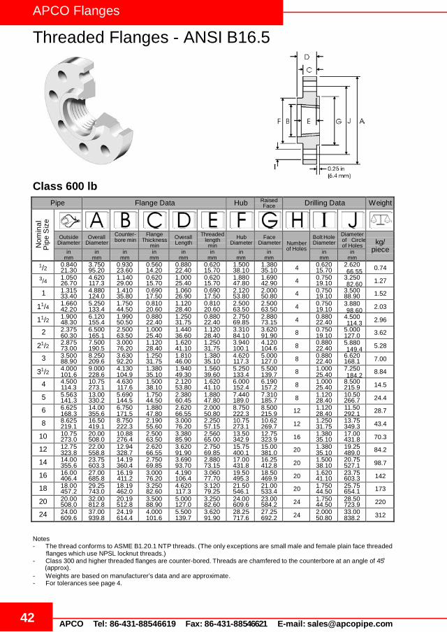
APCO Flanges
Threaded Flanges - ANSI B16.5
42 APCO Tel: 86-431-88546619 Fax: 86-431-88546621 E-mail: [email protected]
Pipe Flange Data Hub Raised Face Drilling Data Weight
Nom
inal
P
ipe
Siz
e
Outside Diameter
Overall Diameter
Counter- bore min
Flange Thickness
min Overall Length
Threaded length
min Hub
Diameter Face
Diameter
Number of Holes
Bolt Hole Diameter
Diameter of Circle of Holes
kg/
piece in mm
in mm
in mm
in mm
in mm
in mm
in mm
in mm
in mm
in mm
1/2 0.840 21.30
3.750 95.20
0.930 23.60
0.560 14.20
0.880 22.40
0.620 15.70
1.500 38.10
1.380 35.10 4 0.620
15.70 2.620 0.74
3/4 1.050 26.70
4.620 117.3
1.140 29.00
0.620 15.70
1.000 25.40
0.620 15.70
1.880 47.80
1.690 42.90 4 0.750
19.10 3.250 1.27
1 1.315 33.40
4.880 124.0
1.410 35.80
0.690 17.50
1.060 26.90
0.690 17.50
2.120 53.80
2.000 50.80 4 0.750
19.10 3.500 88.90 1.52
11/4 1.660 42.20
5.250 133.4
1.750 44.50
0.810 20.60
1.120 28.40
0.810 20.60
2.500 63.50
2.500 63.50 4 0.750
19.10 3.880 2.03
11/2 1.900 48.30
6.120 155.4
1.990 50.50
0.880 22.40
1.250 31.75
0.880 22.40
2.750 69.85
2.880 73.15 4 0.880
22.40 4.500 2.96
2 2.375 60.30
6.500 165.1
2.500 63.50
1.000 25.40
1.440 36.60
1.120 28.40
3.310 84.10
3.620 91.90 8 0.750
19.10 5.000 127.0 3.62
21/2 2.875 73.00
7.500 190.5
3.000 76.20
1.120 28.40
1.620 41.10
1.250 31.75
3.940 100.1
4.120 104.6 8 0.880
22.40 5.880 5.28
3 3.500 88.90
8.250 209.6
3.630 92.20
1.250 31.75
1.810 46.00
1.380 35.10
4.620 117.3
5.000 127.0 8 0.880
22.40 6.620 168.1 7.00
31/2 4.000 101.6
9.000 228.6
4.130 104.9
1.380 35.10
1.940 49.30
1.560 39.60
5.250 133.4
5.500 139.7 8 1.000
25.40 7.250 8.84
4 4.500 114.3
10.75 273.1
4.630 117.6
1.500 38.10
2.120 53.80
1.620 41.10
6.000 152.4
6.190 157.2 8 1.000
25.40 8.500 215.9 14.5
5 5.563 141.3
13.00 330.2
5.690 144.5
1.750 44.50
2.380 60.45
1.880 47.80
7.440 189.0
7.310 185.7 8 1.120
28.40 10.50 266.7 24.4
6 6.625 168.3
14.00 355.6
6.750 171.5
1.880 47.80
2.620 66.55
2.000 50.80
8.750 222.3
8.500 215.9 12 1.120
28.40 11.50 292.1 28.7
8 8.625 219.1
16.50 419.1
8.750 222.3
2.190 55.60
3.000 76.20
2.250 57.15
10.75 273.1
10.62 269.7 12 1.250
31.75 13.75 349.3 43.4
10 10.75 273.0
20.00 508.0
10.88 276.4
2.500 63.50
3.380 85.90
2.560 65.00
13.50 342.9
12.75 323.9 16 1.380
35.10 17.00 431.8 70.3
12 12.75 323.8
22.00 558.8
12.94 328.7
2.620 66.55
3.620 91.90
2.750 69.85
15.75 400.1
15.00 381.0 20 1.380
35.10 19.25 489.0 84.2
14 14.00 355.6
23.75 603.3
14.19 360.4
2.750 69.85
3.690 93.70
2.880 73.15
17.00 431.8
16.25 412.8 20 1.500
38.10 20.75 527.1 98.7
16 16.00 406.4
27.00 685.8
16.19 411.2
3.000 76.20
4.190 106.4
3.060 77.70
19.50 495.3
18.50 469.9 20 1.620
41.10 23.75 603.3 142
18 18.00 457.2
29.25 743.0
18.19 462.0
3.250 82.60
4.620 117.3
3.120 79.25
21.50 546.1
21.00 533.4 20 1.750
44.50 25.75 654.1 173
20 20.00 508.0
32.00 812.8
20.19 512.8
3.500 88.90
5.000 127.0
3.250 82.60
24.00 609.6
23.00 584.2 24 1.750
44.50 28.50 723.9 220
24 24.00 609.6
37.00 939.8
24.19 614.4
4.000 101.6
5.500 139.7
3.620 91.90
28.25 717.6
27.25 692.2 24 2.000
50.80 33.00 838.2 312
Class 600 lb
66.55
82.60
98.60
114.3
149.4
184.2
Notes - The thread conforms to ASME B1.20.1 NTP threads. (The only exceptions are small male and female plain face threaded
flanges which use NPSL locknut threads.) - Class 300 and higher threaded flanges are counter-bored. Threads are chamfered to the counterbore at an angle of 45°
(approx). - Weights are based on manufacturer’s data and are approximate. - For tolerances see page 4.

43 APCO Tel: 86-431-88546619 Fax: 86-431-88546621 E-mail: [email protected]
APCO Flanges
Threaded Flanges - ANSI B16.5
Pipe Flange Data Hub Raised Face Drilling Data Weight
Nom
inal
Outside Diameter
Diameter Overall
Counter- bore min
Flange Thickness
min Overall Length
Threaded length min Hub
Diameter Face
Diameter
Number of Holes
Bolt Hole Diameter
Diameter of Circle of Holes
kg/
piece in mm
in mm
in mm
in mm
in mm
in mm
in mm
in mm
in mm
in mm
1/2 0.840 21.30
4.750 120.6
0.930 23.60
0.880 22.30
1.250 31.70
0.880 22.30
1.500 38.10
1.380 35.10 4 0.880
22.30 3.250 1.74
3/4 1.050 26.70
5.120 130.0
1.140 29.00
1.000 25.40
1.380 35.00
1.000 25.40
1.750 44.40
1.690 42.90 4 0.880
22.30 3.500 2.34
1 1.315 33.40
5.880 149.3
1.410 35.80
1.120 28.40
1.620 41.10
1.120 28.40
2.060 52.30
2.000 50.80 4 1.000
25.40 4.000 101.6 3.44
11/4 1.660 42.20
6.250 158.7
1.750 44.40
1.120 28.40
1.620 41.10
1.190 30.20
2.500 63.50
2.500 63.50 4 1.000
25.40 4.380 3.91
11/2 1.900 48.30
7.000 177.8
1.990 50.50
1.250 31.70
1.750 44.50
1.250 31.70
2.750 69.85
2.880 73.15 4 1.120
28.40 4.880 5.36
2 2.375 60.30
8.500 215.9
2.500 63.50
1.500 38.10
2.250 57.15
1.500 38.10
4.120 104.6
3.620 91.90 8 1.000
25.40 6.500 165.1 9.85
21/2 2.875 73.00
9.620 244.3
3.000 76.20
1.620 41.10
2.500 63.50
1.880 47.70
4.880 123.9
4.120 104.6 8 1.120
28.40 7.500 13.7
3 3.500 88.90
9.500 241.3
3.630 92.20
1.500 38.10
2.120 53.80
1.620 41.10
5.000 127.0
5.000 127.0 8 1.000
25.40 7.500 190.5 11.6
4 4.500 114.3
11.50 292.1
4.630 117.6
1.750 44.40
2.750 69.85
1.880 47.80
6.250 158.7
6.190 157.2 8 1.250
31.70 9.250 234.9 19.7
5 5.563 141.3
13.75 349.2
5.690 144.5
2.000 50.80
3.120 79.25
2.120 53.80
7.500 190.5
7.310 185.7 8 1.380
35.00 11.00 279.4 31.9
6 6.625 168.3
15.00 381.0
6.750 171.4
2.190 55.60
3.380 85.80
2.250 57.15
9.250 234.9
8.500 215.9 12 1.250
31.70 12.50 317.5 41.1
8 8.625 219.1
18.50 469.9
8.750 222.2
2.500 63.50
4.000 101.6
2.500 63.50
11.75 298.4
10.62 269.7 12 1.500
38.10 15.50 393.7 70.7
10 10.75 273.0
21.50 546.1
10.88 276.3
2.750 69.85
4.250 107.9
2.810 71.40
14.50 368.3
12.75 323.9 16 1.500
38.10 18.50 469.9 101
12 12.75 323.8
24.00 609.6
12.94 328.7
3.120 79.40
4.620 117.3
3.000 76.20
16.50 419.1
15.00 381.0 20 1.500
38.10 21.00 533.4 133
14 14.00 355.6
25.25 641.3
14.19 360.4
3.380 85.70
5.120 130.0
3.250 82.50
17.75 450.8
16.25 412.7 20 1.620
41.10 22.00 558.8 153
16 16.00 406.4
27.75 704.8
16.19 411.2
3.500 88.90
5.250 133.3
3.380 85.90
20.00 508.0
18.50 469.9 20 1.750
44.40 24.25 618.9 185
18 18.00 457.2
31.00 787.4
18.19 462.0
4.000 101.6
6.000 152.4
3.500 88.90
22.25 565.1
21.00 533.4 20 2.000
50.80 27.00 685.8 258
20 20.00 508.0
33.75 857.2
20.19 512.8
4.250 107.9
6.250 158.7
3.620 91.90
24.50 622.3
23.00 584.2 20 2.120
53.80 29.50 749.3 317
24 24.00 609.6
41.00 1041.4
24.19 614.4
5.500 139.7
8.000 203.2
4.000 101.6
29.50 749.3
27.25 692.2 20 2.620
66.55 35.50 901.7 606
Pip
e S
ize
Class 900 lb
82.50
88.90
111.2
123.9
190.5
Notes - The thread conforms to ASME B1.20.1 NTP threads. (The only exceptions are small male and female plain face threaded
flanges which use NPSL locknut threads.) - Class 300 and higher threaded flanges are counter-bored. Threads are chamfered to the counterbore at an angle of 45°
(approx). - Weights are based on manufacturer’s data and are approximate. - For tolerances see page 4.

APCO Flanges
Threaded Flanges - ANSI B16.5
44 APCO Tel: 86-431-88546619 Fax: 86-431-88546621 E-mail: [email protected]
Pipe Flange Data Hub Raised Face Drilling Data Weight
Nom
inal
P
ipe
Siz
e
Outside Diameter
Overall Diameter
Counter- bore min
Flange Thickness
min Overall Length
Threaded length min Hub
Diameter Face
Diameter
Number of Holes
Bolt Hole Diameter
Diameter of Circle of Holes
kg/
piece in mm
in mm
in mm
in mm
in mm
in mm
in mm
in mm
in mm
in mm
1/2 0.840 21.30
4.750 120.6
0.930 23.60
0.880 22.30
1.250 31.70
0.880 22.30
1.500 38.10
1.380 35.00 4 0.880
22.30 3.250 1.74
3/4 1.050 26.70
5.120 130.0
1.140 29.00
1.000 25.40
1.380 35.00
1.000 25.40
1.750 44.40
1.690 42.90 4 0.880
22.30 3.500 2.34
1 1.315 33.40
5.880 149.3
1.410 35.80
1.120 28.40
1.620 41.10
1.120 28.40
2.060 52.30
2.000 50.80 4 1.000
25.40 4.000 101.6 3.44
11/4 1.660 42.20
6.250 158.7
1.750 44.40
1.120 28.40
1.620 41.10
1.190 30.20
2.500 63.50
2.500 63.50 4 1.000
25.40 4.380 3.91
11/2 1.900 48.30
7.000 177.8
1.990 50.50
1.250 31.70
1.750 44.50
1.250 31.70
2.750 69.85
2.880 73.15 4 1.120
28.40 4.880 5.36
2 2.375 60.30
8.500 215.9
2.500 63.50
1.500 38.10
2.250 57.15
1.500 38.10
4.120 104.6
3.620 91.90 8 1.000
25.40 6.500 165.1 9.85
21/2 2.875 73.00
9.620 244.3
3.000 76.20
1.620 41.10
2.500 63.50
1.880 47.70
4.880 123.9
4.120 104.6 8 1.120
28.40 7.500 13.7
Class 1500 lb
82.50
88.90
111.2
123.9
190.5
Notes - The thread conforms to ASME B1.20.1 NTP threads. (The only exceptions are small male and female plain face threaded
flanges which use NPSL locknut threads.) - Class 300 and higher threaded flanges are counter-bored. Threads are chamfered to the counterbore at an angle of 45°
(approx). - Weights are based on manufacturer’s data and are approximate. - For tolerances see page 4.

45 APCO Tel: 86-431-88546619 Fax: 86-431-88546621 E-mail: [email protected]
APCO Flanges
Threaded Flanges - ANSI B16.5
Pipe Flange Data Hub Raised Face Drilling Data Weight
Nom
inal
Outside Diameter
Overall Diameter
Counter- bore min
Flange Thickness
min Overall Length
Threaded length min Hub
Diameter Face
Diameter
Number of Holes
Bolt Hole Diameter
Diameter of Circle of Holes
kg/
piece in mm
in mm
in mm
in mm
in mm
in mm
in mm
in mm
in mm
in mm
1/2 0.840 21.30
5.250 133.4
0.930 23.60
1.190 30.20
1.560 39.60
1.120 28.40
1.690 42.90
1.380 35.10 4 0.880
22.40 3.500 2.95
3/4 1.050 26.70
5.500 139.7
1.140 29.00
1.250 31.75
1.690 42.90
1.250 31.75
2.000 50.80
1.690 42.90 4 0.880
22.40 3.750 3.44
1 1.315 33.40
6.250 158.8
1.410 35.80
1.380 35.10
1.880 47.80
1.380 35.10
2.250 57.15
2.000 50.80 4 1.000
25.40 4.250 108.0 4.82
11/4 1.660 42.20
7.250 1.842
1.750 44.50
1.500 38.10
2.060 52.30
1.500 38.10
2.880 73.15
2.500 63.50 4 1.120
28.40 5.120 7.14
11/2 1.900 48.30
8.000 203.2
1.990 50.50
1.750 44.50
2.380 60.45
1.750 44.50
3.120 79.25
2.880 73.15 4 1.250
31.75 5.750 10.0
2 2.375 60.30
9.250 235.0
2.500 63.50
2.000 50.80
2.750 69.85
2.000 50.80
3.750 95.30
3.620 91.90 8 1.120
28.40 6.750 171.5 14.8
21/2 2.875 73.00
10.50 266.7
3.000 76.20
2.250 57.15
3.120 79.25
2.250 57.15
4.500 114.3
4.120 104.6 8 1.250
31.75 7.750 21.5
Pip
e S
ize
Class 2500 lb
88.90
95.30
130.0
146.1
196.9
Notes - The thread conforms to ASME B1.20.1 NTP threads. (The only exceptions are small male and female plain face threaded
flanges which use NPSL locknut threads.) - Class 300 and higher threaded flanges are counter-bored. Threads are chamfered to the counterbore at an angle of 45°
(approx). - Weights are based on manufacturer’s data and are approximate. - For tolerances see page 4.

APCO Flanges
ASME B16.47 Series A (MSS SP-44) Flanges
46 APCO Tel: 86-431-88546619 Fax: 86-431-88546621 E-mail: [email protected]
Class 150 lbPipe Flange Data Hub Data Raised
Face Drilling Data Radius
Nom
inal
Pip
eS
ize
Overall
Diameter
WNFFlange
Thickness min
BlindFlange
Thickness min
Overall Length WNF
Diameterat Weld Bevel
Hub
Diameter
Face
Diameter
Number of Holes
Bolt HoleDiameter
Diameter of Circle of Holes
Fillet
in mm
in mm
in mm
in mm
in mm
in mm
in mm
in mm
in mm
in mm
22 29.50749.30
1.8145.97
1.8145.97
5.88149.35
22.00558.80
24.00609.60
25.25641.35 20 1.38
35.0527.25692.15
0.389.65
26 34.25869.95
2.6968.33
2.6968.33
4.75120.65
26.00660.40
26.62676.15
29.50749.30 24 1.38
35.0531.75806.45
0.389.65
28 36.50927.10
2.8171.37
2.8171.37
4.94125.48
28.00711.20
28.62726.95
31.50800.10 28 1.38
35.0534.00863.60
0.4411.18
30 38.75984.25
2.9474.68
2.9474.68
5.38136.65
30.00762.00
30.75781.05
33.75857.25 28 1.38
35.0536.00914.40
0.4411.18
32 41.751060.5
3.1981.03
3.1981.03
5.69144.53
32.00812.80
32.75831.85
36.00914.40 28 1.62
41.1538.50977.90
0.4411.18
34 43.751111.3
3.2582.55
3.2582.55
5.88149.35
34.00863.60
34.75882.65
38.00965.20 32 1.62
41.1540.501028.7
0.5012.70
36 46.001168.4
3.5690.42
3.5690.42
6.19157.23
36.00914.40
36.75933.45
40.251022.4 32 1.62
41.1542.751085.9
0.5012.70
38 48.751238.3
3.4487.38
3.4487.38
6.19157.23
38.00965.20
39.00990.60
42.251073.2 32 1.62
41.1545.251149.4
0.5012.70
40 50.751289.1
3.5690.42
3.5690.42
6.44163.58
40.001016.0
41.001041.4
44.251124.0 36 1.62
41.1547.251200.2
0.5012.70
42 53.001346.2
3.8196.77
3.8196.77
6.75171.45
42.001066.8
43.001092.2
47.001193.8 36 1.62
41.1549.501257.3
0.5012.70
44 55.251403.4
4.00101.60
4.00101.60
7.00177.80
44.001117.6
45.001143.0
49.001244.6 40 1.62
41.1551.751314.5
0.5012.70
46 57.251454.2
4.06103.12
4.06103.12
7.31185.67
46.001168.4
47.121196.9
51.001295.4 40 1.62
41.1553.751365.3
0.5012.70
48 59.501511.3
4.25107.95
4.25107.95
7.56192.02
48.001219.2
49.121247.7
53.501358.9 44 1.62
41.1556.001422.4
0.5012.70
Notes- ASME B16.47 Series A flanges (> NPS 26) are MMS SP-44 flanges. MSS SP-44 also covers NPS 12 to NPS 24 flanges
which are equivalent to ASME B16.5. MSS SP-44 is the only source for the NPS 22 flange dimensions above.- Dimension B is to be specified by the purchaser. It corresponds to the pipe inside diameter.- Flat face flanges may be provided at full thickness, C, or with raised face removed (the latter is nonstandard).- WNF = Weld Neck Flange.- The large end of the hub may be straight or tapered.- For ring joint facings see page 6. For weld end bevel see page 5.- For tolerances see page 4.

47APCO Tel: 86-431-88546619 Fax: 86-431-88546621 E-mail: [email protected]
APCO Flanges
ASME B16.47 Series A (MSS SP-44) Flanges
Class 300 lbPipe Flange Data Hub Data Raised
Face Drilling Data Radius
Nom
inal
Pip
eS
ize
Overall
Diameter
WNF Flange
Thickness min
Blind Flange
Thickness min
Overall LengthWNF
Diameter at Weld Bevel
Hub
Diameter
Face
Diameter
Number of Holes
Bolt HoleDiameter
Diameter of Circle of Holes
Fillet
in mm
in mm
in mm
in mm
in mm
in mm
in mm
in mm
in mm
in mm
22 33.00838.20
2.6266.55
2.6266.55
6.50165.10
22.00558.80
25.25641.35
25.25641.35 24 1.62
41.1529.25742.95
0.389.65
26 38.25971.55
3.1279.25
3.3184.07
7.25184.15
26.00660.40
28.38720.85
29.50749.30 28 1.75
44.4534.50876.30
0.389.65
28 40.751035.1
3.3885.85
3.5690.42
7.75196.85
28.00711.20
30.50774.70
31.50800.10 28 1.75
44.4537.00939.80
0.4411.18
30 43.001092.2
3.6291.95
3.7595.25
8.25209.55
30.00762.00
32.56827.02
33.75857.25 28 1.88
47.7539.25996.95
0.4411.18
32 45.251149.4
3.8898.55
3.94100.08
8.75222.25
32.00812.80
34.69881.13
36.00914.40 28 2.00
50.8041.501054.1
0.4411.18
34 47.50120.50
4.00101.60
4.12104.65
9.12231.65
34.00863.60
36.88936.75
38.00965.20 28 2.00
50.8043.501104.9
0.5012.70
36 50.001270.0
4.12104.65
4.38111.25
9.50241.30
36.00914.40
39.00990.60
40.251022.4 32 2.12
53.8546.001168.4
0.5012.70
38 46.001168.4
4.25107.95
4.25107.95
7.12180.85
38.00965.20
39.12993.65
40.501028.7 32 1.62
41.1543.001092.2
0.5012.70
40 48.751238.3
4.50114.30
4.50114.30
7.62193.55
40.001016.0
41.251047.8
42.751085.9 32 1.75
44.4545.501155.7
0.5012.70
42 50.751289.1
4.69119.13
4.69119.13
7.88200.15
42.001066.8
43.251098.6
44.751136.7 32 1.75
44.4547.501206.6
0.5012.70
44 53.251352.6
4.88123.95
4.88123.95
8.12206.25
44.001117.6
45.251149.4
47.001193.8 32 1.88
47.7549.751263.7
0.5012.70
46 55.751416.1
5.06128.52
5.06128.52
8.50215.90
46.001168.4
47.381203.5
49.001244.0 28 2.00
50.8052.001320.8
0.5012.70
48 57.751466.9
5.25133.35
5.25133.35
8.81223.77
48.001219.2
49.381254.3
51.251301.8 32 2.00
50.8054.001371.6
0.5012.70
Notes- ASME B16.47 Series A flanges (> NPS 26) are MMS SP-44 flanges. MSS SP-44 also covers NPS 12 to NPS 24 flanges
which are equivalent to ASME B16.5. MSS SP-44 is the only source for the NPS 22 flange dimensions above.- Dimension B is to be specified by the purchaser. It corresponds to the pipe inside diameter.- Flat face flanges may be provided at full thickness, C, or with raised face removed (the latter is nonstandard).- WNF = Weld Neck Flange.- The large end of the hub may be straight or tapered.- For ring joint facings see page 6. For weld end bevel see page 5.- For tolerances see page 4.

APCO Flanges
ASME B16.47 Series A (MSS SP-44) Flanges
48 APCO Tel: 86-431-88546619 Fax: 86-431-88546621 E-mail: [email protected]
Pip
eS
ize
Class 400 lbPipe Flange Data Hub Data Raised
Face Drilling Data Radius
Nom
inal
Overall
Diameter
WNF Flange
Thickness min
Blind Flange
Thickness min
OverallLength WNF
Diameter at Weld Bevel
Hub
Diameter
Face
Diameter
Number of Holes
Bolt HoleDiameter
Diameter of Circle of Holes
Fillet
in mm
in mm
in mm
in mm
in mm
in mm
in mm
in mm
in mm
in mm
22 33.00838.20
2.8873.15
2.8873.15
6.75171.45
22.00558.80
25.25641.35
25.25641.35 24 1.75
44.4529.25742.95
0.4411.18
26 38.25971.55
3.5088.90
3.8898.55
7.62193.55
26.00660.40
28.62726.95
29.50749.30 28 1.88
47.7534.50876.30
0.4411.18
28 40.751035.1
3.7595.25
4.12104.65
8.12206.25
28.00711.20
30.81782.57
31.50800.10 28 2.00
50.8037.00939.80
0.5012.70
30 43.001092.2
4.00101.60
4.38111.25
8.62218.95
30.00762.00
32.94836.68
33.75857.25 28 2.12
53.8539.25996.95
0.5012.70
32 45.251149.4
4.25107.95
4.56115.82
9.12231.65
32.00812.80
35.00889.00
36.00914.40 28 2.12
53.8541.501054.1
0.5012.70
34 47.501206.5
4.38111.25
4.81122.17
9.50241.30
34.00863.60
37.19944.63
38.00965.20 28 2.12
53.8543.501104.9
0.5614.22
36 50.001270.0
4.50114.30
5.06128.52
9.88250.95
36.00914.40
39.381000.3
40.251022.4 32 2.12
53.8546.001168.4
0.5614.22
38 47.501206.5
4.88123.95
4.88123.95
8.12206.25
48.001219.2
39.501003.3
40.751035.1 32 1.88
47.7544.001117.6
0.5614.22
40 50.001270.0
5.12130.05
5.12130.05
8.50215.90
40.001016.0
41.501054.1
43.001092.2 32 2.00
50.8046.251174.8
0.5614.22
42 52.001320.8
5.25133.35
5.25133.35
8.81223.77
42.001066.8
43.621107.9
45.001143.0 32 2.00
50.8048.251225.6
0.5614.22
44 54.501384.3
5.50139.70
5.50139.70
9.18233.17
44.001117.6
45.621158.7
47.251200.2 32 2.12
53.8550.501282.7
0.5614.22
46 56.751441.5
5.75146.05
5.75146.05
9.62244.35
46.001168.4
47.751212.9
49.501257.3 36 2.12
53.8552.751339.9
0.5614.22
48 59.501511.3
6.00152.40
6.00152.40
10.12257.05
48.001219.2
49.881267.0
51.501308.1 28 2.38
60.4555.251403.4
0.5614.22
Notes- ASME B16.47 Series A flanges (> NPS 26) are MMS SP-44 flanges. MSS SP-44 also covers NPS 12 to NPS 24 flanges
which are equivalent to ASME B16.5. MSS SP-44 is the only source for the NPS 22 flange dimensions above.- Class 400 Series A dimensions at NPS 38 and larger also apply to Class 400 Series B flanges.- Dimension B is to be specified by the purchaser. It corresponds to the pipe inside diameter.- Flat face flanges may be provided at full thickness, C + raised face, or with raised face removed (the latter is nonstandard).- WNF = Weld Neck Flange.- The large end of the hub may be straight or tapered.- For ring joint facings see page 6. For weld end bevel see page 5.- For tolerances see page 4.
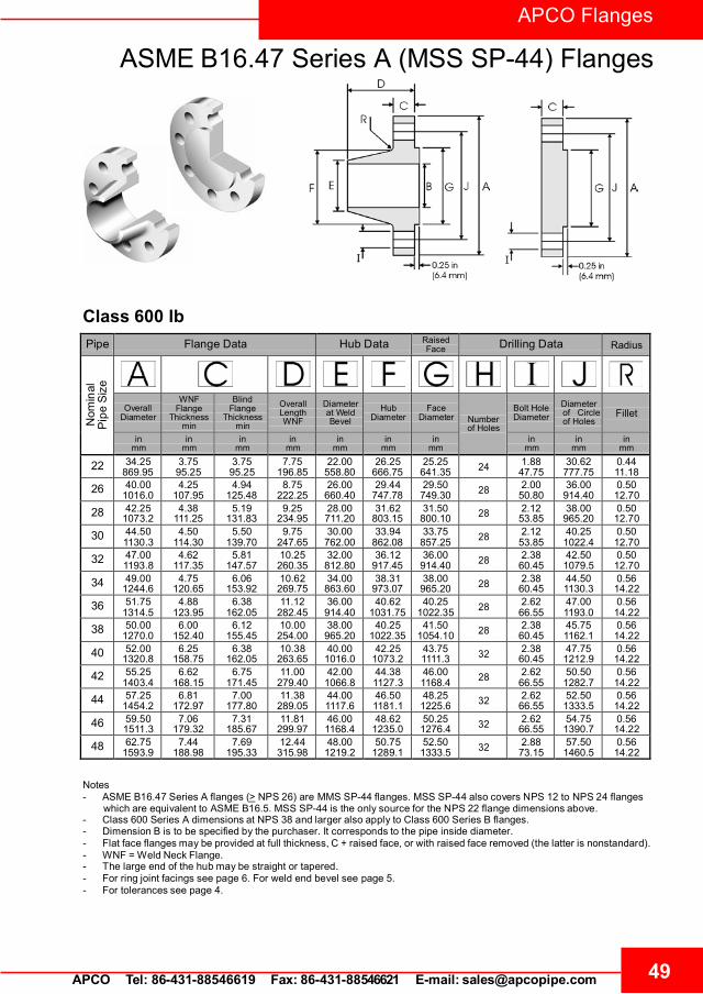
49APCO Tel: 86-431-88546619 Fax: 86-431-88546621 E-mail: [email protected]
APCO Flanges
ASME B16.47 Series A (MSS SP-44) Flanges
Class 600 lbPipe Flange Data Hub Data Raised
Face Drilling Data Radius
Nom
inal
Pip
eS
ize
OverallDiameter
WNFFlange
Thickness min
Blind Flange
Thickness min
Overall Length WNF
Diameter at Weld Bevel
Hub
Diameter
Face
Diameter
Number of Holes
Bolt HoleDiameter
Diameter of Circle of Holes
Fillet
in mm
in mm
in mm
in mm
in mm
in mm
in mm
in mm
in mm
in mm
22 34.25869.95
3.7595.25
3.7595.25
7.75196.85
22.00558.80
26.25666.75
25.25641.35 24 1.88
47.7530.62777.75
0.4411.18
26 40.001016.0
4.25107.95
4.94125.48
8.75222.25
26.00660.40
29.44747.78
29.50749.30 28 2.00
50.8036.00914.40
0.5012.70
28 42.251073.2
4.38111.25
5.19131.83
9.25234.95
28.00711.20
31.62803.15
31.50800.10 28 2.12
53.8538.00965.20
0.5012.70
30 44.501130.3
4.50114.30
5.50139.70
9.75247.65
30.00762.00
33.94862.08
33.75857.25 28 2.12
53.8540.251022.4
0.5012.70
32 47.001193.8
4.62117.35
5.81147.57
10.25260.35
32.00812.80
36.12917.45
36.00914.40 28 2.38
60.4542.501079.5
0.5012.70
34 49.001244.6
4.75120.65
6.06153.92
10.62269.75
34.00863.60
38.31973.07
38.00965.20 28 2.38
60.4544.501130.3
0.5614.22
36 51.751314.5
4.88123.95
6.38162.05
11.12282.45
36.00914.40
40.621031.75
40.251022.35 28 2.62
66.5547.001193.0
0.5614.22
38 50.001270.0
6.00152.40
6.12155.45
10.00254.00
38.00965.20
40.251022.35
41.501054.10 28 2.38
60.4545.751162.1
0.5614.22
40 52.001320.8
6.25158.75
6.38162.05
10.38263.65
40.001016.0
42.251073.2
43.751111.3 32 2.38
60.4547.751212.9
0.5614.22
42 55.251403.4
6.62168.15
6.75171.45
11.00279.40
42.001066.8
44.381127.3
46.001168.4 28 2.62
66.5550.501282.7
0.5614.22
44 57.251454.2
6.81172.97
7.00177.80
11.38289.05
44.001117.6
46.501181.1
48.251225.6 32 2.62
66.5552.501333.5
0.5614.22
46 59.501511.3
7.06179.32
7.31185.67
11.81299.97
46.001168.4
48.621235.0
50.251276.4 32 2.62
66.5554.751390.7
0.5614.22
48 62.751593.9
7.44188.98
7.69195.33
12.44315.98
48.001219.2
50.751289.1
52.501333.5 32 2.88
73.1557.501460.5
0.5614.22
Notes- ASME B16.47 Series A flanges (> NPS 26) are MMS SP-44 flanges. MSS SP-44 also covers NPS 12 to NPS 24 flanges
which are equivalent to ASME B16.5. MSS SP-44 is the only source for the NPS 22 flange dimensions above.- Class 600 Series A dimensions at NPS 38 and larger also apply to Class 600 Series B flanges.- Dimension B is to be specified by the purchaser. It corresponds to the pipe inside diameter.- Flat face flanges may be provided at full thickness, C + raised face, or with raised face removed (the latter is nonstandard).- WNF = Weld Neck Flange.- The large end of the hub may be straight or tapered.- For ring joint facings see page 6. For weld end bevel see page 5.- For tolerances see page 4.

APCO Flanges
ASME B16.47 Series A (MSS SP-44) Flanges
50 APCO Tel: 86-431-88546619 Fax: 86-431-88546621 E-mail: [email protected]
Pip
eS
ize
Class 900 lbPipe Flange Data Hub Data Raised
Face Drilling Data Radius
Nom
inal
Overall
Diameter
WNFFlange
Thickness min
Blind Flange
Thickness min
Overall Length WNF
Diameterat Weld Bevel
HubDiameter
Face
Diameter
Number of Holes
Bolt HoleDiameter
Diameter of Circleof Holes
Fillet
in mm
in mm
in mm
in mm
in mm
in mm
in mm
in mm
in mm
in mm
26 42.751085.9
5.50139.70
6.31160.27
11.25285.75
26.00660.40
30.50774.70
29.50749.30 20 2.88
73.1537.50952.50
0.4411.18
28 46.001168.4
5.62142.75
6.75171.45
11.75298.45
28.00711.20
32.75831.85
31.50800.10 20 3.12
79.2540.251022.4
0.5012.70
30 48.501231.9
5.88149.35
7.18182.37
12.25311.15
30.00762.00
35.00889.00
33.75857.25 20 3.12
79.2542.751085.9
0.5012.70
32 51.751314.5
6.25158.75
7.62193.55
13.00330.20
32.00812.80
37.25946.15
36.00914.40 20 3.38
85.8545.501155.7
0.5012.70
34 55.001397.0
6.50165.10
8.06204.72
13.75349.25
34.00863.60
39.621006.4
38.00965.20 20 3.62
91.9548.251225.6
0.5614.22
36 57.501460.5
6.75171.45
8.44214.38
14.25361.95
36.00914.40
41.881063.8
40.251022.4 20 3.62
91.9550.751289.1
0.5614.22
38 57.501460.5
7.50190.50
8.50215.90
13.88352.55
38.00965.20
42.251073.2
43.251098.6 20 3.62
91.9550.751289.1
0.7519.05
40 59.501511.3
7.75196.85
8.81223.77
14.31363.47
40.001016.0
44.381127.3
45.751162.1 24 3.62
91.9552.751339.9
0.8120.57
42 61.501562.1
8.12206.25
9.12231.65
14.62371.35
42.001066.8
46.311176.3
47.751212.9 24 3.62
91.9554.751390.7
0.8120.57
44 64.881648.0
8.44214.38
9.56242.82
15.38390.65
44.001117.6
48.621235.0
50.001270.0 24 3.88
98.5557.621463.6
0.8822.35
46 68.251733.6
8.88225.55
10.06255.52
16.18410.97
46.001168.4
50.881292.4
52.501333.5 24 4.12
104.6560.501536.7
0.8822.35
48 70.251784.4
9.19233.43
10.38263.65
16.50419.10
48.001219.2
52.881343.2
54.501384.3 24 4.12
104.6562.501587.5
0.9423.88
Notes- ASME B16.47 Series A flanges (> NPS 26) are MMS SP-44 flanges. MSS SP-44 also covers NPS 12 to NPS 24 flanges
which are equivalent to ASME B16.5. MSS SP-44 is the only source for the NPS 22 flange dimensions above.- Class 900 Series A dimensions at NPS 38 and larger also apply to Class 900 Series B flanges.- Dimension B is to be specified by the purchaser. It corresponds to the pipe inside diameter.- Flat face flanges may be provided at full thickness, C + raised face, or with raised face removed (the latter is nonstandard).- WNF = Weld Neck Flange.- The large end of the hub may be straight or tapered.- For ring joint facings see page 6. For weld end bevel see page 5.- For tolerances see page 4.

51APCO Tel: 86-431-88546619 Fax: 86-431-88546621 E-mail: [email protected]
APCO Flanges
ASME B16.47 Series B (API 605) Flanges
Class 75 lbPipe Flange Data Hub Data Raised
Face Drilling Data Radius
Nom
inal
Pip
eS
ize
OverallDiameter
WNF Flange
Thickness min
Blind Flange
Thickness min
Overall Length WNF
Diameterat Weld Bevel
Hub
Diameter
Face
Diameter
Number ofHoles
Bolt HoleDiameter
Diameterof Circle of
Holes
Fillet
in mm
in mm
in mm
in mm
in mm
in mm
in mm
in mm
in mm
in mm
26 30.00762.00
1.3133.27
1.3133.27
2.3158.67
26.06661.92
26.62676.15
27.75704.85 36 0.75
19.0528.50723.90
0.317.87
28 32.00812.80
1.3133.27
1.3133.27
2.4461.98
28.06712.72
28.62726.95
29.75755.65 40 0.75
19.0530.50774.70
0.317.87
30 34.00863.60
1.3133.27
1.3133.27
2.5665.02
30.06763.52
30.62777.75
31.75806.45 44 0.75
19.0532.50825.50
0.317.87
32 36.00914.40
1.3835.05
1.4436.58
2.7569.85
32.06814.32
32.62828.55
33.75857.25 48 0.75
19.0534.50876.30
0.317.87
34 38.00965.20
1.3835.05
1.5038.10
2.8873.15
34.06865.12
34.62879.35
35.75908.05 52 0.75
19.0536.50927.10
0.317.87
36 40.691033.5
1.4436.58
1.6742.42
3.3885.85
36.06915.92
36.81934.97
38.00965.20 40 0.88
22.3539.06992.12
0.389.65
38 42.691084.3
1.5038.10
1.7544.45
3.5088.90
38.06966.72
38.81985.77
40.001016.0 40 0.88
22.3541.061042.9
0.389.65
40 44.691135.1
1.5038.10
1.7544.45
3.6291.95
40.061017.5
40.811036.57
42.001066.8 44 0.88
22.3543.061093.7
0.389.65
42 46.691185.9
1.5639.62
1.8847.75
3.7595.25
42.061068.3
42.811087.37
44.001117.6 48 0.88
22.3545.061144.5
0.389.65
44 49.251251.0
1.6942.93
1.9449.28
4.12104.65
44.061119.1
44.881139.95
46.251174.8 36 1.00
25.4047.381203.5
0.389.65
46 51.251301.8
1.7544.45
2.0050.80
4.25107.95
46.061169.9
46.881190.75
48.251225.6 40 1.00
25.4049.381254.3
0.389.65
48 53.251352.6
1.8145.97
2.1253.85
4.38111.25
48.061220.7
48.881241.55
50.251276.4 44 1.00
25.4051.381305.1
0.389.65
Notes- ASME B16.47 Series B flanges are API 605 flanges. API 605 has been cancelled.- Class 400 Series A dimensions at NPS 38 and larger also apply to Class 400 Series B flanges.- Dimension B is to be specified by the purchaser. It corresponds to the pipe inside diameter.- Flat face flanges may be provided at full thickness, C, or with raised face removed (the latter is nonstandard).- WNF = Weld Neck Flange.- The large end of the hub may be straight or tapered.- For ring joint facings see page 6. For weld end bevel see page 5.- For tolerances see page 4.

APCO Flanges
ASME B16.47 Series B (API 605) Flanges
52 APCO Tel: 86-431-88546619 Fax: 86-431-88546621 E-mail: [email protected]
Class 150 lbPipe Flange Data Hub Data Raised
Face Drilling Data Radius
Nom
inal
Pip
eS
ize
Overall
Diameter
WNF Flange
Thickness min
BlindFlange
Thickness min
Overall LengthWNF
Diameter at Weld Bevel
Hub
Diameter
Face
Diameter
Number ofHoles
Bolt HoleDiameter
Diameter of Circle of
Holes
Fillet
in mm
in mm
in mm
in mm
in mm
in mm
in mm
in mm
in mm
in mm
26 30.94785.88
1.6241.15
1.7544.45
3.5088.90
26.06661.92
26.94684.28
28.00711.20 36 0.88
22.3529.31744.47
0.389.65
28 32.94836.68
1.7544.45
1.8847.75
3.7595.25
28.06712.72
28.94735.08
30.00762.00 40 0.88
22.3531.31795.27
0.389.65
30 34.94887.48
1.7544.45
2.0050.80
3.94100.08
30.06763.52
31.00787.40
32.00812.80 44 0.88
22.3533.31846.07
0.389.65
32 37.06941.32
1.8145.97
2.1253.85
4.25107.95
32.06814.32
33.06839.72
34.00863.60 48 0.88
22.3535.44900.18
0.389.65
34 39.561004.8
1.9449.28
2.2557.15
4.34110.24
34.06865.12
35.12892.05
36.25920.75 40 1.00
25.4037.69957.33
0.389.65
36 41.621057.1
2.0652.32
2.3158.67
4.62117.35
36.06915.92
37.19944.63
38.25971.55 44 1.00
25.4039.751009.7
0.389.65
38 44.251124.0
2.1253.85
2.5063.50
4.88123.95
38.12968.25
39.25996.95
40.251022.4 40 1.12
28.4542.121069.8
0.389.65
40 46.251174.8
2.1955.63
2.6266.55
5.06128.52
40.121019.0
41.311049.3
42.501079.5 44 1.12
28.4544.121120.6
0.389.65
42 48.251225.6
2.3158.67
2.6968.33
5.25133.35
42.121069.8
43.381101.9
44.501130.3 48 1.12
28.4546.121171.4
0.4411.18
44 50.251276.4
2.3860.45
2.8171.37
5.38136.65
44.121120.6
45.381152.7
46.501181.1 52 1.12
28.4548.121222.2
0.4411.18
46 52.811341.4
2.4461.98
2.9474.68
5.69144.53
46.121171.4
47.441205.0
48.621234.9 40 1.25
31.7550.561284.2
0.4411.18
48 54.811392.2
2.5665.02
3.0677.72
5.88149.35
48.121222.2
49.501257.3
50.751289.1 44 1.25
31.7552.561335.0
0.4411.18
Notes- ASME B16.47 Series B flanges are API 605 flanges. API 605 has been cancelled.- Dimension B is to be specified by the purchaser. It corresponds to the pipe inside diameter.- Flat face flanges may be provided at full thickness, C, or with raised face removed (the latter is nonstandard).- WNF = Weld Neck Flange.- The large end of the hub may be straight or tapered.- For ring joint facings see page 6. For weld end bevel see page 5.- For tolerances see page 4.

53APCO Tel: 86-431-88546619 Fax: 86-431-88546621 E-mail: [email protected]
APCO Flanges
ASME B16.47 Series B (API 605) Flanges
Class 300 lbPipe Flange Data Hub Data Raised
Face Drilling Data Radius
Nom
inal
Pip
eS
ize
Overall
Diameter
WNF Flange
Thickness min
Blind Flange
Thickness min
OverallLength WNF
Diameter at Weld Bevel
Hub
Diameter
Face
Diameter Number of
Holes
Bolt HoleDiameter
Diameter of Circle of Holes
Fillet
in mm
in mm
in mm
in mm
in mm
in mm
in mm
in mm
in mm
in mm
26 34.12866.65
3.5088.90
3.5088.90
5.69144.53
26.19665.23
27.62701.55
29.00736.60 32 1.38
35.0531.62803.15
0.5614.22
28 36.25920.75
3.5088.90
3.5088.90
5.88149.35
28.19716.03
29.75755.65
31.00787.40 36 1.38
35.0533.75857.25
0.5614.22
30 39.00990.60
3.6993.73
3.6993.73
6.22157.99
30.25768.35
32.00812.80
33.25844.55 36 1.50
38.1036.25920.75
0.5614.22
32 41.501054.1
4.06103.12
4.06103.12
6.62168.15
32.25819.15
34.00863.60
35.50901.70 32 1.62
41.1538.50977.90
0.6215.75
34 43.621107.9
4.06103.12
4.06103.12
6.81172.97
34.25869.95
36.12917.45
37.50952.50 36 1.62
41.1540.621031.7
0.6215.75
36 46.121171.4
4.06103.12
4.06103.12
7.12180.85
36.25920.75
38.00965.20
39.751009.7 32 1.75
44.4542.881089.2
0.6215.75
38 48.121222.2
4.38111.25
4.38111.25
7.56192.02
38.25971.55
40.001016.0
41.751060.5 36 1.75
44.4544.881140.0
0.6215.75
40 50.121273.0
4.56115.82
4.56115.82
7.81198.37
40.251022.4
42.001066.8
43.881114.6 40 1.75
44.4546.881190.8
0.6215.75
42 52.501333.5
4.69119.13
4.69119.13
8.06204.72
42.311074.7
44.001117.6
46.001168.4 36 1.88
47.7549.001244.6
0.6215.75
44 54.501384.3
5.00127.00
5.00127.00
8.44214.38
44.311125.5
46.191173.2
48.001219.2 40 1.88
47.7551.001295.4
0.6215.75
46 57.501460.5
5.06128.52
5.12130.05
8.75222.25
46.311176.3
48.381228.9
50.001270.0 36 2.00
50.8053.751365.3
0.6215.75
48 59.501511.3
5.06128.52
5.31134.87
8.81223.77
48.311227.1
50.311277.9
52.251327.2 40 2.00
50.8055.751416.1
0.6215.75
Notes- ASME B16.47 Series B flanges are API 605 flanges. API 605 has been cancelled.- Dimension B is to be specified by the purchaser. It corresponds to the pipe inside diameter.- Flat face flanges may be provided at full thickness, C, or with raised face removed (the latter is nonstandard).- WNF = Weld Neck Flange.- The large end of the hub may be straight or tapered.- For ring joint facings see page 6. For weld end bevel see page 5.- For tolerances see page 4.

APCO Flanges
ASME B16.47 Series B (API 605) Flanges
54 APCO Tel: 86-431-88546619 Fax: 86-431-88546621 E-mail: [email protected]
Pip
eS
ize
Class 400 lb, 600 lb and 900 lbPipe Flange Data Hub Data Raised
Face Drilling Data Radius
Nom
inal
OverallDiameter
WNF Flange
Thickness min
BlindFlange
Thickness min
Overall Length WNF
Diameterat Weld Bevel
HubDiameter
FaceDiameter
Number of
Holes
Bolt HoleDiameter
Diameterof Circleof Holes
Fillet
in mm
in mm
in mm
in mm
in mm
in mm
in mm
in mm
in mm
in mm
Class 40026 33.50
850.903.5088.90
3.5088.90
5.88149.35
26.00660.40
27.12688.85
28.00711.20 28 1.50
38.1030.75781.05
0.4411.18
28 36.00914.40
3.7595.25
3.7595.25
6.25158.90
28.00711.20
29.12739.65
30.00762.00 24 1.62
41.1533.00838.20
0.5012.70
30 38.25971.55
4.00101.60
4.00101.60
6.69169.93
30.00762.00
31.25793.75
32.25590.55 28 1.62
41.1535.25895.35
0.5012.70
32 40.751035.1
4.25107.95
4.25107.95
7.06179.32
32.00812.80
33.25844.55
34.38873.25 28 1.75
44.4537.50952.50
0.5012.70
34 42.751085.9
4.38111.25
4.38111.25
7.38187.45
34.00863.60
35.38898.65
36.50927.10 32 1.75
44.4539.501003.3
0.5614.22
36 45.501155.7
4.69119.13
4.69119.13
7.88200.15
36.00914.40
37.50952.50
38.62980.95 28 1.88
47.7542.001066.8
0.5614.22
Class 60026 35.00
889.004.38
111.254.38
111.257.12
180.8526.00660.40
27.50698.50
28.62726.95 28 1.75
44.4531.75806.45
0.5012.70
28 37.50952.50
4.56115.82
4.56115.82
7.50190.50
28.00711.20
29.62752.35
30.88784.35 28 1.88
47.7534.00863.60
0.5012.70
30 40.251022.4
4.94125.48
5.00127.00
8.06204.72
30.00762.00
31.75806.45
33.12841.25 28 2.00
50.8036.50927.10
0.5012.70
32 42.751085.9
5.12130.05
5.31134.87
8.50215.90
32.00812.80
33.88860.55
35.25895.35 28 2.12
53.8538.75984.25
0.5012.70
34 45.751162.1
5.56141.22
5.68144.27
9.19233.43
34.00863.60
36.00914.40
37.50952.50 24 2.38
60.4541.501054.1
0.5614.22
36 47.751212.9
5.75146.05
5.94150.88
9.56242.82
36.00914.40
38.12968.25
39.751009.7 28 2.38
60.4543.501104.9
0.5614.22
Class 90026 40.25
1022.45.31
134.876.06
153.9210.19
258.8326.00660.40
29.25742.95
30.00762.00 20 2.62
66.5535.50901.70
0.4411.18
28 43.501104.9
5.81147.57
6.56166.62
10.88276.35
28.00711.20
31.38797.05
32.25819.15 20 2.88
73.1538.25971.55
0.5012.70
30 46.501181.1
6.12155.45
6.93176.02
11.38289.05
30.00762.00
33.50850.90
34.50876.30 20 3.12
79.2540.751035.1
0.5012.70
32 48.751238.3
6.31160.27
7.31185.67
11.94303.28
32.00812.80
35.75908.05
36.50927.10 20 3.12
79.2543.001092.2
0.5012.70
34 51.751314.5
6.75171.45
7.68195.07
12.56319.02
34.00863.60
37.88962.15
39.00990.60 20 3.38
85.8545.501155.7
0.5614.22
36 53.001346.2
6.81172.97
7.94201.68
12.81325.37
36.00914.40
40.001016.0
40.501028.7 24 3.12
79.2547.251200.2
0.5614.22
Notes- ASME B16.47 Series B flanges are API 605 flanges. API 605 has been cancelled.- Refer to ASME B16.47 Series A dimensions for sizes NPS 38 and larger (see pages 48 to 50).- Dimension B is to be specified by the purchaser. It corresponds to the pipe inside diameter.- WNF = Weld Neck Flange.- Flat face flanges may be provided at full thickness, C + raised face, or with raised face removed (the latter is nonstandard).- The large end of the hub may be straight or tapered.- For ring joint facings see page 6. For weld end bevel see page 5. For tolerances see page 4.

55APCO Tel: 86-431-88546619 Fax: 86-431-88546621 E-mail: [email protected]
APCO Flanges
Num
ber
BS 3293 : 1960British Standard BS 3293 : 1960 - Carbon Steel Pipe Flanges (over 24 inches nominal size) for the Petroleum Industry, covers Class 150 lb to 600 lb weld neck and slip onflanges.
Dimensions and TolerancesTolerances on flange dimensions (BS 3293 : 1960)
Dimension Tolerancein mm
Weld Neck andSlip On Flanges (pages 8-56 to
8-59)
G (raised face diameter) ±1/64 ±0.40C (flange thickness) +3/16, -0 +4.76, -0
D (overall length) ±1/8 ±3.18E (outside diameter at welding end of weld neck hub) +5/32, -1/32 +3.97, -0.79
B (inside diameter of weld neck flange) +1/8, -1/16 +3.18, -1.59B (inside diameter of slip on flange) +1/16, -0 +1.59, -0
Ring Joint Facingon Weld Neck andSlip On Flanges
(see below)
L (depth of groove) +1/64, -0 +0.40, -0M (width of groove) ±0.008 ±0.20
K (pitch diameter of groove) ±0.005 ±0.13
Ring Joint Facings - BS 3293
Note- Values for minimum flange thickness,
C, and overall length, D, are detailed in the flange tables.
- For ring joint tolerances see above.- R = 1/16 in (0.40 mm) max, corner
radius at bottom of groove.
Ring joint facing dimensions - BS 3293
Class (lb)
Gro
ove/
Rin
g
RaisedFace Groove Weight
150
300
400
600
kg/piece
Nominal Pipe Size (NPS)
Face Diameter
minPitch
Diameter
Depth
Width Class300 lb
Class400 lb
Class600 lb
in mm
in mm
in mm
in mm
WNF Slip on
WNF Slip on
WNF Slip on
26 26 26 R93 317/8809.6
291/2749.3
1/212.7
25/3219.8
298270
349304
446417
28 28 28 R94 337/8860.4
311/2800.1
1/212.7
25/3219.8
360333
409364
518482
30 30 30 R95 361/8917.6
333/4857.2
1/212.7
25/3219.8
412376
465419
570537
32 32 32 R96 383/4984.2
36914.4
9/1614.3
29/3223.0
465425
539482
697622
34 34 34 R97 403/41035.0
38965.2
9/1614.3
29/3223.0
536492
608540
735670
36 36 36 R98 431092.2
401/41022.3
9/1614.3
29/3223.0
595548
689621
800764
Note- Weights are based on manufacturer’s data and are approximate.

APCO Flanges
Weld Neck and Slip On Flanges - BS 3293
56 APCO Tel: 86-431-88546619 Fax: 86-431-88546621 E-mail: [email protected]
Class 150 lbPipe Flange Data Hub Data Raised
Face Drilling Data Radius Weight
Nom
inal
Pip
eS
ize
Overall
DiameterSlip onInside
Diameter
Flange
ThicknessWNF
Overall Length
Slip on Overall Length
WNF Diameterat Weld Bevel
WNF / Slip on
Hub Diameter
Face
Diameter
Number of Holes
Bolt Hole Diam.
Diameter of Circle of Holes
Fillet kg/
piece
in mm
in mm
in mm
in mm
in mm
in mm
in mm
in mm
in mm
in mm
in mm
WNF Slip On
26 341/4869.9
261/4666.7
250.8
5127.0
33/885.7
26660.4
281/2723.9
291/4742.9 24 13/8
34.9313/4806.4
1/46.35
118107
28 361/2927.1
281/4717.6
21/1652.4
51/16128.6
37/1687.3
28711.2
303/4781.0
311/4793.7 28 13/8
34.934
863.61/4
6.35134122
30 383/4984.2
301/4768.3
21/854.0
51/8130.2
31/288.9
30762.0
323/4831.8
333/4857.2 28 13/8
34.936
914.41/4
6.35153138
32 413/41060.4
321/4819.1
21/457.1
51/4133.3
35/892.1
32812.8
35889.0
353/4908.0 28 15/8
41.3381/2977.9
5/167.94
190170
34 433/41111.2
341/4869.9
25/1658.7
55/16134.9
311/1693.7
34863.6
37939.8
373/4958.8 32 15/8
41.3401/2
1028.75/167.94
212184
36 461168.4
361/4920.7
23/860.3
53/8136.5
33/495.2
36914.4
391/4996.9
401/41022.3 32 15/8
41.3423/4
1085.85/167.94
242211
38 483/41238.2
381/4971.5
23/860.3
53/8136.5
33/495.2
38965.2
413/41060.4
421/41073.1 32 15/8
41.3451/4
1149.33/8
9.53284249
40 503/41289.0
401/41022.3
21/263.5
51/2139.7
37/898.4
401016.0
433/41111.2
441/41123.9 36 15/8
41.3471/4
1200.13/8
9.53311272
42 531346.2
421/41073.2
25/866.7
55/8142.9
4101.6
421066.8
461168.4
471193.8 36 15/8
41.3491/2
1257.33/8
9.53358313
44 551/41403.3
441/41123.9
25/866.7
55/8142.9
4101.6
441117.6
481219.2
491244.6 40 15/8
41.3513/4
1314.47/16
11.11376331
46 571/41454.2
461/41174.7
211/1668.3
511/16144.5
41/16103.2
461168.4
501270.0
511295.4 40 15/8
41.3533/4
1365.27/16
11.11399349
48 591/21511.1
481/41225.5
23/469.9
53/4146.1
41/8104.8
481219.2
521/41327.2
531/21358.9 44 15/8
41.356
1422.47/16
11.11440381
Notes- For weld neck flanges, dimension B is to be specified by the purchaser. It corresponds to the pipe inside diameter.- For slip on flanges, the hub may be cylindrical or have a draft of < 7° on the outside surface.- WNF = Weld Neck Flange.- Weights are based on manufacturer’s data and are approximate.- For ring joint facings see page 55.- For tolerances see page 55.

57APCO Tel: 86-431-88546619 Fax: 86-431-88546621 E-mail: [email protected]
APCO Flanges
Weld Neck and Slip On Flanges - BS 3293
Class 300 lbPipe Flange Data Hub Data Raised
Face Drilling Data Radius Weight
Nom
inal
Pip
eS
ize
Overall
Diameter
Slip onInside
Diameter
Flange
Thickness
WNF /Slip on Overall Length
WNF Diam.
at WeldBevel
Slip onHub
Diam.at Small
End
Hub
Diameter
Face
Diameter
Number of Holes
Bolt Hole Diam.
Diameter of Circle of Holes
Fillet
kg/
piece
in mm
in mm
in mm
in mm
in mm
in mm
in mm
in mm
in mm
in mm
in mm
WNF Slip On
26 381/4971.5
261/4666.7
31/879.4
71/4184.1
261/4666.7
271/16687.4
283/8720.7
291/2749.3 28 13/4
44.4341/2876.3
3/89.53
279251
28 403/41035.0
281/4717.6
33/885.7
73/4196.8
281/4717.5
291/8739.7
301/2774.7
311/2800.1 28 13/4
44.437
939.87/16
11.11340313
30 431092.2
301/4768.3
35/892.1
81/4209.5
301/4768.3
313/16792.2
329/16827.2
333/4857.2 28 17/8
47.6391/4996.9
7/1611.11
390354
32 451/41149.3
321/4819.1
37/898.4
83/4222.2
321/4819.1
331/4844.6
3411/16881.1
36914.4 28 2
50.8411/2
1054.17/16
11.11435395
34 471/21206.5
341/4869.9
4101.6
91/8231.8
345/16871.5
355/16896.9
367/8936.6
38965.2 28 2
50.8431/2
1104.91/2
12.7504460
36 501270.0
361/4920.7
41/8104.8
91/2241.3
365/16922.3
373/8949.3
39990.6
401/41022.3 32 21/8
54.046
1168.41/2
12.7560513
Notes- For weld neck flanges, dimension B is to be specified by the purchaser. It corresponds to the pipe inside diameter.- For slip on flanges, the hub may be cylindrical or have a draft of < 7° on the outside surface.- WNF = Weld Neck Flange.- Weights are based on manufacturer’s data and are approximate.- For ring joint facings see page 55.- For tolerances see page 55.

APCO Flanges
Weld Neck and Slip On Flanges - BS 3293
58 APCO Tel: 86-431-88546619 Fax: 86-431-88546621 E-mail: [email protected]
Class 400 lbPipe Flange Data Hub Data Raised
Face Drilling Data Radius Weight
Nom
inal
Pip
eS
ize
Overall
Diameter
Slip onInside
Diameter
Flange
Thickness
WNF /Slip on Overall Length
WNF Diam.
at WeldBevel
Slip onHub
Diam.at Small
End
Hub
Diameter
Face
Diameter
Number of Holes
Bolt Hole Diam.
Diameter of Circle of Holes
Fillet
kg/
piece
in mm
in mm
in mm
in mm
in mm
in mm
in mm
in mm
in mm
in mm
in mm
WNF Slip On
26 381/4971.5
261/4666.7
31/288.9
75/8193.7
265/16668.3
275/16693.7
285/8727.1
291/2749.3 28 17/8
47.6341/2876.3
7/1611.11
340295
28 403/41035.0
281/4717.6
33/495.2
81/8206.4
285/16719.1
293/8746.1
3013/16782.6
311/2800.1 28 2
50.837
939.81/2
12.7399354
30 431092.2
301/4768.3
4101.6
85/8219.1
305/16769.6
311/2800.1
3215/16836.6
333/4857.2 28 21/8
54.0391/4996.9
1/212.7
454408
32 451/41149.3
321/4819.1
41/4107.9
91/8231.8
323/8822.3
339/16852.5
35889.0
36914.4 28 21/8
54.0411/2
1054.11/2
12.7522465
34 471/21206.5
341/4869.9
43/8111.1
91/2241.3
343/8873.1
355/8904.9
373/16944.6
38965.2 28 21/8
54.0431/2
1104.99/16
14.29590522
36 501270.0
361/4920.8
41/2114.3
97/8250.8
367/16925.5
373/4958.8
397/81012.9
401/41022.3 32 21/8
54.046
1168.49/16
14.29669601
Notes- For weld neck flanges, dimension B is to be specified by the purchaser. It corresponds to the pipe inside diameter.- For slip on flanges, the hub may be cylindrical or have a draft of < 7° on the outside surface.- WNF = Weld Neck Flange.- Weights are based on manufacturer’s data and are approximate.- For ring joint facings see page 55.- For tolerances see page 55.
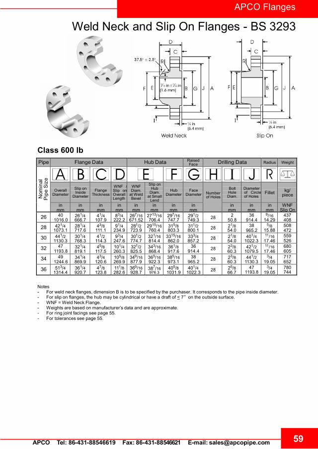
59APCO Tel: 86-431-88546619 Fax: 86-431-88546621 E-mail: [email protected]
APCO Flanges
Weld Neck and Slip On Flanges - BS 3293
Class 600 lbPipe Flange Data Hub Data Raised
Face Drilling Data Radius Weight
Nom
inal
Pip
eS
ize
Overall
Diameter
Slip onInside
Diameter
Flange
Thickness
WNF /Slip on Overall Length
WNF Diam.
at WeldBevel
Slip onHub
Diam.at Small
Lend
Hub
Diameter
Face
Diameter
Number of Holes
Bolt HoleDiam.
Diameter of Circle of Holes
Fillet
kg/
piece
in mm
in mm
in mm
in mm
in mm
in mm
in mm
in mm
in mm
in mm
in mm
WNF Slip On
26 401016.0
261/4666.7
41/4107.9
83/4222.2
267/16671.52
2713/16706.4
297/16747.7
291/2749.3 28 2
50.836
914.49/16
14.29437408
28 421/41073.1
281/4717.6
43/8111.1
91/4234.9
281/2723.9
2915/16760.4
315/8803.3
311/2800.1 28 21/8
54.038
965.25/8
15.88508472
30 441/21130.3
301/4768.3
41/2114.3
93/4247.6
301/2774.7
321/16814.4
3315/16862.0
333/4857.2 28 21/8
54.0401/4
1022.311/1617.46
559526
32 471193.8
321/4819.1
45/8117.5
101/4260.3
321/2825.5
343/16868.4
361/8917.6
36914.4 28 23/8
60.3421/2
1079.511/1617.46
680605
34 491244.6
341/4869.9
43/4120.6
105/8269.9
349/16877.9
365/16922.3
385/16973.1
38965.2 28 23/8
60.3441/2
1130.33/4
19.05717652
36 513/41314.4
361/4920.7
47/8123.8
111/8282.6
369/16928.7
387/16976.3
405/81031.9
401/41022.3 28 25/8
66.747
1193.83/4
19.05780744
Notes- For weld neck flanges, dimension B is to be specified by the purchaser. It corresponds to the pipe inside diameter.- For slip on flanges, the hub may be cylindrical or have a draft of < 7° on the outside surface.- WNF = Weld Neck Flange.- Weights are based on manufacturer’s data and are approximate.- For ring joint facings see page 55.- For tolerances see page 55.

APCO Flanges
BS 4504 Circular Flanges - General
60 APCO Tel: 86-431-88546619 Fax: 86-431-88546621 E-mail: [email protected]
British Standard BS 4504 : Section 3.1 : 1989 - Circular Flanges for Pipes, Valves and Fittings (PN Designated), Specification for Steel Flanges. This covers flanges in nominal pressure ranges PN 2.5 to PN 40 and nominal sizes up to DN 4000 (see table below). BS 4504 substantially agrees with ISO 7005-1 : 1992 (E) Part 1 : Steel Flanges.
BS 4504 : 1969 is still commonly used. This older standard allows for manufacture from bar, whereas the latest standard specifies that forging or plate are to be used, which can be significantly more expensive. There are minor differences in dimensions between the two versions. The following tables are based on the later version.
Summary of flanges covered by BS 4504 : Section 3.1
Code No. Description PN Range DN Range
101 Plate flange for welding (see page 65)
PN 2.5 DN 10 to DN 2000 PN 6, 10, 16, 25, 40 DN 10 to DN 600
102
Loose plate flange with weld-on plate collar or for lapped pipe end
(Weld-on plate collar = Code 1321 Lapped pipe end = Code 1331)
PN 6, 10, 16, 25, 40
DN 10 to DN 600
10 4
Loose plate flange with weld-neck collar (Weld- neck collar = Code 1341) PN 6, 10, 16, 25, 40 DN 10 to DN 600
105
Blank flange (see page 70)
PN 2.5, 6 DN 10 to DN 2000 PN 10, 16 DN 10 to DN 1200 PN 25, 40 DN 10 to DN 600
111
Weld-neck flange (see page 66)
PN 2.5, 6, 10, 16 DN 10 to DN 20002 PN 25 DN 10 to DN 1000 PN 40 DN 10 to DN 600
112 Hubbed slip-on flange for welding (see page 68)
PN 6 DN 10 to DN 300 PN 10, 16, 25, 40 DN 10 to DN 600
113 Hubbed threaded flange (see page 69) PN 6, 10, 16, 25, 40 DN 10 to DN 150
121 Integral flange PN 6, 10, 16, 25 DN 10 to DN 2000 PN 40 DN 10 to DN 600
Notes - Flanges > DN 2000, are not covered in this summary. - Dimensions: Nominal sizes, DN followed by a numerical designation of size (a convenient round number for reference
purposes), are used as defined in ISO 6708. - Pressure Ratings: Nominal pressures, i.e. PN followed by a numerical designation of size (a convenient round number for
reference purposes), are used as defined in ISO 7268. 1 Dimensions for these flanges are not covered in this summary. 2 The DN range for weld neck flanges extends to DN 4000 for PN 2.5, to DN 3600 for PN 6, and to DN 3000 for PN 10.
Designations/Marking
Marking. All flanges are marked with BS number, code number, PN, DN, material designation, manufacturers name or trade mark, cast number or melt identification, thread identification, An example follows:
BS 4504/111/B - PN 16 - DN 400 - B4 - XXX - 12345 Cast Number or melt identification
Manufacturer’s name or trade mark
Material designation
Nominal size, DN
Nominal Pressure, PN
Flange face type (A - H)
Flange code number
British standard number

61 APCO Tel: 86-431-88546619 Fax: 86-431-88546621 E-mail: [email protected]
APCO Flanges
BS 4504 Circular Flanges - General
Dimensions and Tolerances
Dimension Range Tolerance mm
Flange Facings (see page 8-63)
Eccentricity of machined facing diameters < DN 100 1.0 > DN 100 2.0
(type B facing height)
2 mm +0, -1.0 3 mm +0, -2.0 4 mm +0, -3.0 5 mm +0, -4.0 6 mm +0, -5.0
b (type C and E facing height) All +0.5, -0 b (type G facing height) All +0, -0.5
b (type H facing height, outer) All +0.2, -0 c (type D and F facing height) All +0, -0.5 d (type H facing height, inner) All +0.5, -0
B and E (facing diameters) All +0, -0.5 C and D (facing diameters) All +0.5, -0
Surface Finish
Facing types A, B, E and F
All, turning Ra = 3.2 µm min 12.5 µm max
All, other than turning Ra = 3.2 µm min 6.3 µm max
Facing types C, D, G and H All Ra = 0.8 µm min 3.2 µm max
Flange Drilling
Details (see page 8-64)
B (diameter of bolt circle) Bolt sizes M10 to M24 ±0.9 Bolt sizes M27 to M45 ±1.4
Centre to centre of adjacent bolt holes Bolt sizes M10 to M24 ±0.45 Bolt sizes M27 to M45 ±0.7
All
A (outside diameter)
< DN 150 ±2.0 > DN 150 < DN 500 ±3.0
> DN 500 < DN 1200 ±5.0 > DN 1200 < DN 1800 ±7.0
> DN 1800 ±10.0
C (flange thickness, machined on both faces)
< 18 mm thickness ±1.0 > 18 mm < 50 mm
thickness ±1.0
> 50 mm thickness ±1.0
C (flange thickness, machined on front face)
< 18 mm thickness +2.0, -1.0 > 18 mm < 50 mm
thickness +4.0, -1.5 > 50 mm thickness +7.0, -2.0
Weld Neck Flanges, Code 111
(see page 8-66)
B (outside diameter of hub at welding end)
< DN 125 +3.0, -0 > DN 125 < DN 1200 +4.5, -0
> DN 1200 +6.0, -0
F (hub diameter)
< DN 50 +0, -2.0 > DN 50 < DN 150 +0, -4.0 > DN 150 < DN 300 +0, -6.0 > DN 300 < DN 600 +0, -8.0
> DN 600 < DN 1200 +0, -10.0
D (length through hub) < DN 80 ±1.5
> DN 80 < DN 250 ±2.0 > DN 250 ±3.0
Slip on, Code 112 (see page 8-68) and Threaded,
Code 113 (see page 8-69)
Flanges
E (slip on flange hub diameter) B (threaded flange hub diameter)
< DN 50 +1.0, -0 > DN 50 < DN 150 +2.0, -0 > DN 150 < DN 300 +4.0, -.0 > DN 300 < DN 600 +8.0, -0
> DN 600 < DN 1200 +12.0, -0 > DN 1200 < DN 1800 +16.0, -0
> DN 1800 +20.0, -0
B (slip on bore diameter)
< DN 100 +0.5, -0 > DN 100 < DN 400 +1.0, .0 > DN 400 < DN 600 +1.5, .0
> DN 600 +3.0, -0 D (length through hub) Same as Weld Neck D
Blank Flanges, Code 105
(see page 8-70)
B (flange thickness) Same as C for all other flanges C (unmachined centre portion) Maximum specified

APCO Flanges
BS 4504 Circular Flanges - General
62 APCO Tel: 86-431-88546619 Fax: 86-431-88546621 E-mail: [email protected]
Weld Neck Flange - Welding Ends
Welding end for Wall Thickness (t) from 5 mm to22.2 mm
Welding end for Wall Thickness (t) > 22.2 mm
Flange Facings - BS 4504BS 4504 flange facing types A to H are defined below. The dimensions vary with pipe size (DN) and pressure rating (PN) as detailed in the following table.

63 APCO Tel: 86-431-88546619 Fax: 86-431-88546621 E-mail: [email protected]
APCO Flanges
BS 4504 Circular Flanges - General
BS 1503 Grade ASTM A 182 Grade 304S11 F304L 304S31 F304 304S51 F304H 347S31 F347 347S51 F347H 321S31 F321 321S51 F321H 316S11 F316L 316S31 F316 316S51 F316H 310S31 F310
Flange facing dimensions (BS 4504)
DN
mm
Face Dimensions
PN
2.5
PN
6
PN
10
PN
16
PN
25
PN
40
mm
mm
mm
mm
mm
mm
mm
mm
mm
mm 10 35 35 40 40 40 40 34 35 24 23 2 4 3 2 - 5 15 40 40 45 45 45 45 39 40 29 28 2 4 3 2 - 5 20 50 50 58 58 58 58 50 51 36 35 2 4 3 2 41°16' 5 25 60 60 68 68 68 68 57 58 43 42 2 4 3 2 41°16' 5 32 70 70 78 78 78 78 65 66 51 50 2 4 3 2 41°16' 5 40 80 80 88 88 88 88 75 76 61 60 3 4 3 2 41°16' 5 50 90 90 102 102 102 102 87 88 73 72 3 4 3 2 41°16' 5 65 110 110 122 122 122 122 109 110 95 94 3 4 3 2 41°16' 5 80 128 128 138 138 138 138 120 121 106 105 3 4 3 2 41°16' 5 100 148 148 158 158 162 162 149 150 129 128 3 4.5 3.5 2.5 32°15' 6 125 178 178 188 188 188 188 175 176 155 154 3 4.5 3.5 2.5 32°15' 6 150 202 202 212 212 218 218 203 204 183 182 3 4.5 3.5 2.5 32°15' 6 200 258 258 268 268 278 285 259 260 239 238 3 4.5 3.5 2.5 32°15' 6 250 312 312 320 320 335 345 312 313 292 291 3 4.5 3.5 2.5 32°15' 6 300 365 365 370 378 395 410 363 364 343 342 4 4.5 3.5 2.5 32°15' 6 350 415 415 430 438 450 465 421 422 395 394 4 5 4 3 27°24' 7 400 465 465 482 490 505 535 473 474 447 446 4 5 4 3 27°24' 7 450 520 520 532 550 555 560 523 524 497 496 4 5 4 3 27°24' 7 500 570 570 585 610 615 615 575 576 549 548 4 5 4 3 27°24' 7 600 670 670 685 725 720 735 675 676 649 648 5 5 4 3 27°24' 7 700 775 775 800 795 820 - 777 778 751 750 5 5 4 3 27°24' 7 800 880 880 905 900 930 - 882 883 856 855 5 5 4 3 27°24' 7 900 980 980 1005 1000 1030 - 987 988 961 960 5 5 4 3 27°24' 7
1000 1080 1080 1110 1115 1140 - 1092 1094 1062 1060 5 6 5 4 28°39' 8 1200 1280 1295 1330 1330 1350 - 1292 1294 1262 1260 5 6 5 4 28°39' 8 1400 1480 1510 1535 1530 1560 - 1492 1494 1462 1460 5 6 5 4 28°39' 8 1600 1690 1710 1760 1750 1780 - 1692 1694 1662 1660 5 6 5 4 28°39' 8 1800 1890 1920 1960 1950 1985 - 1982 1894 1862 1860 5 6 5 4 28°39' 8 2000 2090 2125 2170 2150 2210 - 2092 2094 2062 2060 5 6 5 4 28°39' 8
Manufacture ❍ Materials. Flange codes 111 112 and 113 are
manufactured from a forging or steel casting. Stainless steel forgings conforming to ASTM A 182, have an additional requirement for grade F304L and F316L that carbon content (by ladle analysis) shall be 0.030% max. Forgings to BS 1503 and comparable ASTM standard grades specified in BS 4504 are as listed in the following table.
BS and ASTM forging grades in BS 4504

APCO Flanges
64 APCO Tel: 86-431-88546619 Fax: 86-431-88546621 E-mail: [email protected]
DN
PN
Bolt Holes
mm mm mm No. Boltsize
350
2.5 & 6 490 445 22 12 M2010 505 460 22 16 M2016 520 470 26 16 M2425 555 490 33 16 M3040 580 510 36 16 M33
400
2.5 & 6 540 495 22 16 M2010 565 515 26 16 M2416 580 525 30 16 M2725 620 550 36 16 M3340 660 585 39 16 M36
450
2.5 & 6 595 550 22 16 M2010 615 565 26 20 M2416 640 585 30 20 M2725 670 600 36 20 M3340 685 610 39 20 M36
500
2.5 & 6 645 610 22 20 M2010 670 620 26 20 M2416 715 650 33 20 M3025 730 660 36 20 M3340 755 670 42 20 M39
600
2.5 & 6 755 705 26 20 M2410 780 725 30 20 M2716 840 770 36 20 M3325 845 770 39 20 M3640 890 795 48 20 M45
700
2.5 & 6 860 810 26 24 M2410 895 840 30 24 M2716 910 840 36 24 M3325 960 875 42 24 M39
800
2.5 & 6 975 920 30 24 M2710 1015 950 33 24 M3016 1025 950 39 24 M3625 1085 990 48 24 M45
9002.5 & 6 1075 1020 30 24 M27
10 1115 1050 33 28 M3016 1125 1050 39 28 M3625 1185 1090 48 28 M45
1000
2.5 & 6 1175 1120 30 28 M2710 1230 1160 36 28 M3316 1255 1170 42 28 M3925 1320 1210 56 28 M52
1200
2.5 1375 1320 30 32 M276 1405 1340 33 32 M30
10 1455 1380 39 32 M3616 1485 1390 48 32 M4525 1530 1420 56 32 M52
1400
2.5 1575 1520 30 36 M276 1630 1560 36 36 M33
10 1675 1590 42 36 M3916 1685 1590 48 36 M4525 1755 1640 62 36 M56
1600
2.5 1790 1730 30 40 M276 1830 1760 36 40 M33
10 1915 1820 48 40 M4516 1930 1820 56 40 M5225 1975 1860 62 40 M56
1800
2.5 1990 1930 30 44 M276 2045 1970 39 44 M36
10 2115 2020 48 44 M4516 2130 2020 56 44 M5225 2185 2070 70 44 M64
2000
2.5 2190 2130 30 48 M276 2265 2180 42 48 M39
10 2325 2230 48 48 M4516 2345 2230 62 48 M5625 2425 2300 70 48 M64
Flange Drilling Details - BS 4504.
DN
PN
Bolt Holes
mm mm mm No. Boltsize
10 2.5 & 6 75 50 11 4 M1010,16, 90 60 14 4 M12
15
2.5 & 6 80 55 11 4 M1010 & 16 95 65 14 4 M1225 & 40 95 65 14 4 M12
20
2.5 & 6 90 65 11 4 M1010 & 16 105 75 14 4 M1225 &40 105 75 14 4 M12
25
2.5 & 6 100 75 11 4 M1010 & 16 115 85 14 4 M1225&40 115 85 14 4 M12
32
2.5 & 6 120 90 14 4 M1210 & 16 140 100 18 4 M1625 & 40 140 100 18 4 M16
40
2.5 & 6 130 100 14 4 M1210 & 16 150 110 18 4 M1625 &40 150 110 18 4 M16
50
2.5 & 6 140 110 14 4 M1210 & 16 165 125 18 4 M1625 &40 165 125 18 4 M16
65
2.5 & 6 160 130 14 4 M1210 & 16 185 145 18 4/8 M1625 & 40 185 145 18 8 M16
80
2.5 & 6 190 150 18 4 M1610 & 16 200 160 18 8 M1625 &40 200 160 18 8 M16
100
2.5 & 6 210 170 18 4 M1610 & 16 220 180 18 8 M1625 &40 235 190 22 8 M20
125
2.5 & 6 240 200 18 8 M1610 & 16 250 210 18 8 M1625 & 40 270 220 26 8 M24
150
2.5 & 6 265 225 18 8 M1610 & 16 285 240 22 8 M2025 & 40 300 250 26 8 M24
200
2.5 & 6 320 280 18 8 M1610 & 16 340 295 22 8/12 M20
25 360 310 26 12 M2440 375 320 30 12 M27
250
2.5 & 6 375 335 18 12 M1610 395 350 22 12 M2016 405 355 26 12 M2425 425 370 30 12 M2740 450 385 33 12 M30
300
2.5 & 6 440 395 22 12 M2010 445 400 22 12 M2016 460 410 26 12 M2425 485 430 30 16 M2740 515 450 33 16 M30

65 APCO Tel: 86-431-88546619 Fax: 86-431-88546621 E-mail: [email protected]
APCO Flanges
DN
PN
mm
mm
mm
10 2.5, 6 75 12
18.0 10 &16 90 14 25 & 40 90 14
15
2.5 & 6 80 12 22 10 &16 95 14
25 & 40 95 14
20 2.5 & 6 90 14
27.5 10 &16 105 16 25 & 40 105 16
25
2.5 & 6 100 14 34.5 10 &16 115 16
25 & 40 115 16
32 2.5 & 6 120 16
43.5 10 &16 140 18 25 & 40 140 18
40
2.5 & 6 130 16 49.5 10 &16 150 18
25 & 40 150 18
50 2.5 & 6 140 16
61.5 10 & 16 165 20 25 & 40 165 20
65
2.5 & 6 160 16 77.5 10 & 16 185 20
25 & 40 185 22
80 2.5 & 6 190 18
90.5 10 &16 200 20 25 & 40 200 24
100
2.5 & 6 210 18 116.0 10 &16 220 22
25 & 40 235 26
125 2.5 & 6 240 20
141.5 10 & 16 250 22 25 & 40 270 28
150
2.5 & 6 265 20 170.5 10 & 16 285 24
25 & 40 300 30
200 2.5 & 6 320 22
221.5 10 &16 340 24 25 360 32 40 375 36
250
2.5 & 6 375 24
276.5 10 395 26 16 405 29 25 425 35 40 450 42
by p
urch
aser
Plate Flanges (Code 101) - BS 4504
.
Notes - Dimension B is the flange thickness with or without a
raised face. - For drilling details see page 64. - For tolerances see page 61. - For facing types and dimensions see page 62.
DN
PN
mm
mm
mm
300
2.5 & 6 440 24
327.5 10 445 26 16 460 32 25 485 38 40 515 48
350
2.5 & 6 490 26 359.5 10 505 28
16 520 35 359.0 25 555 42
359.5 40 580 54
400
2.5 & 6 540 28
411.0 10 565 32 16 580 38 25 620 46 40 660 60
450
2.5 & 6 595 30
462.0 10 615 36 16 640 42 25 670 50 40 685 66
500
2.5 & 6 645 30
513.5 10 670 38 16 715 46 25 730 56 40 755 72
600
2.5 & 6 755 32
616.5 10 780 42 16 840 52 25 845 68 40 890 84
700 2.5 860 36
To
be
spec
ified
800 2.5 975 38 900 2.5 1075 40 1000 2.5 1175 42 1200 2.5 1375 44 1400 2.5 1575 48 1600 2.5 1790 51 1800 2.5 1990 54 2000 2.5 2190 58
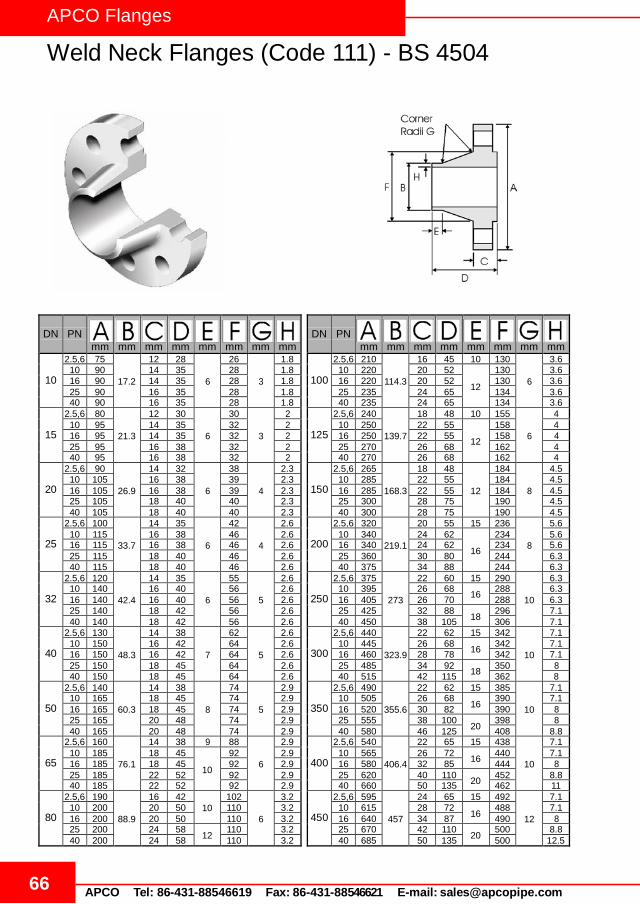
APCO Flanges
66 APCO Tel: 86-431-88546619 Fax: 86-431-88546621 E-mail: [email protected]
Weld Neck Flanges (Code 111) - BS 4504
DN
PN
mm
mm
mm
mm
mm
mm
mm
mm
DN
PN
mm
mm
mm
mm
mm
mm
mm
mm
10
2.5,6 75 17.2
12 28
6
26
3
1.8 100
2.5,6 210 114.3
16 45 10 130
6
3.6 10 90 14 35 28 1.8 10 220 20 52
12
130 3.6 16 90 14 35 28 1.8 16 220 20 52 130 3.6 25 90 16 35 28 1.8 25 235 24 65 134 3.6 40 90 16 35 28 1.8 40 235 24 65 134 3.6
15
2.5,6 80 21.3
12 30
6
30
3
2
125
2.5,6 240 139.7
18 48 10 155
6
4 10 95 14 35 32 2 10 250 22 55
12
158 4 16 95 14 35 32 2 16 250 22 55 158 4 25 95 16 38 32 2 25 270 26 68 162 4 40 95 16 38 32 2 40 270 26 68 162 4
20
2.5,6 90 26.9
14 32
6
38
4
2.3
150
2.5,6 265 168.3
18 48
12
184
8
4.5 10 105 16 38 39 2.3 10 285 22 55 184 4.5 16 105 16 38 39 2.3 16 285 22 55 184 4.5 25 105 18 40 40 2.3 25 300 28 75 190 4.5 40 105 18 40 40 2.3 40 300 28 75 190 4.5
25
2.5,6 100 33.7
14 35
6
42
4
2.6
200
2.5,6 320 219.1
20 55 15 236
8
5.6 10 115 16 38 46 2.6 10 340 24 62
16
234 5.6 16 115 16 38 46 2.6 16 340 24 62 234 5.6 25 115 18 40 46 2.6 25 360 30 80 244 6.3 40 115 18 40 46 2.6 40 375 34 88 244 6.3
32
2.5,6 120 42.4
14 35
6
55
5
2.6
250
2.5,6 375 273
22 60 15 290
10
6.3 10 140 16 40 56 2.6 10 395 26 68
16 288 6.3 16 140 16 40 56 2.6 16 405 26 70 288 6.3 25 140 18 42 56 2.6 25 425 32 88
18 296 7.1 40 140 18 42 56 2.6 40 450 38 105 306 7.1
40
2.5,6 130 48.3
14 38
7
62
5
2.6
300
2.5,6 440 323.9
22 62 15 342
10
7.1 10 150 16 42 64 2.6 10 445 26 68
16 342 7.1 16 150 16 42 64 2.6 16 460 28 78 342 7.1 25 150 18 45 64 2.6 25 485 34 92
18 350 8 40 150 18 45 64 2.6 40 515 42 115 362 8
50
2.5,6 140 60.3
14 38
8
74
5
2.9
350
2.5,6 490 355.6
22 62 15 385
10
7.1 10 165 18 45 74 2.9 10 505 26 68
16 390 7.1 16 165 18 45 74 2.9 16 520 30 82 390 8 25 165 20 48 74 2.9 25 555 38 100
20 398 8 40 165 20 48 74 2.9 40 580 46 125 408 8.8
65
2.5,6 160 76.1
14 38 9 88
6
2.9
400
2.5,6 540 406.4
22 65 15 438
10
7.1 10 185 18 45
10
92 2.9 10 565 26 72 16 440 7.1
16 185 18 45 92 2.9 16 580 32 85 444 8 25 185 22 52 92 2.9 25 620 40 110
20 452 8.8 40 185 22 52 92 2.9 40 660 50 135 462 11
80
2.5,6 190 88.9
16 42 10
102
6
3.2
450
2.5,6 595 457
24 65 15 492
12
7.1 10 200 20 50 110 3.2 10 615 28 72
16 488 7.1 16 200 20 50 110 3.2 16 640 34 87 490 8 25 200 24 58
12 110 3.2 25 670 42 110 20 500 8.8
40 200 24 58 110 3.2 40 685 50 135 500 12.5

APCO Flanges
67 APCO Tel: 86-431-88546619 Fax: 86-431-88546621 E-mail: [email protected]
Weld Neck Flanges (Code 111) - BS 4504
DN
PN
mm
mm
mm
mm
mm
mm
mm
mm
500
2.5,6 645
508
24 68 15 538
12
7.1 10 670 28 75
16 540 7.1 16 715 34 90 546 8 25 730 44 125
20 558 10 40 755 52 140 562 14.2
600
2.5,6 755
610
24 70 16 640
12
7.1 10 780 28 80
18 640 7.1 16 840 36 95 650 8.8 25 845 46 125
20 660 11 40 890 60 150 666 16
700
2.5 860
711
24 70 16 740
12
-1 6 860 24 70 740 7.1
10 895 30 80 18 746 8
16 910 36 100 750 8.8 25 960 46 125 20 760 12.5
800
2.5 975
813
26 70 16 842
12
-1 6 975 24 70 842 7.1
10 1015 32 90 18 848 8 16 1025 38 105 20 848 10 25 1085 50 135 22 864 14.2
900
2.5 1075
914
26 70 16 942
12
-1 6 1075 26 70 942 7.1
10 1115 34 95 20 948 10
16 1125 40 110 948 10 25 1185 54 145 24 968 16
1000
2.5 1175 1016
26 70 16 1045
12
-1 6 1175 26 70 1045 7.1
10 1230 34 95 20 1050 10 16 1255 42 120 22 1056 10 25 1320 58 155 24 1070 17.5
1200
2.5 1375 1220
26 70 16 1245 16 -1 6 1405 28 90 20 1248
12 8
10 1455 38 115 25 1256 11 16 1485 48 130 30 1260 12.5
1400
2.5 1575 1420
26 70 16 1445 16 -1 6 1630 32 90 20 1452
12 8
10 1675 42 120 25 1460 12 16 1685 52 145 30 1465 14.2
1600
2.5 1790 1620
26 80 20 1645 16 -1
6 1830 34 90 1655 12
9 10 1915 46 130 25 1666 14 16 1930 58 160 35 1668 16
1800
2.5 1990 1820
26 80 20 1845 16 -1
6 2045 36 100 1855 15
10 10 2115 50 140 30 1866 15 16 2130 62 170 35 1870 17.5
2000
2.5 2190 2020
26 80 22 2045 16 -1 6 2265 38 110 25 2058
15 11
10 2325 54 150 30 2070 16 16 2345 66 190 40 2072 20
Notes - For drilling details see page 64. - For tolerances see page 61. - For facing types and dimensions see page 62. 1 To be specified by the purchaser.

APCO Flanges
68 APCO Tel: 86-431-88546619 Fax: 86-431-88546621 E-mail: [email protected]
Slip On Flanges (Code 112) - BS 4504
Notes - The hubs of slip on (code 112) flanges are parallel or have a draft <7 degrees. - For drilling details see page 64. - For tolerances see page 61. - For facing types and dimensions see page 62.
DN
PN
mm
mm
mm
mm
mm
mm
10 6 75
18.0 12 20 25
3 10 &16 90 14 20 30 25 & 40 90 16 22 30
15
6 80 22
12 20 30 3 10 &16 95 14 20 35
25 & 40 95 16 22 35
20 6 90
27.5 14 24 40
4 10 &16 105 16 24 45 25 & 40 105 18 26 45
25
6 100 34.5
14 24 50 4 10 &16 115 16 24 52
25 & 40 115 18 28 52
32 6 120
43.5 14 26 60
5 10 &16 140 16 26 60 25 & 40 140 18 30 60
40
6 130 49.5
14 26 70 5 10 &16 150 16 26 70
25 & 40 150 18 32 70
50 6 140
61.5 14 28 80
5 10 & 16 165 18 28 84 25 & 40 165 20 34 84
65
6 160 77.5
14 32 100 6 10 & 16 185 18 32 104
25 & 40 185 22 38 104
80 6 190
90.5 16 34 110
6 10 &16 200 20 34 118 25&40 200 24 40 118
100
6 210 116.0
16 40 130 6 10 &16 220 20 40 140
25&40 235 24 44 145 125
6 240 141.5
18 44 160 6 10 & 16 250 22 44 168
25 & 40 270 26 48 170 150
6 265 170.5
18 44 185 8 10 & 16 285 22 44 195
25 & 40 300 28 75 190
DN
PN
mm
mm
mm
mm
mm
mm
200
6 320 221.5
20 44 240 8
10 &16 340 24 44 246 25 360 30 52 256 40 375 34 52 260
250
6 375 276.5
22 44 295
10 10 395 26 46 298 16 405 26 46 298 25 425 32 60 310 40 450 38 60 312
300
6 440 327.5
22 44 355
10 10 445 26 46 350 16 460 28 46 350 25 485 34 67 364 40 515 42 67 380
350
10 505 359.5 26 53 400 10
16 520 359.0 30 57 400 25 555 359.5 38 72 418 40 580 46 72 424
400
10 565 411.0
26 57 456 10
16 580 32 63 456 25 620 40 78 472 40 660 50 78 478
450
10 615 462.0
28 63 502 12
16 640 34 68 502 25 670 42 84 520 40 685 50 84 522
500
10 670 513.5
28 67 559 12
16 715 34 73 559 25 730 44 90 580 40 755 52 90 576
600
10 780 616.5
28 75 658 12
16 840 36 83 658 25 845 46 100 684 40 890 60 100 686
- - - - - - - - - - - - - - - -

APCO Flanges
69 APCO Tel: 86-431-88546619 Fax: 86-431-88546621 E-mail: [email protected]
Threaded Flanges (Code 113) - BS 4504
.
Notes - Threaded flange (code 113) threads are tapered or parallel.
BS 21 or ANSI/ASME B1.20.1 threads may be specified. - The hubs of threaded (code 113) flanges are parallel or have a draft <7 degrees. - For drilling details see page 64. - For tolerances see page 61. - For facing types and dimensions see page 62.
DN
PN
mm
mm
mm
mm
mm
10 6 75 25 12 20
3 16 90 30 14 20 40 90 30 16 22
15
6 80 30 12 20 3 16 95 35 14 20
40 95 35 16 22
20 6 90 40 14 24
4 16 105 45 16 24 40 105 45 18 26
25
6 100 50 14 24 4 16 115 52 16 24
40 115 52 18 28
32 6 120 60 14 26
5 16 140 60 16 26 40 140 60 18 30
40
6 130 70 14 26 5 16 150 70 16 26
40 150 70 18 32
50 6 140 80 14 28
5 16 165 84 18 28 40 165 84 20 34
65
6 160 100 14 32 6 16 185 104 18 32
40 185 104 22 38
80 6 190 110 16 34
6 16 200 118 20 34 40 200 118 24 40
100
6 210 130 16 40 6 16 220 140 20 40
40 235 145 24 44
DN
PN
mm
mm
mm
mm
mm 125
6 240 160 18 44 6 16 250 168 22 44
40 270 170 26 48 150
6 265 185 18 44 8 16 285 195 22 44
40 300 200 28 52 200
6 320 240 20 44 8 16 340 246 24 44
40 375 260 34 52 250
6 375 295 22 44 10 16 405 298 26 46
40 450 312 38 60 300
6 440 355 22 44 10 16 460 350 28 46
40 515 380 42 67
350 16 520 400 30 57 10 40 580 424 46 72
400 16 580 456 32 63 10 40 660 478 50 78
450 16 640 502 34 68 12 40 685 522 50 84
500 16 715 559 34 73 12 40 755 576 52 90
600 16 840 658 36 83 12 40 890 686 60 100
700 16 910 760 36 83 12 800 16 1025 864 38 90 12 900 16 1125 968 40 94 12
1000 16 1255 1072 42 100 12 - - - - - - -

APCO Flanges
70 APCO Tel: 86-431-88546619 Fax: 86-431-88546621 E-mail: [email protected]
DN
PN
mm
mm
mm
300
2.5 & 6 440 22 285 10 445 26 285 16 460 28 285 25 485 34 285 40 515 42 285
350
2.5 & 6 490 22 325 10 505 26 325 16 520 30 325 25 555 38 325 40 580 46 325
400
2.5 & 6 540 22 375 10 565 26 375 16 580 32 375 25 620 40 375 40 660 50 375
450
2.5 & 6 595 24 425 10 615 28 425 16 640 34 425 25 670 42 425 40 685 54 425
500
2.5 & 6 645 24 475 10 670 28 475 16 715 36 475 25 730 45 475 40 755 56 475
600
2.5 & 6 755 34 575 10 780 34 575 16 840 44 575 25 845 54 575 40 890 70 575
700
2.5 860 36 - 6 860 38 -
10 895 38 670 16 910 48 670
800
2.5 975 38 - 6 975 42 -
10 1015 42 770 16 1025 52 770
900
2.5 1075 40 - 6 1075 46 -
10 1115 46 860 16 1125 58 860
1000
2.5 1175 42 - 6 1175 52 -
10 1230 52 960 16 1255 64 960
1200
2.5 1375 44 - 6 1405 60 -
10 1455 60 1160 16 1485 76 1160
1400 2.5 1575 48 - 6 1630 68 -
1600 2.5 1790 51 - 6 1830 76 -
1800 2.5 1990 54 - 6 2045 84 -
2000 2.5 2190 58 - 6 2265 92 -
DN
PN
mm
mm
mm
10 2.5, 6 75 12 -
10 &16 90 14 - 25 & 40 90 16 -
15
2.5 & 6 80 12 - 10 &16 95 14 - 25 & 40 95 16 -
20
2.5 & 6 90 14 - 10 &16 105 16 - 25 & 40 105 18 -
25
2.5 & 6 100 14 - 10 &16 115 16 - 25 & 40 115 18 -
32
2.5 & 6 120 14 - 10 &16 140 16 - 25 & 40 140 18 -
40
2.5 & 6 130 14 - 10 &16 150 16 - 25 & 40 150 18 -
50
2.5 & 6 140 14 - 10 & 16 165 18 - 25 & 40 165 20 -
65
2.5 & 6 160 14 55 10 & 16 185 18 55 25 & 40 185 22 55
80
2.5 & 6 190 16 70 10 &16 200 20 70 25&40 200 24 70
100
2.5 & 6 210 16 90 10 &16 220 20 90 25&40 235 24 90
125
2.5 & 6 240 18 115 10 & 16 250 22 115 25 & 40 270 26 115
150
2.5 & 6 265 18 140 10 & 16 285 22 140 25 & 40 300 28 140
200
2.5 & 6 320 20 190 10 &16 340 24 190
25 360 30 190 40 375 34 190
250
2.5 & 6 375 22 235 10 395 26 235 16 405 26 235 25 425 32 235 40 450 38 235
Blank Flanges (Code 105) - BS 4504
.
Notes - Dimension B is the range thickness with or without a
raised face. - Dimension C is the maximum diameter of the centre
portion of a blank flange face which need not be machined.
- For drilling details see page 64. - For tolerances see page 61. - For facing types and dimensions see page 62.

APCO Flanges
71 APCO Tel: 86-431-88546619 Fax: 86-431-88546621 E-mail: [email protected]
BS 10 : 1962
British Standard BS 10 : 1962 - Specification for Flanges and Bolting for Pipes, Valves, and Fittings. This covers plain, boss, integrally cast or forged, and welding neck type flanges, in ten tables. Although BS 10 is obsolescent, it remains in use for the dimensions of light duty, economy stainless steel flanges in applications where corrosion resistance and/or hygiene, rather than high pressures and temperatures, are the primary considerations. The following tables detail the applicable standard dimensions from Tables D, E, F and H of BS 10.
Flange Dimensions Based on Tables D and E of BS 10 : 1962 Common BS 10 Table D Dimensions BS 10 Table E Dimensions Flange Size Designation
(Nominal Bore of Pipe)
Overall
Diameter of Flange
Flange
Thickness
Bolt
Circle Diameter
Number of Bolts
Diameter
of Bolts
Overall
Diameter of Flange
Flange
Thickness
Bolt
Circle Diameter
Number
of Bolts
Diameter
of Bolts
in in in in in in in in in 1/2 33/4 3/16 25/8 4 1/2 33/4 1/4 25/8 4 1/2 3/4 4 3/16 27/8 4 1/2 4 1/4 27/8 4 1/2 1 41/2 3/16 31/4 4 1/2 41/2 9/32 31/4 4 1/2
11/4 43/4 1/4 37/16 4 1/2 43/4 5/16 37/16 4 1/2
11/2 51/4 1/4 37/8 4 1/2 51/4 11/32 37/8 4 1/2 2 6 5/16 41/2 4 5/8 6 3/8 41/2 4 5/8
21/2 61/2 5/16 5 4 5/8 61/2 13/32 5 4 5/8 3 71/4 3/8 53/4 4 5/8 71/4 7/16 53/4 4 5/8
31/2 8 3/8 61/2 4 5/8 8 15/32 61/2 8 5/8
4 81/2 3/8 7 4 5/8 81/2 1/2 7 8 5/8 5 10 1/2 81/4 8 5/8 10 9/16 81/4 8 5/8
6 11 1/2 91/4 8 5/8 11 11/16 91/4 8 3/4 7 12 1/2 101/4 8 5/8 12 3/4 101/4 8 3/4
8 131/4 1/2 111/2 8 5/8 131/4 3/4 111/2 8 3/4 9 141/2 5/8 123/4 8 5/8 141/2 13/16 123/4 12 3/4
10 16 5/8 14 8 3/4 16 7/8 14 12 3/4
12 18 3/4 16 12 3/4 18 1 16 12 7/8 13 191/4 3/4 171/4 12 3/4 191/4 1 171/4 12 7/8
14 203/4 7/8 181/2 12 7/8 203/4 11/8 181/2 12 7/8
15 213/4 7/8 191/2 12 7/8 213/4 11/4 191/2 12 7/8 16 223/4 7/8 201/2 12 7/8 223/4 11/4 201/2 12 7/8
17 24 1 213/4 12 7/8 24 13/8 213/4 12 7/8 18 251/4 1 23 12 7/8 251/4 13/8 23 16 7/8
19 261/2 1 24 12 7/8 261/2 11/2 24 16 7/8 20 273/4 11/8 251/4 16 7/8 273/4 11/2 251/4 16 7/8
21 29 11/8 261/2 16 7/8 29 15/8 261/2 16 1 22 30 11/8 271/2 16 1 30 13/4 271/2 16 1 23 31 11/8 281/2 16 1 31 13/4 281/2 16 1 24 321/2 11/4 293/4 16 1 321/2 17/8 293/4 16 11/8
Note - Bolt hole diameters are as follows:
For 1/2 in and 5/8 in bolts, the bolt hole shall be 1/16 in larger than the bolt diameter. For 3/4 in bolts and larger, the bolt hole shall be not more than 1/8 in larger than the bolt diameter.

APCO Flanges
72 APCO Tel: 86-431-88546619 Fax: 86-431-88546621 E-mail: [email protected]
BS 10 : 1962
Flange Dimensions Based on Tables F and H of BS 10 : 1962 Common BS 10 Table F Dimensions BS 10 Table H Dimensions Flange Size Designation
(Nominal Bore of Pipe)
Overall
Diameter of Flange
Flange
Thickness
Bolt
Circle Diameter
Number
of Bolts
Diameter
of Bolts
Overall
Diameter of Flange
Flange
Thickness
Bolt
Circle Diameter
Number of Bolts
Diameter
of Bolts
1/2 33/4 3/8 25/8 4 1/2 41/2 1/2 31/4 4 5/8 3/4 4 3/8 27/8 4 1/2 41/2 1/2 31/4 4 5/8
1 43/4 3/8 37/16 4 5/8 43/4 9/16 37/16 4 5/8
11/4 51/4 1/2 37/8 4 5/8 51/4 11/16 37/8 4 5/8
11/2 51/2 1/2 41/8 4 5/8 51/2 11/16 41/8 4 5/8
2 61/2 5/8 5 4 5/8 61/2 3/4 5 4 5/8
21/2 71/4 5/8 53/4 8 5/8 71/4 3/4 53/4 8 5/8
3 8 5/8 61/2 8 5/8 8 7/8 61/2 8 5/8
31/2 81/2 3/4 7 8 5/8 81/2 7/8 7 8 5/8
4 9 3/4 71/2 8 5/8 9 1 71/2 8 5/8 5 11 7/8 91/4 8 3/4 11 11/8 91/4 8 3/4 6 12 7/8 101/4 12 3/4 12 11/8 101/4 12 3/4
7 131/4 7/8 111/2 12 3/4 131/4 11/4 111/2 12 3/4 8 141/2 1 123/4 12 3/4 141/2 11/4 123/4 12 3/4
9 16 11/8 14 12 7/8 16 13/8 14 12 7/8
10 17 11/8 15 12 7/8 17 13/8 15 12 7/8 12 191/4 11/4 171/4 16 7/8 191/4 15/8 171/4 16 7/8
13 203/4 13/8 181/2 16 1 203/4 13/4 181/2 16 1 14 213/4 13/8 191/2 16 1 213/4 17/8 191/2 16 1 15 223/4 11/2 201/2 16 1 223/4 2 201/2 16 1 16 24 15/8 213/4 20 1 24 21/8 213/4 20 1 17 251/4 13/4 23 20 1 251/4 21/4 23 20 1 18 261/2 13/4 24 20 11/8 261/2 23/8 24 20 11/8 19 273/4 13/4 251/4 20 11/8 273/4 21/2 251/4 20 11/8 20 29 2 261/2 24 11/8 29 25/8 261/2 24 11/8
21 30 2 271/2 24 11/8 30 23/4 271/2 24 11/8 22 31 21/8 281/2 24 11/8 31 23/4 281/2 24 11/8
23 321/2 21/4 293/4 24 11/4 321/2 3 293/4 24 11/4 24 331/2 21/4 303/4 24 11/4 331/2 3 303/4 24 11/4
Note - Bolt hole diameters are as follows:
For 1/2 in and 5/8 in bolts, the bolt hole shall be 1/16 in larger than the bolt diameter. For 3/4 in bolts and larger, the bolt hole shall be not more than 1/8 in larger than the bolt diameter.
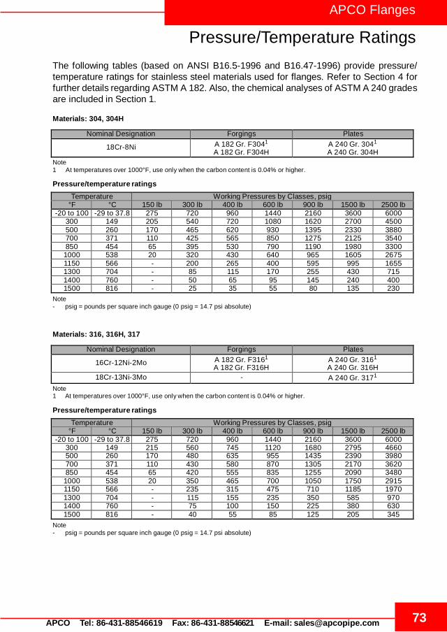
73 APCO Tel: 86-431-88546619 Fax: 86-431-88546621 E-mail: [email protected]
APCO Flanges
Pressure/Temperature Ratings
The following tables (based on ANSI B16.5-1996 and B16.47-1996) provide pressure/ temperature ratings for stainless steel materials used for flanges. Refer to Section 4 for further details regarding ASTM A 182. Also, the chemical analyses of ASTM A 240 grades are included in Section 1.
Materials: 304, 304H
Nominal Designation Forgings Plates
18Cr-8Ni A 182 Gr. F3041 A 182 Gr. F304H
A 240 Gr. 3041 A 240 Gr. 304H
Note 1 At temperatures over 1000°F, use only when the carbon content is 0.04% or higher.
Pressure/temperature ratings
Temperature Working Pressures by Classes, psig °F °C 150 lb 300 lb 400 lb 600 lb 900 lb 1500 lb 2500 lb
-20 to 100 -29 to 37.8 275 720 960 1440 2160 3600 6000 300 149 205 540 720 1080 1620 2700 4500 500 260 170 465 620 930 1395 2330 3880 700 371 110 425 565 850 1275 2125 3540 850 454 65 395 530 790 1190 1980 3300 1000 538 20 320 430 640 965 1605 2675 1150 566 - 200 265 400 595 995 1655 1300 704 - 85 115 170 255 430 715 1400 760 - 50 65 95 145 240 400 1500 816 - 25 35 55 80 135 230
Note - psig = pounds per square inch gauge (0 psig = 14.7 psi absolute)
Materials: 316, 316H, 317
Nominal Designation Forgings Plates
16Cr-12Ni-2Mo A 182 Gr. F3161 A 182 Gr. F316H
A 240 Gr. 3161 A 240 Gr. 316H
18Cr-13Ni-3Mo - A 240 Gr. 3171
Note 1 At temperatures over 1000°F, use only when the carbon content is 0.04% or higher.
Pressure/temperature ratings
Temperature Working Pressures by Classes, psig °F °C 150 lb 300 lb 400 lb 600 lb 900 lb 1500 lb 2500 lb
-20 to 100 -29 to 37.8 275 720 960 1440 2160 3600 6000 300 149 215 560 745 1120 1680 2795 4660 500 260 170 480 635 955 1435 2390 3980 700 371 110 430 580 870 1305 2170 3620 850 454 65 420 555 835 1255 2090 3480 1000 538 20 350 465 700 1050 1750 2915 1150 566 - 235 315 475 710 1185 1970 1300 704 - 115 155 235 350 585 970 1400 760 - 75 100 150 225 380 630 1500 816 - 40 55 85 125 205 345
Note - psig = pounds per square inch gauge (0 psig = 14.7 psi absolute)
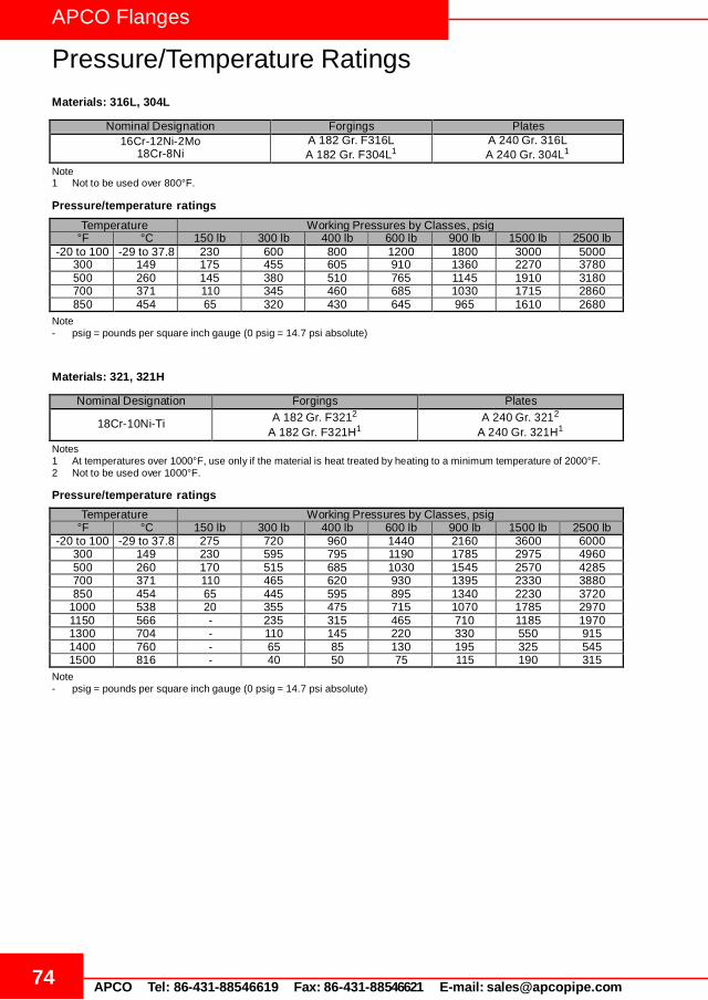
74 APCO Tel: 86-431-88546619 Fax: 86-431-88546621 E-mail: [email protected]
APCO Flanges
Pressure/Temperature Ratings
Materials: 316L, 304L
Nominal Designation Forgings Plates
16Cr-12Ni-2Mo 18Cr-8Ni
A 182 Gr. F316L A 182 Gr. F304L1
A 240 Gr. 316L A 240 Gr. 304L1
Note 1 Not to be used over 800°F.
Pressure/temperature ratings
Temperature Working Pressures by Classes, psig °F °C 150 lb 300 lb 400 lb 600 lb 900 lb 1500 lb 2500 lb
-20 to 100 -29 to 37.8 230 600 800 1200 1800 3000 5000 300 149 175 455 605 910 1360 2270 3780 500 260 145 380 510 765 1145 1910 3180 700 371 110 345 460 685 1030 1715 2860 850 454 65 320 430 645 965 1610 2680
Note - psig = pounds per square inch gauge (0 psig = 14.7 psi absolute)
Materials: 321, 321H
Nominal Designation Forgings Plates
18Cr-10Ni-Ti A 182 Gr. F3212
A 182 Gr. F321H1
A 240 Gr. 3212
A 240 Gr. 321H1
Notes 1 At temperatures over 1000°F, use only if the material is heat treated by heating to a minimum temperature of 2000°F. 2 Not to be used over 1000°F.
Pressure/temperature ratings
Temperature Working Pressures by Classes, psig °F °C 150 lb 300 lb 400 lb 600 lb 900 lb 1500 lb 2500 lb
-20 to 100 -29 to 37.8 275 720 960 1440 2160 3600 6000 300 149 230 595 795 1190 1785 2975 4960 500 260 170 515 685 1030 1545 2570 4285 700 371 110 465 620 930 1395 2330 3880 850 454 65 445 595 895 1340 2230 3720
1000 538 20 355 475 715 1070 1785 2970 1150 566 - 235 315 465 710 1185 1970 1300 704 - 110 145 220 330 550 915 1400 760 - 65 85 130 195 325 545 1500 816 - 40 50 75 115 190 315
Note - psig = pounds per square inch gauge (0 psig = 14.7 psi absolute)
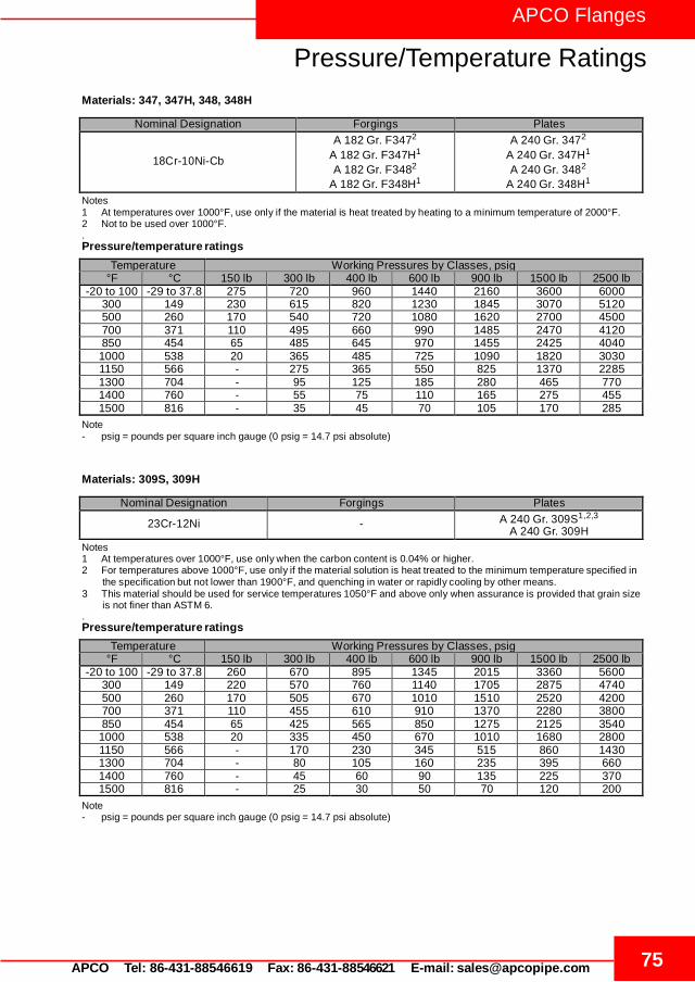
75 APCO Tel: 86-431-88546619 Fax: 86-431-88546621 E-mail: [email protected]
APCO Flanges
Pressure/Temperature Ratings
Materials: 347, 347H, 348, 348H
Nominal Designation Forgings Plates
18Cr-10Ni-Cb
A 182 Gr. F3472
A 182 Gr. F347H1
A 182 Gr. F3482
A 182 Gr. F348H1
A 240 Gr. 3472
A 240 Gr. 347H1
A 240 Gr. 3482
A 240 Gr. 348H1
Notes 1 At temperatures over 1000°F, use only if the material is heat treated by heating to a minimum temperature of 2000°F. 2 Not to be used over 1000°F. . Pressure/temperature ratings
Temperature Working Pressures by Classes, psig °F °C 150 lb 300 lb 400 lb 600 lb 900 lb 1500 lb 2500 lb
-20 to 100 -29 to 37.8 275 720 960 1440 2160 3600 6000 300 149 230 615 820 1230 1845 3070 5120 500 260 170 540 720 1080 1620 2700 4500 700 371 110 495 660 990 1485 2470 4120 850 454 65 485 645 970 1455 2425 4040 1000 538 20 365 485 725 1090 1820 3030 1150 566 - 275 365 550 825 1370 2285 1300 704 - 95 125 185 280 465 770 1400 760 - 55 75 110 165 275 455 1500 816 - 35 45 70 105 170 285
Note - psig = pounds per square inch gauge (0 psig = 14.7 psi absolute)
Materials: 309S, 309H
Nominal Designation Forgings Plates
23Cr-12Ni - A 240 Gr. 309S1,2,3 A 240 Gr. 309H
Notes 1 At temperatures over 1000°F, use only when the carbon content is 0.04% or higher. 2 For temperatures above 1000°F, use only if the material solution is heat treated to the minimum temperature specified in
the specification but not lower than 1900°F, and quenching in water or rapidly cooling by other means. 3 This material should be used for service temperatures 1050°F and above only when assurance is provided that grain size
is not finer than ASTM 6. . Pressure/temperature ratings
Temperature Working Pressures by Classes, psig °F °C 150 lb 300 lb 400 lb 600 lb 900 lb 1500 lb 2500 lb
-20 to 100 -29 to 37.8 260 670 895 1345 2015 3360 5600 300 149 220 570 760 1140 1705 2875 4740 500 260 170 505 670 1010 1510 2520 4200 700 371 110 455 610 910 1370 2280 3800 850 454 65 425 565 850 1275 2125 3540 1000 538 20 335 450 670 1010 1680 2800 1150 566 - 170 230 345 515 860 1430 1300 704 - 80 105 160 235 395 660 1400 760 - 45 60 90 135 225 370 1500 816 - 25 30 50 70 120 200
Note - psig = pounds per square inch gauge (0 psig = 14.7 psi absolute)

76 APCO Tel: 86-431-88546619 Fax: 86-431-88546621 E-mail: [email protected]
APCO Flanges
Pressure/Temperature Ratings
Materials: 310, 310S, 310H
Nominal Designation Forgings Plates
25Cr-20Ni A 182 Gr. F3101,3 A 240 Gr. 310S1,2,3
A 240 Gr. 310H Notes 1 At temperatures over 1000°F, use only when the carbon content is 0.04% or higher. 2 For temperatures above 1000°F, use only if the material is heat treated by heating it to a temperature of at least 1900°F
and quenching in water or rapidly cooling by other means. 3 Service temperatures of 1050°F and above should only be used when assurance is provided that grain size is not finer than
ASTM 6. . Pressure/temperature ratings
Temperature Working Pressures by Classes, psig °F °C 150 lb 300 lb 400 lb 600 lb 900 lb 1500 lb 2500 lb
-20 to 100 -29 to 37.8 260 670 895 1345 2015 3360 5600 300 149 220 570 760 1140 1705 2845 4740 500 260 170 505 675 1015 1520 2530 4220 700 371 110 455 610 910 1370 2280 3800 850 454 65 425 575 855 1280 2135 3560
1000 538 20 345 460 685 1030 1720 2865 1150 566 - 190 250 375 565 945 1570 1300 704 - 75 100 150 225 375 630 1400 760 - 45 60 90 135 225 370 1500 816 - 25 35 50 75 130 215
Note - psig = pounds per square inch gauge (0 psig = 14.7 psi absolute)
Materials: F44, F51, F53
Nominal Designation Forgings Plates 20Cr-18Ni-6Mo 22Cr-5Ni-3Mo-N 25Cr-7Ni-4Mo-N
A 182 Gr. F44 A 182 Gr. F511
A 182 Gr. F531
A 240 Gr. S31254 A 240 Gr. S318031
A 240 Gr. S327501
Note 1 This steel may become brittle after service at moderately elevated temperatures. Not to be used over 600°F.
Pressure/temperature ratings
Temperature Working Pressures by Classes, psig °F °C 150 lb 300 lb 400 lb 600 lb 900 lb 1500 lb 2500 lb
-20 to 100 -29 to 37.8 290 750 1000 1500 2250 3750 6250 300 149 230 665 885 1330 1995 3325 5540 500 260 170 575 770 1150 1730 2880 4800 700 371 110 540 725 1085 1625 2710 4520 750 399 95 530 710 1065 1595 2660 4430
Note - psig = pounds per square inch gauge (0 psig = 14.7 psi absolute)