apd power management system installation manual · · 2013-10-15apd power management system...
TRANSCRIPT

AlarmSaf 65A Industrial Way, Wilmington, MA 01887-3499, USA, Toll Free: 800-987-1050, Voice: 978-658-6717, Fax: 978-658-8638, www.alarmsaf.com
APD Power Management System Installation Manual
This Installation manual is made up of the following separate Installation Instructions for the Power Supplyand Power Distribution Module.
52-209 - Installation Instructions for CPS2 - CPS1000 - pp. 2-1952-254 - Installation Instructions for APD8(F)- p. 20-43
Model Numbers: Order Numbers:CPS800C-UL/CSA-APD8 02811CPS800C-UL/CSA-APD8F 02812CPS800C-UL/CSA-APD8X 02813CPS800C-UL/CSA-APD8FX 02814CPS800C-UL/CSA-APD16X 02815CPS800C-UL/CSA-APD16FX 02816
Model Numbers: Order Numbers:CPS1000C-UL/CSA-APD8 02817CPS1000C-UL/CSA-APD8F 02818CPS1000C-UL/CSA-APD8X 02819CPS1000C-UL/CSA-APD8FX 02820CPS1000C-UL/CSA-APD16X 02821CPS1000C-UL/CSA-APD16FX 02822

ALARMSAF
J1
DC1 DC2AC
CPS 800/1000
VOLTS6 12 24
J1J2 C C O
C O O
J2
JP2 JP3S1
J3
J1
J4
AC
CPS200/400
Model CPS2 - CPS1000Power Supply / Battery Charger
Operating and Installation Instructions52-209 Rev B.02

I. Warnings and Notices
WARNING - To reduce the risk of fire or electric shock, do not expose thisproduct to rain or moisture
WARNING - This installation and all servicing should be made by qualifiedservice personnel and should conform to all local codes
NOTICE - This equipment shall be installed in a manner which preventsunintentional operation from employees or other personnel working about thepremises, by falling objects, by building vibration and by similar causes
NOTICE - This equipment is not intended for use within the patient care areas ofa Health Care Facility
CPS2-CPS1000 Installation Instructions5/24/13
52-209 Rev B.02Page 2 of 18
AlarmSaf 65A Industrial Way, Wilmington, MA 01887 978 658 6717 www.alarmsaf.com

Table of ContentsSection PageI. Warnings and Notices 21 Introduction 4
2 Applicable Standards / Documents 5
3 System Overview 63.1 Electrical Ratings and Specifications 63.2 Terminal Descriptions and Electrical Ratings 73.3 AC Input Connection 83.4 Battery Terminals 83.5 DC1 Output Terminals 83.6 DC2 Output Terminals 93.7 FAI Input Terminals 93.8 Fault Reporting Terminals 93.9 Fusing 9
4 Installation 104.1 Mounting 104.2 Wiring 11
5 Operating the CPS 125.1 Setting the Jumpers 125.2 Visual Indicators 135.3 Troubleshooting 14
6 Specifications 156.1 Electrical Specifications 156.2 Temperature Specifications 156.3 Mechanical Specifications 15
Appendix A 16Using the FAI Input and DC2 Output 16
Appendix B 17Using the SB (Special Battery) Terminal 17
Appendix C 18Using the (Optional) APD8(F) 18
CPS2-CPS1000 Installation Instructions5/24/13
52-209 Rev B.02Page 3 of 18
AlarmSaf 65A Industrial Way, Wilmington, MA 01887 978 658 6717 www.alarmsaf.com

Section 1Introduction
The CPS line of power supplies provides a field selectable 12VDC or 24VDC at 2.5A to 10A(depending on model) using buck topology switching technology.
Features:Field-selectable output voltage of 12V or 24VDC - Specific models also provide a 6V settingUnits will charge a maximum 7AH to 18AH (depending on model) battery set within 48 hoursAll listed units employ full fault detection with dual Form-C relay outputsNon-listed units are optionally available with fault detection also with dual Form-C relayoutputsCabinet-level systems are optionally available with one or more APD8 or APD8F distributionboards. See www.alarmsaf.com for details.Fault conditions monitored include:
Low or missing ACHigh or low output / batteryReversed BatteryInternal Power Supply failure
Visual indicators include:AC Presence (Green) - Units with Fault Detection onlyDC OK (Green) - Units with Fault Detection onlyOne or two DC Output Present LEDs (Red)
CPS2-CPS1000 Installation Instructions5/24/13
52-209 Rev B.02Page 4 of 18
AlarmSaf 65A Industrial Way, Wilmington, MA 01887 978 658 6717 www.alarmsaf.com

Section 2Applicable Standards / Documents
NFPA StandardsNFPA 72 National Fire Alarm CodeNFPA 70 National Electrical CodeNFPA 731 Standard for the Installation of Electronic Premises Security Systems
UL and Canadian Standards (Applies to model numbers ending in “-UL/CSA” only)UL 294 Access Control System UnitsCSA C22.2
OtherApplicable Local and State Building CodesRequirements of the Local Authority Having Jurisdiction (LAHJ)
Product UseWhen installed in accordance with all standards listed in Section 2 of this document, the CPS lineprovides power for use with typical 12 or 24VDC devices as used in the access control or securityindustries such as, but not limited to, mag locks, door strikes, door holders, card readers,keypads, etc.
CPS2-CPS1000 Installation Instructions5/24/13
52-209 Rev B.02Page 5 of 18
AlarmSaf 65A Industrial Way, Wilmington, MA 01887 978 658 6717 www.alarmsaf.com

Section 3System Overview
3.1 Electrical Ratings and SpecificationsManufactured By
www.alarmsaf.comFax: 978 658 8638Wilmington, MA 01887Tel: 978 658 671765A Industrial WayTel: 800 987 1050AlarmSaf
Model Numbers and Electrical Ratings
Table 3.1YesYes14AH x 26.0A + 4.0A3.50A120VAC15x18x402906CPS640DX-UL/CSAYesYes14AH x 26.0A + 4.0A3.50A120VAC11x15x402905CPS640D-UL/CSAYesYes14AH x 24.0A + 4.0A3.00A120VAC15x18x402904CPS440DX-UL/CSAYesYes14AH x 24.0A + 4.0A3.00A120VAC11x15x402903CPS440D-UL/CSAYesYes14AH x 22.5A + 4.0A2.00A120VAC15x18x402902CPS240DX-UL/CSAYesYes14AH x 22.5A + 4.0A2.00A120VAC11x15x402901CPS240D-UL/CSA
YesYes18AH10.0A3.50A120VAC11x15x401363CPS1000C-UL/CSANoYes18AH10.0A3.50A120VAC11x15x400867CPS100CYesYes18AH8.0A3.00A120VAC11x15x401369CPS800C-UL/CSANoYes18AH8.0A3.00A120VAC11x15x400865CPS80CYesYes18AH6.0A2.50A120VAC11x15x401368CPS600C-UL/CSANoYes18AH6.0A2.50A120VAC11x15x400863CPS60CNoNo18AH6.0A2.50A120VAC11x15x400855CPS6CYesYes14AH4.0A Class 21.50A120VAC12x12x401366CPS400C-UL/CSANoYes14AH4.0A1.50A120VAC12x12x400861CPS40CNoNo14AH4.0A1.50A120VAC12x12x400856CPS4C-14NoNo14AH4.0A1.50A120VAC8x7x3.500853CPS4CYesYes7AH2.5A1.00A120VAC12x12x401364CPS200C-7-UL/CSAYesYes7AH2.5A Class 21.00A120VAC8x7x3.501365CPS200C-UL/CSANoYes7AH2.5A1.00A120VAC12x12x400859CPS20C-7NoYes7AH2.5A1.00A120VAC8x7x3.500858CPS20CNoNo7AH2.5A1.00A120VAC8x7x3.500851CPS2C
Note 3Yes18AH10.0ANote 3Note 328VACNone01367CPS1000-UL/CSANoYes18AH10.0A28V36028V360Note 2None00866CPS100
Note 3Yes18AH8.0ANote 3Note 328VACNone01375CPS800-UL/CSANoYes18AH8.0A28V36028V360Note 2None00864CPS80
Note 3Yes18AH6.0ANote 3Note 328VACNone01374CPS600-UL/CSANoYes18AH6.0AT24V5AT24V4ANote 2None00862CPS60NoNo18AH6.0AT24V5AT24V4ANote 2None00854CPS6
Note 3Yes14AH4.0A Class 2Note 3Note 328VACNone01373CPS400-UL/CSANoYes14AH4.0AT29V196T24V4ANote 2None00860CPS40NoNo14AH4.0AT29V196T24V4ANote 2None00852CPS4
Note 3Yes7AH2.5A Class 2Note 3Note 328VACNone01372CPS200-UL/CSANoYes7AH2.5AT29V120T24V40Note 2None00857CPS20NoNo7AH2.5AT29V120T24V40Note 2None00850CPS2
12/24V12V OnlyListed?
Fault/FAI/DC2/SB?(Note 5)
Max BatteryMax Output
Current(Note 4)
Max Input Current orTransformer Required.Input
VoltageEnclosure
OrderNumber
Model(Note 1)
Note 1 - Some of the above models are available with one or two APD8(F) Advanced Power Distribution modules - www.alarmsaf.com for detailsNote 2 - Minimum input AC voltage is 3V above the desired output voltage setting. Maximum transformer voltage is not to exceed 30VACNote 3 - This model is a UL recognized component. It is only approved for use as a replacement board using the existing transformer andenclosureNote 4 - Models which state “Class 2” next to the output current have Class 2 Power Limited DC OutputsNote 5 - Models marked “Yes” have Fault Outputs, an FAI Input, a DC2 Output, and an SB Terminal. Models marked “No” do not have thesefeatures.
CPS2-CPS1000 Installation Instructions5/24/13
52-209 Rev B.02Page 6 of 18
AlarmSaf 65A Industrial Way, Wilmington, MA 01887 978 658 6717 www.alarmsaf.com

3.2 CPS Board Terminal Descriptions and Electrical Ratings
AC Fault Relay CommonAC FAULT CAC Fault Relay Normally OpenAC FAULT NO
1 Amp at 24VDC (Resistive) - Contacts are labeled inthe non-powered (Fault) condition
AC Fault Relay Normally ClosedAC FAULT NCDC Fault Relay CommonDC FAULT C
DC Fault Relay Normally OpenDC FAULT NO1 Amp at 24VDC (Resistive) - Contacts are labeled in
the non-powered (Fault) condition
DC Fault Relay Normally ClosedDC FAULT NCTB4 - Fault Outputs - Units with Fault Outputs ONLY
DC2 Common Output - FAIControlled
DC2 OUT -
12VDC or 24VDC at full output current of supply - FAIControlled - See Table 3.1 and Appendix A.
DC2 Positive Output - FAI ControlledDC2 OUT +DC1 Common OutputDC1 OUT -
12VDC or 24VDC at full output current of supply - SeeTable 3.1 for ratings.
DC1 Positive OutputDC1 OUT +TB3 - DC Output (DC2 Present on Units with FAI Input ONLY)
FAIDry Contact Input - See Appendix AFire Alarm Input
FAITB2 - Fire Alarm Input - Units with FAI Input ONLY
Negative Battery ConnectionBAT -12VDC or 24VDC at 7AH - 18AH maximum - See
Table 3.1 for RatingsPositive Battery ConnectionBAT +
See Appendix B for details on the SB terminalSpecial Battery TerminalSBLVAC
28.2VAC - See Table 3.1 for RatingsLow voltage AC inputLVAC
TB1 - Low Voltage AC Input and Battery OutputRatingDescriptionTerminal / Connector
DC OUTPUTFUSE ATC-7.5
VOLTAGESELECT FOR
20/40/60200/400/600
VOLTAGESELECT FOR
80/100800/1000
J1
DC2FAILSAFE / FAILSECURE
SELECTAC FAULT
DC FAULT
DC SYSTEM ‘OK’
DC OUTPUT PRESENT
FAICONNECT
AC PRESENCE
LVACCONNECT TO
TRANSFORMER
SPECIALFUNCTION
BATTERYCONNECT
DC1OUTPUT
DC2OUTPUTDC OUTPUT PRESENT
VOLTAGE SELECT
AC PRESENCE
DCOUTPUTBATTERYCONNECT
LOW VOLTAGEAC CONNECT
Figure 3.2
Note: Wire should be sized appropriately for voltage drop and current carrying capability. Allterminals are labeled for polarity where appropriate.
CPS2-CPS1000 Installation Instructions5/24/13
52-209 Rev B.02Page 7 of 18
AlarmSaf 65A Industrial Way, Wilmington, MA 01887 978 658 6717 www.alarmsaf.com

3.3 AC Input Connection3.3.1 Board-Level Supplies
Board-level units are connected to an appropriate low-voltage AC supply voltage of a sufficientVA rating (See Table 3.1). The connection is made on TB1 at the terminals labeled “LVAC.”The phase of this connection is not important.
3.3.2 Cabinet-Level SuppliesCabinet-level supplies are supplied with a hardwired transformer of the correct voltage. Theconnections should be made as follows:
Black HotWhite NeutralGreen Earth Ground
Note - The Green or Green/Yellow earth ground wire should always be connected first ordisconnected last for safety.
Note - All wiring should be installed in accordance with (NEC760) NFPA70, NFPA72, and all localcode requirements. Power limited wiring requires that power limited and non-power limited wiringremain physically separated. All power limited circuits must remain at least one quarter inch ( ”)away from any non-power limited circuit wiring. All power limited circuit wiring must enter and exitthe cabinet through different knockouts than non-power limited wiring.
3.4 Battery TerminalsThe CPS has one set of battery terminals labeled BAT +/- which will charge a sealed lead acid /gel cell battery set for backup of the output voltage. The battery terminals are fuse protected.
Caution - Observe the polarity of the battery terminals with respect to the battery set or damageto the load, power supply, or battery set may occur.
Note - Series-connected batteries should always be of the same amphour capacity, age, andstate-of-charge to prevent battery / system damage.
Note - It is the responsibility of the installer to determine the minimum battery requirement for theparticular application in which the supply is being used. Backup batteries should be serviced atregular intervals as determined by local and/or national codes.
3.5 DC1 Output TerminalsThe DC1 output terminals provide a constant output of either 12VDC or 24VDC. See Section 5.1for additional information on output voltage selection on board-level units.
Caution - Observe the polarity of the output terminals with respect to the load or damage to theload may occur.
CPS2-CPS1000 Installation Instructions5/24/13
52-209 Rev B.02Page 8 of 18
AlarmSaf 65A Industrial Way, Wilmington, MA 01887 978 658 6717 www.alarmsaf.com

3.6 DC2 Output TerminalsThe DC2 output terminals provide a controlled output of either 12VDC or 24VDC. Control isprovided through the FAI input. The operation of the DC2 output is set by jumper S1. SeeAppendix A for more information on using the FAI Input and DC2 output.
Note - Not all models of CPS have a DC2 output.
Caution - Observe the polarity of the output terminals with respect to the load or damage to theload may occur.
3.7 FAI Input TerminalsThe FAI input accepts either a normally open or normally closed set of dry contacts to providecontrol to the DC2 output. The operation of the FAI input is set by jumper J1. See Appendix A formore information on using the FAI Input and DC2 output.
Note - Not all models of CPS have an FAI input - See Table 3.1 for details.
3.8 Fault Reporting TerminalsSome models of CPS have two integral sets of Form-C fault relay outputs. See Table 3.1 todetermine whether the Fault Outputs are present for a particular model number. Fault conditionsindicated include:
Low Output VoltageHigh Output VoltageLow Battery VoltageHigh Battery VoltageBlown Fuse (AC or Battery)Low or missing AC
NOTE - The CPS line of power supplies does NOT detect battery presence. If battery presencedetection is required, AlarmSaf also manufactures supplies with integral battery presencedetection.
The integral relay outputs provide fail-safe, Form-C relay outputs rated at 1A at 24VDC.Terminals are labeled in the unpowered (fault) state.
3.9 FusingSome models of CPS contain one replaceable fuse - the Battery Fuse. When replacing this fuse,only the equivalent type and rating are to be used. Battery Fuses are blade-type automotivefuses (ATC).
CPS2-CPS1000 Installation Instructions5/24/13
52-209 Rev B.02Page 9 of 18
AlarmSaf 65A Industrial Way, Wilmington, MA 01887 978 658 6717 www.alarmsaf.com

Section 4Installation
4.1 MountingThe CPS line is available in either board-level or cabinet level versions.
4.1.1 Mounting a Cabinet-Level SupplyIf the CPS is provided in a wall mount enclosure, use #8 hardware minimum in four locations.Use an appropriate fastening system for the mounting surface.
Cabinet Mounting:1. Mark and predrill two holes for the top keyhole mounting screws2. Install two fasteners in the mounting wall leaving screwheads protruding approximately
� inch3. Using the two upper keyholes, mount the cabinet over the two screws4. Mark the two lower holes, remove the cabinet and drill the lower mounting holes5. Mount the cabinet, install the remaining fasteners, and tighten all fasteners
BN
ABC
Figure 4.1.1
4.1.2 Mounting a Board-Level SupplyBoard-level, supplies can be mounted either with the provided double-sided tape or by usingnylon standoffs and hardware (not included). Replacement boards for a listed supply mustreuse the existing hardware to maintain the listing.
CPS2-CPS1000 Installation Instructions5/24/13
52-209 Rev B.02Page 10 of 18
AlarmSaf 65A Industrial Way, Wilmington, MA 01887 978 658 6717 www.alarmsaf.com
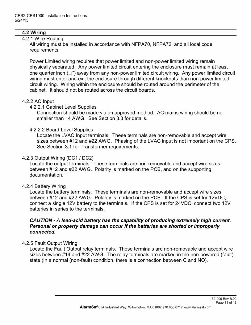
4.2 Wiring4.2.1 Wire Routing
All wiring must be installed in accordance with NFPA70, NFPA72, and all local coderequirements.
Power Limited wiring requires that power limited and non-power limited wiring remainphysically separated. Any power limited circuit entering the enclosure must remain at leastone quarter inch (�”) away from any non-power limited circuit wiring. Any power limited circuitwiring must enter and exit the enclosure through different knockouts than non-power limitedcircuit wiring. Wiring within the enclosure should be routed around the perimeter of thecabinet. It should not be routed across the circuit boards.
4.2.2 AC Input4.2.2.1 Cabinet Level Supplies
Connection should be made via an approved method. AC mains wiring should be nosmaller than 14 AWG. See Section 3.3 for details.
4.2.2.2 Board-Level SuppliesLocate the LVAC Input terminals. These terminals are non-removable and accept wiresizes between #12 and #22 AWG. Phasing of the LVAC input is not important on the CPS.See Section 3.1 for Transformer requirements.
4.2.3 Output Wiring (DC1 / DC2)Locate the output terminals. These terminals are non-removable and accept wire sizesbetween #12 and #22 AWG. Polarity is marked on the PCB, and on the supportingdocumentation.
4.2.4 Battery WiringLocate the battery terminals. These terminals are non-removable and accept wire sizesbetween #12 and #22 AWG. Polarity is marked on the PCB. If the CPS is set for 12VDC,connect a single 12V battery to the terminals. If the CPS is set for 24VDC, connect two 12Vbatteries in series to the terminals.
CAUTION - A lead-acid battery has the capability of producing extremely high current.Personal or property damage can occur if the batteries are shorted or improperlyconnected.
4.2.5 Fault Output WiringLocate the Fault Output relay terminals. These terminals are non-removable and accept wiresizes between #14 and #22 AWG. The relay terminals are marked in the non-powered (fault)state (In a normal (non-fault) condition, there is a connection between C and NO).
CPS2-CPS1000 Installation Instructions5/24/13
52-209 Rev B.02Page 11 of 18
AlarmSaf 65A Industrial Way, Wilmington, MA 01887 978 658 6717 www.alarmsaf.com

Section 5Operating the CPS
5.1 Setting the JumpersBefore powering a system containing a CPS, the jumpers should be set for proper operation. Besure to reference the proper section of the manual (5.1.1 or 5.1.2) for the model of CPS you areusing.
5.1.1 Units WITH Fault Relay Output
Fail-SafeSee Section 5.1.1.3DC2 OperationS1OffLeave Jumper OffNot UsedJ4
IntactIntact - Backup EnabledCut - Backup Disabled
DC2 Battery BackupJ2
Both ONBoth ON - 12VBoth OFF - 24V
Output voltageSetting
J1 & J3
DefaultSettingsDescriptionJumper
WARNING - BOTH voltage setting jumpers must be set for proper operation of the CPS. Failure toset both jumpers will result in damage to the CPS board.
5.1.1.1 Output Voltage Setting (J1 & J3)J1 and J3 control the output voltage setting of the CPS. With both jumpers ON, the outputvoltage will be 12VDC nominal. With both jumpers OFF, the output voltage will be 24VDC.BOTH jumpers must be set, or damage to the CPS will occur.
5.1.1.2 DC2 Battery Backup (J2)J2 is a wire jumper that controls whether or not the DC2 output is backed up by the standbybattery set. This is useful for installations that require maglocks to open upon AC power loss.Cutting this jumper removes the battery backup from the DC2 output. This jumper does notaffect the DC1 output.
5.1.1.3 DC2 Operation (S1)On units with Fault Relay Output, the DC2 output is the FAI controlled output of the powersupply. The S1 jumper determines the operation of the DC2 output when there is an FAI (FireAlarm Interface) input. The default setting on all units is FAIL-SAFE. Jumper positions are:
3 - 13 - 11 - 2
There is no power to the DC2 output untilan FAI input is received. DC2 remainspowered during the FAI event. Power isremoved from DC2 when the FAI input isremoved.
FAIL-SECURE
3 - 23 - 21 - 3
Power to the DC2 output is removed whenan FAI input is received. Power to the DC2output returns when the FAI input isremoved
FAIL-SAFE(DEFAULT)
CPS80/100 &CPS800/1000
CPS60 &CPS600
CPS20/40 &CPS200/400
S1 POSITION
DESCRIPTION
JUMPER S1 - DC2 OUTPUT SETTINGS
.
CPS2-CPS1000 Installation Instructions5/24/13
52-209 Rev B.02Page 12 of 18
AlarmSaf 65A Industrial Way, Wilmington, MA 01887 978 658 6717 www.alarmsaf.com

5.1.2 Units WITHOUT Fault Relay Output
OpenOpenN/AJ2OpenClosedN/AJ1
24V Output12V Output*6V OutputJumper
5.1.2.1 Output Voltage Setting (J1 & J2)J1 and J2 control the output voltage setting of the CPS. CPS models without Fault Relaysmay be set for 12VDC, or 24VDC output. Set the jumpers as shown in the table forthe desired output voltage.
5.2 Visual IndicatorsThe CPS contains one or four visual status indicators, depending on model. Models with faultoutputs have four visual indicators, while models without fault outputs only have one visualindicator.
5.2.1 AC (Green) - Units with Fault Outputs ONLYThis LED lights when Low Voltage AC is present.
CAUTION - Always check for AC presence with an AC volt meter before servicing
5.2.2 DC OK (Green) - Units with Fault Outputs ONLYThis LED lights when there is no trouble condition detected by the CPS. The LEDextinguishes under one of the fault conditions listed in Section 3.8.
5.2.3 DC (Red) - Models without Fault Outputs ONLYThis LED lights when output voltage is present at the DC Output terminals
5.2.4 DC1 / DC2 - Models with Fault Outputs ONLYThese LEDs light when output voltage is present on the DC1 and DC2 outputs respectively.The DC2 LED may switch on or off depending on the state of the FAI input and jumper S1
CPS2-CPS1000 Installation Instructions5/24/13
52-209 Rev B.02Page 13 of 18
AlarmSaf 65A Industrial Way, Wilmington, MA 01887 978 658 6717 www.alarmsaf.com
*Factory default

5.3 Troubleshooting
Contact AlarmSafInternal problem with CPS
Verify the presence of at least102VAC on the primary of theTransformer
Low or Missing AC
Verify that a good battery set of theproper voltage is connected to theCPS
Damaged, Incorrect, or MissingBattery Set
Verify that output current is less thanthe rated current
Excessive loading on output
Verify fuse is intact - Check wiringintegrity before replacing fuse
Blown battery fuse
The DC OK LED is extinguished,indicating a fault condition
Contact AlarmSafInternal problem with CPS
Verify that a good battery set of theproper voltage is connected to theCPS
Bad / Incorrect Battery Set
Verify presence of AC voltageAC trouble
Verify that output current is less thanrated current
Excessive loading on output
Verify proper jumper settingsIncorrect jumper settings
The output voltage of the CPS isincorrect or missing
SolutionPossible CauseCondition
CPS2-CPS1000 Installation Instructions5/24/13
52-209 Rev B.02Page 14 of 18
AlarmSaf 65A Industrial Way, Wilmington, MA 01887 978 658 6717 www.alarmsaf.com

Section 6Specifications
6.1 Electrical Specifications6.1.1 Input Voltage See Section 3.16.1.2 Input Power See Section 3.16.1.3 Output Voltage 12 or 24VDC Nominal - See Section 5.16.1.4 Output Current See Section 3.16.1.5 Maximum Battery Charger Capacity See Section 3.1
6.2 Temperature Specifications6.2.1 Ambient Temperature Range 0ºC to 49ºC (32ºF to 120ºF)6.2.2 Ambient Humidity 93% at 32 ºC (90ºF) Maximum
6.3 Mechanical SpecificationsAll dimensions in inches; all weights in pounds. Reference drawing below table for more details.
5.003.206.254.75CPS100 /1000
5.003.206.254.75CPS80 / 8005.003.205.754.25CPS60 / 6004.002.704.503.00CPS65.003.205.754.25CPS40 / 4005.003.205.754.25CPS20 / 2003.602.454.002.75CPS43.602.454.002.75CPS2
ApproximateBoard Weight
MountingLength (D)
MountingWidth (B)
HeightLength (C)Width (A)Model
CPS2-CPS1000 Installation Instructions5/24/13
52-209 Rev B.02Page 15 of 18
AlarmSaf 65A Industrial Way, Wilmington, MA 01887 978 658 6717 www.alarmsaf.com
0.60 LBS0.60 LBS1.25 LBS1.25 LBS1.25 LBS1.5 LBS1.5 LBS2.20 LBS
1.1251.501.502.252.1252.252.252.25
NOTE: ALL DIMENSIONS IN INCHES AND ARE APPROXIMATE
DC OUTPUTFUSE ATC-7.5
AB
C
D

Appendix AUsing the FAI Input and DC2 Output
Some models of CPS have an FAI input and a DC2 output, which is controlled by the FAI input.The FAI input may be activated by either a Normally Open or a Normally Closed contact, and theDC2 output can operate either as Fail-Safe of Fail-Secure by setting the S1 jumper appropriately(See Section 5.1).
The diagrams below show the common methods of using and wiring the FAI input and DC2output.
This diagram shows a systemwhich removes power from theDC2 output when the NCcontact on the FAI terminalsopens. Power returns when thecontact is opened.
If the NC contact was replacedwith an NO contact, the DC2output would normally beunpowered and the outputwould power up when the NOcontact closes
FAI NCRELAY
CPS600 SHOWNPOSITION JUMPER TO REMOVE POWER
ON OPEN OF FAI RELAY.REVIEW INSTRUCTIONS FOR SPECIFIC POSTION
OF JUMPER ON OTHER CPS UNITS
SYSTEMPOWER
MAGLOCK
This diagram shows a systemwhich removes power from theDC2 output when the NOcontact on the FAI terminalscloses. Power returns whenthe contact is opened.
If the NO contact was replacedwith an NC contact, the DC2output would normally beunpowered and the outputwould power up when the NCcontact opens.
FAI NORELAY
CPS600 SHOWNPOSITION JUMPER TO REMOVE POWER
ON CLOSURE OF FAI RELAY.REVIEW INSTRUCTIONS FOR SPECIFIC POSTION
OF JUMPER ON OTHER CPS UNITS
SYSTEMPOWER
MAGLOCK
CPS2-CPS1000 Installation Instructions5/24/13
52-209 Rev B.02Page 16 of 18
AlarmSaf 65A Industrial Way, Wilmington, MA 01887 978 658 6717 www.alarmsaf.com

Appendix BUsing the SB (Special Battery) Terminal
The SB Terminal allows the use of a single battery set in dual voltage systems utilizing multiplepower supplies. A 24V battery set is connected to the 24V power supply as normal, then alsoconnected to the 12V supply using the BAT- terminal and the SB terminal. Upon loss of ACpower, the 12V supply will then draw power from the 24V battery set and regulate it down to12VDC. See the diagram below for an example of wiring to the SB terminal.
CPS2-CPS1000 Installation Instructions5/24/13
52-209 Rev B.02Page 17 of 18
AlarmSaf 65A Industrial Way, Wilmington, MA 01887 978 658 6717 www.alarmsaf.com

Appendix CUsing the (Optional) APD8(F)
Some models of CPS are available with one or two APD8(F) Advanced Power Distribution modules. This Appendix provides a quick reference forjumper and switch settings for the APD8(F) and assumes a basic knowledge of the APD8(F) - for full APD8(F) instructions, refer to documentnumber 52-254, available from www.alarmsaf.com.
Input Configuration (S1-S8)Each input has one set of DIP switches, labeled S1 through S8. On each switch block, only the top six switches are used - the bottom twoare not used.
Note - Due to inconsistencies by the manufacturers of DIP switches in the labeling of switch numbers and ON and OFF positions, AlarmSafindicates switch settings visually and descriptively.Note - All switch settings shown below are indicated with the board positioned so that the edge of the board with two 8-pin terminal strips is atthe top, as shown in the diagram below
Left (Off / Open)Right (On / Closed)Left (Off / Open)Sixth SwitchRight (On / Closed)Right (On / Closed)Left (Off / Open)Fifth Switch
Left (Off / Open)Right (On / Closed)Left (Off / Open)Fourth SwitchLeft (Off / Open)Left (Off / Open)Right (On / Closed)Third Switch
Right (On / Closed)Left (Off / Open)Right (On / Closed)Second SwitchLeft (Off / Open)Left (Off / Open)Right (On / Closed)Top Switch
12V External TripPositive TripNegative Trip
Output Configuration (JP1-JP8)Each output has one jumper which may be set to one of three positions - C, D, or X. These three positions correspond to Constant Output,Disable Output on FAI, or Dry Contact output (X), respectively.
Power Source Setup (J1 and J2)These jumpers select whether the APD8(F) uses one source for control power and output power or separate sources.
With both jumpers IN, the APD8(F) uses the same source of power for both output power and internal relay & control power. Inputpower can be wired to either the “Lock Power” input or the “CTRL Power” input. This is the normal setting.
With both jumpers OUT, the APD8(F) requires separate control and output power. This setting is not normally required.
ISOLATED TRIP
FO
CV
XDCC D XXDCC D XXDCC D XXDCXDC
P
PI
P
N
NI
N
P
PI
P
N
NI
N N
NI
N
P
PI
P P
PI
P
N
NI
N N
NI
N
P
PI
P P
PI
P
N
NI
N N
NI
N
P
PI
P P
P
N
NI
N
NO C NC COM
NO C NC COM
OUT 1
COMNCCNO
NO C NC COM
COMNCCNO
NOC NC COM
COMNCCNO
NO C NC COM
FACPNO C NC COM
COMNCCNO NO C NC COM
COMNCCNO
NO C NC COM COMNCCNO
NO C NC COMCOMNCCNO
OUT 2 OUT 3 OUT 4 OUT 5 OUT 6 OUT 7 OUT 8
+IN 1- +IN 2- +IN 3- +IN 4- +IN 5- +IN 6- +IN 7- +IN 8-SET S1 THRU S8FOR EITHER POSITIVE,
NEGATIVE, OR
APD8
NO
C
NCNC
C
NO
+IN 1- +IN 2- +IN 3- +IN 4- +IN 5- +IN 6- +IN 7- +IN 8-
T+ T-
T+ T-
REPLACE FUSE ONLY WITH FUSE OF SAME TYPE AND RATING
J2J1
JP8JP7JP6JP5JP3JP2JP1 JP4
F1 F2 F3 F4 F5 F6 F7 F8
S1 S2 S3 S4 S5 S7 S8
+ +
+
+
+
-
-
CPS2-CPS1000 Installation Instructions5/24/13
52-209 Rev B.02Page 18 of 18
AlarmSaf 65A Industrial Way, Wilmington, MA 01887 978 658 6717 www.alarmsaf.com

ISOLATED TRIP
FO
CV
L0C
KC
TRL
XDCC D XXDCC D XXDCC D XXDCXDC
PPIP
NNIN
PPIP
NNIN N
NIN
PPIP P
PIP
NNIN N
NIN
PPIP P
PIP
NNIN N
NIN
PPIP P
P
NNIN
NO C NC COM
NO C NC COMOUT 1
COMNCCNO
NO C NC COM
COMNCCNO
NO C NC COM
COMNCCNO
NO C NC COMFACP
NO C NC COM
COMNCCNO NO C NC COM
COMNCCNO
NO C NC COM COMNCCNO
NO C NC COMCOMNCCNOOUT 2 OUT 3 OUT 4 OUT 5 OUT 6 OUT 7 OUT 8
+IN 1- +IN 2- +IN 3- +IN 4- +IN 5- +IN 6- +IN 7- +IN 8-SET S1 THRU S8FOR EITHER POSITIVE,
NEGATIVE, OR
APD8
NO
C
NC
FAC
P A
UX
NC
C
NO
L0C
KC
TRL
POW
ER
+IN 1- +IN 2- +IN 3- +IN 4- +IN 5- +IN 6- +IN 7- +IN 8-
T+ T-
Alar
mSa
fW
ilmin
gton
, MA
T+ T-
REPLACE FUSE ONLY WITH FUSE OF SAME TYPE AND RATING
J2J1
JP8JP7JP6JP5JP3JP2JP1 JP4
F1 F2 F3 F4 F5 F6 F7 F8
S1 S2 S3 S4 S5 S7 S8
TB6
+ +
+
- -
-
+
+
-
-
Model APD8(F)Eight-Zone Advanced Power Distribution
Operating and Installation Instructions52-254 Rev B01

I. Warnings and Notices
WARNING - To reduce the risk of fire or electric shock, do not expose this productto rain or moisture
WARNING - This installation and all servicing should be made by qualified servicepersonnel and should conform to all local codes
NOTICE - This equipment shall be installed in a manner which preventsunintentional operation from employees or other personnel working about thepremesis, by falling objects, by building vibration and by similar causes
NOTICE - This equipment is not intended for use within the patient care areas of aHealth Care Facility
Symbol Definitions
� WARNING - Read the instruction manual to avoid personal injury or
property damage
� WARNING - Risk of electric shock. Service to be performed by a qualified
service person
APD8(F) Installation Instructions10/9/2007, 12:19:29 PM
Page 2 of 24AlarmSaf 65A Industrial Way, Wilmington, MA 01887 978 658 6717 www.alarmsaf.com
52-254 Rev B01

Table of ContentsSection PageI. Warnings and Notices 21 Introduction 4
2 Applicable Standards / Documents 5
3 System Overview 63.1 Electrical Ratings and Specifications 63.2 Connector Descriptions and Electrical Ratings 73.3 Control Power and Lock Power Input Connections 83.4 Zone Inputs 93.5 Zone Outputs 93.6 FACP Input 103.7 FACP AUX Output 103.8 Fusing 11
4 Installation 124.1 Mounting 124.2 Wiring 13
5 Operating the APD8(F) 145.1 Power Separation Jumper Settings 145.2 Zone Input Configuration Switch Settings 145.3 Output Configuration Jumper Settings 155.4 Visual Indicators 155.5 Troubleshooting 16
6 Specifications 176.1 Electrical Specifications 176.2 Temperature Specifications 176.3 Mechanical Specifications 17
Appendix AConfiguring the Zone Inputs For Any Application 18
Appendix BUsing The Zone Outputs 20
Appendix CUsing the FACP Input and FACP AUX Output Terminals 21
Appendix DSample Applications 22
APD8(F) Installation Instructions10/9/2007, 12:19:29 PM
Page 3 of 24AlarmSaf 65A Industrial Way, Wilmington, MA 01887 978 658 6717 www.alarmsaf.com
52-254 Rev B01

Section 1Introduction
The APD8(F) is an access control power distribution system providing eight relay controlled,individually protected outputs. The ADP8 provides Class-2 power limited outputs via PTC protection,while the APD8F uses fuse protected outputs. Either system can be operated from 12V or 24V AC orDC and features independently programmable outputs, a variety of input option modes, Fire AlarmInterface and visual status indication.
Systems Integrator applications include mag lock and door strike control, reader power, request toexit device power, and system power. The diversity, flexibility and level of system isolation provided bythe APD8(F) make this unit a universal toolbox for access control applications.
Eight outputs - each individually programmable for fail-safe, fail-secure, form-C dry contact,continuous output voltage, and FAI controlledEight inputs - each individually programmable for negative trip, positive trip, open collector / drycontact trip, or isolated tripFire Alarm Interface - latching or non-latchingAvailable with Class-2 Power Limited outputsOutput voltage can be isolated from control voltageVisual status indication
Input Activation (Red)Control Voltage Present (Green)FAI Status (Red)
Removable field wiring terminal strips
APD8(F) Installation Instructions10/9/2007, 12:19:29 PM
Page 4 of 24AlarmSaf 65A Industrial Way, Wilmington, MA 01887 978 658 6717 www.alarmsaf.com
52-254 Rev B01

Section 2Applicable Standards / Documents
NFPA StandardsNFPA 72 National Fire Alarm CodeNFPA 70 National Electrical CodeNFPA 731 Standard for the Installation of Electronic Premises Security Systems
US StandardsUL 294 Access Control System Units
Canadian StandardsCAN/CSA-C22.2 No. 107.1-01 General Use Power Supplies
OtherApplicable Local and State Building CodesRequirements of the Local Authority Having Jurisdiction (LAHJ)
APD8(F) Installation Instructions10/9/2007, 12:19:29 PM
Page 5 of 24AlarmSaf 65A Industrial Way, Wilmington, MA 01887 978 658 6717 www.alarmsaf.com
52-254 Rev B01

Section 3System Overview
3.1 Electrical Ratings and SpecificationsManufactured By
www.alarmsaf.comFax: 978 658 8638Wilmington, MA 01887Tel: 978 658 671765A Industrial WayTel: 800 987 1050AlarmSaf
Model Numbers (Board-Level)APD8, APD8F
Electrical Ratings
0.01A @ 24VDCFAI Trip Current0.03A per inputInput Trip CurrentDependant on input voltageZone Output VoltageAPD8 - 1.6A maximum ; APD8F - 3.0A maximum Zone Output Current8A maximum output current or rating of power source - whichever is lessTotal Output Current0.4A@12VDC/0.2A@24VDC maximum control current + 8A maximum output currentInput Power10 - 30V AC or DCInput Voltage
Product UseWhen installed in accordance with all standards listed in Section 2 of this document, the APD8(F)provides power distribution for use with typical 12 or 24VDC devices used in the access control orsecurity industries such as, but not limited to, mag locks, door strikes, door holders, card readers,keypads, etc.
APD8(F) Installation Instructions10/9/2007, 12:19:29 PM
Page 6 of 24AlarmSaf 65A Industrial Way, Wilmington, MA 01887 978 658 6717 www.alarmsaf.com
52-254 Rev B01
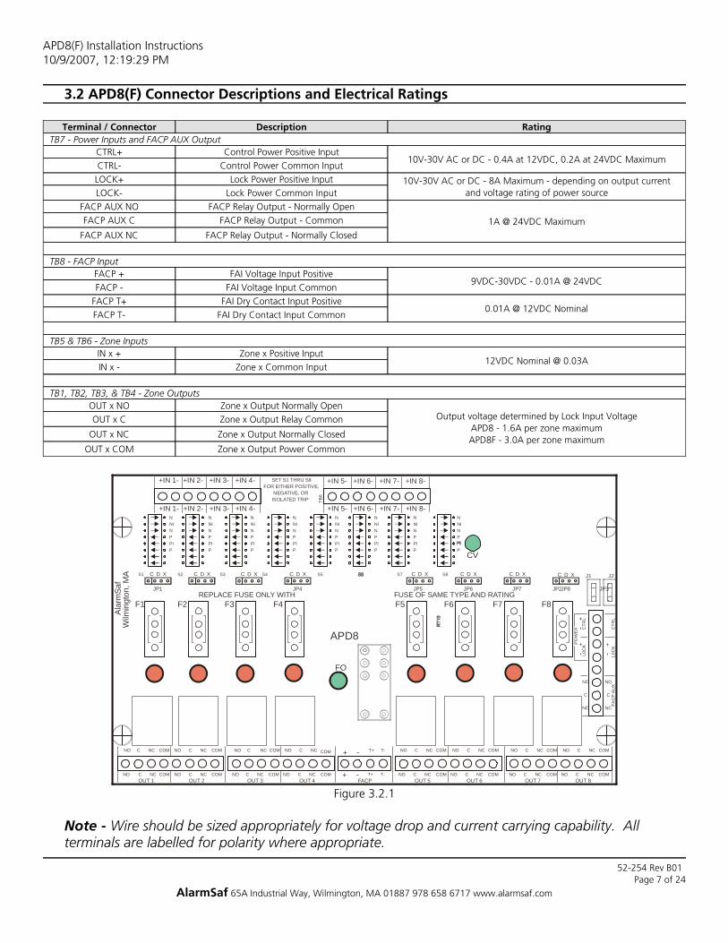
3.2 APD8(F) Connector Descriptions and Electrical Ratings
Zone x Output Power CommonOUT x COM
Zone x Output Normally ClosedOUT x NC
Zone x Output Relay CommonOUT x C Output voltage determined by Lock Input VoltageAPD8 - 1.6A per zone maximumAPD8F - 3.0A per zone maximum
Zone x Output Normally OpenOUT x NOTB1, TB2, TB3, & TB4 - Zone Outputs
Zone x Common InputIN x -12VDC Nominal @ 0.03A
Zone x Positive InputIN x +TB5 & TB6 - Zone Inputs
FAI Dry Contact Input CommonFACP T-0.01A @ 12VDC Nominal
FAI Dry Contact Input PositiveFACP T+FAI Voltage Input CommonFACP -
9VDC-30VDC - 0.01A @ 24VDCFAI Voltage Input PositiveFACP +
TB8 - FACP Input
FACP Relay Output - Normally ClosedFACP AUX NC
FACP Relay Output - CommonFACP AUX C 1A @ 24VDC Maximum
FACP Relay Output - Normally OpenFACP AUX NOLock Power Common InputLOCK-
10V-30V AC or DC - 8A Maximum - depending on output currentand voltage rating of power source
Lock Power Positive InputLOCK+Control Power Common InputCTRL-
10V-30V AC or DC - 0.4A at 12VDC, 0.2A at 24VDC MaximumControl Power Positive InputCTRL+
TB7 - Power Inputs and FACP AUX OutputRatingDescriptionTerminal / Connector
Figure 3.2.1
ISOLATED TRIP
FO
CV
L0C
KC
TRL
XDCC D XXDCC D XXDCC D XXDCXDC
PPIP
NNIN
PPIP
NNIN N
NIN
PPIP P
PIP
NNIN N
NIN
PPIP P
PIP
NNIN N
NIN
PPIP P
P
NNIN
NO C NC COM
NO C NC COMOUT 1
COMNCCNO
NO C NC COM
COMNCCNO
NO C NC COM
COMNCCNO
NO C NC COMFACP
NO C NC COM
COMNCCNO NO C NC COM
COMNCCNO
NO C NC COM COMNCCNO
NO C NC COMCOMNCCNOOUT 2 OUT 3 OUT 4 OUT 5 OUT 6 OUT 7 OUT 8
+IN 1- +IN 2- +IN 3- +IN 4- +IN 5- +IN 6- +IN 7- +IN 8-SET S1 THRU S8FOR EITHER POSITIVE,
NEGATIVE, OR
APD8
NO
C
NC
FAC
P A
UX
NC
C
NO
L0C
KC
TRL
POW
ER
+IN 1- +IN 2- +IN 3- +IN 4- +IN 5- +IN 6- +IN 7- +IN 8-
T+ T-
Alar
mSa
fW
ilmin
gton
, MA
T+ T-
REPLACE FUSE ONLY WITH FUSE OF SAME TYPE AND RATING
J2J1
JP8JP7JP6JP5 JP3JP2JP1 JP4
F1 F2 F3 F4 F5 F6 F7 F8
S1 S2 S3 S4 S5 S7 S8
TB6
+ +
+
- -
-
+
+
-
-
Note - Wire should be sized appropriately for voltage drop and current carrying capability. Allterminals are labelled for polarity where appropriate.
APD8(F) Installation Instructions10/9/2007, 12:19:29 PM
Page 7 of 24AlarmSaf 65A Industrial Way, Wilmington, MA 01887 978 658 6717 www.alarmsaf.com
52-254 Rev B01

3.3 Control Power and Lock Power Input ConnectionsThe APD8(F) has two separate power inputs - a control power input, and a lock power input. Usingtwo separate power inputs allows total separation of lock and control power sources. Typically, this isnot required, and jumpers J1 and J2 should remain in. See Section 5.1 for more information onconfiguring the APD8(F) for using separate power inputs.
Note - If J1 and J2 are out, BOTH power inputs must be wired to a power source. If J1 and J2 are inplace, either the control input or the power input may be used.Note - If J1 and/or J2 are missing, the control power and lock power inputs can be connectedtogether with wire jumpers if isolated power sources are not required.
3.3.1 Control Power InputIf J1 and J2 are removed, this input provides power to the internal relays and related circuitry ofthe APD8(F). The Control Power common is tied to the zone input common connections (unlessthe zone input is set as an insolated input). If J1 and J2 are removed, the Control Power input orZone Inputs have NO connection to the Lock Power input or the Zone Outputs.
3.3.2 Lock Power InputIf J1 and J2 are removed, this input provides power to the zone outputs of the APD8(F). The LockPower common is tied to the zone output common connections. If J1 and J2 are removed, theLock Power input or Zone Outputs have NO connection to the Control Power input or ZoneInputs.
Note - All wiring should be installed in accordance with (NEC760) NFPA70, NFPA72, and all localcode requirements. Power limited wiring requires that power limited and non-power limited wiringremain physically separated. All power limited circuits must remain at least one quarter inch (¼”)away from any non-power limited circuit wiring. All power limited circuit wiring must enter and exitthe cabinet through different knockouts than non-power limited wiring.
Fig. 3.3.1
~ ~
SYSTEM / CONTROL POWERISOLATION JUMPERS
CONTROL POWERINPUT VOLTAGE TERMINALS
LOCK POWERINPUT VOLTAGE TERMINALS
FACP AUXILIARYRELAY TERMINALS
~ ~
APD8(F) Installation Instructions10/9/2007, 12:19:29 PM
Page 8 of 24AlarmSaf 65A Industrial Way, Wilmington, MA 01887 978 658 6717 www.alarmsaf.com
52-254 Rev B01

3.4 Zone InputsEach Zone Output has a corresponding Zone Input. Each Zone Input provides on/off control for itsassociated output. Inputs are programmable for a variety of input types, including:
Open Collector InputIsolated Voltage TripNon-Isolated Positive TripNon-Isolated Negative TripNormally Closed Dry Contact - Negative SwitchingNormally Open Dry Contact - Negative SwitchingNormally Closed Dry Contact - Positive SwitchingNormally Open Dry Contact - Positive Switching
See Appendix A for specific information and example wiring diagrams for connecting the ZoneInputs.
3.5 Zone OutputsEach Zone Output of the APD8(F) can be used as a dry contact output, or as either a fail-safe orfail-secure voltage output. Jumpers JP1 through JP8 select the type of output for each zone (seeSection 5.1 for jumper information). See Appendix B for more information on the Zone Outputs.
3.5.1 If the Zone Output is configured as a dry contact output, the following connections apply:NO Normally Open relay contactC Relay CommonNC Normally Closed relay contact
3.5.2 If the Zone Output is configured as a voltage output, the following connections apply:NO Outputs voltage when the zone relay is activeC Always outputs voltage, regardless of relay conditionNC Outputs voltage when the zone relay is incativeCOM This terminal is the DC common associated with the output
Fig. 3.4
~ ~~ ~
INPUT ZONETRIP TERMINALS
OUTPUT RELAYSTATUS
OUTPUT ZONETERMINALS
APD8(F) Installation Instructions10/9/2007, 12:19:29 PM
Page 9 of 24AlarmSaf 65A Industrial Way, Wilmington, MA 01887 978 658 6717 www.alarmsaf.com
52-254 Rev B01

3.6 FACP InputThe APD8(F) has two FAI inputs, one which accepts a voltage input, and one that accepts a drycontact input. Consult the appropriate section below for Terminal Connections for the type ofconnection being used. See Appendix C for more information and specific wiring diagrams for theFACP Input.
3.6.1 Voltage FACP InputFACP + FACP Input PositiveFACP - FACP Input Common
3.6.2 Dry Contact FACP InputFACP T+ One leg of the FACP Dry Contact Input (This terminal is positive with respect
to DC Common)FACP T- The other leg of the FACP Dry Contact Input
NOTE - If the APD8(F) is being used with a power supply which has its own FAI Input, the supply’sFAI input may be used to control the APD8(F) board. See Appendix D for more information.
3.7 FACP AUX OutputThe FACP AUX output is a relay output which follows the FACP Input state. Typically, this output isused to activate the FACP Input on additional APD8(F) boards. See Appendix C and Appendix D forwiring details.
Fig. 3.6
~ ~ ~ ~FIRE ALARM
INPUT INDICATOR
FIRE ALARM OVER RIDETRIP TERMINALS
APD8(F) Installation Instructions10/9/2007, 12:19:29 PM
Page 10 of 24AlarmSaf 65A Industrial Way, Wilmington, MA 01887 978 658 6717 www.alarmsaf.com
52-254 Rev B01

3.8 FusingThe APD8F contains eight replacable fuses - one for each output zone. When replacing these fuses,only the equivalent type and rating are to be used. The APD8F utilizes commonly availableautomotive blade-type fuses (Type ATC). All fuses are rated at 3A (ATC-3).
Only the APD8F contains fuses. The APD8 uses output PTCs.
Fig. 3.8
ISOLATED TRIP
FO
CV
L0C
KC
TRL
XDCC D XXDCC D XXDCC D XXDCXDC
PPIP
NNIN
PPIP
NNIN N
NIN
PPIP P
PIP
NNIN N
NIN
PPIP P
PIP
NNIN N
NIN
PPIP P
P
NNIN
NO C NC COM
NO C NC COMOUT 1
COMNCCNO
NO C NC COM
COMNCCNO
NO C NC COM
COMNCCNO
NO C NC COMFACP
NO C NC COM
COMNCCNO NO C NC COM
COMNCCNO
NO C NC COM COMNCCNO
NO C NC COMCOMNCCNOOUT 2 OUT 3 OUT 4 OUT 5 OUT 6 OUT 7 OUT 8
+IN 1- +IN 2- +IN 3- +IN 4- +IN 5- +IN 6- +IN 7- +IN 8-SET S1 THRU S8FOR EITHER POSITIVE,
NEGATIVE, OR
APD8
NO
C
NC
FAC
P AU
X
NC
C
NO
L0C
KC
TRL
PO
WER
+IN 1- +IN 2- +IN 3- +IN 4- +IN 5- +IN 6- +IN 7- +IN 8-
T+ T-
Alar
mSa
fW
ilmin
gton
, MA
T+ T-
REPLACE FUSE ONLY WITH FUSE OF SAME TYPE AND RATING
J2J1
JP8JP7JP6JP5JP3JP2JP1 JP4
F1 F2 F3 F4 F5 F6 F7 F8
S1 S2 S3 S4 S5 S7 S8TB
6
+ +
+
- -
-
+
+
-
-
APD8(F) Installation Instructions10/9/2007, 12:19:29 PM
Page 11 of 24AlarmSaf 65A Industrial Way, Wilmington, MA 01887 978 658 6717 www.alarmsaf.com
52-254 Rev B01

Section 4Installation
4.1 MountingThe APD8(F) line is available in either board-level or cabinet level versions.
NOTE - For UL compliance, if the APD8(F) is mounted in an unprotected area, a Tamper Switch mustbe used.
4.1.1 Mounting a Cabinet-Level VersionIf the APD8(F) is provided in a wall mount enclosure, use #8 hardware minimum in four locations.Use an appropriate fastening system for the mounting surface.
Cabinet Mounting:1. Mark and predrill two holes for the top keyhole mounting screws2. Install two fasteners in the mounting wall leaving screwheads protruding approximately ¼
inch3. Using the two upper keyholes, mount the cabinet over the two screws4. Mark the two lower holes, remove the cabinet and drill the lower mounting holes5. Mount the cabinet, install the remaining fasteners, and tighten all fasteners
BN
ABC
Figure 4.1.1
4.1.2 Mounting a Board-Level VersionBoard-level units can be mounted either with the provided double-sided tape or by using nylonstandoffs and hardware (not included). Replacement boards for a listed unit must reuse theexisting hardware to maintain the listing.
APD8(F) Installation Instructions10/9/2007, 12:19:29 PM
Page 12 of 24AlarmSaf 65A Industrial Way, Wilmington, MA 01887 978 658 6717 www.alarmsaf.com
52-254 Rev B01

4.2 Wiring4.2.1 Wire Routing
All wiring must be installed in accordance with NFPA70, NFPA72, and all local code requirements.
Power Limited wiring requires that power limited and non-power limited wiring remain physicallyseparated. Any power limited circuit entering the enclosure must remain at least one quarter inch(¼”) away from any non-power limited circuit wiring. Any power limited circuit wiring must enterand exit the enclosure through different knockouts than non-power limited circuit wiring. Wiringwithin the enclosure should be routed around the perimeter of the cabinet. It should not berouted across the circuit boards.
4.2.2 Control and Lock Power InputsLocate the power input terminal block (TB7) and remove the terminal block from the header.Connect one or both power inputs as appropriate for the settings of J1 and J2 (See Sections 3.3and 5.1). Power input wiring should be sized appropriately for the total current draw from theoutputs of the APD8(F). See Section 3.3 for details. Replace the terminal block on the header.
4.2.3 Zone Input WiringLocate the terminal block for the zone input to be wired and remove the terminal block from theheader. Connect the input in the manner appropriate for the type of input signal being applied.See section 3.4 and Appendix A for more information. Replace the terminal block on the header.
4.2.4 Zone Output WiringLocate the terminal block for the zone output to be wired and remove the terminal block from theheader. Connect the output in the manner appropriate for the application. See section 3.5 andAppendix B for more information. Zone Output wiring should be sized appropriately for the totalcurrent draw from the output. Replace the terminal block on the header.
4.2.5 FACP InputLocate the FACP Input terminal block (TB8) and remove the terminal block from the header.Connect the proper input in the manner appropriate for the type of input signal being applied.See Section 3.6 and Appendix C for more information. Replace the terminal block on the header.
4.2.6 FACP AUX OutputLocate the FACP AUX Output terminal block (TB7) and remove the terminal block from theheader. Connect the FACP AUX Output as needed. See Section 3.7, Appendix C, and AppendixD for more information. Replace the terminal block on the header.
APD8(F) Installation Instructions10/9/2007, 12:19:29 PM
Page 13 of 24AlarmSaf 65A Industrial Way, Wilmington, MA 01887 978 658 6717 www.alarmsaf.com
52-254 Rev B01

Section 5Operating the APD8(F)
5.1 Power Separation Jumper SettingsThe APD8(F) gives the installer the ability to electrically isolate the Control power from the ZoneOutput power. This can be helpful in installations where noise-sensitive devices would be affected bylock noise.
To isolate the LOCK power input from the CTRL power input, jumpers J1 and J2 must BOTH beremoved.
Note - If J1 and J2 are out, BOTH power inputs must be wired to a power source. If J1 and J2 are inplace, either the control input or the power input may be used.Note - If J1 and/or J2 are missing, the control power and lock power inputs can be connectedtogether with wire jumpers if power isolation is not required.
5.2 Zone Input Configuration Switch SettingsEach zone of the APD8(F) has a set of DIP switches associated with its input. These switchesconfigure the input for use with a variety of signal types, however three basic configurations willcover a majority of applications. See Appendix A for information on configuring additional inputtypes.
Note - Only switches 1 through 6 are used for each input - switches 7 & 8 are unused.
Note - The factory configuration of these switches (Negative Trip Mode) should work for mostapplications.
5.2.1 Negative Trip ModeNegative Trip Mode will cover applications including Dry Contact (NO or NC) and Open Collector(including Casi-Rusco). To set the APD8(F) for Negative Trip Mode, Switches 1, 2, and 3 should beON (Closed), and all other switches should be OFF (Open).
5.2.2 Positive Trip ModePositive Trip Mode covers applications where a positive voltage is applied to the input foractivation. To set the APD8(F) for Positive Trip Mode, Switches 4, 5, and 6 should be ON (Closed),and all other switches should be OFF (Open).
5.2.3 External 12VDC Trip (Isolated)External Trip Mode covers applications with a completely isolated 12V source as an activationsource. The source may or may not be common-grounded with the rest of the system. To set theAPD8(F) for External Trip Mode, Switches 2 and 5 should be ON (Closed), and all other switchesshould be OFF (Open).
APD8(F) Installation Instructions10/9/2007, 12:19:29 PM
Page 14 of 24AlarmSaf 65A Industrial Way, Wilmington, MA 01887 978 658 6717 www.alarmsaf.com
52-254 Rev B01
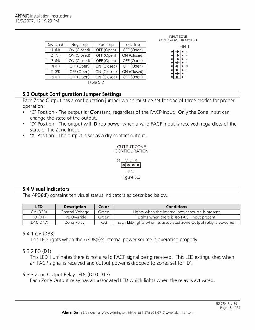
Table 5.2OFF (Open)ON (Closed)OFF (Open)6 (P)ON (Closed)ON (Closed)OFF (Open)5 (PI)OFF (Open)ON (Closed)OFF (Open)4 (P)OFF (Open)OFF (Open)ON (Closed)3 (N)ON (Closed)OFF (Open)ON (Closed)2 (NI)OFF (Open)OFF (Open)ON (Closed)1 (N)
Ext. TripPos. TripNeg. TripSwitch #
5.3 Output Configuration Jumper SettingsEach Zone Output has a configuration jumper which must be set for one of three modes for properoperation.
‘C’ Position - The output is ‘C’onstant, regardless of the FACP input. Only the Zone Input canchange the state of the output.‘D’ Position - The output will ‘D’rop power when a valid FACP input is received, regardless of thestate of the Zone Input.‘X’ Position - The output is set as a dry contact output.
Figure 5.3
XDC
JP1
S1
OUTPUT ZONECONFIGURATION
5.4 Visual IndicatorsThe APD8(F) contains ten visual status indicators as described below.
Each LED lights when its associated Zone Output relay is powered.RedZone Relay(D10-D17)Lights when there is no FACP input presentGreenFire OverrideFO (D1)
Lights when the internal power source is presentGreenControl VoltageCV (D33)ConditionsColorDescriptionLED
5.4.1 CV (D33)This LED lights when the APD8(F)’s internal power source is operating properly.
5.3.2 FO (D1)This LED illuminates there is not a valid FACP signal being received. This LED extinguishes whenan FACP signal is received and output power is dropped to zones set for ‘D’.
5.3.3 Zone Output Relay LEDs (D10-D17)Each Zone Output relay has an associated LED which lights when the relay is activated.
APD8(F) Installation Instructions10/9/2007, 12:19:29 PM
Page 15 of 24AlarmSaf 65A Industrial Way, Wilmington, MA 01887 978 658 6717 www.alarmsaf.com
PPIP
NNIN
+IN 1-
INPUT ZONECONFIGURATION SWITCH
52-254 Rev B01

5.5 Troubleshooting
Verify the Zone Output wiringZone Output wired incorrectlyVerify the FACP Input configurationFACP Input wired incorrectly
See Section 5.3Output Configuration Jumper set
incorrectlyOutput not dropping power on aFACP input
Contact AlarmSafOther Problem
Verify that the FACP input is notactivated.
FACP Input active
Verify output integrity and replacefuse, or remove output load to reset
PTC.Blown Fuse / Tripped PTC
See Section 5.3Output Configuration Jumper set
incorrectly
Verify the output is configuredproperly
Zone Output wired incorrectly
Verify the input is configured properlyZone Input in the wrong state
Verify power is present on the powerinput terminals. If J1 and J2 are
removed, BOTH power inputs mustbe powered.
No power input
See Section 5.1J1 and J2 set incorrectly
No power on output(s)
SolutionPossible CauseCondition
APD8(F) Installation Instructions10/9/2007, 12:19:29 PM
Page 16 of 24AlarmSaf 65A Industrial Way, Wilmington, MA 01887 978 658 6717 www.alarmsaf.com
52-254 Rev B01

Section 6Specifications
6.1 Electrical Specifications6.1.1 Input Voltage 10-30V AC or DC6.1.2 Input Power 0.4A@12VDC / 0.2A@24VDC maximum control
current + 8A maximum output current6.1.3 Output Voltage Dependent on Input Voltage6.1.4 Total Output Current 8A Maximum6.1.5 Zone Output Current APD8 - 1.6A Maximum
APD8F - 3.0A Maximum6.1.6 Input Trip Current 0.03A per input6.1.7 FAI Trip Current 0.01A at 24VDC
6.2 Temperature Specifications6.2.1 Ambient Temperature Range 0ºC to 49ºC (32ºF to 120ºF)6.2.2 Ambient Humidity 93% at 32ºC (90ºF) Maximum
6.3 Mechanical Specifications6.3.1 Weight (PCB Only) 0.70lbs.6.3.2 Size (PCB Only) 7.75”L x 4.75”W x 1.25”H Max.6.3.3 CAD Drawing
Figure 6.3.1
ISOLATED TRIP
FO
CV
L0C
KC
TRL
XDCC D XXDCC D XXDCC D XXDCXDC
PPIP
NNIN
PPIP
NNIN N
NIN
PPIP P
PIP
NNIN N
NIN
PPIP P
PIP
NNIN N
NIN
PPIP P
P
NNIN
NO C NC COM
NO C NC COMOUT 1
COMNCCNO
NO C NC COM
COMNCCNO
NO C NC COM
COMNCCNO
NO C NC COMFACP
NO C NC COM
COMNCCNO NO C NC COM
COMNCCNO
NO C NC COM COMNCCNO
NO C NC COMCOMNCCNOOUT 2 OUT 3 OUT 4 OUT 5 OUT 6 OUT 7 OUT 8
+IN 1- +IN 2- +IN 3- +IN 4- +IN 5- +IN 6- +IN 7- +IN 8-SET S1 THRU S8FOR EITHER POSITIVE,
NEGATIVE, OR
APD8
NO
C
NC
FAC
P A
UX
NC
C
NO
L0C
KC
TRL
PO
WER
+IN 1- +IN 2- +IN 3- +IN 4- +IN 5- +IN 6- +IN 7- +IN 8-
T+ T-
Alar
mSa
fW
ilmin
gton
, MA
T+ T-
REPLACE FUSE ONLY WITH FUSE OF SAME TYPE AND RATING
J2J1
JP8JP7JP6JP5 JP3JP2JP1 JP4
F1 F2 F3 F4 F5 F6 F7 F8
S1 S2 S3 S4 S5 S7 S8
TB6
+ +
+
- -
-
+
+
-
-
7.45"
7.75"
3.20
"
4.75
"
APD8(F) Installation Instructions10/9/2007, 12:19:29 PM
Page 17 of 24AlarmSaf 65A Industrial Way, Wilmington, MA 01887 978 658 6717 www.alarmsaf.com
52-254 Rev B01

Appendix AConfiguring The Zone Inputs For Any Application
Each zone of the APD8(F) has a set of DIP switches associated with its input. These switches configure the input for usewith a variety of signal types, including:
Open Collector InputIsolated Voltage TripNon-Isolated Positive TripNon-Isolated Negative TripNormally Closed Dry Contact - Negative SwitchingNormally Open Dry Contact - Negative SwitchingNormally Closed Dry Contact - Positive SwitchingNormally Open Dry Contact - Positive Switching
Note - Only switches one through 6 are used for each input - switches 7 & 8 are unused.
Off (Open)Off (Open)On (Closed)Off (Open)Off (Open)On (Closed)Off (Open)On (Closed)Switch 6Off (Open)On (Closed)On (Closed)Off (OpenOff (Open)On (Closed)Off (Open)On (Closed)Switch 5Off (Open)Off (Open)On (Closed)Off (Open)Off (Open)On (Closed)Off (Open)On (Closed)Switch 4On (Closed)Off (Open)Off (Open)On (Closed)On (Closed)Off (Open)On (Closed)Off (Open)Switch 3On (Closed)On (Closed)Off (Open)On (Closed)On (Closed)Off (Open)On (Closed)Off (Open)Switch 2On (Closed)Off (Open)Off (Open)On (Closed)On (Closed)Off (Open)On (Closed)Off (Open)Switch 1
OpenCollector
Input
IsolatedVoltage Trip
Non IsolatedPositive Trip
Non IsolatedNegative Trip
NC DryContactNegative
NC DryContactPositive
NO DryContactNegative
NO DryContact Positive
NO Dry Contact Positive - This configuration will activate the zone’s output relay when the normally open contactconnected to the input closes. The NO contact is in series with the positive leg of the internal zone output relay coil.NO Dry Contact Negative - This configuration operates the same as the NO Dry Contact Positive configuration,except that the NO contact is in series with the ground side of the internal zone output relay coil. This is the mostcommon configuration.NC Dry Contact Positive - This configuration holds the zone output relay active. The zone output relay deactivateswhen the NC contact opens. The NC contact is in series with the positive leg of the internal zone output relay coil.NC Dry Contact Negative - This configuration operates the same as the NC Dry Contact Positive configuration,except that the NC contact is in series with the ground side of the internal zone output relay coil.Non-Isolated Negative Trip - The positive source for the zone output relay coil is provided internally. A DCcommon connected to the input’s ‘-’ terminal will activate the zone output relay. No connection is required to theinput’s ‘+’ terminal. The DC common used to activate the zone must be common grounded with the control powerinput’s DC common.Non-Isolated Positive Trip - The DC common for the zone output relay coil is provided internally. A positive 12VDCvoltage connected to the input’s ‘+’ terminal will activate the zone output relay. No connection is required to theinput’s ‘-’ terminal. The positive voltage used to activate the zone must be common grounded with the controlpower input’s DC common. Do not use a 24V source to activate the input or damage to the zone output relay willoccur.Isolated Voltage Trip - Connection of a 12VDC source across the input’s ‘+’ and ‘-’ terminals will activate the zoneoutput relay. When used in this mode, the zone input is completely isolated from the control power input and thelock power input. Do not use a 24V source to activate the input or damage to the zone output relay will occur.Open Collector Input - This configuration is identical to the “NO Dry Contact Negative configuration, except thatthe dry contact is replaced with the open collector output.
APD8(F) Installation Instructions10/9/2007, 12:19:29 PM
Page 18 of 24AlarmSaf 65A Industrial Way, Wilmington, MA 01887 978 658 6717 www.alarmsaf.com
52-254 Rev B01

The power source does not need to becommon grounded to the APD8(F)’scontrol power source.
The trip source MUST be commongrounded to the APD8(F)’s control
power source.
The trip source MUST be commongrounded to the APD8(F)’s control
power source.
+IN 1-
+IN 1-
PPIP
NNIN
EXTERNAL12VDC
+-
PPIP
NNIN
+IN 1-
+IN 1-
+IN 1-
+IN 1-
PPIP
NNIN
EXTERNAL12VDC
Isolated Voltage TripNegative TripPositive Trip
The trip source MUST be commongrounded to the APD8(F)’s control
power source.
PPIP
NNIN
+IN 1-
+IN 1-
PPIP
NNIN
+IN 1-
+IN 1-
PPIP
NNIN
+IN 1-
+IN 1-
Open CollectorNC ContactNO Contact
APD8(F) Installation Instructions10/9/2007, 12:19:29 PM
Page 19 of 24AlarmSaf 65A Industrial Way, Wilmington, MA 01887 978 658 6717 www.alarmsaf.com
52-254 Rev B01

Appendix BUsing The Zone Outputs
The APD8(F)’s outputs can be used in a variety of configurations, allowing flexibility and compatabilitywith virtually any application. Each output can individually be set up for disconnect on FAI, no actionon FAI, or Dry Contact Output (no action on FAI) by setting the Zone Output Configuration jumpersfor each zone (See Section 5.3). In addition to the jumper settings, each output may be wired in avariety of configurations to suit the required application.
Dry Contact Output - ‘X’ - When the zone output configuration jumper is set in the ‘X’ position,the zone output is disconnected from all voltage sources and acts as a dry contact output. The C,NC, and NO terminals act as a normal relay which is controlled by the zone’s input terminals. Theterminal labelled ‘COM’ is connected internally to the DC common of the Lock Power Input.When used as a dry contact output, the rating of the output is 3A.
Note - When configured as a dry contact output, the zone output protection (fuse / PTC) is not inthe output circuit.Note - The FACP input has no effect on a dry contact output.
Voltage Output - Constant - ‘C’ - When the zone output configuration jumper is set in the ‘C’position, the zone output will supply the voltage applied to the Lock Power Input. Internally, theLock Input voltage is connected to the zone output relay’s C terminal. Depending on the state ofthe zone output relay, the voltage is output via the NC or NO terminal as follows:
NO - Voltage is output on this terminal when the zone output relay is activatedC - Voltage is always present on this terminal, regardless of the state of the zone outputrelayNC - Voltage is output on this terminal when the zone output relay is NOT activeCOM - This terminal is the DC common (‘-’)for the zone output. It is connected internallyto the Lock Input ‘-’ terminal.
Note - The FACP input has no effect on an output whose zone output configuration jumper is setfor ‘C’.
Voltage Output - Disconnect - ‘D’ - When the zone output configuration jumper is set in the ‘D’position, the zone output will function exactly the same as when it is set for ‘C’, with theexception that power will be removed from the NO, C, and NC terminals when a valid input isreceived at the FACP input.
APD8(F) Installation Instructions10/9/2007, 12:19:29 PM
Page 20 of 24AlarmSaf 65A Industrial Way, Wilmington, MA 01887 978 658 6717 www.alarmsaf.com
52-254 Rev B01

Appendix CUsing The FACP Input and FACP AUX Output Terminals
The APD8(F) has two FACP inputs which can be used to drop power to selected outputs when activated. One of theFACP inputs is for connection to a voltage source trip, while the other is for connection to a NO contact trip or opencollector trip. See Section 3.6 for more information. The FACP voltage input incorporates an on-board blocking diode forconnection to a polarity-reversing source.
The FACP AUX relay output follows the FACP input and can be used to activate additional APD8(F) FACP inputs, to latchthe FACP input on, or for other functions. See Section 3.7 and Appendix D for more information.
Applying voltage in the polarity shownwill activate the FACP input.
Activation of the open collector outputwill activate the FACP input.
Closure of the NO contact will activatethe FACP input.
FACP
T+ T-
T+ T-
+
+
-
-
SWITCHED +VDC
+VDC COM
FACP
T+ T-
T+ T-
+
+
-
-
+VDCFACP
T+ T-
T+ T-
+
+
-
-
Isolated VoltageOpen CollectorNO Contact
Activation of the FACP’s output causes the APD8(F)’s FACP voltage input to be activated. This causes the APD8(F)’s FACPAUX relay to activate, which provides a closure across the APD8(F)’s FACP dry contact input, holding the APD8(F) in FACP
mode. Opening the reset contact will unlatch the FACP mode as long as the FACP’s output is deactivated.
FO
FACPNO C NC COM
COMNCCNO NO C NC COM
COMNCCNO
NO C NC COM COMNCCNO
NO C NC COMCOMNCCNOOUT 5 OUT 6 OUT 7 OUT 8
NO
C
NCFA
CP
AU
XNC
C
NO
T+ T-
T+ T-
+
+
-
-
FACP
+VDC
+VDC COMRESET
Latching the FACP for Canadian Applications
APD8(F) Installation Instructions10/9/2007, 12:19:29 PM
Page 21 of 24AlarmSaf 65A Industrial Way, Wilmington, MA 01887 978 658 6717 www.alarmsaf.com
52-254 Rev B01

Appendix DSample Applications
Zone 1 is configured to maintain power to amaglock. Release is by closure of the accesscontrol panel’s NO relay contact, activatingthe Zone Output relay.
Zone 2 is also configured to maintain powerto a maglock. Release is by the opening ofthe access control panel’s NC relay contact,deactivating the Zone Output relay.
Setting the Zone Output Configurationjumper to the ‘D’ position will also allow theFACP input to release the outputs whenused for egress.
FACPAUX
OUT1 OUT2 OUT3 OUT4 OUT5 OUT6 OUT7 OUT8FACP
APD8(F)IN1A
IN1B
IN2A
IN2B
IN3A
IN3B
IN4A
IN4B
IN5A
IN5B
IN6A
IN6B
IN7A
IN7B
IN8A
IN8B
CTRL+CTRL-
LOCK+LOCK-
N/ANO
CNC
NO
1C
1N
C1
CO
M1
C2
NC
2C
OM
2
NO
2
NO
3C
3N
C3
CO
M3
NO
4C
4N
C4
CO
M4
1+ 2- 3+ 4- NO
5C
5N
C5
CO
M5
NO
6C
6N
C6
CO
M6
NO
7C
7N
C7
CO
M7
NO
8C
8N
C8
CO
M8
MAG1Mag Lock
+ -
MAG2Mag Lock
+ -
Access Control Panel Outputs
NOC
NC
NOC
NC
Using a NO or NC contact to control a Maglock
To provide greater flexibility of options forFAI trip options, the APD8(F) can be slavedto a Beacon Power Supply’s FAI action.
Any acceptable method of FAI connectioncan be used on the Beacon power supply.Consult the Beacon Power Supply’sinstallation manual for acceptableconnection methods.
Activating the FAI terminals of the Beaconpower supply causes the Beacon’s DC3output to activate, which in turn activatesthe APD8(F)’s FACP voltage input.
The APD8(F)’s FACP AUX terminals may beused to daisychain to the next APD8(F), ifused.
FACPAUX
OUT1 OUT2 OUT3 OUT4 OUT5 OUT6 OUT7 OUT8FACP
APD8(F)
IN1A
IN1B
IN2A
IN2B
IN3A
IN3B
IN4A
IN4B
IN5A
IN5B
IN6A
IN6B
IN7A
IN7B
IN8A
IN8B
CTRL+CTRL-
LOCK+LOCK-
N/ANO
CNC
NO
1C
1N
C1
CO
M1
C2
NC
2C
OM
2
NO
2
NO
3C
3N
C3
CO
M3
NO
4C
4N
C4
CO
M4
1+ 2- 3+ 4- NO
5C
5N
C5
CO
M5
NO
6C
6N
C6
CO
M6
NO
7C
7N
C7
CO
M7
NO
8C
8N
C8
CO
M8
Accessory BoardMounting Position
24V
12V
Beacon
DC
1-D
C1+
DC
2-D
C2+
DC
3-D
C3+
Bat
t-B
att+
AB
C C
onne
ctor
(P2)
AC Power
Sys
Flt C
omS
ysFl
t NC
Sys
Flt N
O
AC
Flt N
OA
CFl
t NC
AC
Flt C
om
FAI V-FAI L- In
FAI L- OutFAI L+ Out
FAI L+ InFAI V+
NO Contact
Using a Beacon Power Supply’s FAI Input to activate the APD8(F)’s FACP Input
APD8(F) Installation Instructions10/9/2007, 12:19:29 PM
Page 22 of 24AlarmSaf 65A Industrial Way, Wilmington, MA 01887 978 658 6717 www.alarmsaf.com
52-254 Rev B01

In this application, FAI latch release isprovided via Zone Input 8. Configuring theFire Override in this manner is preferred ininstallations where the reset switch islocated far away from the APD8(F) board.
This configuration also allows any type ofinput source to reset the FAI latch,including, NC contact, NO contact, opencollector, and voltage source.
The zone input should be configured alongwith the zone output for the type of inputbeing used (See Appendix A).
FACPAUX
OUT1 OUT2 OUT3 OUT4 OUT5 OUT6 OUT7 OUT8FACP
U1 APD8(F)
IN1A
IN1B
IN2A
IN2B
IN3A
IN3B
IN4A
IN4B
IN5A
IN5B
IN6A
IN6B
IN7A
IN7B
IN8A
IN8B
CTRL+CTRL-
LOCK+LOCK-
N/ANO
CNC
NO
1C
1N
C1
CO
M1
C2
NC
2C
OM
2
NO
2
NO
3C
3N
C3
CO
M3
NO
4C
4N
C4
CO
M4
1+ 2- 3+ 4- NO
5C
5N
C5
CO
M5
NO
6C
6N
C6
CO
M6
NO
7C
7N
C7
CO
M7
NO
8C
8N
C8
CO
M8
Remote Reset Switchor Relay Contact
FAI
Activation
Latching FAI Input with Remote / Flexible Reset
Zone 2 is connected to release a doorstrikewhen an egress PIR sees a valid target.Zone 1 provides constant power to theegress PIR through the ‘C’ terminal. TheZone Input is set for NC Dry ContactNegative (See Appendix A) and the ZoneOutput Configuration jumper is set for ‘C’,since fire override is not required for afailsafe doorstrike.
Output 7 is used to control a doorstrikepowered from an external power source oncommand by the keypad connected to ZoneInput 7 and powered by Zone Output 8.The Zone Output Configuration jumper isset for ‘X’, for a dry contact output.
FACPAUX
OUT1 OUT2 OUT3 OUT4 OUT5 OUT6 OUT7 OUT8FACP
U1 APD8(F)
IN1A
IN1B
IN2A
IN2B
IN3A
IN3B
IN4A
IN4B
IN5A
IN5B
IN6A
IN6B
IN7A
IN7B
IN8A
IN8B
CTRL+CTRL-
LOCK+LOCK-
N/ANO
CNC
NO
1C
1N
C1
CO
M1
C2
NC
2C
OM
2
NO
2
NO
3C
3N
C3
CO
M3
NO
4C
4N
C4
CO
M4
1+ 2- 3+ 4- NO
5C
5N
C5
CO
M5
NO
6C
6N
C6
CO
M6
NO
7C
7N
C7
CO
M7
NO
8C
8N
C8
CO
M8
Door StrikeFail-Safe
+ -
Door StrikeFail-Safe
+ -
Egress PIR
NOC
NCPower +Power -
Keypad
NOCNC
Power +Power -
External Power Source
+
-
Using an output as a constant power source
APD8(F) Installation Instructions10/9/2007, 12:19:29 PM
Page 23 of 24AlarmSaf 65A Industrial Way, Wilmington, MA 01887 978 658 6717 www.alarmsaf.com
52-254 Rev B01

A little known application for the APD8(F) isfor powering and controlling AC devices.This application shows an APD8(F)controlling two AC strikes in an apartmentcomplex. Zone 1’s input is configured toaccept a NC contact, while Zone 2’s input isconfigured for a NO contact. Note thedifferent output wiring for each application.
If the strikes are not failsafe, the FACP inputmay be used with a zone outputconfiguration jumper setting of ‘D’.
Also note that the APD8(F) has an internalrectifier and regulator for it’s own relaypower, eliminating the need for a separateDC power source for powering the APD8(F).
FACPAUX
OUT1 OUT2 OUT3 OUT4 OUT5 OUT6 OUT7 OUT8FACP
U1 APD8(F)
IN1A
IN1B
IN2A
IN2B
IN3A
IN3B
IN4A
IN4B
IN5A
IN5B
IN6A
IN6B
IN7A
IN7B
IN8A
IN8B
CTRL+CTRL-
LOCK+LOCK-
N/ANO
CNC
NO
1C
1N
C1
CO
M1
C2
NC
2C
OM
2
NO
2
NO
3C
3N
C3
CO
M3
NO
4C
4N
C4
CO
M4
1+ 2- 3+ 4- NO
5C
5N
C5
CO
M5
NO
6C
6N
C6
CO
M6
NO
7C
7N
C7
CO
M7
NO
8C
8N
C8
CO
M8
TRANSFORMER
15
48
120VAC 12VAC
AC Strike
~ ~
AC Strike
~ ~
Access Control Panel Outputs
NOCNC
NOCNC
Powering and Controlling AC Devices
Activating the FACP input of the topAPD8(F) transfers its FACP AUX output.These contacts then activate the FACP drycontact input of the bottom APD8(F).
Any valid FACP Input activation method canbe used on the top APD8(F). See AppendixC for more information.
If there are more than two APD8(F) boardswhich need to activate on FAI, the FACPAUX output of the second APD8(F) boardwould be connected to the next APD8(F)’sFACP dry contact input. This can berepeated for as many APD8(F) boards asnecessary.
FACPAUX
OUT1 OUT2 OUT3 OUT4 OUT5 OUT6 OUT7 OUT8FACP
U1 APD8(F)
IN1A
IN1B
IN2A
IN2B
IN3A
IN3B
IN4A
IN4B
IN5A
IN5B
IN6A
IN6B
IN7A
IN7B
IN8A
IN8B
CTRL+CTRL-
LOCK+LOCK-
N/ANO
CNC
NO
1C
1N
C1
CO
M1
C2
NC
2C
OM
2
NO
2
NO
3C
3N
C3
CO
M3
NO
4C
4N
C4
CO
M4
1+ 2- 3+ 4- NO
5C
5N
C5
CO
M5
NO
6C
6N
C6
CO
M6
NO
7C
7N
C7
CO
M7
NO
8C
8N
C8
CO
M8
FACPAUX
OUT1 OUT2 OUT3 OUT4 OUT5 OUT6 OUT7 OUT8FACP
U2 APD8(F)
IN1A
IN1B
IN2A
IN2B
IN3A
IN3B
IN4A
IN4B
IN5A
IN5B
IN6A
IN6B
IN7A
IN7B
IN8A
IN8B
CTRL+CTRL-
LOCK+LOCK-
N/ANO
CNC
NO
1C
1N
C1
CO
M1
C2
NC
2C
OM
2
NO
2
NO
3C
3N
C3
CO
M3
NO
4C
4N
C4
CO
M4
1+ 2- 3+ 4- NO
5C
5N
C5
CO
M5
NO
6C
6N
C6
CO
M6
NO
7C
7N
C7
CO
M7
NO
8C
8N
C8
CO
M8
FAI
Activation
“Daisy-Chaining” FACP Inputs Between Multiple APD8(F) boards
APD8(F) Installation Instructions10/9/2007, 12:19:29 PM
Page 24 of 24AlarmSaf 65A Industrial Way, Wilmington, MA 01887 978 658 6717 www.alarmsaf.com
52-254 Rev B01