api committee on petroleum measurement and allocation · api committee on petroleum measurement and...
TRANSCRIPT

API Committee on Petroleum Measurement and Allocation
MPMS Chapter 20.3 Measurement of Multiphase Flow
FALL 2011 – DRAFT FOR BALLOT

This document is not an API Standard; it is under consideration within an API technical committee but has not received all approvals required to become an API Standard. It shall not be reproduced or circulated or quoted, in whole or in part, outside of API committee activities except with the approval of the Chairman of the committee having jurisdiction and API staff. Copyright API. All rights reserved.
API MPMS Chapter 20.3 – Multiphase Flow Measurement i
Table of Contents
Introduction ................................................................................................................................................. 2
1 Scope .................................................................................................................................................. 5
2 Terms, Definitions, Abbreviations and Symbols ........................................................................... 5
2.1 Terms and Definitions ................................................................................................................ 5
2.2 Abbreviations and Symbols ..................................................................................................... 11
3 Multiphase and Wet Gas Flow........................................................................................................ 12
3.1 General .................................................................................................................................... 12
3.2 Multiphase Flow Regimes – Overview .................................................................................... 12
3.3 Multiphase Flow Regimes – Graphical Representation .......................................................... 14
3.3.1 General ....................................................................................................................... 14
3.3.2 Vertical Flow Regimes ................................................................................................ 16
3.3.3 Horizontal Flow Regimes ............................................................................................ 16
3.4 Composition and Fluid Properties ........................................................................................... 17
3.4.1 Overview ..................................................................................................................... 17
3.4.2 Liquid Hydrocarbon (Oil) Properties ........................................................................... 17
3.4.2.1 General ....................................................................................................... 17
3.4.2.2 Gas Condensate ........................................................................................ 18
3.4.2.3 Black Oil, Light Crude Oil ........................................................................... 18
3.4.2.4 Heavy Oil .................................................................................................... 18
3.4.3 Natural Gas Properties ............................................................................................... 18
3.4.4 Water Properties ......................................................................................................... 19
3.4.5 Other Materials Conveyed by the Meter ..................................................................... 19
3.4.6 Other Fluid Effects ...................................................................................................... 19
3.4.6.1 General ....................................................................................................... 19
3.4.6.2 Scale .......................................................................................................... 20
3.4.6.3 Asphaltenes ................................................................................................ 20
3.4.6.4 Wax (Paraffin) ............................................................................................ 20
3.4.6.5 Hydrates ..................................................................................................... 20
3.4.6.6 Emulsions ................................................................................................... 20
3.4.6.7 Foam .......................................................................................................... 20
3.4.7 Changing Fluid Properties over Field Life .................................................................. 20
3.4.8 Phase Properties/PVT Effects/Flowing Versus Standard Conditions ........................ 21
3.5 Piping Aspects of Multiphase Flow .......................................................................................... 22
3.5.1 General ....................................................................................................................... 22
3.5.2 Commingled Flow ....................................................................................................... 22
3.5.3 Installation Piping Effects – Orientation, Asymmetry, Swirl ........................................ 22
3.6 Multiphase Operating Envelope (OE), Well Production Profile and Trajectory ....................... 22
3.6.1 Overview ..................................................................................................................... 22
3.6.2 Graphical Depiction on the Flow Map ........................................................................ 22
3.6.3 Graphical Depiction on the Composition Map ............................................................ 23

This document is not an API Standard; it is under consideration within an API technical committee but has not received all approvals required to become an API Standard. It shall not be reproduced or circulated or quoted, in whole or in part, outside of API committee activities except with the approval of the Chairman of the committee having jurisdiction and API staff. Copyright API. All rights reserved.
API MPMS Chapter 20.3 – Multiphase Flow Measurement ii
4 Techniques of Multiphase Flow Metering Systems ..................................................................... 24
4.1 In-line Meters ........................................................................................................................... 24
4.1.1 Overview ..................................................................................................................... 24
4.1.2 Composition – WLR, GVF .......................................................................................... 25
4.1.2.1 Gamma Ray Absorption by the Fluid ......................................................... 25
4.1.2.1.1 General ................................................................................. 25
4.1.2.1.2 Single-Energy Gamma Ray densitometry ............................ 25
4.1.2.1.3 Multiple-Energy Gamma Ray Spectroscopy ......................... 25
4.1.2.1.4 Source Activity and Life ........................................................ 25
4.1.2.2 Infrared Absorption Spectrum .................................................................... 25
4.1.2.3 Permittivity of Fluid ..................................................................................... 26
4.1.2.4 Conductivity of Fluid ................................................................................... 26
4.1.2.5 Density from Differential Pressure ............................................................. 26
4.1.2.6 Coriolis Force ............................................................................................. 26
4.1.2.7 Pressure and Temperature ........................................................................ 26
4.1.3 Flow Velocity .............................................................................................................. 26
4.1.3.1 General ....................................................................................................... 26
4.1.3.2 Differential Pressure Devices ..................................................................... 26
4.1.3.3 Cross Correlation ....................................................................................... 27
4.1.3.4 Displacement .............................................................................................. 27
4.1.3.5 Acoustic ...................................................................................................... 27
4.1.4 Phase Slip .................................................................................................................. 27
4.1.5 Phase Rate Estimates ................................................................................................ 27
4.1.6 Other Considerations .................................................................................................. 27
4.1.6.1 General ....................................................................................................... 27
4.1.6.2 Volume Conversions .................................................................................. 27
4.1.6.3 Orientation .................................................................................................. 27
4.1.6.4 Up or Down Flow (Vertical) ........................................................................ 27
4.1.6.5 Flow Conditioner ........................................................................................ 28
4.1.6.6 Need for External Sensors ......................................................................... 28
4.1.6.7 Sampling Hardware Requirements ............................................................ 28
4.2 Compact or Partial Separation ................................................................................................ 28
4.3 Other Considerations ............................................................................................................... 28
4.3.1 Clamp-on Devices ...................................................................................................... 28
4.3.2 Interpolative ................................................................................................................ 29
4.3.3 Flow Modeling, Virtual Flow Meters, Nodal Analysis ................................................. 29
5 Multiphase Flow Metering Systems – Calibration, Correction, Performance Testing, and Verification ....................................................................................................................................... 29
5.1 General .................................................................................................................................... 29
5.2 Sensor Calibration ................................................................................................................... 29
5.3 Static Meter Correction ............................................................................................................ 30
5.4 Operating Condition Testing .................................................................................................... 30
5.5 Test/Verification in a Reference Facility .................................................................................. 30
5.5.1 General ....................................................................................................................... 30
This document is not an API Standard; it is under consideration within an API technical committee but has not received all approvals required to become an API Standard. It shall not be reproduced or circulated or quoted, in whole or in part, outside of API committee activities except with the approval of the Chairman of the committee having jurisdiction and API staff. Copyright API. All rights reserved.
API MPMS Chapter 20.3 – Multiphase Flow Measurement iii
5.5.2 Requirements of Flow Test Facilities ......................................................................... 30
5.5.3 Flow Loop Fluids ........................................................................................................ 30
5.5.4 Meter Flow Rate Performance Tests .......................................................................... 31
5.6 Factory Acceptance Test (FAT) ............................................................................................... 31
5.7 System Integration Testing (SIT) ............................................................................................. 31
5.8 Commissioning ........................................................................................................................ 31
5.9 Site Acceptance Test (SAT) .................................................................................................... 32
5.9.1 General ....................................................................................................................... 32
5.9.2 Site Preparation for Meter .......................................................................................... 32
5.9.3 Static Meter Correction with Production Fluids .......................................................... 33
5.10 Ongoing Testing/Verification at the Production Site ................................................................ 33
5.10.1 General ....................................................................................................................... 33
5.10.2 Comparison of MPFM ................................................................................................. 33
5.10.3 System Balance Check .............................................................................................. 33
5.10.4 Sensor Diagnostics ..................................................................................................... 33
5.10.5 Trending...................................................................................................................... 33
5.10.6 Sensor Zero and Offset Check at Shut-In .................................................................. 34
5.11 Fluid Property Determination/Sampling/Fluids Analysis ......................................................... 34
5.12 PVT Characterization .............................................................................................................. 35
5.13 Other Performance Topics ...................................................................................................... 35
5.13.1 Service and Support ................................................................................................... 35
5.13.1.1 Overview .................................................................................................... 35
5.13.1.2 Training ...................................................................................................... 35
5.13.1.3 Remote Support ......................................................................................... 35
5.13.1.4 Local Support ............................................................................................. 35
5.13.1.5 Manual Fluid Properties Determination ...................................................... 36
5.13.1.6 Automatic Fluid Properties Determination ................................................. 36
5.13.2 Reliability .................................................................................................................... 36
5.13.2.1 General ....................................................................................................... 36
5.13.2.2 Subsea Meter Reliability ............................................................................ 36
5.13.3 Contingency Measurement Plan ................................................................................ 36
5.13.4 Power and Communications....................................................................................... 37
5.13.5 Software...................................................................................................................... 37
5.13.6 Radioactive Source Disposal...................................................................................... 37
6 Multiphase Measurement Uncertainty .......................................................................................... 38
6.1 General .................................................................................................................................... 38
6.2 Uncertainty Concepts .............................................................................................................. 38
6.3 Uncertainty Sources ................................................................................................................ 38
6.3.1 Overview ..................................................................................................................... 38
6.3.2 Metering System ......................................................................................................... 38
6.3.2.1 General ....................................................................................................... 38
6.3.2.2 Sensor Uncertainty ..................................................................................... 38
6.3.2.3 Model Uncertainty ...................................................................................... 39
6.3.2.4 Installation Effects ...................................................................................... 39

This document is not an API Standard; it is under consideration within an API technical committee but has not received all approvals required to become an API Standard. It shall not be reproduced or circulated or quoted, in whole or in part, outside of API committee activities except with the approval of the Chairman of the committee having jurisdiction and API staff. Copyright API. All rights reserved.
API MPMS Chapter 20.3 – Multiphase Flow Measurement iv
6.3.3 Flow Conditions .......................................................................................................... 39
6.3.3.1 Flow Regime Identification ......................................................................... 39
6.3.3.2 Fluid Properties .......................................................................................... 40
6.3.3.3 Flow Variability ........................................................................................... 40
6.3.4 Operational Factors .................................................................................................... 40
6.3.4.1 PVT and EOS Calculations ........................................................................ 40
6.3.4.2 Sampling Uncertainty ................................................................................. 41
6.3.4.3 Calibration Frequency ................................................................................ 41
6.3.5 Reproducibility and Repeatability ............................................................................... 41
6.4 Multiphase/Wet Gas Flow Measurement Systems Uncertainty Determination – Methodologies41
6.4.1 General ....................................................................................................................... 41
6.4.2 Analytical Methods ..................................................................................................... 41
6.4.3 Empirical Model .......................................................................................................... 41
6.4.4 Observational Methods ............................................................................................... 42
6.5 Influence Factors and Their Effect on Uncertainty .................................................................. 42
6.6 Uncertainty Changes During Field Life .................................................................................... 43
6.7 Graphical Representations of Multiphase Measurement Uncertainty ..................................... 43
6.7.1 Overview ..................................................................................................................... 43
6.7.2 Flow Map Tadpole Plots ............................................................................................. 43
6.7.3 Composition Map Tadpole Plots ................................................................................ 43
6.7.4 Measurement Uncertainty Versus GVF, WLR ............................................................ 44
6.8 Requirements for Documenting of Uncertainties ..................................................................... 45
6.8.1 General ....................................................................................................................... 45
6.8.2 Uncertainties at Flowing Conditions ........................................................................... 45
6.8.3 Uncertainties Due to Phase Behavior ........................................................................ 46
6.8.4 Influence Factors and Sensitivity Analysis ................................................................. 46
6.8.5 Uncertainty Changes During Field Life ....................................................................... 46
6.8.6 Confidence Interval ..................................................................................................... 46
7 Operation and Application of Multiphase Flow Metering Systems ............................................ 46
7.1 Radiation Safety ...................................................................................................................... 46
7.1.1 Overview ..................................................................................................................... 46
7.1.2 Radiation Exposure From Source Installed in a Meter ............................................... 46
7.1.3 Transportation of Radioactive Materials ..................................................................... 47
7.1.4 Source Container Leakage Testing ............................................................................ 47
7.2 Flow Assurance ....................................................................................................................... 47
7.2.1 Application of Water Detection and Measurement ..................................................... 47
7.2.1.1 Hydrates ..................................................................................................... 47
7.2.1.2 Scale .......................................................................................................... 47
7.2.1.3 Corrosion .................................................................................................... 48
7.2.2 Flow Regime Monitoring ............................................................................................. 48
7.3 Allocation ................................................................................................................................. 48
7.4 Bypass of Meter ....................................................................................................................... 48
7.5 Additional Applications of Multiphase Metering Systems ........................................................ 48
This document is not an API Standard; it is under consideration within an API technical committee but has not received all approvals required to become an API Standard. It shall not be reproduced or circulated or quoted, in whole or in part, outside of API committee activities except with the approval of the Chairman of the committee having jurisdiction and API staff. Copyright API. All rights reserved.
API MPMS Chapter 20.3 – Multiphase Flow Measurement v
8 Selection of Multiphase Flow Metering Systems ......................................................................... 49
8.1 Intended Application ................................................................................................................ 49
8.2 Meter Selection Process .......................................................................................................... 49
8.2.1 Meter Accessibility ...................................................................................................... 49
8.2.2 Expected Production Profile ....................................................................................... 49
8.2.3 Flow Regime Prediction .............................................................................................. 49
8.2.4 Fluid Properties and Related Considerations ............................................................. 49
8.2.4.1 Fluid Properties .......................................................................................... 49
8.2.4.2 Sampling Requirements ............................................................................. 50
8.2.4.3 Meter Material Selection ............................................................................ 50
8.2.4.4 Fluid Properties Variation ........................................................................... 50
8.2.4.5 Source of Fluid Properties Data ................................................................. 50
8.2.4.6 Susceptibility to Deposits or Erosion .......................................................... 50
8.2.5 Meter Location in Pipework ........................................................................................ 50
8.2.6 Uncertainty Requirements .......................................................................................... 50
8.3 Meter Installation ..................................................................................................................... 50
8.3.1 Meter Location ............................................................................................................ 50
8.3.1.1 General ....................................................................................................... 50
8.3.1.2 Interference from Other Devices ................................................................ 50
8.3.1.3 Liquid or Gas Entrapment .......................................................................... 50
8.3.1.4 Meter Accessibility ...................................................................................... 50
8.3.1.5 Temperature/Pressure Variability ............................................................... 50
8.3.2 Pressure and Temperature Measurement ................................................................. 51
8.3.3 Flow Regime ............................................................................................................... 51
8.3.4 Piping Requirements .................................................................................................. 51
8.3.5 Power, Communications, and Computation Requirements ....................................... 51
8.4 Meter Installation Design – Unique Subsea Requirements ..................................................... 51
8.4.1 Meter Location ............................................................................................................ 51
8.4.2 Insulation .................................................................................................................... 51
8.4.3 Meter Accessibility ...................................................................................................... 51
8.4.4 Meter and Component Qualification ........................................................................... 51
8.5 Meter Sizing ............................................................................................................................. 52
8.5.2 Production Profile and Operating Envelope (OE) ...................................................... 52
8.5.3 Operation Outside OE ................................................................................................ 52
8.6 Reliability and Redundancy ..................................................................................................... 52
8.7 Subsea Considerations ........................................................................................................... 52
9 Integration Testing, Installation, Commissioning, and Decommissioning ............................... 53
9.1 Overview .................................................................................................................................. 53
9.2 Integration Testing ................................................................................................................... 53
9.2.1 Factory Acceptance Test (FAT) ................................................................................. 53
9.2.2 System Integration Test (SIT) .................................................................................... 53
9.2.3 Site Acceptance Test (SAT) ....................................................................................... 53
9.3 Commissioning Requirements ................................................................................................. 53
9.3.1 General ....................................................................................................................... 53

This document is not an API Standard; it is under consideration within an API technical committee but has not received all approvals required to become an API Standard. It shall not be reproduced or circulated or quoted, in whole or in part, outside of API committee activities except with the approval of the Chairman of the committee having jurisdiction and API staff. Copyright API. All rights reserved.
API MPMS Chapter 20.3 – Multiphase Flow Measurement vi
9.3.2 Site Preparation for the Meter .................................................................................... 53
9.3.3 Meter Fluids Reference Measurements ..................................................................... 53
9.3.4 Other Commissioning Requirements ......................................................................... 54
9.4 Decommissioning Requirements/Radioactive Source Disposal ............................................. 54
10 Multiphase Flow Metering System Calibration, Performance Testing, and Verification ......... 54
10.1 Overview .................................................................................................................................. 54
10.2 Meter Sensor Calibration ......................................................................................................... 54
10.2.1 General ....................................................................................................................... 54
10.2.2 Procedure ................................................................................................................... 54
10.2.3 Flow Rate Equations and Models ............................................................................... 54
10.3 Meter Reference Facility Flow Testing .................................................................................... 55
10.3.1 Reference Facility Testing .......................................................................................... 55
10.3.1.1 General ....................................................................................................... 55
10.3.1.2 Requirements of Flow Test Facilities ......................................................... 55
10.3.2 Meter Flow Rate Performance Tests .......................................................................... 55
10.3.2.1 Multiphase Flow Loop – Test Matrix .......................................................... 55
10.3.2.2 Blind Tests .................................................................................................. 55
10.3.2.3 Empty Pipe, Oil-Filled, Water-Filled Tests ................................................. 55
10.4 Field Verification ...................................................................................................................... 55
10.4.1 General ....................................................................................................................... 55
10.4.2 Field Verification Methods .......................................................................................... 55
10.4.3 Frequency of Verification ............................................................................................ 56
10.4.4 Contingency Plan ....................................................................................................... 56
11 Operation .......................................................................................................................................... 56
11.1 Overview .................................................................................................................................. 56
11.2 Radiation Safety ...................................................................................................................... 56
11.3 Support .................................................................................................................................... 56
11.3.1 Local ........................................................................................................................... 56
11.3.2 Remote ....................................................................................................................... 56
11.4 Maintenance of Meter Performance ........................................................................................ 56
11.4.1 Fluid Properties Specification ..................................................................................... 56
11.4.2 Hardware Maintenance .............................................................................................. 57
11.4.2.1 Calibration/Verification of Sensors ............................................................. 57
11.4.2.2 Inspection of Instrumentation ..................................................................... 57
11.4.2.3 Radioactive Source Decay Compensation ................................................ 57
11.4.3 Software...................................................................................................................... 57
11.4.4 Alarms and Diagnostics .............................................................................................. 57
11.4.5 Preventive Maintenance ............................................................................................. 57
11.4.6 Accessibility ................................................................................................................ 57
11.5 Data ......................................................................................................................................... 57
11.5.1 Acquired Data Set ...................................................................................................... 57
11.5.2 Integrity ....................................................................................................................... 57
11.5.3 Format ........................................................................................................................ 57
11.5.4 Frequency ................................................................................................................... 57

This document is not an API Standard; it is under consideration within an API technical committee but has not received all approvals required to become an API Standard. It shall not be reproduced or circulated or quoted, in whole or in part, outside of API committee activities except with the approval of the Chairman of the committee having jurisdiction and API staff. Copyright API. All rights reserved.
API MPMS Chapter 20.3 – Multiphase Flow Measurement vii
11.5.5 Access Control (Security) ........................................................................................... 58
11.5.6 Storage ....................................................................................................................... 58
11.6 Audit Trail ................................................................................................................................. 58
Annex A (informative) Example Template for MPFM Selection ........................................................... 59
Annex B (informative) Typical MPFM Reports ....................................................................................... 60
Annex C (informative) Example Test Matrix for a Multiphase Flow Metering System ....................... 67
Bibliography .............................................................................................................................................. 68
List of Tables
Table 1—Fluid properties of typical produced liquids at standard conditions ....................................... 18
Table 2—Some influence quantities that can affect measurement ...................................................... 42
Table 3—Summary of Requirements for Section 8 .............................................................................. 46
Table 4—Summary of Requirements for Section 9 .............................................................................. 52
Table 5—Summary of Requirements for Section 10 ............................................................................ 54
Table 6—Summary of Requirements for Section 11 ............................................................................ 56
Table 7—Summary of Requirements and Recommendations for Section 12 ...................................... 58
List of Figures
Figure 1—Multiphase flow regime concepts ......................................................................................... 13
Figure 2—Dispersed flow regimes ........................................................................................................ 13
Figure 3—Separated flow regimes ....................................................................................................... 14
Figure 4—Intermittent flow regimes ...................................................................................................... 14
Figure 5—Gas void fraction, gas volume fraction, and slip .................................................................. 15
Figure 6—A generic two-phase vertical flow map, log-log scale .......................................................... 16
Figure 7—A generic two-phase horizontal flow map, log-log scale ...................................................... 17
Figure 8—Illustration of concepts of production profile, operating envelope, and well trajectory on the two-phase flow map ..................................................................................................................................... 23
Figure 9—Illustration of concepts of production profile, operating envelope, and well trajectory on the composition map ................................................................................................................................... 24
Figure 10—Low-energy gamma-ray absorption by oil, gas, and water ................................................ 25
Figure 11—Illustration of multiphase flow measurement using partial separation ............................... 28
Figure 12—Flow map tadpole plot for the estimation of uncertainty .................................................... 43
Figure 13—Composition map tadpole plot for the estimation of uncertainty ........................................ 44
Figure 14—Deviation from reference of measured gas flow rate ......................................................... 45

This document is not an API Standard; it is under consideration within an API technical committee but has not received all approvals required to become an API Standard. It shall not be reproduced or circulated or quoted, in whole or in part, outside of API committee activities except with the approval of the Chairman of the committee having jurisdiction and API staff. Copyright API. All rights reserved.
API MPMS Chapter 20.3 – Multiphase Flow Measurement 1
Foreword This edition of API Manual of Petroleum Measurement Standards (MPMS) Chapter 20.3 supersedes API Recommended Practice (RP) 86-2005, which is withdrawn.

This document is not an API Standard; it is under consideration within an API technical committee but has not received all approvals required to become an API Standard. It shall not be reproduced or circulated or quoted, in whole or in part, outside of API committee activities except with the approval of the Chairman of the committee having jurisdiction and API staff. Copyright API. All rights reserved.
API MPMS Chapter 20.3 – Multiphase Flow Measurement 2
Introduction
Intended Use
This standard provides guidance on multiphase flow measurement taken upstream of the custody transfer point. The standard is intended for the application of production allocation measurement where required by commercial contracts. While this document is not aimed specifically for use in reservoir management or other operational needs, it can be used for this purpose.
This standard addresses in depth the question of how the user measures (multiphase) flow rates of oil, gas, water, and any other fluids that are present in the production stream.
In this standard, the measurement of multiphase flow addresses all possible flow conditions that can be encountered in the production of oil and gas – i.e. there are no conditions specifically excluded here that are found in typical hydrocarbon production.
NOTE 1 As a common practice and essentially as the vernacular within the industry, multiphase flow is referred to as "three phase", and throughout this document multiphase measurement is referred to as a three-phase flow measurement situation. Actually, there are normally only two phases; namely gaseous fluids and liquid fluids flowing together. Produced water is normally considered the third phase. However, the water is actually a portion of the liquid phase, making the liquid phase actually a mixture of water and hydrocarbon liquid.
NOTE 2 It is necessary to make a subtle but important point here with regard to the term “wet gas”. Wet gas refers to a special case of multiphase flow in which gas is the dominant phase. While it is a highly important condition of multiphase flow, it is simply that – a special case of multiphase flow. As such, in what is described here, for the sake of clarity, multiphase flow metering system will generally be used in place of multiphase meter or wet gas meter or multiphase/wet gas meter. When special cases of wet gas or multiphase flow arise, they will be treated in an appropriate manner.
Use with Other Standards
This standard will sometimes be used in conjunction with other standards or similar documents. For example, API RP 17A [3] describes what is required if the measurement is deployed as part of a subsea production system, or API RP 2A [1], which serves a similar role for offshore platforms. ISO/TR 5168 [17] describes a framework for dealing with uncertainty of various kinds of measurement. When a need is encountered for addressing these or similar topics in this standard, rather than directly discussing the subject in this document, the user is referred to the appropriate parts of these reference documents for direction.
Other Relevant Work
The Norwegian Handbook of Multiphase Flow Metering [25], first published by the Norwegian Society for Oil and Gas Measurement (NFOGM) in 1995 and updated in 2005, is a rich source of material on multiphase flow in pipes and the technology and tools of its measurement. With permission of the NFOGM, some materials from the Norwegian Handbook have been incorporated into this standard.
API RP 85 [7] was an early attempt to address the specialized area of multiphase flow known as wet gas. While it undertook a different subject from that considered here, there are some topics that are common to both.
API RP 86 [8] was developed during 2003 and 2004 and published in March 2005, and had a broader aim than API RP 85. Though the subject it addressed was ostensibly the same as that considered here, only recommendations could be made with regard to upstream measurement – i.e. its use and interpretation were only advisory in nature. However, in the absence of a true standard, attempts were sometimes made to use it as such.
Some sections from the Guidance Notes for Petroleum Measurement [26], published by the UK Department of Trade and Industry (DTI) (now the Department for Business, Innovations and Skills), may be relevant for those responsible for upstream measurement. Two other references that may be of use in multiphase and wet gas applications are API Publication 2566 State of the Art Multiphase Flow Metering [10] and ASME MFC-19G Wet Gas Flow Metering Guideline [12].
This document is not an API Standard; it is under consideration within an API technical committee but has not received all approvals required to become an API Standard. It shall not be reproduced or circulated or quoted, in whole or in part, outside of API committee activities except with the approval of the Chairman of the committee having jurisdiction and API staff. Copyright API. All rights reserved.
API MPMS Chapter 20.3 – Multiphase Flow Measurement 3
Overview of the Standard
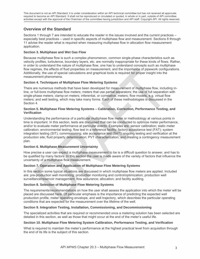
Sections 1 through 7 are intended to educate the reader in the issues involved and the current practices – especially best practices – used in specific aspects of multiphase flow and measurement. Sections 8 through 11 advise the reader what is required when measuring multiphase flow in allocation flow measurement application.
Section 3. Multiphase and Wet Gas Flow
Because multiphase flow is such a complex phenomenon, common single-phase characteristics such as velocity profiles, turbulence, boundary layers, etc. are normally inappropriate for these kinds of flows. Rather, in order to understand the nature of multiphase flow, one has to understand concepts such as multiphase flow regimes, the effects of fluid properties on measurement, and the importance of pipework configurations. Additionally, the use of special calculations and graphical tools is required for proper insight into the measurement phenomena.
Section 4. Techniques of Multiphase Flow Metering Systems
There are numerous methods that have been developed for measurement of multiphase flow, including in-line, or full-bore multiphase flow meters; meters that use partial separators; the use of full separation with single-phase meters; clamp-on meters; inferential, or correlative, meters; flow models, e.g. virtual flow meters; and well testing, which may take many forms. Each of these methodologies is discussed in the Section 4.
Section 5. Multiphase Flow Metering Systems – Calibration, Correction, Performance Testing, and Verification
Understanding the performance of a particular multiphase flow meter or methodology at various points in time is important. In this section, tests are discussed that can be conducted to optimize meter performance, and/or to evaluate meter performance at particular events. Examples are: sensor calibration; static meter calibration; environmental testing; flow test in a reference facility; factory acceptance test (FAT); system integration testing (SIT); commissioning; site acceptance test (SAT); ongoing testing and verification at the production site; fluid property determination; PVT characterization; and creating a contingency measurement plan.
Section 6. Multiphase Measurement Uncertainty
How precise a user can expect a multiphase measurement to be is a difficult question to answer, and has to be qualified by many factors. In this section the user is made aware of the variety of factors that influence the uncertainty of a multiphase flow measurement.
Section 7. Operation and Application of Multiphase Flow Metering Systems
In this section some typical situations are discussed in which multiphase flow meters are applied. Included are: pre-production well monitoring; production monitoring and control/optimization; production well surveillance/reservoir management; flow assurance; allocation; and facility auditing.
Section 8. Selection of Multiphase Flow Metering Systems
The requirements/recommendations on how the user shall assess the application into which the meter will be placed are discussed here. Of particular emphasis is the importance of predicting the expected well production profile, meter operating envelope, and well trajectory, which describes the particular operating conditions that are expected for the measurement over the lifetime of the well.
Section 9. Integration Testing, Installation, Commissioning, and Decommissioning
The specialized activities that are required or recommended once a metering solution has been selected are detailed in this section, as well as those that might occur at the end of the meter’s useful life.
Section 10. Multiphase Flow Metering System Calibration, Performance Testing, and Verification
What is required to maintain the meter’s performance at the highest practical level from acquisition through the end of its life is the subject of this section.

This document is not an API Standard; it is under consideration within an API technical committee but has not received all approvals required to become an API Standard. It shall not be reproduced or circulated or quoted, in whole or in part, outside of API committee activities except with the approval of the Chairman of the committee having jurisdiction and API staff. Copyright API. All rights reserved.
API MPMS Chapter 20.3 – Multiphase Flow Measurement 4
Section 11. Operation
A number of activities are required of the user during routine operation of the meter. Included among these are requirements regarding safety, support, maintenance, data handling, and audits.
Annex A. Example Template for MPFM Selection
This sheet is intended to assist the user in understanding the production profile of the application, both in terms of its flow rates and composition, over the expected life of the well, and how well it matches the OE of the meter.
Annex B. Typical MPFM Reports
Reports written at important points in the life of any meter put into service should become a part of its permanent record, including examples of an inspection and calibration report, and a commissioning report.
Annex C. Example Test Matrix for a Multiphase Flow Metering System
Bibliography

This document is not an API Standard; it is under consideration within an API technical committee but has not received all approvals required to become an API Standard. It shall not be reproduced or circulated or quoted, in whole or in part, outside of API committee activities except with the approval of the Chairman of the committee having jurisdiction and API staff. Copyright API. All rights reserved.
API MPMS Chapter 20.3 – Multiphase Flow Measurement 5
1 Scope
This standard addresses multiphase flow measurement in the production environment, upstream of the custody transfer (single-phase) measurement point, where allocation measurement for onshore, offshore, or subsea is applied. Other multiphase flow measurement applications such as reservoir management, well tests, and flow assurance, can also use the standard as a reference or guide. However, the focus of this standard is on those applications where the accuracy of multiphase flow measurement for allocation systems is required.
This document refers to existing standards and recommended practices to supplement the guidance it provides in this subject area. The document addresses principles used in multiphase flow measurement, multiphase metering types and classifications, assessment of expected performance, and selecting and operating multiphase measurement systems. Operational requirements or constraints are addressed, including expectations for flow meter acceptance, calibration criteria, flow loop and in-situ verifications, and other guidance specific to different multiphase flow metering applications. The document does not address specific meter configurations.
2 Terms, Definitions, Abbreviations and Symbols
For the purposes of this document, the following terms and definitions apply. The definitions for many terms used in this document can found in ISO/IEC Guide 98-3:2008 [14] unless specified otherwise.
2.1 Terms and Definitions 2.1.1
actual conditions
The actual or operating conditions (pressure and temperature) at which fluid properties or volume flow rates are expressed.
2.1.2
allocation
The (mathematical) process of assigning portions of a commingled production stream to the sources, typically zones in a well, wells, leases, units, or production facilities, which contributed to the total flow through a custody transfer or allocation measurement point.
2.1.3
allocation measurement
Measurement of production from individual entities (zones, wells, fields, leases or producing units) in order to determine the percentage of hydrocarbon and associated fluids or energy contents to attribute to each entity, when compared to the total production from the entire system (reservoir, production system, gathering system). It is required when the entities have two or more different working interest owners, or when they have different royalty obligations.
2.1.4
allocation meter
A device used to measure the flow rates from a single well or input flowline for the purpose of allocation (2.1.2); not to be confused with the reference meter (2.1.36).
2.1.5
calibration
The three step process of:
1. verifying the accuracy of an instrument at various points over its operating range, possibly in both the ascending and descending direction. See the definition of verification (2.1.48).
2. adjusting the instrument, if it exceeds a specified tolerance, to conform to a measurement or reference standard.
3. re-verification, if adjustments were made, thus providing accurate values over the instrument’s prescribed operating range.
This document is not an API Standard; it is under consideration within an API technical committee but has not received all approvals required to become an API Standard. It shall not be reproduced or circulated or quoted, in whole or in part, outside of API committee activities except with the approval of the Chairman of the committee having jurisdiction and API staff. Copyright API. All rights reserved.
API MPMS Chapter 20.3 – Multiphase Flow Measurement 6
2.1.6
commingle
To combine the hydrocarbon streams from two or more wells, units, leases, production zones, or production facilities into common vessels or pipelines.
2.1.7
compact separation
The separation of fluids in a production stream using equipment that is much smaller than that normally employed as a gravity-based separator, and which can result in either full (complete) separation (2.1.14) or partial separation (2.1.31).
2.1.8
custody transfer
Measurement of high accuracy where custody of a product is transferred from one party to another, normally accompanied by a financial transaction based on this measurement.
2.1.9
emulsion
Colloidal mixture of two immiscible fluids, one being dispersed in the other in the form of fine droplets.
2.1.10
equations of state
EOS
Equations which relate the compositions, pressures, temperatures, and various other physical properties of gases and liquids to one another, and are used to predict the transformation of physical state when conditions change (see PVT relationship (2.1.35)).
2.1.11
fiscal measurement
Measurement activities that have direct impact on revenue allocation, i.e. the allocation of production, either among partners or for the purpose of royalty payments.
2.1.12
flow regime
The physical geometry exhibited by a multiphase flow in a conduit; the geometrical distribution in space and time of the individual phase components, i.e. oil, gas, water, any injected chemicals, etc. For example, liquid occupying the bottom of a horizontal conduit with the gas phase flowing above.
2.1.13
fluid
A substance readily assuming the shape of the container in which it is placed; e.g. oil, gas, water or mixtures of these.
2.1.14
full separation
complete separation
The separation of fluids in a three-phase production stream in which the resulting streams are not multiphase, i.e. there are no liquids in the gas stream, gas in the liquid stream, or commingled oil and water. See compact separation (2.1.7) and partial separation (2.1.31).
This document is not an API Standard; it is under consideration within an API technical committee but has not received all approvals required to become an API Standard. It shall not be reproduced or circulated or quoted, in whole or in part, outside of API committee activities except with the approval of the Chairman of the committee having jurisdiction and API staff. Copyright API. All rights reserved.
API MPMS Chapter 20.3 – Multiphase Flow Measurement 7
2.1.15
gas-liquid ratio
GLR
The ratio of gas volume flow rate to the total liquid volume flow rate at any point, expressed at standard conditions, usually in standard cubic feet per barrel (scf/bbl) or standard cubic meters of gas per cubic meter of total liquid (m3/m3).
2.1.16
gas-oil ratio
GOR
The ratio of gas volume flow rate to the liquid hydrocarbon volume flow rate at any point, expressed at standard conditions, usually in standard cubic feet per barrel (scf/bbl) or standard cubic meters of gas per cubic meter of liquid hydrocarbon (m3/m3).
2.1.17
gas volume expansion factor
The ratio of the volume of one mole of gas at standard conditions to the volume of one mole of the same gas at in-situ (actual) pressure and temperature conditions. Volume expansion factor thus describes the expected change in volume in bringing the gas from actual conditions to standard surface conditions.
2.1.18
gas volume fraction
GVF
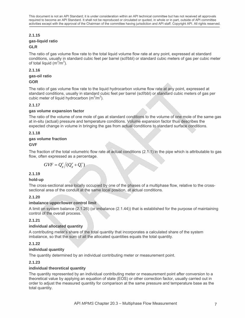
The fraction of the total volumetric flow rate at actual conditions (2.1.1) in the pipe which is attributable to gas flow, often expressed as a percentage.
)( vl
vg
vg QQQGVF
2.1.19
hold-up
The cross-sectional area locally occupied by one of the phases of a multiphase flow, relative to the cross-sectional area of the conduit at the same local position, at actual conditions.
2.1.20
imbalance upper/lower control limit
A limit on system balance (2.1.26) (or imbalance (2.1.44)) that is established for the purpose of maintaining control of the overall process.
2.1.21
individual allocated quantity
A contributing meter’s share of the total quantity that incorporates a calculated share of the system imbalance, so that the sum of all the allocated quantities equals the total quantity.
2.1.22
individual quantity
The quantity determined by an individual contributing meter or measurement point.
2.1.23
individual theoretical quantity
The quantity represented by an individual contributing meter or measurement point after conversion to a theoretical value by applying an equation of state (EOS) or other correction factor, usually carried out in order to adjust the measured quantity for comparison at the same pressure and temperature base as the total quantity.

This document is not an API Standard; it is under consideration within an API technical committee but has not received all approvals required to become an API Standard. It shall not be reproduced or circulated or quoted, in whole or in part, outside of API committee activities except with the approval of the Chairman of the committee having jurisdiction and API staff. Copyright API. All rights reserved.
API MPMS Chapter 20.3 – Multiphase Flow Measurement 8
2.1.24
liquid volume fraction
LVF
The fraction of the total volumetric flow rate at actual conditions (2.1.1) in the pipe which is attributable to liquid flow, often expressed as a percentage:
)( vg
vl
vl QQQLVF
2.1.25
Lockhart-Martinelli parameter
A dimensionless parameter (usually shown in equations as X) used to indicate the degree of “wetness” of a wet gas at actual conditions, defined as:
l
g
g
l
Q
QX
2.1.26
material balance
system balance
The difference between the measured total quantity and the sum of the individual theoretical quantities (2.1.23). Also called the system balance.
2.1.27
multiphase flow
Flow of a composite fluid which includes natural gas, hydrocarbon liquids, water, and injected fluids, or any combination of these.
2.1.28
oil-continuous multiphase flow
Multiphase flow in which the water and any other liquids present are distributed as droplets surrounded by liquid hydrocarbons (oil) in the liquid phase.
2.1.29
oil shrinkage factor
The ratio of an oil volume at stock tank or other intermediate conditions to the volume of that same oil at actual metering conditions.
2.1.30
operating envelope
OE
A description of the expected performance of a multiphase flow meter in liquid and gas flow rates, gas volume fraction (2.1.18), and water-liquid ratio (2.1.51).
NOTE It is often plotted on the flow and composition maps as measurement uncertainty contours.
2.1.31
partial separation
The separation of production fluids resulting in streams likely to be multiphase, i.e. wet gas and gassy liquid streams. See compact separation (2.1.7) and full separation (2.1.14).
2.1.32
phase
A term used in the sense of one constituent in a mixture of several. In particular, the term refers to oil, gas, water, or any other constituent in a mixture of any number of these.

This document is not an API Standard; it is under consideration within an API technical committee but has not received all approvals required to become an API Standard. It shall not be reproduced or circulated or quoted, in whole or in part, outside of API committee activities except with the approval of the Chairman of the committee having jurisdiction and API staff. Copyright API. All rights reserved.
API MPMS Chapter 20.3 – Multiphase Flow Measurement 9
2.1.33
phase mass fraction
The mass flow rate of one of the phases of a multiphase flow, relative to the total multiphase mass flow rate.
2.1.34
phase volume fraction
The volume flow rate of one of the phases of a multiphase flow at actual conditions, relative to the total multiphase volume flow rate, e.g. gas volume fraction (2.1.18).
2.1.35
pressure-volume-temperature (PVT) relationship
Application of equations of state (EOS) (2.1.10) to a composite fluid to calculate the change in properties in going from one set of conditions (P and T) to another.
2.1.36
reference meter
A flow meter used for the specific purpose of measuring the flow rate of one phase of the commingled stream, e.g. the liquid hydrocarbon flow rate. Sometimes reference meters are used to measure more than one phase, e.g. when total liquid flow and watercut are measured to determine oil and water rates.
2.1.37
slip
Conditions that exists when the phases have different velocities at a cross-section of a conduit.
2.1.38
slip ratio
A means of quantitatively expressing slip as the phase velocity ratio between the phases.
2.1.39
slip velocity
The phase velocity difference between two phases.
2.1.40
solution gas factor
gas solubility factor
The amount of gas released from solution of a given volume of oil in going from actual metering conditions to standard conditions.
NOTE Also called gas solubility factor, this can be expressed, for example, in standard cubic feet per barrel (scf/bbl) or cubic meter per cubic meter (m3/m3).
2.1.41
standard conditions
A set of standard (or reference) conditions, in terms of pressure and temperature, at which fluid properties or volume flow rates are expressed.
2.1.42
standard deviation
The square root of the variance of a random variable.
2.1.43
superficial phase velocity
The flow velocity of one phase of a multiphase flow, assuming that the phase occupies the whole conduit by itself. It may also be defined by the relationship (phase volume flow rate/pipe cross-sectional area).

This document is not an API Standard; it is under consideration within an API technical committee but has not received all approvals required to become an API Standard. It shall not be reproduced or circulated or quoted, in whole or in part, outside of API committee activities except with the approval of the Chairman of the committee having jurisdiction and API staff. Copyright API. All rights reserved.
API MPMS Chapter 20.3 – Multiphase Flow Measurement 10
2.1.44
system imbalance
material balance
The difference between the measured total quantity and the sum of the individual theoretical quantities (2.1.23), sometimes referred to as the material balance.
2.1.45
true value
The underlying characteristic of the measurand which would be recorded if the measurement were perfect, i.e. there were no random or systematic measurement errors.
2.1.46
uncertainty of allocation meter
The uncertainty of an individual theoretical quantity (2.1.23) relative to the flowing conditions experienced by the meter, which includes the uncertainty from all sources, including the meter, any uncertainty in EOS application, and uncertainties due to errors of ancillary devices such as pressure and temperature.
2.1.47
variance
The expected value of the square of the difference between the measurement and its mean value.
2.1.48
verification
The process of confirming the accuracy of a meter or instrument.
2.1.49
void fraction
gas hold-up
The cross-sectional area locally occupied by the gas phase of a multiphase flow, relative to the cross-sectional area of the conduit at the same local position. Also known as gas hold-up.
2.1.50
watercut
WC
The water volume flow rate, relative to the total liquid volume flow rate (oil and water), both converted to volumes at standard pressure and temperature.
NOTE The WC is normally expressed as a percentage.
2.1.51
water-liquid ratio
WLR
The water volume flow rate, relative to the total liquid volume flow rate (oil and water), at the actual conditions (operating pressure and temperature), expressed as a percentage.
2.1.52
well trajectory
The trajectory of production parameters displayed by a well over time, sometimes shown in a flow or composition map [e.g. see Sections 3.3 and 3.6].

This document is not an API Standard; it is under consideration within an API technical committee but has not received all approvals required to become an API Standard. It shall not be reproduced or circulated or quoted, in whole or in part, outside of API committee activities except with the approval of the Chairman of the committee having jurisdiction and API staff. Copyright API. All rights reserved.
API MPMS Chapter 20.3 – Multiphase Flow Measurement 11
2.1.53
well production profile
Expected production performance in flow and composition of a well, often plotted as uncertainty contours on the flow and composition maps. It is the region around the well trajectory (2.1.52) that accounts for the uncertainty of production estimates.
2.1.54
wet gas
A subset of multiphase flow in which the dominant fluid is gas and in which there is a presence of some liquid.
2.2 Abbreviations and Symbols
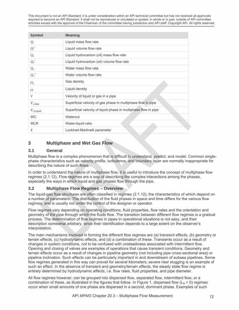
Symbol Meaning
A Pipe cross-sectional area
APipe Pipe fractional cross-sectional area occupied by ith phase, gas or liquid
AGas Cross-sectional area of pipe occupied by gas flow
ALiquid Cross-sectional area of pipe occupied by liquid flow
API American Petroleum Institute
i Liquid or gas volume fraction
BOPD Barrels of oil per day
EOS Equation(s) of state
FAT Factory acceptance test
GOR Gas-oil ratio
GLR Gas-liquid ratio
GUM ISO Guide to uncertainty in measurement [14]
GVF Gas volume fraction
I System imbalance
ISO International Organization for Standardization
Gas Gas holdup
Liquid Liquid holdup
LVF Liquid volume fraction
MCS Monte Carlo simulation
MPFM Multiphase flow meter
NFOGM Norwegian Society for Oil and Gas Measurement
OE Operating envelope
P, T Pressure and temperature at measurement (actual) conditions
psi Pounds per square inch
PVT Pressure-volume-temperature
q Mean value of a random variable q
Qg Gas mass flow rate
Qgv Gas volume flow rate
This document is not an API Standard; it is under consideration within an API technical committee but has not received all approvals required to become an API Standard. It shall not be reproduced or circulated or quoted, in whole or in part, outside of API committee activities except with the approval of the Chairman of the committee having jurisdiction and API staff. Copyright API. All rights reserved.
API MPMS Chapter 20.3 – Multiphase Flow Measurement 12
Symbol Meaning
Ql Liquid mass flow rate
Qlv Liquid volume flow rate
Qo Liquid hydrocarbon (oil) mass flow rate
Qov Liquid hydrocarbon (oil) volume flow rate
Qw Water mass flow rate
Qwv Water volume flow rate
g Gas density
l Liquid density
V Velocity of liquid or gas in a pipe
Vs,Gas Superficial velocity of gas phase in multiphase flow in pipe
Vs,Liquid Superficial velocity of liquid phase in multiphase flow in pipe
WC Watercut
WLR Water-liquid ratio
X Lockhart-Martinelli parameter
3 Multiphase and Wet Gas Flow
3.1 General Multiphase flow is a complex phenomenon that is difficult to understand, predict, and model. Common single-phase characteristics such as velocity profile, turbulence, and boundary layer are normally inappropriate for describing the nature of such flows.
In order to understand the nature of multiphase flow, it is useful to introduce the concept of multiphase flow regimes (2.1.12). Flow regimes are a way of describing the complex interactions among the phases, especially the ways in which liquid and gas phases flow through the pipe.
3.2 Multiphase Flow Regimes – Overview The liquid-gas flow structures are often classified in regimes (2.1.12), the characteristics of which depend on a number of parameters. The distribution of the fluid phases in space and time differs for the various flow regimes, and is usually not under the control of the designer or operator.
Flow regimes vary depending on operating conditions, fluid properties, flow rates and the orientation and geometry of the pipe through which the fluids flow. The transition between different flow regimes is a gradual process. The determination of flow regimes in pipes in operational situations is not easy, and their description somewhat arbitrary, since their identification depends to a large extent on the observer’s interpretation.
The main mechanisms involved in forming the different flow regimes are (a) transient effects, (b) geometry or terrain effects, (c) hydrodynamic effects, and (d) a combination of these. Transients occur as a result of changes in system conditions, not to be confused with unsteadiness associated with intermittent flow. Opening and closing of valves are examples of operations that cause transient conditions. Geometry and terrain effects occur as a result of changes in pipeline geometry (not including pipe cross-sectional area) or pipeline inclination. Such effects can be particularly important in and downstream of subsea pipelines. Some flow regimes generated in this way can prevail for several kilometers; severe riser slugging is an example of such an effect. In the absence of transient and geometry/terrain effects, the steady state flow regime is entirely determined by hydrodynamic effects, i.e. flow rates, fluid properties, and pipe diameter.
All flow regimes however, can be grouped into dispersed flow, separated flow, intermittent flow, or a combination of these, as illustrated in the figures that follow. In Figure 1, dispersed flow (LB = 0) regimes occur when small amounts of one phase are dispersed in a second, dominant phase. Examples of such

This document is not an API Standard; it is under consideration within an API technical committee but has not received all approvals required to become an API Standard. It shall not be reproduced or circulated or quoted, in whole or in part, outside of API committee activities except with the approval of the Chairman of the committee having jurisdiction and API staff. Copyright API. All rights reserved.
API MPMS Chapter 20.3 – Multiphase Flow Measurement 13
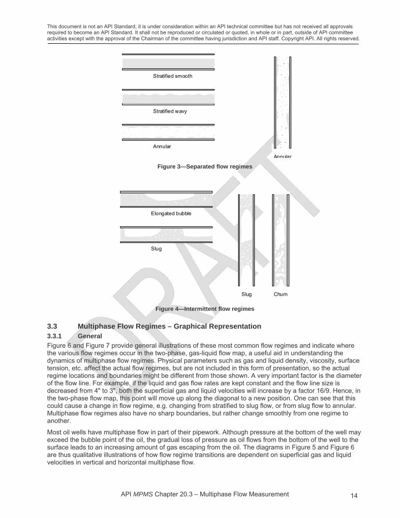
flows are bubble flow and mist flow (Figure 2). Separated flow (LS = 0) is characterized by a non-continuous phase distribution in the radial direction and a continuous phase distribution in the axial direction. Examples of such flows are stratified and annular (with low droplet entrained fraction), as shown in Figure 3. Intermittent flow is characterized by being non-continuous in the axial direction, and therefore exhibits locally unsteady behavior. Examples of such flows are elongated bubble, churn and slug flow (Figure 4). The flow regimes shown in Figures 2 to 4 are all hydrodynamic two-phase gas-liquid flow regimes.
Flow such as that shown in Figure 1 illustrates a key point that will be emphasized in Section 4 on metering techniques. The point is that flow regimes such as this one are actually two flow regimes in series. Any meter that is designed to work at the average gas volume fraction (GVF), water-liquid ratio (WLR) and flow rates measured over a long period in this application will fail, therefore, it needs to work well in both the gas-dominant and liquid-dominant domains as shown. This is a key characteristic of successful multiphase flow metering systems.
Flow regimes effects caused by liquid-liquid interactions are normally significantly less pronounced than those caused by liquid-gas interactions. In this context, the liquid-liquid portion of the flow can therefore often be considered as a dispersed flow. However, some properties of the liquid-liquid mixture depend on the volumetric ratio of the two liquid components.
Figure 1—Multiphase flow regime concepts
Figure 2—Dispersed flow regimes
Separated flow Dispersed flow
Intermittentflow
L LB S
Bubble
Mist
Bubble Mist
This document is not an API Standard; it is under consideration within an API technical committee but has not received all approvals required to become an API Standard. It shall not be reproduced or circulated or quoted, in whole or in part, outside of API committee activities except with the approval of the Chairman of the committee having jurisdiction and API staff. Copyright API. All rights reserved.
API MPMS Chapter 20.3 – Multiphase Flow Measurement 14
Figure 3—Separated flow regimes
Figure 4—Intermittent flow regimes
3.3 Multiphase Flow Regimes – Graphical Representation 3.3.1 General
Figure 6 and Figure 7 provide general illustrations of these most common flow regimes and indicate where the various flow regimes occur in the two-phase, gas-liquid flow map, a useful aid in understanding the dynamics of multiphase flow regimes. Physical parameters such as gas and liquid density, viscosity, surface tension, etc. affect the actual flow regimes, but are not included in this form of presentation, so the actual regime locations and boundaries might be different from those shown. A very important factor is the diameter of the flow line. For example, if the liquid and gas flow rates are kept constant and the flow line size is decreased from 4" to 3", both the superficial gas and liquid velocities will increase by a factor 16/9. Hence, in the two-phase flow map, this point will move up along the diagonal to a new position. One can see that this could cause a change in flow regime, e.g. changing from stratified to slug flow, or from slug flow to annular. Multiphase flow regimes also have no sharp boundaries, but rather change smoothly from one regime to another.
Most oil wells have multiphase flow in part of their pipework. Although pressure at the bottom of the well may exceed the bubble point of the oil, the gradual loss of pressure as oil flows from the bottom of the well to the surface leads to an increasing amount of gas escaping from the oil. The diagrams in Figure 5 and Figure 6 are thus qualitative illustrations of how flow regime transitions are dependent on superficial gas and liquid velocities in vertical and horizontal multiphase flow.
Stratified smooth
Annular
Stratified wavy
Annular
Elongated bubble
Churn
Slug
Slug

This document is not an API Standard; it is under consideration within an API technical committee but has not received all approvals required to become an API Standard. It shall not be reproduced or circulated or quoted, in whole or in part, outside of API committee activities except with the approval of the Chairman of the committee having jurisdiction and API staff. Copyright API. All rights reserved.
API MPMS Chapter 20.3 – Multiphase Flow Measurement 15
The use of the term superficial velocity (2.1.43) is often used in flow regime maps, and requires explanation. The superficial gas velocity Vs,Gas is the gas velocity as if the gas were flowing in the pipe without liquids, in other words the volumetric total gas throughput Qv
Gas, at operating temperature and pressure, divided by the total cross sectional area of the pipe APipe. For the superficial liquid velocity, the same can be derived, with results shown in Equations 1–4. AGas and ALiquid are the fractional areas occupied by the gas and liquid in the pipe as if they were separated, and VGas and VLiquid are the actual gas and liquid velocities at line pressure and temperature.
Pipe
LiquidLiquid A
A Liquid Hold-up (1)
Pipe
GasGas A
A Gas hold-up/Void fraction (2)
GasGas
Pipe
Gas
Gas
Gas
Pipe
GasGas, . V
A
A
A
Q
A
QV
vv
s (3)
LiquidLiquidPipe
Liquid
Liquid
Liquid
Pipe
LiquidLiquid, . V
A
A
A
Q
A
QV
vv
s (4)
One other topic needs attention. When gas and liquid flow together in a pipe, the fraction of the pipe’s cross-sectional area covered by liquid will be greater than it is under non-flowing conditions, due to the effect of slip (2.1.37) between liquid and gas. The lighter gas phase will normally move much faster than the heavier liquid phase, and in addition, the liquid has the tendency to accumulate in horizontal and inclined pipe segments. The liquid and gas fractions of the pipe cross-sectional area, as measured under two-phase flow conditions, are known as liquid hold-up and gas void fraction, respectively, and are defined in Equations 1 and 2. Owing to slip, the liquid hold-up will be larger than the liquid volume fraction. Liquid hold-up is equal to the liquid volume fraction only under conditions of no slip, when the two phases travel at equal velocities. The concepts are illustrated in Figure 5.
Figure 5—Gas void fraction, gas volume fraction, and slip

This document is not an API Standard; it is under consideration within an API technical committee but has not received all approvals required to become an API Standard. It shall not be reproduced or circulated or quoted, in whole or in part, outside of API committee activities except with the approval of the Chairman of the committee having jurisdiction and API staff. Copyright API. All rights reserved.
API MPMS Chapter 20.3 – Multiphase Flow Measurement 16
Note that with the liquid hold-up and the actual velocities, the superficial gas and liquid velocities can be calculated. Also note that Gas,Gas sVV , always.
In addition to the two-phase liquid-gas flow maps used in Figure 6 and Figure 7 to illustrate vertical and horizontal flow regimes, there is another graphical tool that is useful. The composition map is helpful in understanding the constituents of the multiphase mixture, and will be discussed in later in this section and in Section 6 on uncertainty.
3.3.2 Vertical Flow Regimes
Typical positions of the various vertical flow regimes are shown in the two-phase flow map of Figure 6. Note that above a particular superficial gas velocity, the multiphase flow is annular for all superficial liquid velocities.
It is worth noting that all vertical flow regimes tend toward axially symmetry, i.e. liquid and gas phases have no natural tendency to preferentially separate in a particular azimuthal direction, unlike horizontal regimes on which gravity pulls the heavier liquids toward the bottom of the pipe. For this reason, vertical installation is preferred for most (but not all) MPFMs in order to simplify the range of flow regimes present.
Figure 6—A generic two-phase vertical flow map, log-log scale
3.3.3 Horizontal Flow Regimes
In horizontal flow, as was the case with vertical flow, the boundaries between regimes are functions of such factors as pipe diameter, interfacial tension, and density of the phases. The following map shown in Figure 7 is a qualitative illustration of how flow regime transitions depend on superficial gas and liquid velocities in horizontal multiphase flow. A map such this is only valid for a specific pipe, pressure, and multiphase fluid.
Note that, in contrast to vertical flow regimes, all horizontal flow regimes tend not to be axially symmetric, i.e. the effects of gravity cause the heavier liquids to prefer the bottom of the pipe while the lighter gas phase travels along the top.
0.01 0.1 1.0 10 100
0.1
1.0
10
100
0.01
Superficial gas velocity (m/s)
Su
per
fic i
a l li
qu
i d v
e loc
ity
(m/s
)
Finely dispersed bubble
Slug
Bubble Churn
Annular

This document is not an API Standard; it is under consideration within an API technical committee but has not received all approvals required to become an API Standard. It shall not be reproduced or circulated or quoted, in whole or in part, outside of API committee activities except with the approval of the Chairman of the committee having jurisdiction and API staff. Copyright API. All rights reserved.
API MPMS Chapter 20.3 – Multiphase Flow Measurement 17
Figure 7—A generic two-phase horizontal flow map, log-log scale
3.4 Composition and Fluid Properties 3.4.1 Overview
As important as characterizing the flow rates of liquid and gas through closed pipes is to understanding multiphase flow, equally as important is identification of its constituents and their physical properties. At the most basic level, this means discerning what is the fractional portion of each phase present at a point in the pipe, i.e. phase fractions. Coupled with the knowledge of phase velocities discussed in Section 3.3, this identifies the flow in terms of its actual (at line pressure) phase rates.
Attention to the nature and properties of the fluids that pass through a meter in service is essential to ensure proper meter performance. Sampling of the fluids is the most straightforward means of understanding these properties for a given well at a given point in time.
Identification of the kinds of fluid sampling necessary to maintain the specified accuracy of the meter, the estimated frequency of sampling, as well as the kinds of information that should be derived from the sample, will normally be required. This ordinarily is based on the selected meter’s sensitivity to fluid property changes, such information having been supplied by the meter vendor. Frequency of sampling shall be determined from both meter sensitivity coefficients, and from estimates of the speed at which fluid properties are changing once production has begun.
However, there is a great deal more that is needed to fully identify the flow from the perspective of composition. The most important of these will be discussed herein.
3.4.2 Liquid Hydrocarbon (Oil) Properties
3.4.2.1 General
The liquid hydrocarbons most commonly encountered fall into three general categories as detailed in the following pieces and the properties of which are shown in Table 1.
0.01 0.1 1.0 10 100
0.1
1.0
10
100
0.01
Superficial gas velocity (m/s)
Su
per
f ic i
a l li
qu
id v
e lo
c it y
( m/
s ) Bubble
Slug
Stratified
Wave
Annular
Mist
Plug Mist

This document is not an API Standard; it is under consideration within an API technical committee but has not received all approvals required to become an API Standard. It shall not be reproduced or circulated or quoted, in whole or in part, outside of API committee activities except with the approval of the Chairman of the committee having jurisdiction and API staff. Copyright API. All rights reserved.
API MPMS Chapter 20.3 – Multiphase Flow Measurement 18
Table 1—Fluid properties of typical produced liquids at standard conditions
Relative Density Range API Gravity Range (degrees)
Viscosity Range (centipoise at 20 °C)
Gas Condensates <0.78 >50° <5
Black (Light) Oil >0.78
<0.934 20°–50° >5
<1000
Heavy Oil >0.934 <20° >1000
Water 1.0–1.33 (dependent on
salinity) Not applicable 1.0
3.4.2.2 Gas Condensate
Gas condensate, or just condensate, is a mixture of low-density hydrocarbon liquids that condenses out of a natural gas stream when the temperature is reduced below the hydrocarbon dew point of the mixture.
Condensates sometimes present measurement problems, particularly if they are the primary liquid component of wet gas. Often such gas-dominant systems are a greater measurement challenge than liquid-dominant systems, especially with respect to estimating the liquid rates and composition.
For more on the properties of gas condensates, the reader is referred to GPA Standard 2145 [13] on the subject.
3.4.2.3 Black Oil, Light Crude Oil
This hydrocarbon liquid designation applies to those crude oils with properties that range between those of gas condensate and heavy oil.
When these kinds of hydrocarbon liquids constitute most of the multiphase flow stream, measurement of both composition and rate is generally easier than it is in either gas condensate or heavy oil systems.
3.4.2.4 Heavy Oil
Hydrocarbon liquids that are referred to as heavy oil are generally those of high density – typically with an API gravity below 20°, or a relative density greater than 0.933. Heavy oil typically has high viscosity as well, making its production and transportation more difficult than that of lighter crude oils.
Measurement in heavy oil systems can be difficult for two primary reasons. First, due to the low Reynolds numbers typical of these heavy, viscous liquids, they often flow in the laminar region where discharge coefficients for differential meters are usually highly variable. And second, they can be prone to forming emulsions with water that be produced, the product of which can again be a liquid of high and variable viscosity, low Reynolds number, and variable discharge coefficient. The interested reader is referred to papers which discuss the effects [18][19].
3.4.3 Natural Gas Properties
Hydrocarbon gases are members of the family of compounds that normally exist in a gaseous state when produced from a reservoir through a well and into a pipeline. Consisting of chains of hydrogen and carbon atoms in various patterns, the most common ones are the C1 through C6 molecules, including methane, ethane, propane, butane, pentane, and hexane.
In addition to hydrocarbon gas molecules, there may also be present certain non-hydrocarbon gases. Hydrogen sulfide (H2S), carbon dioxide (CO2), and inert gases such as nitrogen (N2) are among the most common.
Natural gas mixtures can contain both hydrocarbon and non-hydrocarbon molecules. It is sometimes difficult to specify the properties of natural gas since these are dependent on the composition of the gas as well as on the pressure and temperature. The composition of the gas mixture can affect the flow rate measurement through, for example, the density term.

This document is not an API Standard; it is under consideration within an API technical committee but has not received all approvals required to become an API Standard. It shall not be reproduced or circulated or quoted, in whole or in part, outside of API committee activities except with the approval of the Chairman of the committee having jurisdiction and API staff. Copyright API. All rights reserved.
API MPMS Chapter 20.3 – Multiphase Flow Measurement 19
For more information on the physical properties of natural gas components and mixtures, the interested reader is referred to GPA Standard 2145 [13] and AGA Report No. 8 [11].
3.4.4 Water Properties
Water can be produced through the meter from a number of sources, for example:
water present as a liquid in the reservoir;
water produced as a vapor with natural gas;
water injected to enhance production, either as a liquid or steam.
A problem for measurement can occur when waters from two or more sources are combined, with the resulting properties mixed and possibly variable.
Water salinity is perhaps the most important property of water due to the impact it has both on the density of the water and its electrical conductivity. This is a result of the presence of salt ions held in solution. Sodium chloride (NaCl), calcium chloride (CaCl2) and potassium chloride (KCl) are the most common salts encountered in produced water, though others can sometimes be present. Electrical properties of the fluids are commonly used to determine water-liquid ratio; however this is not the case for all meters.
Water cut measurement can be dependent on the salinity value used. Unknown changes in salinity can result in unpredictable errors in the water-liquid ratio measurement. Most multiphase and wet gas meters require fluid samples on which to calibrate their response or to set the meter with associated salt properties. The response of most meters is dependent on the density or conductivity of water. Any change in these parameters will cause an error in the estimated water fraction, or water-liquid ratio, by the meter. For this reason, anything that can be done to eliminate or minimize these effects is significant.
Steam has been used for many years to reduce the viscosity of in-situ heavy oil. Steam quality – the mass fraction of a steam-water mix that is in occupied by steam – is an important parameter in steam operations.
3.4.5 Other Materials Conveyed by the Meter
From time to time, materials other than produced hydrocarbons and water will be transported through the metering system, e.g. sand. In these instances, two issues should be considered: (1) the meters ability to detect their presence and perhaps measure them, and distinguish them from produced fluids; and (2) the materials can be harmful to either the short- or long-term health of the meter e.g. erosion.
In addition to the hydrocarbons and water that will normally be produced from the reservoir and through the meter, there are other liquids that are often part of the flow stream and may need to be considered. Those that are only present for a short period during the life of the field (e.g. drilling fluids) will not be discussed here, while others that may be part of the flow stream continually (e.g. various inhibitors) are included.
A variety of chemicals are commonly injected into the flow stream, ordinarily upstream of the meter, to address various conditions that may occur. Some of the more common ones are hydrate inhibitors [methanol, monoethylene glycol (MEG)], scale inhibitors, corrosion inhibitors, wax inhibitors, asphaltene inhibitors, etc.
The use of diluents to dilute a heavy oil stream, reduce the oil viscosity, and thereby increase its ability to flow freely, is common practice.
The use of water and steam floods to increase reservoir drive has been a useful method for many years. The principal effect on multiphase meters is addition of water to the well stream that will be reflected in increased WLR. Of concern to the measurement engineer is whether the water properties of the flood water – primarily salinity – alter the properties of the commingled stream. A change in water salinity is something that MPFMs should be aware of and measures taken to ensure correct WLR estimates.
In production operations, particularly for offshore operations, it is not uncommon for sand to be produced along with oil, water, and gas. How a meter responds to the presence of sand is useful knowledge.
3.4.6 Other Fluid Effects
3.4.6.1 General
As a well is brought on line, the liquids and gas produced can sometimes react to create other compounds, some of which can be especially pernicious to both production and measurement.

This document is not an API Standard; it is under consideration within an API technical committee but has not received all approvals required to become an API Standard. It shall not be reproduced or circulated or quoted, in whole or in part, outside of API committee activities except with the approval of the Chairman of the committee having jurisdiction and API staff. Copyright API. All rights reserved.
API MPMS Chapter 20.3 – Multiphase Flow Measurement 20
3.4.6.2 Scale
Scale is a deposit of minerals that can foul pipes, valves, and other devices during production. At least some small amount of water production is required for the chemical reaction to take place. The effects on production can be severe. However, injection of suitable amounts of scale inhibitor can prevent scale buildup from taking place.
Such scale buildup on the interior meter surfaces can cause severe mismeasurement if undetected and not dealt with.
3.4.6.3 Asphaltenes
Asphaltenes are molecular substances that are found in crude oil, along with resins, aromatic hydrocarbons, and alkanes (i.e. saturated hydrocarbons). They are of particular interest to the petroleum industry because of their depositional effect in production equipment such as tubulars in oil wells. In addition, asphaltenes impart high viscosity to crude oils, negatively impacting production. The variable asphaltene concentration in crude oils within individual reservoirs creates a myriad of production problems.
The buildup of asphaltenes on the interior meter surfaces can cause severe mismeasurement if undetected and not dealt with.
3.4.6.4 Wax (Paraffin)
Paraffin wax (or simply "paraffin") is mostly found as a white, odorless, tasteless, waxy solid, with a typical melting point between approximately 47 °C and 64 °C (117 °F to 147 °F), and having a density of around 0.9 g/cm3. Wax is a mixture of alkanes usually in a homologous series of chain lengths. These materials represent a significant fraction of petroleum. In some cases, wax can coat the walls of a production system to the point where flow can be choked off.
The buildup of wax on the interior meter surfaces can cause severe mismeasurement if undetected and not dealt with.
3.4.6.5 Hydrates
Hydrates are crystalline water-based solids physically resembling ice, in which small non-polar molecules (typically gases) are trapped inside "cages" of hydrogen-bonded water molecules. Severe damage to production facilities can result from their formation, which can be inhibited by the proper injection of chemicals such as methanol or monoethylene glycol (MEG).
With respect to measurement, the principal danger with hydrates in a flowing well is their tendency to plug pressure-sensing lines, as with pressure or differential pressure transmitters. It should be noted that injection of large volumes of inhibitors e.g. MEG or methanol, can affect the calibration, and can impact the measurement accuracy.
3.4.6.6 Emulsions
An emulsion is a mixture of two or more immiscible liquids. Emulsions are part of a more general class of two-phase systems of matter called colloids. Although the terms colloid and emulsion are sometimes used interchangeably, emulsion tends to imply that both the dispersed and the continuous phase are liquid. In an emulsion, one liquid (the dispersed phase) is dispersed in the other (the continuous phase).
Emulsions can affect measurement performance. One way is through changes in physical properties that sometime occur, such as the rapid increase in viscosity that sometimes accompanies emulsions of water and heavy oils.
3.4.6.7 Foam
Foam is another mixing phenomenon that affects the physical properties of fluids that are being measured. In some conditions, the gas that is produced is mixed as bubbles contained within the liquid phase, usually hydrocarbons, forming a substance with the consistency of whipped or shaving cream. Flow characteristics and measurement can be difficult under these circumstances.
3.4.7 Changing Fluid Properties over Field Life
Almost all meters are affected when fluid properties change during the field life. In this regard, two questions have to be answered. First, does the metering system include any sensors for detecting fluid property

This document is not an API Standard; it is under consideration within an API technical committee but has not received all approvals required to become an API Standard. It shall not be reproduced or circulated or quoted, in whole or in part, outside of API committee activities except with the approval of the Chairman of the committee having jurisdiction and API staff. Copyright API. All rights reserved.
API MPMS Chapter 20.3 – Multiphase Flow Measurement 21
changes, and potentially accounting for them in the meter’s response? And second, if the meter requires new fluid properties information, where will such information be derived? Fluid sampling is the most common source of fluid property data, but can be difficult to obtain in some instances, e.g. for subsea meters.
Changes in fluid properties can substantially impact meter performance depending on the type of sensors used and the technology used. Some technologies are impacted by a particular change in fluid properties and some are not. When evaluating multiphase meters, changes in fluid properties shall be considered. The following list (this list is not all inclusive) of key fluid properties are examples of fluid properties that can impact meter performance when changes occur:
water salinity (see Section 3.4.4);
H2S content in gas and liquid;
gas and liquid density;
HC composition;
phase viscosities;
phase behavior including oil continuous versus water continuous liquid phase.
When MPFMs are used for testing multiple wells in a typical test header configuration, changes in fluid properties between wells can yield substantially different quality in results. Again, dependent on the technologies employed.
3.4.8 Phase Properties/PVT Effects/Flowing Versus Standard Conditions
Flow rates are measured at actual flowing conditions while volumes are reported at standard conditions. Therefore, an equation of state (EOS) conversion is required. The methodology for performing these conversions is by applying an equation of state (EOS) to the actual volumes measured.
To be of use in normal practice, the volumetric flow rates measured by an MPFM at actual meter conditions (2.1.1) have to be converted to rates normalized to standard pressure and temperature conditions (2.1.41), normally one atmosphere of pressure and 60 °F. Because actual meter conditions tend to be at higher pressures and temperatures, the gas expands and the oil shrinks as pressure and temperature are reduced. Three coefficients are required to describe this process, namely the gas expansion factor, the oil shrinkage factor, and the solution gas factor. These conversion factors are usually tabulated over the anticipated meter conditions, covering the expected range of operating pressures and temperatures. These are ordinarily supplied by the meter user to the meter manufacturer, or to whoever is tasked with the conversion to standard conditions.
The oil and gas flow rates at standard conditions can then be calculated:
Gas (standard conditions) = Gas (meter conditions) × Gas Volume Expansion Factor + Oil (standard conditions) × Solution Gas Factor
Oil (standard conditions) = Oil (meter conditions) × Shrinkage Factor
Finally, the gas-oil ratio GOR is calculated as:
Gas-Oil Ratio (GOR) = Gas (standard conditions) / Oil (standard conditions)
where the gas at standard conditions accounts for contributions from both the measured and solution gas.
Any errors in developing these conversion factors from the fluid equation of state (EOS) would add to the measurement uncertainty of the meter itself. Commercial or proprietary PVT packages are commonly used in this process. By properly simulating the actual flashing process, from gas/liquid separation stages and metering points to stock tank conditions, should ensure the most accurate conversion factors. Using a single flash of the production fluid from meter condition to standard condition will likely introduce errors if the actual production fluid undergoes multiple separations at intermediate pressures and temperatures.
It should be pointed out that if all measurements were made in units of mass, the practice of conversion from meter to standard conditions would largely be unnecessary. However, phase change calculations would still be necessary and there would likely be some final conversion to standard volume in order to be made practical with commercial terms.
This document is not an API Standard; it is under consideration within an API technical committee but has not received all approvals required to become an API Standard. It shall not be reproduced or circulated or quoted, in whole or in part, outside of API committee activities except with the approval of the Chairman of the committee having jurisdiction and API staff. Copyright API. All rights reserved.
API MPMS Chapter 20.3 – Multiphase Flow Measurement 22
3.5 Piping Aspects of Multiphase Flow 3.5.1 General
Effects due to pipework in the vicinity of the meter can be important, either in the nature of the flow through the meter – e.g. the flow regime – or in the composition of the fluids in the pipe, or both.
3.5.2 Commingled Flow
The primary effect of commingled flow is with regard to the composition of the resulting multiphase mixture. Once the flow is commingled, it is difficult to identify the properties of the contributing streams. For example, the relative proportion of two different sources can change the physical properties of the commingled flow as measured by the meter.
3.5.3 Installation Piping Effects – Orientation, Asymmetry, Swirl
In order to reduce the effects of asymmetry on the measurement, a vertical orientation is usually preferred. This is consistent with Section 3.3 on importance of flow regimes.
The effects of upstream pipework, such as bends and pipe size changes, are generally ignored in multiphase flow measurement.
The mixing of multiphase flow prior to its measurement is a common performance requirement of many multiphase flow meters. Though many elaborate techniques have been employed in the past, a “blind tee” is a commonly used method.
3.6 Multiphase Operating Envelope (OE), Well Production Profile and Trajectory 3.6.1 Overview
The concept of an operating envelope (2.1.30) of a multiphase meter is understood best by recognizing that it is one of the two parts that describe the meter’s performance in a particular well application. First, the user needs to know the well’s production profile, a prediction of the range of flow rates and composition conditions over which the well will operate over a period of time, usually its lifetime. When the production profile is coupled with the operating envelope, the flow rates and composition conditions over which the meter can perform acceptably, the user can judge how well the meter and well are suited for one another, or determine when in the well’s lifetime the MPFM may need to be changed or supplemented with a smaller meter.
Another concept related to the well’s envelope is its trajectory (2.1.52), the best estimate of the path the production profile will follow over its lifetime.
The most effective manner of demonstrating these concepts is through the use of graphical tools, namely flow and composition maps.
NOTE While this section refers to a single well production profile, many multiphase flow meter applications measure flow from a combination of wells. The same concept applies to production profiles for a set of wells or a complete field.
It should be noted that multiphase meters are often designed for liquid-dominant or gas-dominant multiphase flow. If the production trajectory is likely to span from liquid- to gas-dominant flow during the field life, consideration should be given to the need to change or update the meter during the field life.
3.6.2 Graphical Depiction on the Flow Map
Figure 8 is a figure taken from the NFOGM Handbook [25] illustrating the concepts of production profile, operating envelope, and well trajectory on the two-phase flow map. The red lines connecting the dots show the well’s trajectory, with its attendant uncertainty shown around it as the production profile. The meter’s envelope is shown in green, both at the ±5 % and ±10 % levels. By comparing these one can assess the suitability of a meter for a particular application through the life of the well.
It should be pointed out that both the production profile and meter operating envelopes on the flow map serve only as illustrations of the graphical methodology, and do not represent what should be expected from either in an actual field situation.

This document is not an API Standard; it is under consideration within an API technical committee but has not received all approvals required to become an API Standard. It shall not be reproduced or circulated or quoted, in whole or in part, outside of API committee activities except with the approval of the Chairman of the committee having jurisdiction and API staff. Copyright API. All rights reserved.
API MPMS Chapter 20.3 – Multiphase Flow Measurement 23
Figure 8—Illustration of concepts of production profile, operating envelope, and well trajectory on the two-phase flow map
3.6.3 Graphical Depiction on the Composition Map
Figure 9 is another figure taken from the NFOGM Handbook [25] illustrating the concepts of production profile, operating envelope, and trajectory on the composition map. The composition map is a plot of where a well is producing, or a meter operating, with regard to GVF and WLR. The red lines connecting the dots show the well’s trajectory, with the uncertainty of the trajectory shown around it. The meter’s WLR envelope is shown in green at various levels; the GVF uncertainty is shown on the flow map. As with the flow map, by comparing the production profile and meter operating envelopes, one can assess how well a meter fits a particular application.
It should be pointed out that both the production profile and meter envelope on the composition map serve only as illustrations of the graphical methodology, and do not represent what should be expected from either in an actual field situation.
Because assessing the match between the production profile and the OE is such a critical task in the selection of multiphase meters, most operators have tools to assist in performing this task, such as the spreadsheet tool shown in Annex A.

This document is not an API Standard; it is under consideration within an API technical committee but has not received all approvals required to become an API Standard. It shall not be reproduced or circulated or quoted, in whole or in part, outside of API committee activities except with the approval of the Chairman of the committee having jurisdiction and API staff. Copyright API. All rights reserved.
API MPMS Chapter 20.3 – Multiphase Flow Measurement 24
Figure 9—Illustration of concepts of production profile, operating envelope, and well trajectory on the composition map
4 Techniques of Multiphase Flow Metering Systems
4.1 In-line Meters 4.1.1 Overview
In-line or full-bore multiphase flow meters are characterized by the complete measurement of phase fractions and phase flow rates being performed within the multiphase flow line, with no separation of the flow, either partial or complete.
The volume flow rate of each phase can be represented by its area fraction multiplied by the velocity of each phase. In a typical gas/water/oil application, six parameters are needed – three phase fractions and three phase velocities.
Different meters use different methods to measure or infer the six unknown parameters needed to solve the multiphase volume calculation. Some multiphase flow meters require that all phases travel at the same velocity, thus reducing the required number of measurements to the three fractions plus the common velocity. This is usually achieved through use of an ancillary device such as a mixer or a displacement (PD) meter.
Many of the commercially leading multiphase flow meters in use today are in-line devices, each being based on a subset of the flow and composition measurement principles described in the following sections.
It should be observed that for most in-line meters there is no practical reason why the device could not be used with a partial separation system if conditions warrant and the user wished to use it in this fashion.

This document is not an API Standard; it is under consideration within an API technical committee but has not received all approvals required to become an API Standard. It shall not be reproduced or circulated or quoted, in whole or in part, outside of API committee activities except with the approval of the Chairman of the committee having jurisdiction and API staff. Copyright API. All rights reserved.
API MPMS Chapter 20.3 – Multiphase Flow Measurement 25
4.1.2 Composition – WLR, GVF
4.1.2.1 Gamma Ray Absorption by the Fluid
4.1.2.1.1 General The use of low-energy gamma radiation is common in many fields, e.g. medical imaging, non-destructive testing, security systems, etc. It is also a common method of monitoring multiphase flow streams.
4.1.2.1.2 Single-Energy Gamma Ray densitometry The use of single-energy gamma ray absorption in the multiphase fluid is the most common way of measuring fluid density, one of the key parameters used in most multiphase flow meters.
4.1.2.1.3 Multiple-Energy Gamma Ray Spectroscopy By using a source that emits gamma rays with two or more different energies, one can use attenuation measurements made at these distinct spectral lines as input to a model of the multiphase fluid to obtain the relative fractions of oil, water, and gas present.
Figure 10 shows how to use this gamma-ray spectroscopy in composition measurements. Because the relative attenuation of oil, gas, and water varies dependent on the energy of the gamma-ray photon, equations relating the composition (phase fractions) of the fluid in the photon path to the measured attenuation at various energies can be written. Given enough counts to reduce the statistical uncertainty of the measured attenuation, an estimate of the three phase fractions can be made.
Several meters have been developed that use gamma-ray spectroscopy for phase fraction estimation.
Figure 10—Low-energy gamma-ray absorption by oil, gas, and water
4.1.2.1.4 Source Activity and Life Since most sources used in MPFMs are samples of radioactive isotopes, they are in a continual process of decay, which means there is less material available to launch photons as the source grows older, hence its “strength”, or activity level, is in a constant state of reduction. The normal measure of how fast this decay occurs is the so-called half-life of the source, i.e. the time period for it to decay to half its strength.
Sources vary among meters, and are chosen based on absorption characteristics of fluids at the wavelengths emitted by the source. It is important that an MPFM user is knowledgeable with regard to the sources used in any MPFM that might be selected. Not only are safety issues of prime importance, but the issue of source strength decay has to be recognized and possibly accounted for. If the half-life of the source is short compared to the period that the meter will be in place and operating, the decline in source counts during meter life has to be accommodated in the meter’s algorithms. Furthermore, it may be necessary to swap out the source at some point in time to maintain the meter’s performance.
4.1.2.2 Infrared Absorption Spectrum
By measuring the transmission spectrum of a near infrared (NIR) source of photons as the radiation passes through the fluid in the pipe, one can estimate the concentrations of the components of the flow that absorb

This document is not an API Standard; it is under consideration within an API technical committee but has not received all approvals required to become an API Standard. It shall not be reproduced or circulated or quoted, in whole or in part, outside of API committee activities except with the approval of the Chairman of the committee having jurisdiction and API staff. Copyright API. All rights reserved.
API MPMS Chapter 20.3 – Multiphase Flow Measurement 26
energy in that range. In particular, the technique is very sensitive to the presence of water, even in very low concentrations.
4.1.2.3 Permittivity of Fluid
The measurement of permittivity (relative dielectric constant) is a means of estimating the aqueous phase(s) of a multiphase stream. In particular, permittivity measurement using capacitance or microwave sensors is a common means of estimating watercut or water fraction in oil-continuous or wet gas flows [20][21][22].
4.1.2.4 Conductivity of Fluid
In some cases of multiphase flow, the amount of water is great enough that it is the dominant liquid phase. In these instances, some permittivity sensors may have difficulty dealing with a conductive medium in the space where the measurement is to be made. Some meters therefore employ inductive methods to measure conductivity of the fluid in these circumstances rather than trying to estimate permittivity, as described in Section 7.2.2.2 of the NFOGM Handbook [25].
4.1.2.5 Density from Differential Pressure
A differential meter can be used to obtain fluid density if the flow metering system has another means for estimation of flow velocity, such as cross correlation.
4.1.2.6 Coriolis Force
In flow lines where gas has been eliminated, Coriolis measurement has shown the ability to reliably estimate watercut of the two-phase liquid by use of its density measurement.
Coriolis meters have been introduced which claim the ability to operate when GVF ranges from 0 % to 25 % or 75 % to 100 %.
4.1.2.7 Pressure and Temperature
The most elemental of measurements that are always required are pressure and temperature. These are invariably needed by the meter making the measurement, but are also required in order to make the conversion from actual operating conditions to standard conditions.
4.1.3 Flow Velocity
4.1.3.1 General
In addition to measuring the composition of the fluid, i.e. the relative amounts of oil, water, and gas at the measurement point in the pipe, one has to also estimate the velocity at which each of the three phases travels through the pipe – the individual phase rates.
While conceptually the rates of each can be measured or estimated, in practice one often assumes (a) that the oil and water travel at the same velocity in the liquid phase, and (b) that the relationship between gas and liquid velocities can be described by a slip model. (See Sections 3.3 and 4.1.4.)
Some of the sensor systems used for velocity measurement are described below.
4.1.3.2 Differential Pressure Devices
The most widely used method of multiphase mass or flow velocity measurement is through use of differential meters. The most common of these is the Venturi meter, which is attractive because of the ease with which liquids may pass through. Other forms of differential-pressure inducing elements used in these applications are orifice, wedge, cone, and various forms of Venturi and Venturi nozzles.
Since meters making use of differential pressure have been extensively used and studied for many years, standards (e.g. API MPMS Chapter 14.3 [9] and ISO 5167 [16]) have been developed to guide the user in their efficient deployment to minimize problems. Although the manner in which these meters are used in a multiphase environment may be at odds with some requirements called out in these standards, the practical knowledge reflected in these documents should be used to suggest how the measurement might be optimized.
In some instances, differential pressure has been used as a means of density estimation, as mentioned in Section 4.1.2.5.

This document is not an API Standard; it is under consideration within an API technical committee but has not received all approvals required to become an API Standard. It shall not be reproduced or circulated or quoted, in whole or in part, outside of API committee activities except with the approval of the Chairman of the committee having jurisdiction and API staff. Copyright API. All rights reserved.
API MPMS Chapter 20.3 – Multiphase Flow Measurement 27
4.1.3.3 Cross Correlation
Some multiphase flow meters are equipped with two or more identical sensors that are used for estimating the flow velocities by cross correlation methods, which provide an estimate of the difference in time when measured features are observed on the sensors.
This method could be employed using virtually any kind of sensor combinations, e.g. both electrical permittivity and gamma-ray sensors [20][23].
4.1.3.4 Displacement
The principle used in these meters can be used as an element in a multiphase meter to provide total volumetric flow rate [24]. This system avoids the use of any conditioner but it is more intrusive and less used nowadays.
4.1.3.5 Acoustic
Acoustic devices which measure properties of sound fields are sometimes used to infer velocity and/or phase fraction. There are several methods which can be employed including phased array, Doppler and speed of sound and attenuation correlations.
In some cases, the speed of sound in the fluid can be measured as well, which can be used to understand the compositional mix.
4.1.4 Phase Slip
Because the lighter gas phase will normally move much faster than the heavier liquid phase, and since the liquid has the tendency to accumulate in horizontal and inclined pipe segments and other restricted areas, this phase slip has to be accounted for in combining the composition and velocity measurements. If measurements of the individual liquid and gas phases are possible, there is no problem. However, most meters measure a single quantity – perhaps a bulk velocity from a Venturi measurement – then apply a slip model (or law) to get the unknown phase rates for gas and liquid. These models are generally proprietary to the vendor, and can either be based on physical principles, or on empirical results derived from measurements in multiphase flow loops.
More on the subject of phase slip is found in Section 3.
4.1.5 Phase Rate Estimates
Based on the measurements of the fluid composition and velocity, plus some knowledge of slip, the MPFM is able to estimate the phase rates and hold-ups of liquid and gas phases. Assuming no slip between oil and water, the volumetric water rate is simply the WLR multiplied by the volumetric liquid rate, the oil rate is the liquid rate less the water rate.
4.1.6 Other Considerations
4.1.6.1 General
In addition to those aspects of in-line multiphase meters mentioned above, there are a number of other considerations that need to be specified and that are characteristic of a particular meter. Some of these are listed here.
4.1.6.2 Volume Conversions
The option exists to perform volume conversions (as discussed in Section 3.4.8) either within the meter’s software or externally using EOS modeling software.
4.1.6.3 Orientation
The orientation of the in-line meter should be specified. While most MPFMs are mounted vertically in the attempt to make the distribution of gas and liquid somewhat symmetrical with respect to the pipe’s cross-section, there are meters that require or strongly prefer horizontal installation in the pipework.
4.1.6.4 Up or Down Flow (Vertical)
For meters installed vertically in the pipe, it is necessary to know if the vendor prefers the direction of flow to be up or down.

This document is not an API Standard; it is under consideration within an API technical committee but has not received all approvals required to become an API Standard. It shall not be reproduced or circulated or quoted, in whole or in part, outside of API committee activities except with the approval of the Chairman of the committee having jurisdiction and API staff. Copyright API. All rights reserved.
API MPMS Chapter 20.3 – Multiphase Flow Measurement 28
4.1.6.5 Flow Conditioner
The vendor may specify the conditions the meter requires in the pipework upstream of the meter, i.e. any required flow conditioning. A not uncommon requirement for many meters is a so-called “blind tee” prior to the meter for the purpose of mixing and predictability.
4.1.6.6 Need for External Sensors
Are all the sensor measurements necessary for the meter’s algorithms contained in the meter itself – e.g. pressure and temperature – or will these be furnished by some other entity?
4.1.6.7 Sampling Hardware Requirements
Is hardware for taking a fluid sample incorporated in the meter, or is that done at another place in the pipework?
4.2 Compact or Partial Separation By separating the multiphase fluid stream into (a) wet gas and (b) gassy liquid streams, conceptually one can address the multiphase flow measurement problem using two meters, each of which operates in a favorable region of the multiphase map. The success of such a strategy is obviously dependent on how well the separation can be achieved, and how well each of the two meters performs on the partially separated streams. Part of the attraction of such a strategy is to employ a separation system that is much smaller than a traditional gravity-based separator, hence such a device is often called a compact separator (2.1.7).
The concept of metering using partial separation is illustrated in Figure 11.
Figure 11—Illustration of multiphase flow measurement using partial separation
In the case of the application of a single phase meter downstream of a partial separator without the use of a correlation/correction, the user should understand that a measurement bias will be present and is relative to the efficiency of the partial separation.
This technique is described in several references to specific instruments.
4.3 Other Considerations 4.3.1 Clamp-on Devices
Non-invasive or clamp-on metering devices offer the potential to be very attractive in some instances. There exist some non-invasive metering devices which are used in multiphase flows. Clamp-on technologies in this application are either acoustic or radioactive. These devices can be used in conjunction with one or more invasive components to form a multiphase flow metering system, or, can be stand alone for a particular phase rate measurement.

This document is not an API Standard; it is under consideration within an API technical committee but has not received all approvals required to become an API Standard. It shall not be reproduced or circulated or quoted, in whole or in part, outside of API committee activities except with the approval of the Chairman of the committee having jurisdiction and API staff. Copyright API. All rights reserved.
API MPMS Chapter 20.3 – Multiphase Flow Measurement 29
4.3.2 Interpolative
An interpolative method is the method of associating the response of one or more sensors with known flow parameters such as composition, rate, etc. on a broad scale. By observing the responses of the sensors to the collected stimulus conditions, an algorithm is trained to interpolate the result. Neural networks or other interpolative algorithms are sometimes used as part of a multiphase metering system whereby an in-situ training process takes place. Neural networks are interpolative but not extrapolative.
4.3.3 Flow Modeling, Virtual Flow Meters, Nodal Analysis
The term flow modeling in this context refers to methods that are used to model multiphase flow based on measurements – typically pressure and temperature – and from there to estimate other flow parameters such as phase velocities, mass rates, compositions, etc.
Virtual flow metering (VFM) is a flow modeling process that uses measurements such as bottomhole and choke pressures and temperatures, etc. in order to achieve acceptable estimates of oil, gas and water flow rates.
While such methods have great appeal because of their simplicity, it should be observed that there are no known physical principles that lead to an explicit determination of oil and water rates from only pressure and temperature data – the same observed pressure and temperature data can result from many different combinations of oil and water rates. Thus VFM flow rate estimates always depend on methods tied to compositional models of state, actual known rates from other project wells, user experience, and guesses.
Nodal analysis is a methodology first developed in the 1960s that is a subset of virtual flow metering. It, too, is used to predict rates, pressures and temperatures of production flow using measurement at various points (nodes) along flow paths. A nodal system may comprise one or several wells, with measured parameters modeled to predict unknown parameters. Greater pressure differences between nodes improve the accuracy of the estimates.
5 Multiphase Flow Metering Systems – Calibration, Correction, Performance Testing, and Verification
5.1 General There are numerous tests that are required to properly characterize MPFMs. Some are usually necessary for every meter that is produced (e.g. factory acceptance test (FAT)), others may only be required infrequently, perhaps at the beginning of a meter’s life (e.g. high pressure/high temperature (HP/HT) testing).
Normally, the procedures necessary for routine operation of the meter will be provided by the vendor, along with any special equipment or software required, and a recommendation for the frequency at which they should be performed. For those sensors or devices where practical, traceability for the sensors to appropriate reference standards, should be provided.
5.2 Sensor Calibration Calibration of components of a MPFM does not imply accuracy of that MPFM. Sensor calibration is an adjustment of a primary sensor such as pressure, differential pressure, or temperature to correct a drift in gain or offset.
A MPFM system typically relies on several individual sensors and transmitters, each of which can directly influence the overall quality of the multiphase flow measurements. Thus the individual calibration of each of the individual sensors and primary devices is of prime importance in maintaining the performance of the MPFM.
Examples of these kinds of instruments are:
Pressure and temperature measurement devices;
Differential pressure (DP) measurement devices;
Gamma-ray instruments;
Electrical properties sensors, such as capacitance, conductance, and microwave systems;
Densitometers.

This document is not an API Standard; it is under consideration within an API technical committee but has not received all approvals required to become an API Standard. It shall not be reproduced or circulated or quoted, in whole or in part, outside of API committee activities except with the approval of the Chairman of the committee having jurisdiction and API staff. Copyright API. All rights reserved.
API MPMS Chapter 20.3 – Multiphase Flow Measurement 30
When sensors such as these are properly calibrated on a regularly scheduled basis, the problems sometimes encountered with sensor drift can be managed. However, having properly calibrated sensors does not equate with meter accuracy – it simply means that the basic sensors will perform within specification at a point or within a specified range.
Traceability of calibrations of all field sensors is not usually required due to the logistical issues involved in providing such a capability. However, where it is possible to calibrate field sensors, that calibration shall be traceable.
Though it is impossible to generalize the requirement for calibration frequency due to the diversity of meter technologies and applications the user may encounter (e.g. subsea, high pressure high temperature, sour service, unmanned platform), it is a subject that the user will normally discuss with the vendor in order to ensure that the meter is always producing results within the expected performance range.
5.3 Static Meter Correction Meter readings taken under non-flowing conditions using fluids with known properties are useful measurements that characterize a MPFM. Empty, water-filled, and oil-filled pipe are good examples of such measurements. If the baseline parameters for these conditions are logged first at factory calibration, later at field commissioning, and at regular intervals thereafter, one can use trends to distinguish between random deviations of the measurement versus a systematic drift.
A static meter correction is sometimes used to describe the activity of installing the device in a multiphase flow loop, recording the meter’s zero flow performance, and possibly adjusting certain parameters.
5.4 Operating Condition Testing Operating condition testing is testing performed for a MPFM to reflect its specifications with regard to parameters such as pressure, temperature, susceptibility to electromagnetic interference, etc. under the expected operating conditions. As with other instruments, some qualification tests with regard to actual operating conditions will be carried out by third-party certification laboratories in accordance with well-known standards.
5.5 Test/Verification in a Reference Facility 5.5.1 General
Flow loop testing of multiphase flow meters can assist users in understanding a meter’s performance. Such tests are a common means for checking functionality and robustness of the instruments, software, algorithms, control systems for partial separation, etc. used in the meter, under variable, controlled, and quantifiable flowing conditions.
A key consideration in the selection of a reference test facility is its suitability and ability to create relevant flow conditions for the intended application.
5.5.2 Requirements of Flow Test Facilities
The user should decide if a multiphase flow reference facility will be helpful in evaluating the meter‘s ability to perform well in its intended application environment. The user should have a rationale for flow loop testing and the choice of a reference loop.
Like those flow facilities used for single-phase flow, a multiphase reference flow facility normally calibrates its sensors regularly in a traceable manner to achieve sufficient accuracy of the oil, gas, and water flow rate reference measurements.
5.5.3 Flow Loop Fluids
When employing a flow loop test, the user should choose fluid types that mimic those anticipated in the actual field application, e.g. heavy oil, gas condensate, etc., and which are similar in fluid properties such as density and viscosity.
In practice, meter flow loop verification often may also involve testing on “inert” fluids – stabilized crudes, kerosene, nitrogen, etc. – which may provide a better test of the meter’s basic flow dynamics and sensor responses than can be guaranteed with “live” fluids where significant phase change opportunity exists.
This document is not an API Standard; it is under consideration within an API technical committee but has not received all approvals required to become an API Standard. It shall not be reproduced or circulated or quoted, in whole or in part, outside of API committee activities except with the approval of the Chairman of the committee having jurisdiction and API staff. Copyright API. All rights reserved.
API MPMS Chapter 20.3 – Multiphase Flow Measurement 31
5.5.4 Meter Flow Rate Performance Tests
Users usually have some idea of the performance of the test meter before it is put into service. Thus the objective of testing in a reference facility is a functional verification to an agreed level of the manufacturer’s claimed performance specification for the meter or meter type.
It is virtually impossible to duplicate the precise conditions that will be seen in the real application, so testing in a reference loop involves making appropriate, necessary compromises.
The test matrix will normally cover, as far as possible, the range of flow conditions anticipated in the field. However, in practice it may be bounded by the operating envelopes of both the test meter and the test facility (with the test meter installed). An example of a test matrix provided by a meter manufacturer is shown in Annex C. Note that the 21 test points for a 3" meter were selected to test: (1) the main velocity element, a Venturi meter; (2) the meter response in multiphase flow over several GVF and WLR conditions; and (3) the meter response in wet gas.
5.6 Factory Acceptance Test (FAT) Prior to shipping the MPFM from the factory, a comprehensive test, commonly called the FAT, is ordinarily performed by the vendor and witnessed by the client or a representative of the client. The purpose of the test is to ensure that the system functions satisfactorily in all aspects, and is normally conducted with the MPFM fully assembled. An FAT will not necessarily require process flow.
The FAT will usually fully test all instrumentation functionality, any flow computer that is required, and communication to a service computer, including testing of both software and hardware. It may include, but is not limited to, the following:
equipment visual inspection;
power-up test of the entire system;
individual instrumentation tests;
user interface/parameter checks;
final result/result files;
alarm checks.
5.7 System Integration Testing (SIT) In the case of large subsea production installations with a large number of components, there is the possibility that what is designed to fit together, both physically and electrically, will not do so. For this reason, all major components should, wherever possible, be integrated both physically and electrically prior to their deployment. This is known as a system integration test. The SIT is especially critical for subsea due to the relative complexity of retrieving any equipment post installation.
5.8 Commissioning After the meter has been satisfactorily tested in a factory acceptance test and/or a flow loop test, ordinarily the next time it will be used is at the intended field location.
The term commissioning encompasses all the activities that are required to bring the meter on line at its field location, with confidence that it will perform to its best level in service once vendor and user measurement specialists have left the site.
The client should be provided with a document describing procedures that will be carried out by the vendor when the MPFM is commissioned at the client’s site. The scope of the on-site commissioning will normally include both the field setup of the MPFM prior to initial flow, as well as the SAT described next. The test should be performed with the complete system installed. Communication and power should be tested in all scenarios during the commissioning process to ensure the reliability of the installation.
The vendor usually has a list of activities to be performed at commissioning. A generic sample of such a list might be:
System checks: the vendor will generally use a service computer to connect to the MPFM, either a laptop or a permanently installed computer, to run various system checks specific to the MPFM.

This document is not an API Standard; it is under consideration within an API technical committee but has not received all approvals required to become an API Standard. It shall not be reproduced or circulated or quoted, in whole or in part, outside of API committee activities except with the approval of the Chairman of the committee having jurisdiction and API staff. Copyright API. All rights reserved.
API MPMS Chapter 20.3 – Multiphase Flow Measurement 32
System configuration: during commissioning, single or multiple baseline references for the MPFM can be measured. Fluid properties data can be entered as a part of the system configuration.
System test: all readings from the MPFM to the customer’s supervisory system can be checked. The communication system continuity can be checked by monitoring it over an appropriate period.
Pressure test: on site testing is the responsibility of the client, and is ordinarily performed according to the client’s procedure. The vendor should be consulted prior to pressure testing to reveal any limitations regarding test medium and test procedure.
Final testing: once all commissioning activities have been completed, the user can perform a thorough quality check of the first flowing data through the MPFM to ensure consistency of results, a task typically performed by the vendor.
A record of these activities is often part of a commissioning handover document, which describes in more detail all the activities and checks performed. Where applicable, values are recorded. Both the client and vendor normally sign the handover document.
5.9 Site Acceptance Test (SAT) 5.9.1 General
Although it may not always be possible, an on-site verification of static and dynamic meter performance under controlled conditions may often be carried out, and can prove to be extremely valuable. Though the meter may have performed well in prior tests, there will likely be sufficient difference between test and field conditions that having the additional data provided at site can prove to be extremely important.
Such a test is called a site acceptance test (SAT), i.e. a test program to be used once the meter(s) is(are) installed to verify correct operation from the outset. As with the SIT, the SAT generally includes connection of the meter to other mechanical and electrical components with which it needs to interface. A no-flow live test is typically performed, followed, if possible, by an actual flow test using some form of reference measurement, such as a portable test separator.
For MPFM’s which use nuclear sources, it is possible that the source for the FAT is different from that which will be used in the application. In this case it is important to ensure the nuclear instrument is verified at the site.
The SAT during commissioning of subsea meters will be limited in scope due to the nature of the application, where meters can be far away from the production platform with outputs that are often commingled. However, since this can be one of the few times when certain opportunities, such as well isolation, are available, careful attention should be paid to the planning of the SAT in these cases.
5.9.2 Site Preparation for Meter
Any special preparations or activities that have to take place at the site prior to meter installation and startup should be identified. For example, for “brownfield” applications, significant preparation can be required to incorporate the meter. As another example, if the meter employs a radioactive source, the posting of radiation warning signs in the area may be required. A responsible party normally will be named to discuss radioactive sources handling plans with local oversight authorities.
As an example of SAT activities, piping the meter in series with separation facilities on the location can give early indications of any differences that might be observed once the device is in service. Of course, this form of verification has to be performed with great care, especially for accuracy comparison, as the use of field separators as a reference for meter comparison can be difficult.
The entire process of testing the meter at the field location can be formalized in a manner similar to that of the FAT or flow loop test, with formal checklists appropriate for the kinds of equipment and the conditions found at the site. For example, the reference facilities will likely be a separation system, either the test separator or one of the production separators, and the range of flow rates available can be somewhat limited. On the other hand, many of the same kinds of tests performed in the FAT – empty pipe checks, transmitter calibrations, etc. – can also be performed at the site to ensure that the meter has not changed in any significant way.

This document is not an API Standard; it is under consideration within an API technical committee but has not received all approvals required to become an API Standard. It shall not be reproduced or circulated or quoted, in whole or in part, outside of API committee activities except with the approval of the Chairman of the committee having jurisdiction and API staff. Copyright API. All rights reserved.
API MPMS Chapter 20.3 – Multiphase Flow Measurement 33
5.9.3 Static Meter Correction with Production Fluids
The meter may require static meter correction with production fluids and with an “empty pipe”. The user should consider the fact that obtaining representative samples of the intended meter location can be an issue if production streams are commingled prior to the point where sampling is obtained. In these cases, users might use samples collected during post-drilling evaluation.
5.10 Ongoing Testing/Verification at the Production Site 5.10.1 General
It is essential that a verification plan be an integral part of the routine operation of the field production.
It is recommended that a verification plan be developed. This plan may be required by regulatory authorities or other parties with a commercial interest and may need to be periodically reviewed to assure effectiveness.
In this verification plan, a number of measures can be used, including the following.
5.10.2 Comparison of MPFM
Verification can be implemented by comparing the MPFM output to that of a measurement standard, a reference standard, or to the value of a reference material. It can also be implemented by the methods listed below. Properly specifying a verification process requires that an operating range has been defined for all the significant variables of interest, e.g. flow rates, pressures, temperatures, gas volume fractions (2.1.18) etc., and over which the device is expected to function. Also required is the specification of the tolerances that the various outputs of the device have to achieve with respect to the reference standards used. See also the definition of calibration (2.1.5).
5.10.3 System Balance Check
This is the test most likely to be used as the primary verification tool. This first level of system auditing compares the total quantity with the sum of the individual theoretical quantities (2.1.23). The difference between the two over a pre-defined period of time, called the system balance (2.1.26), should lie within an error range defined by the uncertainties due to the subsea meters, to the reference meters, and to the equation-of-state and transport methodologies used. It should be performed on both the primary and secondary products to verify that measurement of both phases is within tolerance. More frequent balance checks are encouraged when used for diagnostic or other purposes.
Perhaps the most difficult part of the system balance check is the setting of thresholds and defining of criteria for declaring the system out of balance. This is challenging for two reasons. The first is that the elimination of systematic errors should have been achieved, or these will tend to skew the imbalance analysis. The second is that differences in relative production levels through meters can tend to mask a failure, i.e. a high-impact failure in a minimal producer can be hard to detect, and can resemble a marginal failure in a high producer. For these reasons, it will be necessary to look at many parameters in combination with the system balance to determine the overall health of the system.
5.10.4 Sensor Diagnostics
Individual sensors can have multiple diagnostics available for use in verification of their operation. These diagnostics can be used either stand alone or in combination with another, for example, a redundant sensor.
In the case of deepwater and harsh environments, it can prove cost effective to install additional transducers, which can be introduced into the measurement system by "software" methods.
5.10.5 Trending
Sometimes the most valuable piece of information in verifying the performance of the multiphase flow meters in a particular application is the determination of what has changed. This is often accomplished by means of data trending, whereby one collects historical data on various parameters of interest, then looks for deviations from the trend which has been observed over a period of months, or perhaps even years. The trends used in a particular instance are dependent on the nature of the application, and will likely be specific to its details.
An easily understood example of trending is the system balance described above. Although it will move up or down on a short-term (daily) basis, it should average to near zero over a longer period. If such is not the case, this suggests there are measurement problems which need investigation.

This document is not an API Standard; it is under consideration within an API technical committee but has not received all approvals required to become an API Standard. It shall not be reproduced or circulated or quoted, in whole or in part, outside of API committee activities except with the approval of the Chairman of the committee having jurisdiction and API staff. Copyright API. All rights reserved.
API MPMS Chapter 20.3 – Multiphase Flow Measurement 34
5.10.6 Sensor Zero and Offset Check at Shut-In
There will be occasions, scheduled and otherwise, when the individual wells will have their production shut in. Most governing regulatory bodies require regular testing of well equipment. The operator should ensure that these occasions are used to verify the zero offset and calibration of the sensors as part of an agreed program of verification.
5.11 Fluid Property Determination/Sampling/Fluids Analysis To obtain the highest achievable performance of a multiphase flow meter, the initial calibration process often includes filling the meter with each of the constituent phases and making measurements of relevant parameters, such as the dielectric constants or gamma attenuation coefficients. This end-point information can then be entered into the meter set-up software. Most meters also perform better if the densities and viscosities of the individual phases are given as input, at least as a function of temperature, and for gas as a function of pressure as well. Therefore a good PVT model is usually essential.
Under laboratory conditions it is normally a straightforward task to calibrate a multiphase flow meter with respect to the fluid properties. However, in the field, considerable thought needs to be given as to how the basic fluid properties are obtained.
Typically, physical property calculations are performed by multiphase flow meters on the basis of the analysis of samples. Poor sampling and/or analysis will increase the overall uncertainty of the measurement. It is important to obtain representative fluid samples to minimize overall uncertainty.
NOTE 1 Verification techniques are used by some meters to determine fluid property changes, hence reducing or potentially eliminating the need for physical sampling.
Because representative sampling in a multiphase flow is difficult, rigorous procedures are required. The method is not applicable for verification of the gas fraction measurement performance. On the other hand, if a well-designed procedure is followed, sampling and offline analysis of the water/liquid ratio can be a very efficient method for tracking the performance of a MPFM. Obtaining a representative liquid sample is by no means straightforward, and the complexity can vary between applications. Issues to consider are:
The sampling point should be in a vertical leg of the flow line; the best position is immediately downstream of a flow line component providing a mixing effect.
Multiple subsequent samples should be taken, allowing each sample to completely separate before the WLR is measured. For some crude oils, this will require use of de-emulsifier.
The sampling point should be close to the MPFM. An acceptable sample should contain all of the fluid constituents and the time frame for the samples shall be selected such that the samples are representative for the liquid constituents passing through the MPFM during the same time frame.
NOTE 2 Due to the issues with multiphase sampling, samples may not fully represent the volume fractions.
If the difference between the highest and the lowest WLR of the samples obtained is greater than the uncertainty required for the evaluation, the verification test shall be terminated, and a complete new set of samples obtained.
The average WLR of the samples can be used for the comparison with the MPFM. The uncertainty of the average WLR obtained from the MPFM cannot be better than two times the standard deviation of the samples. In order to obtain a representative WLR, all samples should be taken within a time frame where the WLR is stable, i.e. with variations less than the uncertainty required for the verification.
NOTE 3 In general, it may not be possible to achieve a stable WLR. The likelihood of achieving usable results increases when the WLR is low, e.g. below approximately 5 %.
In circumstances where fluid properties will change appreciably with time, a methodology is required to allow the new physical property data to be downloaded to the multiphase meter. This can include a number of preset fluid properties that can be selected for predictable well combinations. Alternatively, some form of post processing routine may need to be applied to correct the measured data. Other techniques can be used to determine fluid properties including laboratory analysis of sample composition. Other techniques, such as geochemical fingerprinting, determine the flow from individual wells based on the ratios of fluid characteristics.
This document is not an API Standard; it is under consideration within an API technical committee but has not received all approvals required to become an API Standard. It shall not be reproduced or circulated or quoted, in whole or in part, outside of API committee activities except with the approval of the Chairman of the committee having jurisdiction and API staff. Copyright API. All rights reserved.
API MPMS Chapter 20.3 – Multiphase Flow Measurement 35
5.12 PVT Characterization The use of PVT models is routine in multiphase measurement and is common in order to ensure the meter in question is operating optimally. Changes in pressure and/or temperature will cause changes in basic fluid properties and hence in the response of the meter, thus accounting for these is important to maintain proper performance.
Accounting for PVT properties is also important in calculation of volumes at standard conditions from those measured at actual conditions.
The user of MPFMs shall decide which PVT model will be used in the meter application. Vendors will normally offer one or more models, the selection of which is dependent on the specifics of the application, e.g. gas condensate versus light crude oil versus heavy crude oil.
More discussion on this topic can be found in Sections 3.
5.13 Other Performance Topics 5.13.1 Service and Support
5.13.1.1 Overview
The ability to monitor diagnostics can be a key factor in determining an MPFM's overall performance. MPFMs require specially trained personnel to troubleshoot and diagnose problems. Remote access can be a key factor in long-term success with the operation of a MPFM.
When designing and operating an MPFM, the following questions that should be considered include:
Will it be possible to diagnose problems remotely?
Will local staff be employed to perform routine maintenance?
At what level will this be carried out?
What will be the backup source of flow measurement if a meter has to be taken offline while it is being serviced?
How well can the designated backup modes of operation be expected to work, and for how long?
How often is fluid property calibration required, and what resources are required?
In the case of subsea meters, meter accessibility by a remotely operated vehicle (ROV) is necessary for any maintenance, replacement, or other similar activity, the performance of which could be required.
5.13.1.2 Training
Multiphase and wet gas meters are sufficiently different from any other kind of meter that specialized training in the subject is recommended for those who will work with the devices, and who are expected to understand and interpret the readings they provide.
Since there is such diversity in the technologies employed by various MPFMs (i.e. each make and model of MPFM is sufficiently unique), it is recommended that the training program include specialized subject matter on the specific meter being employed in a given application.
5.13.1.3 Remote Support
Electronic communications with the meter should permit the user to remotely collect data, diagnose meter health, perform routine actions (e.g. parameter modification), and download software revisions, etc.
Whenever practical, the user should provide the ability to communicate with the operational meter from remote locations, preferably with the ability to connect for multiple parties concurrently. Such access can be available to the user’s own personnel, wherever their location, and to the manufacturer of the equipment if a greater depth of troubleshooting is required.
5.13.1.4 Local Support
The user should have ability through direct local communication with the meter to collect data, diagnose meter health, perform routine actions (e.g. parameter modification), and download software revisions, etc.

This document is not an API Standard; it is under consideration within an API technical committee but has not received all approvals required to become an API Standard. It shall not be reproduced or circulated or quoted, in whole or in part, outside of API committee activities except with the approval of the Chairman of the committee having jurisdiction and API staff. Copyright API. All rights reserved.
API MPMS Chapter 20.3 – Multiphase Flow Measurement 36
Where possible, a second data port should be provided for these activities so that normal operations can continue without interruption.
5.13.1.5 Manual Fluid Properties Determination
These may be made in-situ in the meter, or by sampling and analyzing the fluids that flow through it.
5.13.1.6 Automatic Fluid Properties Determination
If it is claimed that fluid properties can be estimated within the meter system, evidence that such automatically derived properties are sufficiently accurate for the meter application should be provided by the vendor. This should include sensitivity analysis to fluid property changes, and theoretical and test verified confirmation that the meter can tolerate or automatically detect and update for changes expected for the application.
5.13.2 Reliability
5.13.2.1 General
When using multiphase meters, a key question is how critical the measurement is to the success of the operation, i.e. how well can the activity continue if the meter is either partially or completely broken? Reliability can be defined as the ability to be trusted; how well can one trust the readings from a meter that is not functioning at its optimal level?
The optimal level of reliability required is highly dependent on the application. A deepwater subsea meter used for allocation will naturally demand a far greater level of reliability than one which is used for periodic well testing on land.
Standards exist for reliability of various kinds of equipment, specifically in this case for metering equipment. The meter vendor ordinarily is aware of those applicable, and designs its MPFM accordingly. An example of such a standard for subsea equipment is API RP 17N/ISO 13628 [6].
One way to improve the reliability of measurement is by using redundant sensors as backup for those that are crucially important, e.g. pressure/differential pressure/temperature sensors for a differential pressure meter.
5.13.2.2 Subsea Meter Reliability
Perhaps nowhere is the need for reliability greater than with deepwater subsea metering systems, due both to the remote meter locations, as well as to the criticality of many deepwater applications.
The ability to recover a meter for maintenance, repair, or any other purpose is an important consideration for users of subsea MPFMs. An equally important question is whether the recovery includes the entire meter or just a part, e.g. the electronics.
Although many subsea meter vendors offer retrievability as an option, there are third-party providers of retrieval systems that are not meter-specific.
Whether planned or not, an intervention by an ROV can become necessary. A consideration in these cases is whether the ROV has access to the meter for whatever service is required, i.e. are there other parts of the subsea pipework that would interfere with this operation, and are the access points on the meter easily accessible?
Power to the meter is an obvious requirement for normal meter operation. It is possible to incorporate schemes for providing redundant power sources or battery backup in case of power failures, but exactly what is possible is of course dependent on the characteristics of the meter and on the nature of the application.
Reliable communication is a key consideration for these devices, and can be addressed in various ways. If there is sufficient bandwidth and signal quality, signal-processing and error-correcting codes can be employed. Likewise, it is possible that redundant channels may be available for use by the metering system.
5.13.3 Contingency Measurement Plan
In preparation for maintenance or outages, a plan is often put in place as a backup that allows for continued measurement of production should the meter fail to operate properly.

This document is not an API Standard; it is under consideration within an API technical committee but has not received all approvals required to become an API Standard. It shall not be reproduced or circulated or quoted, in whole or in part, outside of API committee activities except with the approval of the Chairman of the committee having jurisdiction and API staff. Copyright API. All rights reserved.
API MPMS Chapter 20.3 – Multiphase Flow Measurement 37
5.13.4 Power and Communications
Power and communication channels/capacity required by the selected meter in all expected conditions, but especially during start-up and normal operation, are key parameters that should be supplied by the meter vendor. In almost all instances, there are limits to both available power and communication channel capacity, so these should be known from the outset by a user in choosing a multiphase metering system.
Additionally, the vendor of the meter should supply the nature of the communications interfaces, both logical and physical. Another key question for the meter vendor is the capacity of the meter to retain data during periods of power loss – is there non-volatile memory in which it can be stored for long periods?
In some instances, more than one communication channel may be available for extracting meter information.
Besides understanding the physical aspects of communication with the meter, other important aspects of the meter’s communications performance include an understanding of:
how the data are organized, at what rate they are transmitted as well as how often;
what protocol is used for transmission of data;
what error detection and/or correction is used;
and what diagnostics are transmitted.
5.13.5 Software
There are basic functions that are provided by the system software as part of the basic package. Besides just the routine tasks of estimating phase flow rates in a variety of forms, the meter – or perhaps the computer system to which it is connected – should be capable of logging key data, archiving the results periodically, alerting the user of any conditions that trigger an alarm, and so on.
Because of the versatility of MPFMs, other secondary application programs can optionally be purchased by the user.
Data available from a multiphase meter can be collected and recorded at different levels of detail. For example:
Level 1. The raw data set with no correction can be recorded and available for playback or reprocessing. This allows for data audit, sensitivity evaluations, and a possible data re-processing to account for changes in fluid properties.
Level 2. Parts of the raw data (e.g. pressure and temperature) have been recorded, but other raw data (such as that used in phase fraction estimates) are not recorded, but only available as processed results. The data are then auditable, but only limited reprocessing is possible.
Level 3. The only available data is processed; no raw data is available for full audit or reprocessing.
Furthermore, the data at any of the levels can be recorded continuously or in “packets” or “bursts” over selected periods.
Normally, the user will receive a listing from the vendor of alarms that the multiphase flow metering system is capable of providing.
Finally, it is possible that there is third-party software that can provide answers not otherwise available, such as PVT software. The meter vendor can usually provide a full listing of those that have been used successfully in the past.
5.13.6 Radioactive Source Disposal
If radioactive sources are employed by the multiphase meter, how these sources will be disposed of when the meter is permanently removed from active service is a consideration. Regulatory laws regarding the disposal of radioactive sources shall be followed.
This document is not an API Standard; it is under consideration within an API technical committee but has not received all approvals required to become an API Standard. It shall not be reproduced or circulated or quoted, in whole or in part, outside of API committee activities except with the approval of the Chairman of the committee having jurisdiction and API staff. Copyright API. All rights reserved.
API MPMS Chapter 20.3 – Multiphase Flow Measurement 38
6 Multiphase Measurement Uncertainty
6.1 General It is important that the uncertainty of the entire upstream measurement system be considered from the beginning of production and throughout the life of the field, from wellhead through flow lines to the point at which separation occurs. While it may not always be possible to quantitatively estimate total system uncertainty or that of each contributing element, primary sources of measurement uncertainty should be identified and considered.
Measurement uncertainty performance is a primary consideration in selection among various approaches of multiphase flow measurement for regulatory compliance and revenue exposure.
Uncertainty in flow measurement arises from the variability (or uncertainty) in one or more factors, e.g. the process conditions, fluid properties, flow regime, flow rate, instrumentation, and quality of the measurement model. Multiphase flow meters measure unprocessed fluids with two or more phases simultaneously, thereby increasing the complexity of the measurement equations and model. This model is sensitive to the relative proportions of each phase, to the properties of the fluid (particularly fluid density), and to the flow regime.
The impact of these uncertainties on the uncertainty of each phase typically increases considerably as the water liquid ratio (WLR), gas volume fraction (GVF), and multiphase flow rate approach their limits. In addition, multiphase meter uncertainties are larger than those from single-phase meters used on properly separated streams. Furthermore, they can contain significant bias components, resulting in overall phase uncertainties which are much greater than the aforementioned single-phase measurement uncertainties. Acceptable measurements and uncertainties are achievable in the main areas of application by careful selection of a metering system based on analysis of uncertainty and sensitivity for the forecast production. Regular maintenance, calibration, and updating of the meter configuration to suit the actual fluid properties and production, contribute in equal part to minimization of uncertainty in service.
6.2 Uncertainty Concepts The subject of uncertainty is of great importance in understanding multiphase and wet gas measurement. The uncertainty of sensors and other inputs with non-symmetric uncertainty distributions, dependency between inputs and biases is propagated through the functional relationship to the output. ISO/IEC Guide 98-3:2008 (GUM:1995) [14] and ISO/TR 5168:2005 [17] can be used to help understand uncertainty, repeatability, and reproducibility.
As an alternative to the techniques described in ISO/IEC Guide 98-3:2008 (GUM:1995), Monte Carlo simulation (MCS) is also often used to provide a method of determining uncertainty which can also be used as an independent validation of uncertainty [15]. The main advantage of MCS is elimination of the need for detailed mathematical or numerical sensitivity analysis and as an independent means to verify conventional uncertainty methods.
6.3 Uncertainty Sources 6.3.1 Overview
The uncertainty of the complete measurement system is the combination of the uncertainty effects of numerous individual components, broadly grouped in the categories shown in the following.
It should also be noted that it is impossible to completely separate the uncertainty of the system into the three categories shown, as they are inter-related. For example, a sensor that is calibrated and working as specified may be used out of range in certain flowing situations.
6.3.2 Metering System
6.3.2.1 General
The manufacturers of the metering equipment can usually specify errors in the meter itself, although vendors may be reluctant to describe their models in sufficient detail to do a full, independent uncertainty analysis.
6.3.2.2 Sensor Uncertainty
A multiphase flow metering system relies on a number of individual sensors and transmitters, the readings from each of which will directly influence the overall measurement uncertainty. Detailed descriptions of the

This document is not an API Standard; it is under consideration within an API technical committee but has not received all approvals required to become an API Standard. It shall not be reproduced or circulated or quoted, in whole or in part, outside of API committee activities except with the approval of the Chairman of the committee having jurisdiction and API staff. Copyright API. All rights reserved.
API MPMS Chapter 20.3 – Multiphase Flow Measurement 39
individual sensors and primary devices and their measuring ranges, limiting conditions of use, and measurement uncertainties, therefore, will ordinarily be specified by the meter manufacturer.
Some sensors that might typically be used in multiphase flow meters are:
pressure and temperature sensors;
differential pressure transmitters;
gamma-ray absorption instruments;
electromagnetic measuring elements, e.g. those that measure permittivity or conductivity of the fluid;
infrared absorption sensors;
acoustic or ultrasonic sensors, both active and passive.
6.3.2.3 Model Uncertainty
Mathematical models are the means whereby readings from individual sensors are together converted into information that is useful to the operator. Using the information on uncertainties of individual sensors, the vendor (and sometimes the user) can calculate what the overall meter uncertainties are for those parameters that are important – hydrocarbon flow rates, water-liquid ratios, gas-oil ratios, etc., over the range of conditions expected (WLR, GVF, flow rates, etc.).
Although the nature and response of the individual sensors in a multiphase meter is generally known, how their outputs are used in the meter models is often not disclosed by the vendor. This is especially true for those sensors that are unique to a particular meter, i.e. not generic in their nature.
6.3.2.4 Installation Effects
The effects of the location and details of the pipework near and at the meter – size, section lengths, horizontal/vertical installation, bends, changes in diameter, intrusions into the flow, etc. – can affect the response, and thus the uncertainty, of the multiphase flow meter.
A simple example can serve to illustrate this point. Most sensing elements are sensitive to flow symmetry within the pipe – i.e. the sensor response changes as a function of the fluid distribution in the pipe, which will be observed as the sensor is rotated around the outside of the pipe. If this is true, as it obviously would be with, say, a gamma-ray densitometer, then it is clearly important to understand what the effects of different sensor orientations are likely to be in the pipework designed for the system.
Another possible installation effect on the meter readings is the proximity of individual sensors – especially pressure and temperature – to the main parts of the multiphase meter. If not part of the meter itself, they should be located as close as possible to it.
6.3.3 Flow Conditions
6.3.3.1 Flow Regime Identification
A first step in evaluating a multiphase meter is to determine how the meter will perform during the flow conditions that it is likely to experience through the course of its lifetime, and the various multiphase flow regimes – slug, bubble, churn, annular, mist, etc. – that are likely to be experienced over the life of the measurement system. This involves the capture of the process conditions that are expected at the meter. A form one might use to collect this information is shown in Annex A. For example, a reasonable question is whether the meter will see liquid slugs, and is it capable of measuring properly during the periods when the slug is present, during the periods between slugs, and during the transition period?
Historically, multiphase flow meters have used empirical modeling of the flow to derive the individual phase flow rates from the individual sensor measurements. However, if the flow regime differs in practice from that assumed in the empirical model, then there will be additional uncertainty in the measurements, likely in the form of biases.
To overcome the problem requires that the meter maker (a) be very accurate in recognizing the conditions of individual flow regimes, (b) condition the flow in some way to make it regime independent, or (c) design the basic measurement so that the meter response is insensitive to changes/differences in regime.
This document is not an API Standard; it is under consideration within an API technical committee but has not received all approvals required to become an API Standard. It shall not be reproduced or circulated or quoted, in whole or in part, outside of API committee activities except with the approval of the Chairman of the committee having jurisdiction and API staff. Copyright API. All rights reserved.
API MPMS Chapter 20.3 – Multiphase Flow Measurement 40
None of these approaches is without difficulty, and it should be clear to the user which of these is used by the meter in his application.
6.3.3.2 Fluid Properties
Fluid properties can change over the life of a field due to changes in the fluid source, e.g. different commingled reservoirs, water floods, etc. Such changes in fluid properties will ordinarily have an impact on the meter’s normal outputs such as hydrocarbon rates, bulk fluid density, etc. This will normally take the form of a bias error in the estimated quantity.
6.3.3.3 Flow Variability
Closely related to uncertainty due to flow regime identification is uncertainty related to the unsteady nature of the flow conditions. The instantaneous flow patterns and the interfaces between liquid and gas phases can be continually varying in a multiphase flow. This is most extreme in slug flow, where the liquid fraction can vary between almost zero in the film region after liquid slugs, to almost 100 % liquid in the slug body (see Section 3.3, and especially Figure 1, which illustrates the nature of dispersed flow). However, significant fluctuations will also be present in annular and churn flow patterns.
A fundamental principle of single-phase flow measurement – that readings should be taken under steady state conditions – clearly has to be abandoned in such circumstances. In order to reduce the uncertainty associated with measurement of a parameter that fluctuates over such a wide range, a higher frequency of measurement sampling over a relatively long measuring period and proper selection of sensors are required. The measuring period will be unique to each application, so knowledge of the flow regime at the meter is important.
6.3.4 Operational Factors
6.3.4.1 PVT and EOS Calculations
MPFMs measure flow rates and fluid properties at line conditions. In most cases, the user requires volumes reported at standard or reference conditions. Therefore, the measured values have to be corrected for the difference in temperature and pressure between line conditions and standard or reference conditions.
In order to express flow rates at reference conditions, a PVT or equation of state (EOS) calculation is normally used to determine the thermodynamic effect of fluid properties in transforming the measurements from line conditions to standard or reference conditions. PVT and EOS calculations are scientific models of the fluid properties with respect to temperature and pressure. The mathematical model has an inherent uncertainty. Thus, the uncertainty of the PVT or EOS model is additive to the uncertainty of the measured volumes and properties. The amount of uncertainty can be significant. In cases where the user is dealing with fluids at very high temperature and pressure (e.g. near the critical point), phase changes have to be included in the PVT or EOS model; it is possible for the added uncertainty of the PVT correction to be greater than that of the measurement. Per Section 6.8.3, the user should recognize the magnitude of this uncertainty and differentiate it from meter performance uncertainty.
It should be noted that there is no universally accepted “correct” method of performing PVT transformations. Different models fit different fluids. The closeness of the model is always subject to debate. Thus, uncertainty is introduced whenever a model is applied.
One of the major inputs to any PVT or EOS model or calculation is fluid properties obtained from fluid samples. The act of sampling the multiphase stream in a representative manner is difficult and introduces an additional error component. Since application of the PVT transform depends on knowledge of the physical properties of the fluid in the pipe, this error will be reflected in the computed values of the measurements.
The PVT or EOS model can be applied in different ways. One option is to apply the MPFM vendor’s generic model (commonly called a black oil model). The other is use the proprietary models developed through research by the user. In either case, the PVT or EOS calculation can be applied in two places.
The meter can be configured to simply report mass and volume at line conditions. Or it can also perform and report the PVT or EOS calculations. When the MPFM simply reports mass and volume at line conditions, the PVT or EOS calculations are usually applied remotely using the EOS and PVT calculation set up in the owner’s computing system.

This document is not an API Standard; it is under consideration within an API technical committee but has not received all approvals required to become an API Standard. It shall not be reproduced or circulated or quoted, in whole or in part, outside of API committee activities except with the approval of the Chairman of the committee having jurisdiction and API staff. Copyright API. All rights reserved.
API MPMS Chapter 20.3 – Multiphase Flow Measurement 41
If fiscal measurements are involved, the other parties should generally be consulted on use of the PVT conversions.
6.3.4.2 Sampling Uncertainty
Obtaining a representative sample of a multiphase stream can be extremely difficult. The magnitude of the uncertainty is also difficult to assess and/or assign. In general, the properties of each phase can be determined. But, the volume fraction of each phase cannot be estimated via sampling. Since the laboratory results obtained from sampling are inputs to the PVT or EOS models, the additional uncertainty added due to sampling is normally rolled into the uncertainty of the PVT corrections. If samples cannot be obtained, or only the completions sample is available, additional uncertainty should be assigned to the PVT corrections applied.
6.3.4.3 Calibration Frequency
The methods and frequency for meter and/or sensor calibration are normally discussed with potential vendors and fully defined during the selection of the multiphase flow meter. Unless good reasons are identified for doing otherwise, the vendor recommendations are ordinarily implemented. Without calibration at specified intervals, the uncertainty of the meter response will increase.
6.3.5 Reproducibility and Repeatability
An important concept in understanding the uncertainty performance of MPFMs is that of how well the same meter performs under repeatable or reproducible conditions Repeatability and reproducibility are used to evaluate a meters performance.
A significant difference between MPFMs and single-phase meters is that most of the measured uncertainty of the complete multiphase meter is due to variations in process conditions and fluid properties, rather than to the uncertainty of the primary measurement devices. Single-phase meters rarely experience the variability in fluid flow that is common in multiphase flow, where “steady state” flow rarely occurs. Thus a meter’s ability to reproduce performance under different process conditions, installation set-ups, and flow regimes, is an important factor.
For well surveillance applications, reproducible and repeatable results are usually more important than the overall accuracy. The user typically wants to know when things change. For fiscal application, both accuracy and reproducibility are important.
6.4 Multiphase/Wet Gas Flow Measurement Systems Uncertainty Determination – Methodologies
6.4.1 General
The user of multiphase meters should realize that the techniques that are available for use with other single-phase meters – provers, carefully controlled and monitored flow loop calibrations, steady-state numerical simulations – are not available. The generally chaotic nature of this kind of flow, in contrast to the flow of fully de-hydrated, stable, steady state single phase fluid flow, precludes the use of tools like these, making uncertainty determination a significant challenge.
6.4.2 Analytical Methods
There are methods of multiphase flow measurement in which equations that describe the physical process can be written and from these useful estimates of fractions, phase flow rates, etc. can be made. An example of one of these analytical methods is the dual-energy method of phase fraction estimation, for which well-known equations for the mass attenuation of gamma rays can be found in the literature, and for which the probability density functions for the nuclear processes can be written.
6.4.3 Empirical Model
It is possible to create a model that is useful over a limited range of the parameters to which it is sensitive (influence factors, Section 6.8.4) by determination of its sensitivity coefficients to all variable parameters in that limited range.

This document is not an API Standard; it is under consideration within an API technical committee but has not received all approvals required to become an API Standard. It shall not be reproduced or circulated or quoted, in whole or in part, outside of API committee activities except with the approval of the Chairman of the committee having jurisdiction and API staff. Copyright API. All rights reserved.
API MPMS Chapter 20.3 – Multiphase Flow Measurement 42
6.4.4 Observational Methods
Those methods for which one has no prior knowledge of physical models, uncertainties, etc., and depend only on observation under a recorded set of conditions, e.g. from a flow test in a multiphase reference flow loop, are called observational models.
6.5 Influence Factors and Their Effect on Uncertainty According to ISO/IEC Guide 98-3:2008 (GUM:1995) [14], an influence quantity is “a quantity that is not the measurand, but that affects the result of the measurement.” In virtually every instance, this influence is manifest through a systematic error, or bias, in the measurement. In Section 6.3.2.3 it was observed that the models used in estimating multiphase flow, as well as the manner in which the environment interacts with the fluids, are also a source of uncertainty in the final set of output measurements. Thus influence quantities affect not only sensors, but also the model results as well.
Table 2 lists some of the common forms of influence quantities that produce bias measurement errors and a listing of the typical effect on the measurement.
Table 2—Some influence quantities that can affect measurement
Nature of Influence Specific Influence Effect on Measurement
Sensor Drift
Drift of DP, P, T, capacitance, inductance, microwave
Bias calculations of actual flow rate or phase fraction
Count rate drift Cause bias in density or phase fractions.
Radiation detector resolution Causes errors in phase fractions for dual-energy gamma-ray instruments
Operating Environment
Pressure Operating limits, transducer damage and offset due to static pressure
Temperature or thermal equilibrium Operating limits, transducer damage, offset to low or elevated temperature
Slip ratio Wrong correction made for slip between gas and liquid
Flow regime/Pipe orientation Bias introduced by use of incorrect flow model
Meter Geometrical Alteration
Erosion/Corrosion Bias in calculated flow rate
Buildup of deposits (wax, scale, asphaltenes, etc.)
Positive bias in calculated flow rate, or change in response of sensor(s)
Pressure effects Depends on instrument
Other Meter Effects Meter finish change (e.g. scale deposits)
Alter discharge coefficient Cd
Fluid Property Changes
Density Inject flow rate bias.
HC composition Affect phase fraction calculation
Salinity Affect phase fraction calculation
Viscosity Affect phase fraction calculation
Other additives (H2O, H2S, …) Affect flow and PVT models

This document is not an API Standard; it is under consideration within an API technical committee but has not received all approvals required to become an API Standard. It shall not be reproduced or circulated or quoted, in whole or in part, outside of API committee activities except with the approval of the Chairman of the committee having jurisdiction and API staff. Copyright API. All rights reserved.
API MPMS Chapter 20.3 – Multiphase Flow Measurement 43
6.6 Uncertainty Changes During Field Life As first discussed in Section 3, because there will be changes in the operating or process conditions during the life of the field, as well as in fluid properties, and hence meter performance, the uncertainties of measurement of various quantities and ratios will change. For example, when observing the trajectories shown in Figure 8 and Figure 9, one can see that the uncertainties of gas and liquid flow rate and WLR estimates change as the values of these parameters change with time. Thus it can be helpful for a user to have a methodology for estimating uncertainties of measurement based on the changing conditions over the life of a well.
6.7 Graphical Representations of Multiphase Measurement Uncertainty 6.7.1 Overview
Some of the methods introduced in Sections 3.6.2 and 3.6.3 can be useful in evaluating and expressing the uncertainty of measurement in a multiphase flow metering system.
6.7.2 Flow Map Tadpole Plots
The plot of reference versus measured rates shown in Figure 12 gives the user a quick indication of the uncertainty of the meter or metering system over a range of flow rates of gas and liquid. Also, because in this form (log-log scale) of the flow map the diagonal lines represent constant GVF, this plot indicates how good the estimates are over a range of gas volume fractions.
Figure 12—Flow map tadpole plot for the estimation of uncertainty
If the coverage of measured and reference rates are sufficiently distributed over the range of rates expected, the plotted tadpole data can give a good indication of the meter’s flow rate uncertainty.
It should be pointed out that both the meter operating envelopes and the measurement data on the flow map serve only as illustrations of the graphical methodology, and do not represent what should be expected from any meter or metering system.
6.7.3 Composition Map Tadpole Plots
The plot of reference versus measured values of water-liquid ratio (WLR) and gas volume fraction (GVF) shown in Figure 13 gives the user a quick indication of the uncertainty of the meter or metering system over a range of these parameters.

This document is not an API Standard; it is under consideration within an API technical committee but has not received all approvals required to become an API Standard. It shall not be reproduced or circulated or quoted, in whole or in part, outside of API committee activities except with the approval of the Chairman of the committee having jurisdiction and API staff. Copyright API. All rights reserved.
API MPMS Chapter 20.3 – Multiphase Flow Measurement 44
Figure 13—Composition map tadpole plot for the estimation of uncertainty
If the coverage of measured and reference data is sufficiently distributed over the range of WLR and GVF expected, the plot can give a good indication of the meter’s uncertainty performance against these two parameters.
Note that both the meter operating envelopes and the measurement data on the composition map serve only as illustrations of the graphical methodology, and do not represent what should be expected from any meter or measurement system.
6.7.4 Measurement Uncertainty Versus GVF, WLR
Another useful method of uncertainty presentation is to plot key measurements – gas rate, liquid rate, WLR, GVF – against either WLR or GVF in the range of 0 % to 100 %.
Figure 14 is an example showing the error (deviation from reference) of the gas flow rate measured versus gas volume fraction (GVF). The example was taken from the Norwegian Handbook of Multiphase Flow Metering [25].
Note that both the data presented in Figure 14 serves only as an illustration of the graphical methodology, and do not represent what should be expected from a metering device or methodology.

This document is not an API Standard; it is under consideration within an API technical committee but has not received all approvals required to become an API Standard. It shall not be reproduced or circulated or quoted, in whole or in part, outside of API committee activities except with the approval of the Chairman of the committee having jurisdiction and API staff. Copyright API. All rights reserved.
API MPMS Chapter 20.3 – Multiphase Flow Measurement 45
Figure 14—Deviation from reference of measured gas flow rate
6.8 Requirements for Documenting of Uncertainties 6.8.1 General
It is important that the uncertainty and performance capability of the entire upstream measurement system be considered from the beginning of production and throughout the life of the field, from wellhead through flowlines to the point at which separation has occurred and single-phase flow measurement can take place. While it may not always be possible to quantitatively estimate total system uncertainty or that of each contributing element, the evaluation of every source of measurement uncertainty should be considered. A documented evaluation of measurement performance expectation is required. This evaluation shall address all anticipated normal operating situations for the expected operating period of the meter. This evaluation may take various forms, but at a minimum should address the following aspects:
variability of flow regime;
variability of relative phase fractions;
variability of fluid composition;
flow measurement qualification and verification data and capability;
sensitivities of sensor technology to anticipated conditions;
sensitivities and capability of PVT predictive equations.
Based on estimates of future field performance, coupled with a knowledge of meter performance over this range of conditions, the uncertainties of oil, gas, and water flow rates should be estimated over the life of the field.
Uncertainties calculated below should use the methods of presentation described in Section 7.
6.8.2 Uncertainties at Flowing Conditions
The uncertainty of the metering system as described by its operating envelope (OE) shall be estimated for the production profile, i.e. the predicted actual conditions.

This document is not an API Standard; it is under consideration within an API technical committee but has not received all approvals required to become an API Standard. It shall not be reproduced or circulated or quoted, in whole or in part, outside of API committee activities except with the approval of the Chairman of the committee having jurisdiction and API staff. Copyright API. All rights reserved.
API MPMS Chapter 20.3 – Multiphase Flow Measurement 46
6.8.3 Uncertainties Due to Phase Behavior
The uncertainty due to the conversion from actual conditions to reference conditions shall be estimated over the predicted operating envelope (OE). See Section 6.3.4.1. There are no “standard” methods for assessing the uncertainty of a PVT or EOS. The user normally determines what model(s) to use and the associated error related to the model. It is a common practice to make a comparison of the measured quantities at or near the production source to the measured quantities within the process or especially the end of process measurements. This requires the application of a phase behavior prediction. The additional uncertainty in the reported volumes due to the conversion of oil, gas, and water quantities as derived at the flowing conditions to another pressure/temperature condition should be estimated over the predicted operating envelope (OE).
6.8.4 Influence Factors and Sensitivity Analysis
An analysis of the meter system sensitivity to major influence factors should be conducted. Sensitivity coefficients for the most important influence factors can be estimated at conditions most likely to be experienced during the life of the field.
6.8.5 Uncertainty Changes During Field Life
Based on estimates of future field performance, coupled with knowledge of meter performance over this range of conditions, the uncertainties of oil, gas, and water flow rates should be estimated over the life of the field.
Periodically the user should evaluate the uncertainty level at which the meter is performing, assessing whether the performance is within expectations from the outset and at each point in the field life.
6.8.6 Confidence Interval
Uncertainties shall be documented for a confidence interval of 95 % over the predicted operating envelope (OE).
Table 3—Summary of Requirements for Uncertainty – Section 6
Section Number
Requirement Additional
Information
6.8.2 Estimate metering system uncertainties at flowing (actual) conditions. 3.6, 6.3, 6.4, 6.5, 6.6
6.8.3 Estimate added metering system uncertainties due to conversions from actual to actual conditions.
3.6, 6.3, 6.4, 6.5, 6.6
6.8.6 Use confidence interval of 95 % for all descriptions of uncertainty. 3.6
7 Operation and Application of Multiphase Flow Metering Systems
7.1 Radiation Safety 7.1.1 Overview
While multiphase meters are subject to the same kinds of safety issues as other devices placed in high-pressure flowlines, there is one aspect of their use that is somewhat unique, i.e. their fairly common use of radioactive sources of various types and activity levels (strengths). Their use in measurement is described in some detail in Section 4.
Because they are present in so many of the multiphase and wet gas meter offerings, it is important that a MPFM user understand the safety issues that accompany their use. These can be summarized as (a) radiation safety when a source is installed within a meter, (b) radiation safety when a source is being transported to or from installation in a meter, and (c) assurance that there is no leakage from a meter in which a source is stored. Fortunately, local regulations on these topics, as well as some international standards, exist that cover these kinds of occurrences.
7.1.2 Radiation Exposure From Source Installed in a Meter
For MPFMs that are permanently installed in an operational meter, there are numerous local regulations and some international standards that apply. The following standard may be useful:

This document is not an API Standard; it is under consideration within an API technical committee but has not received all approvals required to become an API Standard. It shall not be reproduced or circulated or quoted, in whole or in part, outside of API committee activities except with the approval of the Chairman of the committee having jurisdiction and API staff. Copyright API. All rights reserved.
API MPMS Chapter 20.3 – Multiphase Flow Measurement 47
IAEA DS 379, Safety Standards for Protection Against Ionizing Radiation, or ISO 7205, Radionuclide Gauges – Gauges Designed for Permanent Installation.
Once installed in the meter and the meter is activated, radioactive source operating procedures that are supplied by the meter manufacturer, and are in accord with both local regulations and IAEA DS 379, are normally followed. The radioactive sources are protected with lead or other radiation shields to the outside, but during operation its interior is exposed to radiation. Even though the meter source may be weak, exposure to radiation from a meter with an active, unshielded source cannot be tolerated. Therefore, the user should be prepared to take appropriate measures whenever an unintentional exposure to radiation may have occurred. Further, preventive measures should always be in place to prevent such an event, e.g. signage, blind flange end-caps, interlocks, etc.
7.1.3 Transportation of Radioactive Materials
In the case of radioactive sources that are transported to or from the site where they will be used, other local, national, or international regulations and standards are applicable. The following standard is often used:
IAEA DS 387, Safe Transport of Radioactive Material.
Where possible, the radioactive source(s) is(are) typically transported separate from the meter body. If transported while incorporated in the meter, the complete meter assembly is considered part of the radioactive source system, and therefore treated and handled accordingly.
Note that transport regulations apply also in those cases where a portable MPFM is used in a testing application by a well test service company.
7.1.4 Source Container Leakage Testing
The integrity of containers of radioactive source material such as MPFMs will normally be checked frequently by doing a so-called wipe test. This test is commonly required at least every 12 months, and in some locations more often.
For subsea meters this requirement is generally waived.
7.2 Flow Assurance 7.2.1 Application of Water Detection and Measurement
7.2.1.1 Hydrates
Hydrates are an unusual manifestation of hydrocarbon in which molecules of natural gas, typically methane, are trapped in ice molecules. These compounds that are formed by the union of water with other substances can form in pipelines and in gas gathering, compression and transmission facilities at reduced temperatures and high pressures. Once hydrates are formed, they can plug the pipelines and significantly affect production operations.
Multiphase meters that can detect small amounts of water in the flow stream can serve a valuable purpose in the prevention of hydrates. For many meters there is insufficient sensitivity to provide this early warning capability.
7.2.1.2 Scale
Scale for these purposes is a mineral deposit that can occur in the flow lines and tree, tubing, gravel pack, perforations, or formation. Scale deposition occurs when the solution equilibrium of water in the flow stream is disturbed by pressure and temperature changes, dissolved gases, or an incompatibility between mixing waters. Scale deposits are among the most common and troublesome damage problems in the oil field and can occur in both production and injection wells. All waters used in well operations can be potential sources of scale, including water used in water-flood operations and filtrate from completion, workover, or treating fluids.
Therefore, reduction of scale deposition is directly related to detection of water from whatever source, measuring the amount, and appropriately treating it with some form of inhibition agent. Since one role of a multiphase or wet gas flow meter is the measurement of water, how well this can be accomplished may be a primary criterion in the selection of a meter.
This document is not an API Standard; it is under consideration within an API technical committee but has not received all approvals required to become an API Standard. It shall not be reproduced or circulated or quoted, in whole or in part, outside of API committee activities except with the approval of the Chairman of the committee having jurisdiction and API staff. Copyright API. All rights reserved.
API MPMS Chapter 20.3 – Multiphase Flow Measurement 48
7.2.1.3 Corrosion
Corrosion is the loss of metal due to chemical or electrochemical reactions that could eventually destroy a structure. Corrosion can occur anywhere in the production system, either at bottomhole or in surface lines and equipment. The corrosion rate will vary with time depending on the particular conditions of the oil field, such as the amount of water produced, secondary recovery operations, and pressure variations.
Practices for corrosion control include cathodic protection, chemical inhibition, chemical control (removal of dissolved gases such as hydrogen sulfide, carbon dioxide and oxygen), oxygen scavenging, pH adjustment, and coatings.
Since the amount of produced water is an important indicator of the potential for corrosion production, the use of MPFMs for this purpose is apparent.
7.2.2 Flow Regime Monitoring
Many members of the current generation of multiphase flow metering systems sample their sensors at high enough rates that it is possible to measure the characteristics of various flow regimes. For example, MPFMs that sample density and differential pressure several times each second should have no trouble distinguishing the underlying elements of unstable flow, such as the liquid and gas slug components in slug flow. By clever use of these measurements, an indication of the various characteristics of this intermittent flow can be determined.
7.3 Allocation One of the most common applications where information on flow rates from individual wells is required is in the allocation (2.1.2) of hydrocarbons that have been commingled. The allocation is based on whatever source of information is at hand – periodic well tests, multiphase flow meters, single-phase meters, virtual flow meters, or any other means. Based on these data, the production that has been accumulated over a given period, measured at a point of relatively high accuracy, is allocated back to the production facilities, leases, units, wells, and well zones from which it was produced.
The fiscal implications of this are generally twofold. First, the owner of the production receives an allocation of the total measured commingled production based on measurements of the individual streams. In addition, the governing regulatory authority receives its agreed royalty based on the same allocation. Since royalty rates can vary among the individual producers, this royalty paid to the governing authority is a strong function of the quantities measured and their quality.
In addition to allocating the hydrocarbon production from the contributing wells, there are often other allocations that are required in practice. For example, when byproducts of the process have a negative economic impact on the individual producers, these costs should be allocated in an equitable fashion. Two examples of this are produced water disposal and the taxation of flare gas in some jurisdictions.
7.4 Bypass of Meter In some cases, it can be useful to add the ability to bypass the meter, for example, in order to provide service or repair. While this can be useful, it has two significant disadvantages. First, it can be quite expensive to provide this capability. And second, the user has lost the meter’s measurement during the period of bypass. In this latter case, the user normally would notify all affected parties and receive their permission prior to undertaking such an activity.
7.5 Additional Applications of Multiphase Metering Systems In this document, the use of multiphase metering systems has clearly focused on the role they can play in production measurement and allocation applications. However, there are numerous other instances in which they can be extremely helpful. To preserve the focus on production measurement and allocation, these will not be discussed in any depth:
Exploration and Appraisal Well Testing. Performing the well testing of newly drilled wells is an important activity that was traditionally carried out using portable test separators. Not only do meters have an advantage over test separators in flow measurement accuracy, but they provide answers faster and with a truly small, portable kit.

This document is not an API Standard; it is under consideration within an API technical committee but has not received all approvals required to become an API Standard. It shall not be reproduced or circulated or quoted, in whole or in part, outside of API committee activities except with the approval of the Chairman of the committee having jurisdiction and API staff. Copyright API. All rights reserved.
API MPMS Chapter 20.3 – Multiphase Flow Measurement 49
Pre-Production Well Monitoring. An important use for MPFMs is during the completion and cleanup stages. Because of their response in the presence of drilling and completion fluids, sand, and other such materials, the meters are well suited for these kinds of tests.
Production Well Surveillance/Reservoir Management. Because of their size/weight, speed of measurement, and accuracy advantages over conventional test separators, multiphase flow meters are useful for periodic surveillance of well flow.
Production Control and Optimization. The use of a MPFM can help optimize well production by controlling operations such as pumping, gas lift, flooding, and the like.
8 Selection of Multiphase Flow Metering Systems
8.1 Intended Application The user shall describe the application that the multiphase metering system is intended to serve. These applications may include fiscal allocation, reservoir surveillance, production optimization or other business and operational processes the measurement system may serve. Of particular emphasis is the importance of understanding the expected operating envelope (OE) of the meter, and how well it matches the production profile of the well.
8.2 Meter Selection Process 8.2.1 Meter Accessibility
The user should consider the remoteness and hence the access for maintenance and verification to the metering location, for example:
remote/unmanned land-based;
offshore unmanned operations;
subsea.
8.2.2 Expected Production Profile
The user shall predict what the range of conditions in which the meter will be operating at the point of measurement during the life of the application. The data can be presented, either as graphs such as those shown in Sections 3.6.2 and 3.6.3, or in a form such as that shown in Annex A.
8.2.3 Flow Regime Prediction
Based on the forecast of the expected production profile, the user should attempt to understand and predict the flow regime(s) likely to be encountered over the course of the lifetime of the well and meter.
8.2.4 Fluid Properties and Related Considerations
8.2.4.1 Fluid Properties
The properties of the flowing fluid that affect the meter readings shall be identified and quantified at meter conditions. For example:
water salinity;
oil density (API gravity);
liquid viscosity;
gas density (specific gravity);
gas composition, including non-hydrocarbon gasses, e.g. H2S, CO2;
other flow constituents, e.g. chemical additives such as MeOH;
sand.

This document is not an API Standard; it is under consideration within an API technical committee but has not received all approvals required to become an API Standard. It shall not be reproduced or circulated or quoted, in whole or in part, outside of API committee activities except with the approval of the Chairman of the committee having jurisdiction and API staff. Copyright API. All rights reserved.
API MPMS Chapter 20.3 – Multiphase Flow Measurement 50
8.2.4.2 Sampling Requirements
Prior to actual operation, the user should identify the kinds of fluid sampling necessary to maintain the specified accuracy of the meter, the estimated frequency of sampling, as well as the kinds of information that should be derived from the sample.
8.2.4.3 Meter Material Selection
The user shall identify the chemical components and their concentration in the production stream, over the life of the field, that will have an impact of the material selection for the meter body as a whole or the process-wetted parts.
8.2.4.4 Fluid Properties Variation
With the assistance of the meter vendor, the user should describe meter sensitivity to change in fluid properties during the field life.
8.2.4.5 Source of Fluid Properties Data
The user shall ensure that the fluid properties required for the meter configuration is obtained from the PVT studies performed on the associated reservoir fluids.
8.2.4.6 Susceptibility to Deposits or Erosion
The user should consider whether there is a possibility of a buildup of deposits (wax, scale, asphaltenes, etc.) or erosion by sand, and how the meter will react in each instance.
8.2.5 Meter Location in Pipework
The location of the meter shall be specified relative to other components that might affect its readings, such as chokes, pipe bends, flow restrictions, changes in pipe diameter, etc.
8.2.6 Uncertainty Requirements
Based on requirements of regulatory authorities and any contractual terms, the uncertainties of flow measurement over the expected rates and compositions over the production profile of the field shall be identified and specified as shown in Section 6.8.
8.3 Meter Installation 8.3.1 Meter Location
8.3.1.1 General
The user shall consider the physical environment in which the selected meter will be installed. The anticipated meter response to each installation condition shall be analyzed and described.
8.3.1.2 Interference from Other Devices
The user should consider whether other devices located in the vicinity of the meter, either upstream or downstream, would interfere with measurement.
8.3.1.3 Liquid or Gas Entrapment
The meter should not be located where liquids or gas can be trapped, or in such a manner that liquid or gas is flowing back through the meter. In other words, all fluids should only move in the main flow direction in the metering section, with no back-flow or stagnant points.
8.3.1.4 Meter Accessibility
Consideration should be given during meter selection to meter accessibility and meter isolation, especially for the purpose of calibration.
8.3.1.5 Temperature/Pressure Variability
The meter should not be located where it is subject to large thermal and pressure variations, such as downstream of a pressure reduction. For the selected meter location, the user shall define the pressure and temperature variability as part of the operating envelope (OE) to help determine the impact to the meter measurement performance and long term reliability

This document is not an API Standard; it is under consideration within an API technical committee but has not received all approvals required to become an API Standard. It shall not be reproduced or circulated or quoted, in whole or in part, outside of API committee activities except with the approval of the Chairman of the committee having jurisdiction and API staff. Copyright API. All rights reserved.
API MPMS Chapter 20.3 – Multiphase Flow Measurement 51
8.3.2 Pressure and Temperature Measurement
Pressure and temperature sensors shall be either incorporated in the meter, or located sufficiently close to the meter that they measure the same pressure and temperature as the meter. How the metering system handles the conversion from actual to standard conditions for the application shall be defined.
8.3.3 Flow Regime
The user should identify the various multiphase flow regimes that are likely to be experienced over the life of the measurement system, and describe how the meter will respond in each regime, as well as during the transition from one regime to another. Well dynamics should be considered in making the assessment.
8.3.4 Piping Requirements
The user shall describe the vendor’s recommendations on pipework in the vicinity of the meter. The user should consider the possible effect on measurement uncertainty of each installation condition.
8.3.5 Power, Communications, and Computation Requirements
Based on information provided by the meter vendor, the user shall specify the power required by the selected meter for all expected conditions, including at startup and as well as under normal conditions.
The user shall specify requirements for data communication. This includes not only routine collection of those parameters required for assessment of oil and gas production, but what is necessary to achieve comprehensive meter diagnosis in a way that will meet operational needs. Some of these are named in Section 10.4.
The user should specify the number and type of communication channels, data rates, and level of redundancy required.
Based on information provided by the meter vendor, the user should specify what minimum data set will be collected during routine operations, and at what minimum frequency they are to be collected (and transmitted). Likewise, the user should specify these same quantities for any other modes of operation, but especially for those activities of a diagnostic nature. Additionally, the data and frequency of communication required for optimal meter performance should be specified. The user should also specify these parameters for downloading of information to the meter, as in firmware revisions.
Levels of raw and processed data that will be collected should be specified, as discussed in 5.13.5.
The user should ensure that the computation of results is sufficiently fast and robust for all anticipated conditions.
8.4 Meter Installation Design – Unique Subsea Requirements 8.4.1 Meter Location
For subsea meters, the user shall identify where in the subsea pipework the meter is to be placed – jumper, pipeline end termination (PLET), manifold, tree, other.
8.4.2 Insulation
With the assistance of the meter vendor, the user shall determine whether the meter is to be insulated to mitigate flow assurance issues.
8.4.3 Meter Accessibility
Meter accessibility should be provided for any maintenance, replacement, retrieval, or other similar activity, the performance of which could be necessary in this manner.
8.4.4 Meter and Component Qualification
An evaluation shall be made and documented to determine whether the meters and meter components are qualified for use in the environment for which they are intended. In those cases where standards can be applied, the vendor shall call out the applicable standards and show that the device(s) has(have) achieved these standards, for example, API 17F [5], API 6A [2]/API 17D [4] API 6A: PSL-3.
For example, a device may be identified for an application calling for internal working pressures of up to 10,000 psi. The vendor shall then identify standards that specify testing required to make such a claim, and offer evidence that such testing has been performed.

This document is not an API Standard; it is under consideration within an API technical committee but has not received all approvals required to become an API Standard. It shall not be reproduced or circulated or quoted, in whole or in part, outside of API committee activities except with the approval of the Chairman of the committee having jurisdiction and API staff. Copyright API. All rights reserved.
API MPMS Chapter 20.3 – Multiphase Flow Measurement 52
8.5 Meter Sizing 8.5.1 General
The user, with the assistance of the vendor, shall provide an analysis showing what meter size is required for proper measurement over the anticipated life of the application, including meter weight and dimensions.
8.5.2 Production Profile and Operating Envelope (OE)
The user shall identify the likely production profile of the application and OE of the meter. Refer to Section 8.2. Where the meter is subject to slugging (be that gas only or liquid only slugs) the user should identify to the vendor the type, size and duration of slugs etc. to determine the effect on overall uncertainty.
NOTE Slugging can cause the average GVF to become unrepresentative of the stream.
If the meter will be used on multiple flow streams – as in a well test application – it should include production profiles of all wells to define the OE of the meter.
8.5.3 Operation Outside OE
The actual flow conditions through a meter can be quite different from those envisioned during the planning phase. The likely effect on the measurement results should be evaluated for the meter operating outside its OE.
8.6 Reliability and Redundancy The user should address the subject of meter and meter system reliability in the context of information criticality, expected application lifetime, ease of repair, etc. Likely failure mechanisms should be identified.
For some applications, the provision of redundancy is sufficient to provide the level of equipment reliability deemed necessary for the application. The user should define what level of redundancy is required to achieve the desired reliability. The meter vendor should clearly indicate the nature of redundancy available, e.g. communication channels, data processing, full dual transmitter, etc.
8.7 Subsea Considerations The user should specify the level of retrievability and redundancy of the meter system:
Retrievable meter components (e.g. sensors, electronics, etc.).
Complete meter is retrievable.
Meter is retrievable as part of a larger element (e.g. choke bridge/flow control module).
Redundancy requirements and capability should be specified during engineering.
Activities requiring ROV intervention shall be identified and defined. If ROV intervention is anticipated, the subsea pipework shall be designed with consideration to ROV meter intervention operations.
A method for obtaining samples for subsea metering, when required, should be described.
Table 4—Summary of Requirements for Integration Testing, Installation, Commissioning, and Decommissioning – Section 8
Section Number
Requirement Additional
Information
8.2.2 Prediction of well production profile.
8.2.4 Specification of fluid properties, including water salinity, oil density, liquid viscosity, gas density and composition, as well as other constituents, including sand. Also prediction of fluid properties variation over field life, other effects.
3.4, 5.11, 6.3.3.2
8.3.4 Meter location in pipework specified relative to other components that affect meter readings.
3.5
8.2.6 Prediction of uncertainties of gas and oil flow rates over the projected rates and compositions of the field during its lifetime.
3.6.2, 3.6.3, 6.4
8.3.1 Analysis of physical environment in which meter is located.
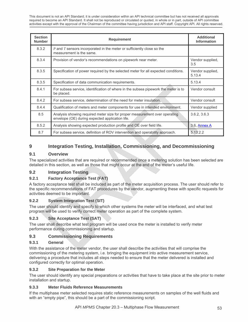
This document is not an API Standard; it is under consideration within an API technical committee but has not received all approvals required to become an API Standard. It shall not be reproduced or circulated or quoted, in whole or in part, outside of API committee activities except with the approval of the Chairman of the committee having jurisdiction and API staff. Copyright API. All rights reserved.
API MPMS Chapter 20.3 – Multiphase Flow Measurement 53
Section Number
Requirement Additional
Information
8.3.2 P and T sensors incorporated in the meter or sufficiently close so the measurement is the same.
8.3.4 Provision of vendor’s recommendations on pipework near meter. Vendor supplied, 3.5
8.3.5 Specification of power required by the selected meter for all expected conditions. Vendor supplied, 5.13.4
8.3.5 Specification of data communication requirements. 5.13.4
8.4.1 For subsea service, identification of where in the subsea pipework the meter is to be placed.
Vendor consult
8.4.2 For subsea service, determination of the need for meter insulation. Vendor consult
8.4.4 Qualification of meters and meter components for use in intended environment. Vendor supplied
8.5 Analysis showing required meter size for proper measurement over operating envelope (OE) during expected application life.
3.6.2, 3.6.3
8.5.2 Analysis showing expected production profile and OE over field life. 3.6, Annex A
8.7 For subsea service, definition of ROV intervention and operability approach. 5.13.2.2
9 Integration Testing, Installation, Commissioning, and Decommissioning
9.1 Overview The specialized activities that are required or recommended once a metering solution has been selected are detailed in this section, as well as those that might occur at the end of the meter’s useful life.
9.2 Integration Testing 9.2.1 Factory Acceptance Test (FAT)
A factory acceptance test shall be included as part of the meter acquisition process. The user should refer to the specific recommendations of FAT procedures by the vendor, augmenting these with specific requests for activities deemed to be important.
9.2.2 System Integration Test (SIT)
The user should identify and specify to which other systems the meter will be interfaced, and what test program will be used to verify correct meter operation as part of the complete system.
9.2.3 Site Acceptance Test (SAT)
The user shall describe what test program will be used once the meter is installed to verify meter performance during commissioning and startup.
9.3 Commissioning Requirements 9.3.1 General
With the assistance of the meter vendor, the user shall describe the activities that will comprise the commissioning of the metering system, i.e. bringing the equipment into active measurement service, delivering a procedure that includes all steps needed to ensure that the meter delivered is installed and configured correctly for optimal operation.
9.3.2 Site Preparation for the Meter
The user should identify any special preparations or activities that have to take place at the site prior to meter installation and startup.
9.3.3 Meter Fluids Reference Measurements
If the multiphase meter selected requires static reference measurements on samples of the well fluids and with an “empty pipe”, this should be a part of the commissioning script.
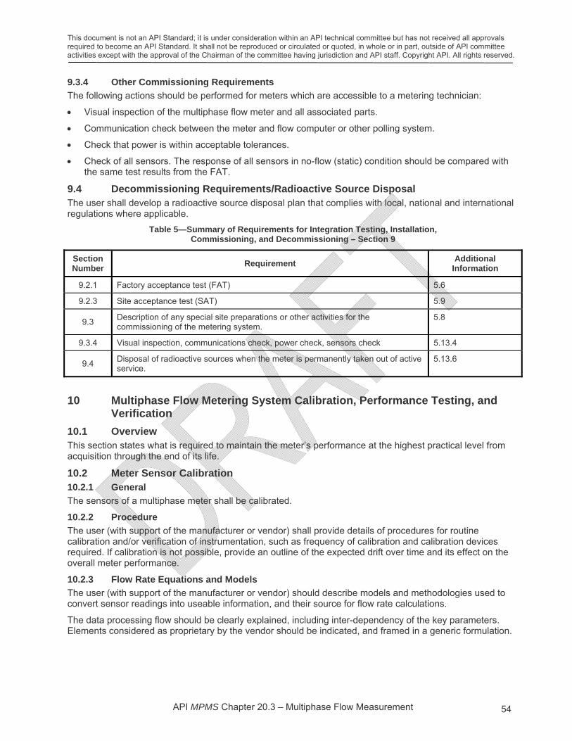
This document is not an API Standard; it is under consideration within an API technical committee but has not received all approvals required to become an API Standard. It shall not be reproduced or circulated or quoted, in whole or in part, outside of API committee activities except with the approval of the Chairman of the committee having jurisdiction and API staff. Copyright API. All rights reserved.
API MPMS Chapter 20.3 – Multiphase Flow Measurement 54
9.3.4 Other Commissioning Requirements
The following actions should be performed for meters which are accessible to a metering technician:
Visual inspection of the multiphase flow meter and all associated parts.
Communication check between the meter and flow computer or other polling system.
Check that power is within acceptable tolerances.
Check of all sensors. The response of all sensors in no-flow (static) condition should be compared with the same test results from the FAT.
9.4 Decommissioning Requirements/Radioactive Source Disposal The user shall develop a radioactive source disposal plan that complies with local, national and international regulations where applicable.
Table 5—Summary of Requirements for Integration Testing, Installation, Commissioning, and Decommissioning – Section 9
Section Number
Requirement Additional
Information
9.2.1 Factory acceptance test (FAT) 5.6
9.2.3 Site acceptance test (SAT) 5.9
9.3 Description of any special site preparations or other activities for the commissioning of the metering system.
5.8
9.3.4 Visual inspection, communications check, power check, sensors check 5.13.4
9.4 Disposal of radioactive sources when the meter is permanently taken out of active service.
5.13.6
10 Multiphase Flow Metering System Calibration, Performance Testing, and Verification
10.1 Overview This section states what is required to maintain the meter’s performance at the highest practical level from acquisition through the end of its life.
10.2 Meter Sensor Calibration 10.2.1 General
The sensors of a multiphase meter shall be calibrated.
10.2.2 Procedure
The user (with support of the manufacturer or vendor) shall provide details of procedures for routine calibration and/or verification of instrumentation, such as frequency of calibration and calibration devices required. If calibration is not possible, provide an outline of the expected drift over time and its effect on the overall meter performance.
10.2.3 Flow Rate Equations and Models
The user (with support of the manufacturer or vendor) should describe models and methodologies used to convert sensor readings into useable information, and their source for flow rate calculations.
The data processing flow should be clearly explained, including inter-dependency of the key parameters. Elements considered as proprietary by the vendor should be indicated, and framed in a generic formulation.

This document is not an API Standard; it is under consideration within an API technical committee but has not received all approvals required to become an API Standard. It shall not be reproduced or circulated or quoted, in whole or in part, outside of API committee activities except with the approval of the Chairman of the committee having jurisdiction and API staff. Copyright API. All rights reserved.
API MPMS Chapter 20.3 – Multiphase Flow Measurement 55
10.3 Meter Reference Facility Flow Testing 10.3.1 Reference Facility Testing
10.3.1.1 General
Reference flow loop testing shall be performed on at least one multiphase flow meter representative of those to be used in a field application, in flow conditions designed to represent the field application as much as possible. The deviations between the two sets of conditions should be explained, and the impact on the performance of the meter assessed. The flow loop test shall be witnessed by a third party. A third party in this context means a representative other than the manufacturer and is open to all relevant parties. It is not uncommon for meters tested on previous installations with technically defensible similar fluid conditions to be used as a type test for future installations.
A key consideration in the selection of a reference test facility is its suitability for the intended application. Independent flow loops should be selected where possible.
10.3.1.2 Requirements of Flow Test Facilities
The multiphase reference flow facility shall regularly calibrate its sensors in a traceable manner.
The flow test facility shall state each of the phase-rate uncertainties attributable to the flow loop, with an explanation of their source in terms of the individual uncertainties in measurement of its fluid properties, reference meters, and other instruments.
The flow test facility should provide evidence that any gas-liquid mass transfer between reference and test measurement points is accounted for during the testing activities.
Any difference in pressure and temperature conditions between the reference measurements and the test meter shall be accounted for.
10.3.2 Meter Flow Rate Performance Tests
10.3.2.1 Multiphase Flow Loop – Test Matrix
The user shall project the anticipated lifetime well production profile and meter operating envelope (OE) and use these to design the flow conditions for the meter flow test. An example matrix is contained in Annex A. Sensitivity to fluid properties, e.g. salinity etc. should also be a part of the test matrix.
10.3.2.2 Blind Tests
Once the manufacturer has completed the meter configuration, flow loop tests shall proceed to conclusion without further intervention. This is commonly called a “blind test” or “out of the box”.
NOTE Performing similar tests at the same flow loop prior to a performance capability acceptance test where the manufacturer uses the data gathered to adjust the meter's response, is considered not a blind test. Furthermore, it makes the case that the metering system requires in-situ calibration in order to achieve the expected performance level. Actual in-situ calibration of multiphase meters is rarely possible.
10.3.2.3 Empty Pipe, Oil-Filled, Water-Filled Tests
When nuclear densitometers are used, a static tests of meters should be made with the meter filled with gas (air) and if required also with oil, and water. The results should be recorded prior to the start of flow testing.
10.4 Field Verification 10.4.1 General
The user shall provide a plan for continual verification of multiphase meters in the field application.
10.4.2 Field Verification Methods
The following are examples of methods that can be useful in field meter verification.
The user can utilize meter diagnostics for verification, both continuously and as part of routine maintenance.
Field comparison of meter outputs with other field measurement systems can be carried out (e.g. use of topside separators).
System balance can be used to verify performance. Balance is discussed in Section 5.10.3.
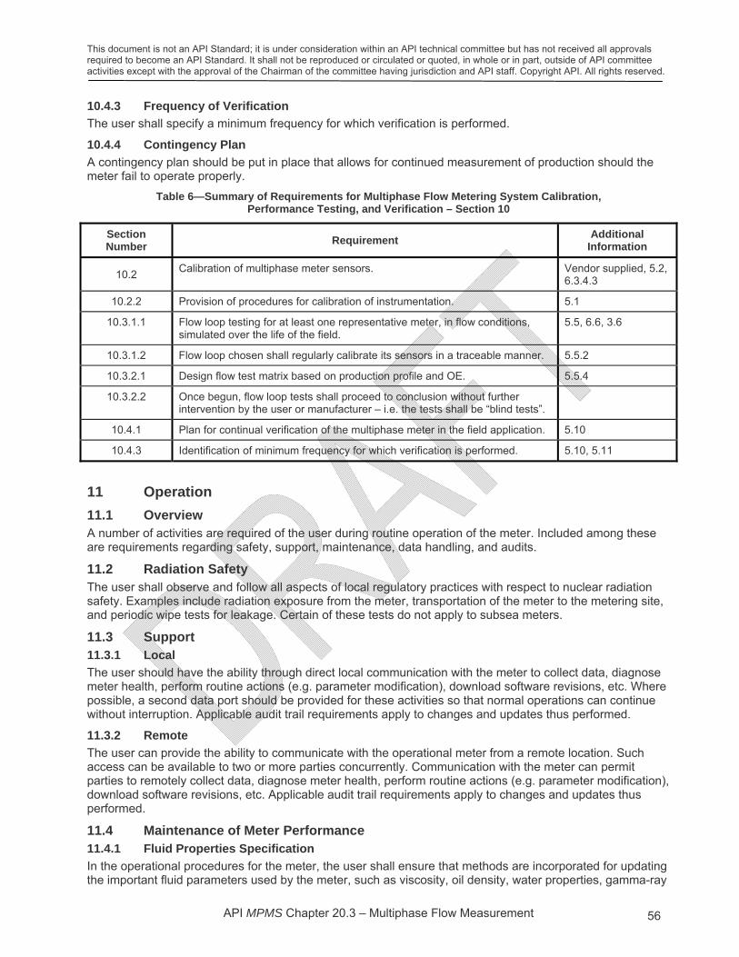
This document is not an API Standard; it is under consideration within an API technical committee but has not received all approvals required to become an API Standard. It shall not be reproduced or circulated or quoted, in whole or in part, outside of API committee activities except with the approval of the Chairman of the committee having jurisdiction and API staff. Copyright API. All rights reserved.
API MPMS Chapter 20.3 – Multiphase Flow Measurement 56
10.4.3 Frequency of Verification
The user shall specify a minimum frequency for which verification is performed.
10.4.4 Contingency Plan
A contingency plan should be put in place that allows for continued measurement of production should the meter fail to operate properly.
Table 6—Summary of Requirements for Multiphase Flow Metering System Calibration, Performance Testing, and Verification – Section 10
Section Number
Requirement Additional
Information
10.2 Calibration of multiphase meter sensors. Vendor supplied, 5.2,
6.3.4.3
10.2.2 Provision of procedures for calibration of instrumentation. 5.1
10.3.1.1 Flow loop testing for at least one representative meter, in flow conditions, simulated over the life of the field.
5.5, 6.6, 3.6
10.3.1.2 Flow loop chosen shall regularly calibrate its sensors in a traceable manner. 5.5.2
10.3.2.1 Design flow test matrix based on production profile and OE. 5.5.4
10.3.2.2 Once begun, flow loop tests shall proceed to conclusion without further intervention by the user or manufacturer – i.e. the tests shall be “blind tests”.
10.4.1 Plan for continual verification of the multiphase meter in the field application. 5.10
10.4.3 Identification of minimum frequency for which verification is performed. 5.10, 5.11
11 Operation
11.1 Overview A number of activities are required of the user during routine operation of the meter. Included among these are requirements regarding safety, support, maintenance, data handling, and audits.
11.2 Radiation Safety The user shall observe and follow all aspects of local regulatory practices with respect to nuclear radiation safety. Examples include radiation exposure from the meter, transportation of the meter to the metering site, and periodic wipe tests for leakage. Certain of these tests do not apply to subsea meters.
11.3 Support 11.3.1 Local
The user should have the ability through direct local communication with the meter to collect data, diagnose meter health, perform routine actions (e.g. parameter modification), download software revisions, etc. Where possible, a second data port should be provided for these activities so that normal operations can continue without interruption. Applicable audit trail requirements apply to changes and updates thus performed.
11.3.2 Remote
The user can provide the ability to communicate with the operational meter from a remote location. Such access can be available to two or more parties concurrently. Communication with the meter can permit parties to remotely collect data, diagnose meter health, perform routine actions (e.g. parameter modification), download software revisions, etc. Applicable audit trail requirements apply to changes and updates thus performed.
11.4 Maintenance of Meter Performance 11.4.1 Fluid Properties Specification
In the operational procedures for the meter, the user shall ensure that methods are incorporated for updating the important fluid parameters used by the meter, such as viscosity, oil density, water properties, gamma-ray

This document is not an API Standard; it is under consideration within an API technical committee but has not received all approvals required to become an API Standard. It shall not be reproduced or circulated or quoted, in whole or in part, outside of API committee activities except with the approval of the Chairman of the committee having jurisdiction and API staff. Copyright API. All rights reserved.
API MPMS Chapter 20.3 – Multiphase Flow Measurement 57
attenuations, oil/gas composition, etc., if and when this is necessary. The user should describe procedures to be followed for ensuring that fluid properties are updated in a manner satisfactory for the application for which the meter is to be used, and guidelines for determining the frequency at which such updating should occur.
11.4.2 Hardware Maintenance
11.4.2.1 Calibration/Verification of Sensors
The user shall ensure that procedures are in place for calibrating essential sensors, except in the case of subsea meters, for which other means of verification may apply. The user should perform in-situ tests that verify the “zero” condition of a sensor, e.g. empty-pipe for gamma radiation sensors, no-flow for DP sensors, etc.
11.4.2.2 Inspection of Instrumentation
Where practical, the user should perform periodic inspection of measurement instrumentation.
11.4.2.3 Radioactive Source Decay Compensation
If a radioactive source is used in the measurement, the user shall describe, on the recommendation of vendor, whether measures need to be undertaken to account for the natural decay in source strength, and if so, how this should be accomplished and how frequently it should be done. If source strength decay is accounted for in the acquisition system, this should be stated.
11.4.3 Software
Data collection and calculation software is considered an integral part of the multiphase meter. All software changes should be carefully considered. Further, all software changes shall be thoroughly tested and validated prior to implementation. All software changes that impact the flow calculations shall be appropriately controlled and documented for audit purposes. Any software upgrade should be backward compatible to ensure proper auditing.
11.4.4 Alarms and Diagnostics
The vendor shall provide a detailed list of alarms created by the multiphase flow meter and the meaning of each. Diagnostic methods that can be used to assist the user should be fully documented.
11.4.5 Preventive Maintenance
Methods and techniques used to keep the meter in proper working order should be detailed.
11.4.6 Accessibility
The user should ensure that the meter is installed in such a way that it can be accessed for maintenance. For subsea applications, the user should consider meter retrievability.
11.5 Data 11.5.1 Acquired Data Set
The user should specify minimum data sets, both raw and processed, to be acquired from the meter in routine operation, as well as in diagnostic modes. All data sets shall be time stamped.
11.5.2 Integrity
The user should ensure that normal methods are used to maintain data integrity in communication and storage.
11.5.3 Format
The user should specify data formats to be used, employing industry standard data formats wherever possible.
11.5.4 Frequency
The user should specify the frequency at which data are acquired from the meter, and at which the data are collected by supervisory control and data acquisition (SCADA) or other data storage system.

This document is not an API Standard; it is under consideration within an API technical committee but has not received all approvals required to become an API Standard. It shall not be reproduced or circulated or quoted, in whole or in part, outside of API committee activities except with the approval of the Chairman of the committee having jurisdiction and API staff. Copyright API. All rights reserved.
API MPMS Chapter 20.3 – Multiphase Flow Measurement 58
11.5.5 Access Control (Security)
The user shall limit access to the meter to only those personnel authorized to do so, and ensure that a history of all access is recorded.
11.5.6 Storage
The user should store essential information in non-volatile memory for recovery in case of power failure. Raw data should be stored for the maximum period possible for later re-computation.
11.6 Audit Trail The user shall preserve an audit trail of data, alarm, and event information.
Table 7—Summary of Requirements and Recommendations for Operation – Section 11
Section Number
Requirement Additional
Information
11.2 Radiation safety compliance with all aspects of local regulatory practices 7.1
11.4.1 Methods incorporated for updating important fluid parameters such as viscosity, oil density, water salinity, gamma-ray attenuations, oil/gas composition.
Vendor supplied, 5.11
11.4.2.1 Procedures for calibrating essential sensors. Vendor supplied, 5.2, 6.3.4.3
11.4.2.3 Procedures to account for natural decay in source strength. 4.1.2.1.4
11.4.3 Thorough test and validation of all software changes prior to implementation, appropriately controlled and documented for audit purposes.
Vendor supplied, 5.13.5
11.4.4 List of alarms created by the multiphase or wet-gas flow meter. Vendor supplied, 5.13.5
11.5.5 Access to the meter only by authorized personnel.
11.6 Audit trail of all necessary information. 5.13.5

This document is not an API Standard; it is under consideration within an API technical committee but has not received all approvals required to become an API Standard. It shall not be reproduced or circulated or quoted, in whole or in part, outside of API committee activities except with the approval of the Chairman of the committee having jurisdiction and API staff. Copyright API. All rights reserved.
API MPMS Chapter 20.3 – Multiphase Flow Measurement 59
Annex A (informative)
Example Template for MPFM Selection

This document is not an API Standard; it is under consideration within an API technical committee but has not received all approvals required to become an API Standard. It shall not be reproduced or circulated or quoted, in whole or in part, outside of API committee activities except with the approval of the Chairman of the committee having jurisdiction and API staff. Copyright API. All rights reserved.
API MPMS Chapter 20.3 – Multiphase Flow Measurement 60
Annex B (informative)
Typical MPFM Reports
B.1. Inspection and Calibration Report
When the user is accepting a meter purchased from a vendor, it is common practice to inspect the product at the vendor’s site, and to witness certain basic measurements associated with the meter. At the conclusion of these activities, the vendor will normally provide a report of these activities to the user.
Because no two meters are exactly alike and depend on the use of a variety of sensors and models, the exact details in any report will vary dependent on the manufacturer and on the particular kind of meter under inspection. The following is an example of such a report for a dual-energy gamma/Venturi meter.
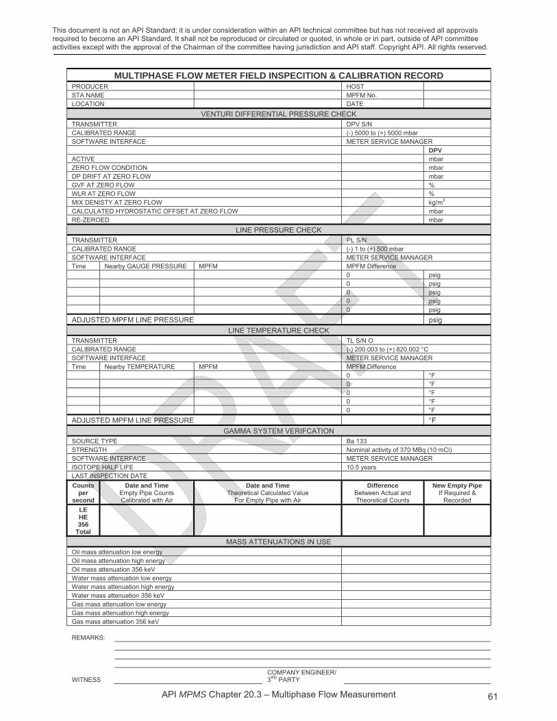
This document is not an API Standard; it is under consideration within an API technical committee but has not received all approvals required to become an API Standard. It shall not be reproduced or circulated or quoted, in whole or in part, outside of API committee activities except with the approval of the Chairman of the committee having jurisdiction and API staff. Copyright API. All rights reserved.
API MPMS Chapter 20.3 – Multiphase Flow Measurement 61
MULTIPHASE FLOW METER FIELD INSPECITION & CALIBRATION RECORD PRODUCER HOST STA NAME MPFM No. LOCATION DATE
VENTURI DIFFERENTIAL PRESSURE CHECK TRANSMITTER DPV S/N CALIBRATED RANGE (-) 5000 to (+) 5000 mbar SOFTWARE INTERFACE METER SERVICE MANAGER DPV ACTIVE mbar ZERO FLOW CONDITION mbar DP DRIFT AT ZERO FLOW mbar GVF AT ZERO FLOW % WLR AT ZERO FLOW % MIX DENISTY AT ZERO FLOW kg/m3 CALCULATED HYDROSTATIC OFFSET AT ZERO FLOW mbar RE-ZEROED mbar
LINE PRESSURE CHECK TRANSMITTER PL S/N CALIBRATED RANGE (-) 1 to (+) 500 mbar SOFTWARE INTERFACE METER SERVICE MANAGER Time Nearby GAUGE PRESSURE MPFM MPFM Difference 0 psig 0 psig 0 psig 0 psig 0 psig
ADJUSTED MPFM LINE PRESSURE psig
LINE TEMPERATURE CHECK TRANSMITTER TL S/N O CALIBRATED RANGE (-) 200.003 to (+) 820.002 °C SOFTWARE INTERFACE METER SERVICE MANAGER Time Nearby TEMPERATURE MPFM MPFM Difference 0 °F 0 °F 0 °F 0 °F 0 °F
ADJUSTED MPFM LINE PRESSURE °F
GAMMA SYSTEM VERIFCATION SOURCE TYPE Ba 133 STRENGTH Nominal activity of 370 MBq (10 mCi) SOFTWARE INTERFACE METER SERVICE MANAGER ISOTOPE HALF LIFE 10.5 years LAST INSPECTION DATE
Counts per
second
Date and Time Empty Pipe Counts Calibrated with Air
Date and Time Theoretical Calculated Value
For Empty Pipe with Air
Difference Between Actual and Theoretical Counts
New Empty Pipe If Required &
Recorded
LE HE 356
Total
MASS ATTENUATIONS IN USE Oil mass attenuation low energy Oil mass attenuation high energy Oil mass attenuation 356 keV Water mass attenuation low energy Water mass attenuation high energy Water mass attenuation 356 keV Gas mass attenuation low energy Gas mass attenuation high energy Gas mass attenuation 356 keV REMARKS:
WITNESS COMPANY ENGINEER/
3RD PARTY

This document is not an API Standard; it is under consideration within an API technical committee but has not received all approvals required to become an API Standard. It shall not be reproduced or circulated or quoted, in whole or in part, outside of API committee activities except with the approval of the Chairman of the committee having jurisdiction and API staff. Copyright API. All rights reserved.
API MPMS Chapter 20.3 – Multiphase Flow Measurement 62
B.2. Commissioning Report
Once the user has accepted a meter purchased from a vendor, it will then be delivered to the operational site for integration into the user’s production system. Prior to the use of the meter in normal operations, it is common practice for the user to observe certain aspects of the product’s performance at the operational site, and to formally acknowledge that the measurements recorded were indeed made. This activity is called meter commissioning.
At the conclusion of these activities, the vendor will normally provide a report of all measurements and other relevant events to the user.
Because no two meters are exactly alike and because they use a variety of sensors and models, the exact details in any commissioning report will vary dependent on the manufacturer and on the particular kind of meter that is being commissioned.
The following is an example of a portion of a commissioning report for a dual-energy gamma/Venturi meter.
On Site Commissioning Procedure
For Meter XXXX
No. Rev: Date: Page:
SYSTEM SETUP CHECK LIST RECORD
SOFTWARE RECORDS
Description Value Sign
Record the Service Manager version (also in top of window) Press ʺHelp -> Aboutʺ to view Version:…………………………………
Record the Software key Press ʺHelp -> Aboutʺ to view Key: ………………………………
SYSTEM ALARM LIMITS
Description Unit Default Value Actual Value Sign
Input Voltage – high Volt 30
Input Voltage – low Volt 12
ISO supply voltage – high Volt 30
ISO supply voltage – low Volt 20
Temperature – high °C 85
Temperature – low °C –40
Humidity – high %RH 100
Humidity – low %RH 0
DYNAMIC DP LIMITS
Description Unit Default Value Actual Value Sign
Low alarm limit mbar 50
Cut of value mbar 5
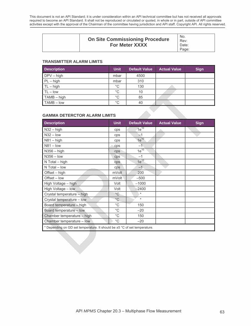
This document is not an API Standard; it is under consideration within an API technical committee but has not received all approvals required to become an API Standard. It shall not be reproduced or circulated or quoted, in whole or in part, outside of API committee activities except with the approval of the Chairman of the committee having jurisdiction and API staff. Copyright API. All rights reserved.
API MPMS Chapter 20.3 – Multiphase Flow Measurement 63
On Site Commissioning Procedure
For Meter XXXX
No. Rev: Date: Page:
TRANSMITTER ALARM LIMITS
Description Unit Default Value Actual Value Sign
DPV – high mbar 4500
PL – high mbar 310
TL – high °C 130
TL – low °C 10
TAMB – high °C 85
TAMB – low °C 40
GAMMA DETERCTOR ALARM LIMITS
Description Unit Default Value Actual Value Sign
N32 – high cps 1e10
N32 – low cps –1
N81 – high cps 1e10
N81 – low cps –1
N356 – high cps 1e10
N356 – low cps –1
N Total – high cps 1e10
N Total – low cps –1
Offset – high mVolt 200
Offset – low mVolt –500
High Voltage – high Volt –1000
High Voltage – low Volt –2400
Crystal temperature – high °C *
Crystal temperature – low °C *
Board temperature – high °C 150
Board temperature – low °C –20
Chamber temperature – high °C 150
Chamber temperature – low °C –20
* Depending on GD set temperature. It should be ±5 °C of set temperature.

This document is not an API Standard; it is under consideration within an API technical committee but has not received all approvals required to become an API Standard. It shall not be reproduced or circulated or quoted, in whole or in part, outside of API committee activities except with the approval of the Chairman of the committee having jurisdiction and API staff. Copyright API. All rights reserved.
API MPMS Chapter 20.3 – Multiphase Flow Measurement 64
On Site Commissioning Procedure
For Meter XXXX
No. Rev: Date: Page:
PROCESSED DATA CHECK LIST RECORD
Verify data processed in MPFM to client control system. Compare data shown in MPFM software and data presented in client control system. DAFC simulation mode can be utilized for this purpose.
Verify correctly presented data with ranges and units, unless customized units are enabled.
Tag Description Tag Value in MPFM
Value in Control System
Sign
Meter: alarm register n/a
Spare n/a
Venturi differential pressure – DP DPV
Line Pressure PL
Line Temperature TL
Vol flow of oil, line cond qo_lc
Vol flow of water, line cond qw_lc
Vol flow of gas, line cond qg_lc
Vol flow of oil, std cond qo_sc
Vol flow of water, std cond qw_sc
Vol flow of gas, std cond qg_sc
Vol fraction of oil, line cond Fo_lc
Vol fraction of water, line cond Fw_lc
Vol fraction of gas, line cond Fg_lc
Vol fraction of oil, std cond Fo_sc
Vol fraction of water, std cond Fw_sc
Vol fraction of gas, std cond Fg_sc
Mass flow of oil, line cond mo_lc
Mass flow of water, line cond mw_lc
Mass flow of gas, line cond mg_lc
Mass flow of oil, std cond mo_sc
Mass flow of water, std cond mw_sc
Mass flow of gas, std cond mg_sc
Total mass flow m_lc
Vol flow of oil, std cond, no phase transfer
qo_scnp
Vol flow of water, std cond, no phase transfer
qw_scnp
Vol flow of gas, std cond, no phase transfer
qg_scnp
Start time cumulative values: Seconds n/a
Start time cumulative values: Minutes n/a
Start time cumulative values: Hours n/a
Start time cumulative values: Day n/a
Start time cumulative values: Month n/a
Start time cumulative values: Year n/a
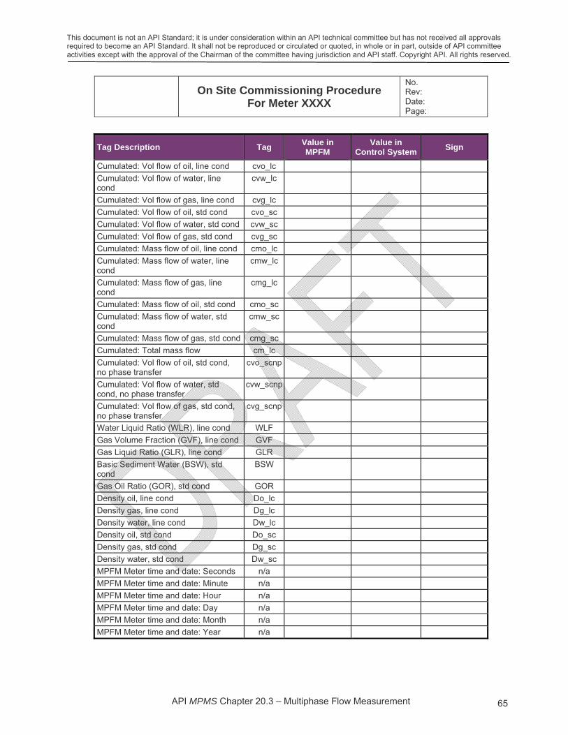
This document is not an API Standard; it is under consideration within an API technical committee but has not received all approvals required to become an API Standard. It shall not be reproduced or circulated or quoted, in whole or in part, outside of API committee activities except with the approval of the Chairman of the committee having jurisdiction and API staff. Copyright API. All rights reserved.
API MPMS Chapter 20.3 – Multiphase Flow Measurement 65
On Site Commissioning Procedure
For Meter XXXX
No. Rev: Date: Page:
Tag Description Tag Value in MPFM
Value in Control System
Sign
Cumulated: Vol flow of oil, line cond cvo_lc
Cumulated: Vol flow of water, line cond
cvw_lc
Cumulated: Vol flow of gas, line cond cvg_lc
Cumulated: Vol flow of oil, std cond cvo_sc
Cumulated: Vol flow of water, std cond cvw_sc
Cumulated: Vol flow of gas, std cond cvg_sc
Cumulated: Mass flow of oil, line cond cmo_lc
Cumulated: Mass flow of water, line cond
cmw_lc
Cumulated: Mass flow of gas, line cond
cmg_lc
Cumulated: Mass flow of oil, std cond cmo_sc
Cumulated: Mass flow of water, std cond
cmw_sc
Cumulated: Mass flow of gas, std cond cmg_sc
Cumulated: Total mass flow cm_lc
Cumulated: Vol flow of oil, std cond, no phase transfer
cvo_scnp
Cumulated: Vol flow of water, std cond, no phase transfer
cvw_scnp
Cumulated: Vol flow of gas, std cond, no phase transfer
cvg_scnp
Water Liquid Ratio (WLR), line cond WLF
Gas Volume Fraction (GVF), line cond GVF
Gas Liquid Ratio (GLR), line cond GLR
Basic Sediment Water (BSW), std cond
BSW
Gas Oil Ratio (GOR), std cond GOR
Density oil, line cond Do_lc
Density gas, line cond Dg_lc
Density water, line cond Dw_lc
Density oil, std cond Do_sc
Density gas, std cond Dg_sc
Density water, std cond Dw_sc
MPFM Meter time and date: Seconds n/a
MPFM Meter time and date: Minute n/a
MPFM Meter time and date: Hour n/a
MPFM Meter time and date: Day n/a
MPFM Meter time and date: Month n/a
MPFM Meter time and date: Year n/a

This document is not an API Standard; it is under consideration within an API technical committee but has not received all approvals required to become an API Standard. It shall not be reproduced or circulated or quoted, in whole or in part, outside of API committee activities except with the approval of the Chairman of the committee having jurisdiction and API staff. Copyright API. All rights reserved.
API MPMS Chapter 20.3 – Multiphase Flow Measurement 66
On Site Commissioning Procedure
For Meter XXXX
No. Rev: Date: Page:
Tag Description Tag Value in MPFM
Value in Control System
Sign
MPFM Meter: Well profile n/a
N32 – Average n/a
N81 – Average n/a
N356 – Average n/a
NTotal – Average n/a
Spare n/a
… n/a
Spare n/a
Totalized oil standard conditions n/a
Oil produced previous 24 hours standard conditions
n/a
Oil produced current 24 hours standard conditions
n/a
Totalized water standard conditions n/a
Water produced previous 24 hours standard conditions
n/a
Water produced current 24 hours standard conditions
n/a
Totalized gas standard conditions n/a
Gas produced previous 24 hours standard conditions
n/a
Gas produced current 24 hours standard conditions
n/a
Totalized oil line conditions
Oil produced previous 24 hours line conditions
Oil produced current 24 hours line conditions
Totalized water line conditions
Water produced previous 24 hours line conditions
Water produced current 24 hours line conditions
Totalized gas line conditions
Gas produced previous 24 hours line conditions
Gas produced current 24 hours line conditions
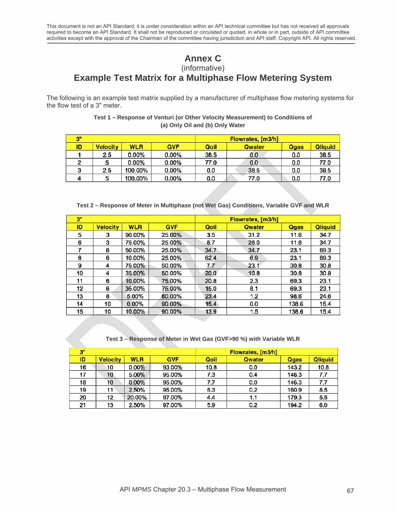
This document is not an API Standard; it is under consideration within an API technical committee but has not received all approvals required to become an API Standard. It shall not be reproduced or circulated or quoted, in whole or in part, outside of API committee activities except with the approval of the Chairman of the committee having jurisdiction and API staff. Copyright API. All rights reserved.
API MPMS Chapter 20.3 – Multiphase Flow Measurement 67
Annex C (informative)
Example Test Matrix for a Multiphase Flow Metering System
The following is an example test matrix supplied by a manufacturer of multiphase flow metering systems for the flow test of a 3" meter.
Test 1 – Response of Venturi (or Other Velocity Measurement) to Conditions of (a) Only Oil and (b) Only Water
Test 2 – Response of Meter in Multiphase (not Wet Gas) Conditions, Variable GVF and WLR
Test 3 – Response of Meter in Wet Gas (GVF>90 %) with Variable WLR

This document is not an API Standard; it is under consideration within an API technical committee but has not received all approvals required to become an API Standard. It shall not be reproduced or circulated or quoted, in whole or in part, outside of API committee activities except with the approval of the Chairman of the committee having jurisdiction and API staff. Copyright API. All rights reserved.
API MPMS Chapter 20.3 – Multiphase Flow Measurement 68
Bibliography
[1] API Recommended Practice 2A, Planning, Designing, and Constructing Fixed Offshore Platforms
[2] API Specification 6A/ISO 10423, Specification for Wellhead and Christmas Tree Equipment
[3] API Recommended Practice 17A/ISO 13628:2005, Design and Operation of Subsea Production Systems—General Requirements and Recommendations
[4] API Specification 17D, Subsea Wellhead and Christmas Tree Equipment
[5] API Specification 17F/ISO 13628-6:2006, Specification for Subsea Production Control Systems
[6] API Recommended Practice 17N/ISO 13628, Subsea Production System Reliability and Technical Risk Management
[7] API Recommended Practice 85, Use of Subsea Wet-Gas Flowmeters in Allocation Measurement Systems
[8] API Recommended Practice 86-2005, Measurement of Multiphase Flow
[9] API MPMS Chapter 14.3 (all parts), Natural Gas Fluids Measurement – Concentric, Square-Edged Orifice Meters
[10] API Publication 2566-2004, State of the Art Multiphase Flow Metering
[11] AGA Report No. 8, Compressibility Factors of Natural Gas and Other Related Hydrocarbon Gases
[12] ASME MFC-19G-2008, Wet Gas Flow Metering Guideline (Technical Report)
[13] GPA Standard 2145-09, Table of Physical Properties for Hydrocarbons and Other Compounds of Interest to the Natural Gas Industry
[14] ISO/IEC Guide 98-3:2008, Uncertainty of measurement — Part 3: Guide to the expression of uncertainty in measurement (GUM:1995)
[15] ISO/IEC Guide 98-3:2008/Suppl.1:2008, Propagation of distributions using a Monte Carlo method
[16] ISO 5167:2003 (all parts), Measurement of fluid flow by means of pressure differential devices inserted in circular cross-section conduits running full
[17] ISO/TR 5168:2005, Measurement of fluid flow — Procedures for the evaluation of uncertainties
[18] Paris, N., and Miller, G., “The Application of Multiphase Flow Meters in the Development of Oil with Emulsion Forming Tendency”, SE Asia Flow Measurement Workshop, Kuala Lumpur, Malaysia
[19] Basil, M., Stobie, G., and Letton, C., “A New Approach to MPFM Performance Assessment in Heavy Oil”, North Sea Flow Measurement Workshop, 16 – 19 October, 2007, Oslo, Norway
[20] Caetano, E., Pinheiro, J.A., Silva, C.B., Kuchpil, C., and E. Dykesteen, “Operational Experience with Subsea Multiphase Flow Meter”, North Sea Flow Measurement Workshop, Gleneagles, Scotland, October 2000
[21] Wee, A., Skjældal, I.M., and Øystein Lund Bø, “Multiphase Metering with Early Detection of Changes in Water Salinity”, The Americas Workshop, Houston, Texas, February 2009
[22] Scheers, A.M., Halvorsen, M., Wideroe, T., and P. Nardi, “Extending the Multi-phase Flow Meter operating envelope by adding a partial separation device”, South East Asia Hydrocarbon Measurement Workshop, Kuala Lumpur, March 2005
[23] Ashton, S.L., Cutmore, N.G., Roach, G.J., Watt, J.S., Zastawny, H.W., and A.J. McEwan, “Development And Trial Of Microwave Techniques For Measurement Of Multiphase Flow Of Oil, Water And Gas”, SPE Asia Pacific Oil and Gas Conference, Melbourne, Australia, November 1994
[24] Tuss, B., Perry, D., and G. Shoup, “Field Tests of the High Gas Volume Fraction Multiphase Meter”, SPE Annual Technical Conference and Exhibition, October 1996

This document is not an API Standard; it is under consideration within an API technical committee but has not received all approvals required to become an API Standard. It shall not be reproduced or circulated or quoted, in whole or in part, outside of API committee activities except with the approval of the Chairman of the committee having jurisdiction and API staff. Copyright API. All rights reserved.
API MPMS Chapter 20.3 – Multiphase Flow Measurement 69
[25] Norwegian Society for Oil and Gas Measurement, (Norsk Foreing for Olje og Gassmåling), NFOGM, “Handbook of Multiphase Flow Metering”, second edition, March 2005
[26] UK Department of Trade and Industry, “Guidance Notes for Petroleum Measurement”, Issue 7, December 2003, http://www.bis.gov.uk/