apm system installation manual - pdf.textfiles.compdf.textfiles.com/manuals/telecom-f-r/nec...
TRANSCRIPT

APM SYSTEM
Installation Manual
NEC America, Inc.
NDA-30025-004Revision 4.0April, 1998
Stock # 241737

LIABILITY DISCLAIMER
NEC America reserves the right to change the specifications, functions, or features in this document at any time without notice. NEC America has prepared this document for use by its employees and customers. The information contained herein is the property of NEC America and shall not be reproduced without prior written approval from NEC America.
Copyright 1997
NEC America, Inc.

APM System Installation Manual CONTENTS
TABLE OF CONTENTSPage
Chapter 1 - INTRODUCTION . . . . . . . . . . . . . . . . . . . . . . . . . . . . . . . . . . . . . . . . . . . . . . . 1Typical UAP . . . . . . . . . . . . . . . . . . . . . . . . . . . . . . . . . . . . . . . . . . . . . . . . . . . . . . . . . . . . . . . . . . 1Sequential Step-by-Step Process . . . . . . . . . . . . . . . . . . . . . . . . . . . . . . . . . . . . . . . . . . . . . . . . . . 2Sequential Organization of Manual. . . . . . . . . . . . . . . . . . . . . . . . . . . . . . . . . . . . . . . . . . . . . . . . . 3Chapter Layout . . . . . . . . . . . . . . . . . . . . . . . . . . . . . . . . . . . . . . . . . . . . . . . . . . . . . . . . . . . . . . . . 3Use of Figures and Typefaces . . . . . . . . . . . . . . . . . . . . . . . . . . . . . . . . . . . . . . . . . . . . . . . . . . . . 4References . . . . . . . . . . . . . . . . . . . . . . . . . . . . . . . . . . . . . . . . . . . . . . . . . . . . . . . . . . . . . . . . . . . 4General Guidelines . . . . . . . . . . . . . . . . . . . . . . . . . . . . . . . . . . . . . . . . . . . . . . . . . . . . . . . . . . . . . 5
Chapter 2 - BASELINE SYSTEM . . . . . . . . . . . . . . . . . . . . . . . . . . . . . . . . . . . . . . . . . . . . 7Introduction . . . . . . . . . . . . . . . . . . . . . . . . . . . . . . . . . . . . . . . . . . . . . . . . . . . . . . . . . . . . . . . . . . . 7Necessary Materials . . . . . . . . . . . . . . . . . . . . . . . . . . . . . . . . . . . . . . . . . . . . . . . . . . . . . . . . . . . . 7Necessary Preparation . . . . . . . . . . . . . . . . . . . . . . . . . . . . . . . . . . . . . . . . . . . . . . . . . . . . . . . . . . 8Installation Procedure . . . . . . . . . . . . . . . . . . . . . . . . . . . . . . . . . . . . . . . . . . . . . . . . . . . . . . . . . . . 8Testing Procedure. . . . . . . . . . . . . . . . . . . . . . . . . . . . . . . . . . . . . . . . . . . . . . . . . . . . . . . . . . . . . . 8
Chapter 3 - SCO UNIX SYSTEM V INSTALLATION . . . . . . . . . . . . . . . . . . . . . . . . . . . . . 9Introduction . . . . . . . . . . . . . . . . . . . . . . . . . . . . . . . . . . . . . . . . . . . . . . . . . . . . . . . . . . . . . . . . . . . 9Necessary Materials . . . . . . . . . . . . . . . . . . . . . . . . . . . . . . . . . . . . . . . . . . . . . . . . . . . . . . . . . . . . 9Necessary Preparation . . . . . . . . . . . . . . . . . . . . . . . . . . . . . . . . . . . . . . . . . . . . . . . . . . . . . . . . . 10Installation Procedure . . . . . . . . . . . . . . . . . . . . . . . . . . . . . . . . . . . . . . . . . . . . . . . . . . . . . . . . . . 10Adding Drivers to UNIX. . . . . . . . . . . . . . . . . . . . . . . . . . . . . . . . . . . . . . . . . . . . . . . . . . . . . . . . . 23
Parallel I/O Device . . . . . . . . . . . . . . . . . . . . . . . . . . . . . . . . . . . . . . . . . . . . . . . . . . . . . . . . . . . 23Second Serial I/O Device. . . . . . . . . . . . . . . . . . . . . . . . . . . . . . . . . . . . . . . . . . . . . . . . . . . . . . 24SCSI Adapter Device . . . . . . . . . . . . . . . . . . . . . . . . . . . . . . . . . . . . . . . . . . . . . . . . . . . . . . . . . 25SCSI Tape Device . . . . . . . . . . . . . . . . . . . . . . . . . . . . . . . . . . . . . . . . . . . . . . . . . . . . . . . . . . . 253C509 Ethernet Device . . . . . . . . . . . . . . . . . . . . . . . . . . . . . . . . . . . . . . . . . . . . . . . . . . . . . . . 27TCP/IP Runtime System . . . . . . . . . . . . . . . . . . . . . . . . . . . . . . . . . . . . . . . . . . . . . . . . . . . . . . 29LLI Drivers . . . . . . . . . . . . . . . . . . . . . . . . . . . . . . . . . . . . . . . . . . . . . . . . . . . . . . . . . . . . . . . . . 31Network Configuration . . . . . . . . . . . . . . . . . . . . . . . . . . . . . . . . . . . . . . . . . . . . . . . . . . . . . . . . 33SunRiver Controller Device . . . . . . . . . . . . . . . . . . . . . . . . . . . . . . . . . . . . . . . . . . . . . . . . . . . . 35
Chapter 4 - APPLICATION MANAGER INSTALLATION . . . . . . . . . . . . . . . . . . . . . . . . 39
Chapter 5 - BACKUP AND RESTORATION PROCEDURES . . . . . . . . . . . . . . . . . . . . . 49Creating Boot and Root Floppy Disks. . . . . . . . . . . . . . . . . . . . . . . . . . . . . . . . . . . . . . . . . . . . . . 49Tape Backup and Restore . . . . . . . . . . . . . . . . . . . . . . . . . . . . . . . . . . . . . . . . . . . . . . . . . . . . . . 50
Backup . . . . . . . . . . . . . . . . . . . . . . . . . . . . . . . . . . . . . . . . . . . . . . . . . . . . . . . . . . . . . . . . . . . . 50Restore . . . . . . . . . . . . . . . . . . . . . . . . . . . . . . . . . . . . . . . . . . . . . . . . . . . . . . . . . . . . . . . . . . . 53
Chapter 6 - TROUBLESHOOTING ISSUES . . . . . . . . . . . . . . . . . . . . . . . . . . . . . . . . . . 57TCP/IP Connectivity to PBX . . . . . . . . . . . . . . . . . . . . . . . . . . . . . . . . . . . . . . . . . . . . . . . . . . . . . 5716 Mbyte RAM . . . . . . . . . . . . . . . . . . . . . . . . . . . . . . . . . . . . . . . . . . . . . . . . . . . . . . . . . . . . . . . 58COM Port Usage. . . . . . . . . . . . . . . . . . . . . . . . . . . . . . . . . . . . . . . . . . . . . . . . . . . . . . . . . . . . . . 59Video Adapter Addressing . . . . . . . . . . . . . . . . . . . . . . . . . . . . . . . . . . . . . . . . . . . . . . . . . . . . . . 59Root File System Recovery . . . . . . . . . . . . . . . . . . . . . . . . . . . . . . . . . . . . . . . . . . . . . . . . . . . . . 59
NDA-30025 Revision 4.0 Page i

CONTENTS APM System Installation Manual
This Page Left Blank.
Page ii NDA-30025 Revision 4.0

APM System Installation Manual FIGURES
LIST OF FIGURESFigure Title Page
1-1 Open Application Interface (OAI) Architecture . . . . . . . . . . . . . . . . . . . . . . . . . . . . . . . 11-2 Sequential Installation Process . . . . . . . . . . . . . . . . . . . . . . . . . . . . . . . . . . . . . . . . . . . 21-3 System Configuration Data Sheet . . . . . . . . . . . . . . . . . . . . . . . . . . . . . . . . . . . . . . . . . 63-1 Initial SCO UNIX Boot Prompt. . . . . . . . . . . . . . . . . . . . . . . . . . . . . . . . . . . . . . . . . . . 103-2 Filesystems Allocation Table. . . . . . . . . . . . . . . . . . . . . . . . . . . . . . . . . . . . . . . . . . . . 16
NDA-30025 Revision 4.0 Page iii

FIGURES APM System Installation Manual
This Page Left Blank.
Page iv NDA-30025 Revision 4.0

APM System Installation Manual INTRODUCTION
Chapter 1 INTRODUCTION
The Open Application Interface (OAI) physical architecture provides a link between the NEC NEAX 2400 switching family and one or more general purpose computers. The general purpose computer, or User Application Processor (UAP) as it is referred to throughout this manual, provides a powerful processing platform for the introduction of new switching features via an Ethernet communication link. Figure 1-1 illustrates the simplicity of this architecture.
Figure 1-1 Open Application Interface (OAI) Architecture
The UAP, equipped with the Application Manager (APM) Platform, provides the necessary system configuration, installation controls, system logging, error recovery management, and communications required to support OAI and non-OAI applications. For complete details of the APM environment, refer to the APM Operations Manual and other OAI-related documentation.
Typical UAP
The following hardware components are required to provide the full functionality of what is referred to in this manual as a “typical UAP”:
• a 386/486/Pentium-based PC
• an Ethernet (TCP/IP) communication card
• a 130 MB or larger hard disk
• a VGA graphics card and color monitor
• a line printer
• the SCO UNIX System V/386 Operating System (OS).
N EC N EA X2400 ICS
U APOAI LinkEthernet
NDA-30025 Revision 4.0 Page 1

INTRODUCTION APM System Installation Manual
This profile of a typical UAP serves as a base of reference for the process of installing the required hardware and software. Any deviation from this system profile or the software associated to it in this manual may result in the need to adapt the instructions provided in this manual. It is important to ensure that the components chosen for installation are supported with manufacturer documentation and software drivers that operate within the SCO UNIX environment.
Sequential Step-by-Step Process
The installation procedures described in this manual are sequential. The success of each step is, in large part, dependent upon the success of the preceding step(s). Therefore, each step in the sequence must be performed completely and tested thoroughly before the next step is begun.
The sequence of steps is shown below in Figure 1-2:
Figure 1-2 Sequential Installation Process
Baseline System
UNIX Operating System
STEP 1This step involves installing the baseline hardware, formatting the harddrive, and configuring the systems internal memory with the correct settings required for the peripherals installed.
STEP 2This step involves installation of the SCO UNIX Operating System which requires preparing the hard disk, defining the file systems, and installing the software.
STEP 3
STEP 4
The APM Platform is installed from floppy disk or cartridge tape. APM Platform
OAI Applications are installed through the APM administration menu (apmadm) using the installation option.
OAI Applications and Packages
Page 2 NDA-30025 Revision 4.0

APM System Installation Manual INTRODUCTION
Sequential Organization of Manual
The chapters in this manual correspond to this sequence of steps.
1. Introduction — This chapter introduces the basic OAI/APM architecture, the requirements of a typical-UAP system, the step-by-step and sequential installation process described in this manual, and useful information on how this manual should be used to assist in the installation process.
2. Baseline System — This chapter supplements manufacturer guides simply by introducing order to the installation of the required hardware and its baseline configuration.
3. Operating System — This chapter supplements manufacturer installation guidelines for SCO UNIX System V/386. The complete installation procedure is presented with the normal decision criteria answered for a typical UAP.
4. APM Platform — This chapter covers the steps necessary to install the APM Platform. This installation represents the heart of the OAI environment. It should not be attempted until the previous components have been installed and tested.
5. Troubleshooting Issues — This chapter discusses a few concerns that may arise during the course of the installation.
Chapter Layout
Each chapter in the sequenced installation process introduces the step discussed in the chapter, discusses any materials or preparation required to perform the step, indicates the necessary status of the system before the step can be performed, presents or refers to a detailed procedural guide to performance of the step, and, in some cases, describes testing methods for verifying success of the installation step. Each chapter, then, contains the following sections:
• Introduction — This section introduces the system component that is covered in the chapter. It also addresses the general purpose of the given component within the scope of the APM Platform.
• Necessary Materials — Specific configuration issues are addressed with suggested parameters for a typical UAP installation. Any installation media and documentation that may be required is identified.
• Necessary Preparation — This section provides a reference for the required status of the UAP before installing the given component. It also discusses any preparations that should be completed before beginning the installation procedure.
• Installation Procedure — A step-by-step installation procedure is provided in this section. Each step is presented under a dedicated subheading with all supporting decision criteria explained and further illustrated in figures that show expected display sequences.
• Optional Testing — Most chapters include simplified test criteria for the given component. In most cases the component installation can be verified by observing the information displayed during a boot process. This section offers the minimal amount of testing that should be completed before going onto the next step.
NDA-30025 Revision 4.0 Page 3

INTRODUCTION APM System Installation Manual
Use of Figures and Typefaces
Throughout this document, figures are used to show actual UAP display sequences, including prompts and user input at those prompts. System-supplied data in these figures is typically represented in plain typeface whereas user-supplied data is represented in boldface type. Wherever user input is variable (i.e., what is shown is only an example), mention is made of that fact in the narrative description that accompanies the display. Partial display sequences are illustrated via incomplete display figures as shown below. Irrelevant or unimportant screen information may be replaced with three vertical dots within a figure to show the incomplete nature of the display.
References
Manufacturer installation guides that are provided with each hardware component should be considered the primary references in the installation of the components which they accompany. The guidelines presented in this manual supplement these documents with supporting procedures and configuration information that must be addressed to meet minimum system requirements. The following documentation should prove most helpful to the installation processes described in this manual:
• NEC America Inc. Documentation
• OAI Module Installation Manual for the NEAX2400 IMS.
• OAI Concept Manual.
• Applications Manager (APM) Operations Manual.
• Operating System References
• SCO UNIX System V/386 Release 3.2 Version 4.2, Operating System In-stallation Guide and Release Notes, Santa Cruz Operation, Inc.
• SCO UNIX System V/386 Release 3.2 Version 4.2, System Administrator's Guide, Santa Cruz Operation, Inc.
• SCO UNIX System V/386 Release 3.2 Version 4.2, SCO TCP/IP Release and Installation Notes, Santa Cruz Operation, Inc.
Login Prompt: user id<RET>Password: password<RET> . . .
Page 4 NDA-30025 Revision 4.0

APM System Installation Manual INTRODUCTION
General Guidelines
This section simply provides advice that is intended to make the overall installation process as painless and clean as possible. As with any major hardware/software system installation, there are many potential problems to be avoided. It is hoped that, by sequencing the installation into steps, laying out each step as methodically as possible, and working in concert with manufacturer documentation, such problems are minimized, and each step is performed successfully the first time.
1. Prepare. It is important to allow enough time to prepare and perform each step without interruption or hurry. Many of the installation steps are quite simple when everything is organized properly and taken “one step at a time.” The first consideration should include a complete survey of the available hardware, manuals and tools necessary for the installation. Then, step-by-step, move through the sequenced installation process detailed in this manual.
2. Read and follow instructions. The typical UAP is generally shipped as individual components with separate documentation and installation guides for each. It is a common mistake to simply unpack everything, connect the hard drive, plug in the video card, install all of the peripheral devices into whatever slots are available, connect the keyboard and power up. This approach could result in a significant loss of time.
3. Map the system. Hardware components must be configured into the system without conflicting with each other. It is therefore important to map out the Interrupt Request (IRQ), Port Addressing, and memory requirements for each device installed. The System Configuration Data Sheet on the next page can be used to centralize the location of the typical information needed for the installation. Reference is made to this data sheet at those points in the installation process where documenting system data is important. Recording the overall system configuration on the System Configuration Data Sheet not only helps in the installation process, but when stored in a safe place, it can save valuable time in the future when maintenance and upgrade issues need to be addressed.
4. Test, check, test, check . . . Most chapters contain some suggested test procedures that can be performed after completing the installation step to make sure that the step has been completed successfully. If these test procedures are not performed at each step, error situations can compound, making it very difficult to discern the source of error conditions. Failure to record the overall system configuration and test each component could result in a failure severe enough to make it necessary to start over again at the operating system level.
5. Be methodical. Using a standardized approach such as the following can increase the likelihood of a successful installation:
• Collect the hardware devices, software installation media and installation guides for the given component.
• Check any switch setting on the hardware and record any addressing, mem-ory or IRQ assignments on the System Configuration Data Sheet.
• Install the component according to manufacturer guidelines and the specifi-cations provided in this manual.
• Rebuild the kernel and reboot as required.
• Test the component before beginning the installation of anything else.
NDA-30025 Revision 4.0 Page 5

INTRODUCTION APM System Installation Manual
Figure 1-3 System Configuration Data Sheet
Confidential SYSTEM CONFIGURATION DATA SHEET ConfidentialCompany Name:
ADMINISTRATIVE INFORMATIONHost Name:Administrator: Date of Last Configuration Change:(SU Password): Administrative Note:
BASIC SYSTEM INFORMATIONCPU Model Number: S/N:Operating System: Version:
S/N: OS Activation Key:Other:
System Memory (RAM): Memory Card:
Video Adapter: S/N: Driver:
Hard Disk Controller 1: S/N: Type:
Hard Disk Controller 2: S/N: Type:
Hard Disk 1: S/N: Size:
Hard Disk 2: S/N: Size:
Floppy Drive 1: S/N: Size:
Floppy Drive 2: S/N: Size:
Tape Backup System: IRQ: Size:
IPort: DMA:
PERIPHERAL INFORMATION
Serial Communication Card: Model: S/N:
Port: Base Address: Driver:
Other:
LAN (TCP/IP) Card: Model: S/N:
Port: Base Address: IRQ:
Driver/Other:
Host Name: IP Address:
X25 Card: Model: S/N:
Port: Base Address: IRQ:
Driver/ Other:
INSTALLATION NOTES
Page 6 NDA-30025 Revision 4.0

APM System Installation Manual BASELINE SYSTEM
Chapter 2 BASELINE SYSTEM
Introduction
The “typical” User Application Processor referred to in Chapter 1 is configured using an Intel 386/486 IBM compatible base unit with a line printer. The APM Platform is supported on the SCO UNIX System V/386 Operating System which provides the necessary facilities required for a comprehensive OAI UAP. This criteria coupled with the requirement for an Ethernet link and an external vt100 compatible display terminal (required to implement some OAI Applications), results in the following hardware configuration:
• 4 MB memory (RAM)
• 1 MB memory (RAM) for OAI/APM Platform
• Operator Console. (VGA Graphics Adapter, VGA Monitor and Keyboard)
• 130 MB hard disk (Minimum)
• 1.44 MB floppy disk drive and/or Tape Cartridge Unit
• Ethernet (TCP/IP) Communication Controller Card
• Additional 1 MB memory for each application
Necessary Materials
Most manufacturers provide adequate documentation for installation of the baseline hardware. In addition, the CPU manufacturer provides a “setup” disk needed to format the hard drive and configure the system internal memory with the correct settings required for the installed peripherals. The setup utility is also adequately documented.
The baseline system is configured with the basic components normally associated with a small computer. Gather all hardware components including installation manuals, disks and:
• Computer
• Hard Disk Drive and Controller
• Floppy Drive System(s)
• Memory Modules (Add-in boards and/or SIMMS)
• Video Adapter and Monitor
• Ethernet Communication Cards
• Other Hardware Adapters
NDA-30025 Revision 4.0 Page 7

BASELINE SYSTEM APM System Installation Manual
Necessary Preparation
Configuring the baseline system involves plugging all of the hardware into available slots, making the required connections as directed by manufacturer guidelines, and powering up.
Before beginning it is important to ensure that the video card does not introduce addressing conflicts with the system BIOS. This is can be avoided by comparing the system memory map and the video cards addressing range. After the required hardware is installed, display the BIOS setup screen with a setup disk or by pressing the appropriate key (e.g., F2) while the system is booting. This BIOS screen allows configuration of the CMOS which identifies the video card type, floppy drive systems, amount of RAM, and the hard disk. It is also used to format the hard disk which is the next step.
Installation Procedure
The following step-by-step procedure is provided as an outline for the baseline system installation:
1. Using manufacturer guidelines, install the initial hardware suite:
• Computer
• Hard Disk Drive and Controller
• Floppy Drive System(s)
• Memory Modules (Add-in boards and/or SIMMS)
• Video Adapter and Monitor
2. Run the computer manufacturer’s BIOS setup (this may require a setup disk provided by the manufacturer) and perform the following:
• Configure BIOS as recommended by the manufacturer
• Configure the hard disk. It is recommended by SCO that if the drive has more than 1024 cylinders, configure the BIOS to have only 1024 cylinders. This can prevent BIOS conflicts problems during installation of SCO Unix 3.2v4.2. During installation of SCO UNIX the proper number of cylinders will be set.
• Format the Hard Disk (typically IDE Hard disks do not require formatting).Record the system configuration on the System Configuration Data Sheet (refer to Chapter 1) before continuing to the next step presented in Chapter 3, “SCO UNIX SYSTEM V INSTALLATION”).
Testing Procedure
Power up the baseline system. If the system BIOS version is correctly displayed and the standard memory test is performed without the display of any failure information or configuration conflicts, the baseline system is correctly installed.
Page 8 NDA-30025 Revision 4.0

APM System Installation Manual SCO UNIX SYSTEM V INSTALLATION
Chapter 3 SCO UNIX SYSTEM V INSTALLATION
Introduction
The APM Platform is currently supported under SCO UNIX System V/386. This chapter supplements the SCO UNIX System V/386 Operating System Installation Guide with the recommended decision paths generally taken when setting up a UAP.
In addition to the operating system installation procedures there are a few other SCO-related operations that must be performed during the installation of other System and APM components. That is, it is necessary to know how to enter Single User Mode, back up the system, correctly shut down the system, and rebuild the kernel. There is also a post-installation procedure for extracting APM installation scripts from the APM Platform release media that should be performed at the completion of the operating system installation. Each of these operations is documented thoroughly within dedicated sections of this chapter.
Necessary Materials
SCO provides a wealth of valuable information that is essential to the installation and operation of the SCO UNIX operating system. Make sure that the complete manufacturer’s documentation is at hand before continuing with the operating system installation. Throughout the remainder of this chapter reference to the SCO UNIX System V/ 386 Operating System Installation Guide will be presented in the brief form, SCO OS Installation Guide.
The SCO UNIX System V/386 operating system is delivered in two formats. If the UAP is equipped with a 150 Mbyte cartridge tape unit, this format offers a real time-saving advantage over the floppy disk format. In any event, check the SCO OS Installation Guide in the section titled “About Your Installation Media” to verify the completeness of the release media package.
The basic system components, including memory, tape unit (if applicable), floppy drive(s), keyboard and hard disk, should be installed, initialized, ready for power. The next section provides a procedural approach for verifying system readiness.
NDA-30025 Revision 4.0 Page 9

SCO UNIX SYSTEM V INSTALLATION APM System Installation Manual
Necessary Preparation
Before beginning to install the operating system on the UAP, make sure that the following tasks have been completed:
1. Set up and assemble the hardware.
2. Verify that the hardware configuration meets the minimum requirements specified in Chapter 2, “BASELINE SYSTEM”.
3. Run the hardware setup utility provided by the computer manufacturer.
4. Configure systems memory and BIOS settings as required.
5. Format the hard disk drive.
6. Determine the hard disk partitioning requirements.When these basic steps have been completed the UNIX operating system can be installed. Chapter 1 of the SCO UNIX System V/386 Operating System Installation Guide discusses several important topics that include creating and formatting a physical DOS partition and planning disk layout.
Take some time to review Chapter 1 of that SCO manual before continuing the installation procedure. The remainder of this document guides a typical UAP installation and does not address issues that may result from the attempted installation of a non-typical UAP.
Installation Procedure
Chapter 2 of the SCO UNIX System V/386 Operating System Installation Guide provides a step-by-step installation procedure with supporting appendixes that cover troubleshooting, hard disk configuration, and the installation of additional software.
This section provides a supplemental procedure for installing SCO UNIX on a typical UAP. Be sure to refer frequently to the SCO installation instructions to ensure a smooth and timely installation. At this point the system should be powered up and the initial hardware configuration verified.
Step 1: Provide Initial Installation MediaRegardless of whether the installation is being performed from cartridge tape or floppy disk, the system must be booted up from the SCO N1 and N2 floppy disks.
1. While the UAP system is turned off, insert the SCO-UNIX N1 disk. Power on the CRT and the computer by turning the system on or pressing the reset button.
2. At the following system prompt, press Enter:
Figure 3-1 Initial SCO UNIX Boot Prompt
3. Insert the N2 disk when prompted and press Enter.
Boot:
Page 10 NDA-30025 Revision 4.0

APM System Installation Manual SCO UNIX SYSTEM V INSTALLATION
Step 2: Select Installation TypeWhen the booting process completes, the system prompts you to select an installation type, as illustrated below:
A Fresh Installation cleanly installs the new release of the software on your system. The Update Installation replaces the current release of the software with the new release.
1. Type the number corresponding to the installation type you want to use. We recommend that you select option 1 (Fresh installation).
2. Press Enter.
Step 3: Select the Appropriate Keyboard Type
1. Select the appropriate keyboard from among the following options:
2. Press Enter.
9^cdQ\\QdY_^ cU\USdY_^*
!� 6bUcX Y^cdQ\\QdY_^
"� E`TQdU Y^cdQ\\QdY_^
#� 5hYd
EcU dXU >e]UbYS ;Ui`QT YV `bUcU^d� ecY^W ,>e] <_S[.
YV ^USUccQbi� d_ cU\USd _^U _V dXU QR_fU _`dY_^c*
!� 1]UbYSQ^
"� 2bYdYcX
#� 6bU^SX
$� 7Ub]Q^
%� 9dQ\YQ^
&� C`Q^YcX
EcU dXU >e]UbYS ;Ui`QT YV `bUcU^d� ecY^W ,>e] <_S[.
YV ^USUccQbi� d_ cU\USd _^U _V dXU QR_fU _`dY_^c*
NDA-30025 Revision 4.0 Page 11
SCO UNIX SYSTEM V INSTALLATION APM System Installation Manual
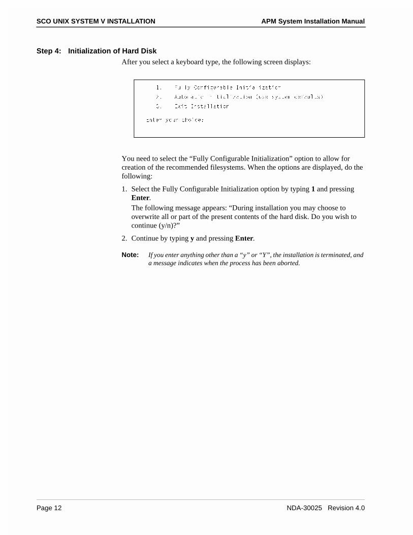
Step 4: Initialization of Hard DiskAfter you select a keyboard type, the following screen displays:
You need to select the “Fully Configurable Initialization” option to allow for creation of the recommended filesystems. When the options are displayed, do the following:
1. Select the Fully Configurable Initialization option by typing 1 and pressing Enter.The following message appears: “During installation you may choose to overwrite all or part of the present contents of the hard disk. Do you wish to continue (y/n)?”
2. Continue by typing y and pressing Enter.
Note: If you enter anything other than a “y” or “Y”, the installation is terminated, and a message indicates when the process has been aborted.
!� 6e\\i 3_^VYWebQR\U 9^YdYQ\YjQdY_^
"� 1ed_]QdYS 9^YdYQ\YjQdY_^ �ecU cicdU] TUVQe\dc�
#� 5hYd 9^cdQ\\QdY_^
5^dUb i_eb SX_YSU*
Page 12 NDA-30025 Revision 4.0

APM System Installation Manual SCO UNIX SYSTEM V INSTALLATION
Step 5: Display Current Disk ParametersAt this point, the formatting process should be completed and ready for verification of the drive’s parameters and bad track table. The following menu displays:
1. Type 1 and press Enter.The drive's parameters display. For a typical 1 Gibabyte hard drive, the parameter table should contain the following values:
Disk Parameters Values1. Cylinders 20472. Heads 163. Write Reduce 04. Write Precomp 05. Ecc 06. Control 87. Landing Zone 20488. Sectors/track 63
Note: The number of cylinders, sectors, and heads varies from disk to disk. These may need to be modified depending on the hard disk installed.
2. If the parameters are not correct, select option 2 (Modify current disk parameters) and press Enter.
3. Type the number associated with the incorrect value and press Enter.
4. At the prompt, enter the replacement value and press Enter.
5. Continue this process until all values are correct, and display the parameters by typing 1 and pressing Enter at the Hard Disk Drive 0 Configuration menu.
6. If the values are correct, exit the menu by typing q and pressing Enter.
8QbT 4Yc[ 4bYfU 3_^VYWebQdY_^
!� 4Yc`\Qi SebbU^d TYc[ `QbQ]UdUbc
"� =_TYVi SebbU^d TYc[ `QbQ]UdUbc
#� CU\USd TUVQe\d TYc[ `QbQ]UdUbc
5^dUb i_eb SX_YSU _b a d_ aeYd*
NDA-30025 Revision 4.0 Page 13

SCO UNIX SYSTEM V INSTALLATION APM System Installation Manual
Step 6: Elect to Use the Entire Disk for UNIXMost UAPs are used exclusively for the purpose of providing an OAI interface to the PBX and a host for the APM Platform. For that reason, the typical UAP installation requires only a single UNIX partition on the hard disk. If installation must include a DOS partition or multiple UNIX partitions, consult the SCO OS Installation Guide for guidance in creating them.
1. Select option 2 to use the entire disk for the UNIX operating system and press Enter.
2. If the operating system has previously been installed on the hard drive, the following prompt appears: “Warning! All data on your disk will be lost! Do you wish to continue! (y/n)?”Type y and press Enter.
3. At the prompt, press Enter.The menu redisplays.
4. Type q and press Enter. The following screen displays.
!� 4Yc`\Qi @QbdYdY_^ DQR\U
"� EcU 5^dYbU 4Yc[ V_b E>9H
#� EcU BUcd _V 4Yc[ V_b E>9H
$� 3bUQdU E>9H @QbdYdY_^
%� 1SdYfQdU @QbdYdY_^
&� 4U\UdU @QbdYdY_^
5^dUb i_eb SX_YSU _b a d_ aeYd*
!� @bY^d 3ebbU^d 2QT DbQS[ DQR\U
"� CSQ^ 4Yc[ �I_e ]Qi SX__cU BUQT�?^\i _b 4UcdbeSdYfU \QdUb�
#� 1TT 5^dbYUc d_ 3ebbU^d 2QT DbQS[ DQR\U Ri 3i\Y^TUb�8UQT >e]RUb
$� 1TT 5^dbYUc d_ 3ebbU^d 2QT DbQS[ DQR\U Ri CUSd_b >e]RUb
%� 4U\UdU 5^dbYUc 9^TYfYTeQ\\i Vb_] 3ebbU^d 2QT DbQS[ DQR\U
&� 4U\UdU 1\\ 5^dbYUc Vb_] 3ebbU^d 2QT DbQS[ DQR\U
5^dUb i_eb SX_YSU _b a d_ aeYd*
Page 14 NDA-30025 Revision 4.0

APM System Installation Manual SCO UNIX SYSTEM V INSTALLATION
Step 7: Perform a Destructive Disk Scan
1. As another level of verification, perform a destructive disk scan when the menu appears by typing a 2 and pressing Enter:The following menu displays:
2. Select a scan of the entire UNIX partition by typing 1 and pressing Enter.The following menu appears:
3. Type 2 and press Enter to select a thorough scan.The message “Do you want this to be a destructive scan? (y/n)” displays.
4. Type y and press Enter.The message “This will destroy the present contents of the region you are scanning. Do you wish to continue? (y/n)” displays.
5. Type y and press Enter.The message “Scanning in progress, type q to interrupt at any time” displays.The scanning operation takes some time, depending upon the size of the drive. The status of the operation is updated by the display of the track being scanned and the percentage of the disk already scanned.
6. After scanning is complete, the Bad Track menu is displayed again. To exit the menu, type q and press Enter.
Step 8: Accept Recommended Space Value for Bad TracksSCO provides recommended values for the space needed for bad tracks. When prompted for the desired value, simply accept the default value by pressing Enter.
The prompt is illustrated below:
Step 9: Accept Recommended Value for Swap SpaceAs in the previous step, a prompt requests the desired value for the size of the swap space to allocate. Once again simply accept the default value by pressing Enter at the given prompt and continue on to the next step.
Step 10: Create a Separate /u FilesystemAfter you accept the recommended value for swap space, the “Do you want a separate /u filesystem? (y/n)” prompt displays. Type n and press Enter.
!� CSQ^ U^dYbU E>9H `QbdYdY_^
"� CSQ^ Q c`USYVYUT bQ^WU _V dbQS[c
#� CSQ^ Q c`USYVYUT VY\UcicdU]
5^dUb Q^ _`dY_^ _b a d_ aeYd*
!� AeYS[ cSQ^ �Q``b_hY]QdU\i ' ]UWQRidUc�]Y^�
"� DX_b_eWX cSQ^ �Q``b_hY]QdU\i ! ]UWQRidU�]Y^�
5^dUb Q^ _`dY_^ _b ´aµ d_ aeYd*
5^dUb dXU ^e]RUb _V RQT dbQS[c d_ Q\\_SQdU c`QSU V_b
�_b `bUcc ,BUdeb^. d_ ecU dXU bUS_]]U^TUT fQ\eU _V !%�*
NDA-30025 Revision 4.0 Page 15
SCO UNIX SYSTEM V INSTALLATION APM System Installation Manual
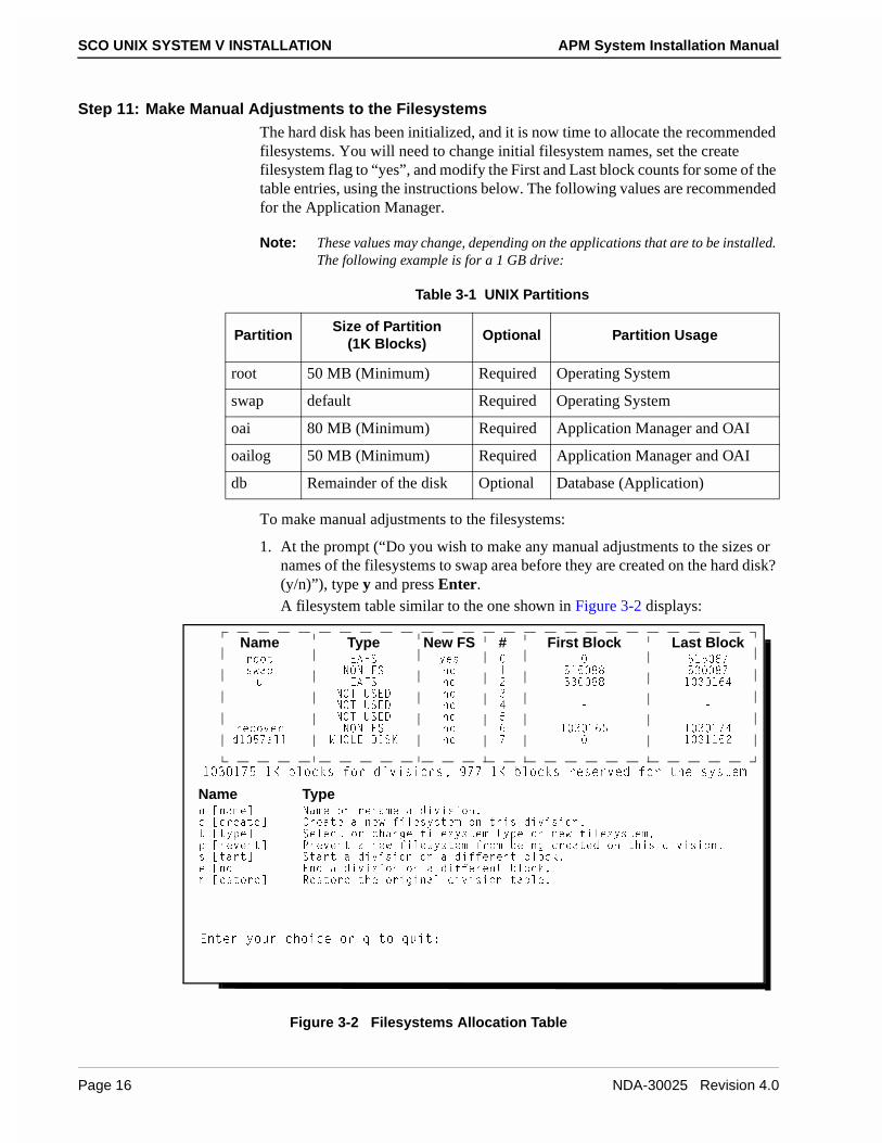
Step 11: Make Manual Adjustments to the FilesystemsThe hard disk has been initialized, and it is now time to allocate the recommended filesystems. You will need to change initial filesystem names, set the create filesystem flag to “yes”, and modify the First and Last block counts for some of the table entries, using the instructions below. The following values are recommended for the Application Manager.
Note: These values may change, depending on the applications that are to be installed. The following example is for a 1 GB drive:
To make manual adjustments to the filesystems:
1. At the prompt (“Do you wish to make any manual adjustments to the sizes or names of the filesystems to swap area before they are created on the hard disk? (y/n)”), type y and press Enter. A filesystem table similar to the one shown in Figure 3-2 displays:
Figure 3-2 Filesystems Allocation Table
Table 3-1 UNIX Partitions
PartitionSize of Partition
(1K Blocks)Optional Partition Usage
root 50 MB (Minimum) Required Operating System
swap default Required Operating System
oai 80 MB (Minimum) Required Application Manager and OAI
oailog 50 MB (Minimum) Required Application Manager and OAI
db Remainder of the disk Optional Database (Application)
Name Type New FS # First Block Last Blockb__d 516C iUc %!% ('
cgQ` >?> 6C ^_ ! %!% (( %# ('
e 516C ^_ " %# (( ! # !&$
>?D EC54 ^_ # � �
>?D EC54 ^_ $ � �
>?D EC54 ^_ % � �
bUS_fUb >?> 6C ^_ & ! # !&% ! # !'$
T! %'Q\\ G8?<5 49C; ^_ ' ! #!!%"
Name Type^ K^Q]UM >Q]U _b bU^Q]U Q TYfYcY_^�
S KSbUQdUM 3bUQdU Q ^Ug VY\UcicdU] _^ dXYc TYfYcY_^�
d Kdi`UM CU\USd _b SXQ^WU VY\UcicdU] di`U _^ ^Ug VY\UcicdU]�
` KbUfU^dM @bUfU^d Q ^Ug VY\UcicdU] Vb_] RUY^W SbUQdUT _^ dXYc TYfYcY_^�
c KdQbdM CdQbd Q TYfYcY_^ _^ Q TYVVUbU^d R\_S[�
U K^TM 5^T Q TYfYcY_^ _^ Q TYVVUbU^d R\_S[�
b KUcd_bUM BUcd_bU dXU _bYWY^Q\ TYfYcY_^ dQR\U�
5^dUb i_eb SX_YSU _b a d_ aeYd*
! # !'% !; R\_S[c V_b TYfYcY_^c� )'' !; R\_S[c bUcUbfUT V_b dXU cicdU]
Page 16 NDA-30025 Revision 4.0
APM System Installation Manual SCO UNIX SYSTEM V INSTALLATION
2. To create or rename a division, type n and press Enter.
3. Select a division to rename (0-7) and press Enter. (The division numbers are located in the # column of the allocation table, as illustrated in Figure 3-2.)
4. At the “What do you want to call it?” prompt, type the name of the division and press Enter.Repeat this process (steps 1 through 4) for each of the following division names:
• root
• swap
• oai
• oailog
• db
5. Now the sizes of each of the partitions need to be configured. These will vary depending on the size of the hard disk and the requirements of the applications and customer.
• To start a division on a different block, type s and press Enter. Type the number of the division for which you want to change the starting block and press Enter. (The division numbers are located in the # column of the allocation table, as illustrated in Figure 3-2.) Type the new starting value and press Enter.
• To end a division on a different block, type e and press Enter. Type the number of the division for which you want to change the ending block and press Enter. (The division numbers are located in the # column of the allocation table, as illustrated in Figure 3-2.) Type the new ending value and press Enter.
Repeat this process for each of the divisions. The following table shows typical starting and ending values for a 1 Gigabyte hard drive:
6. The new filesystem flag should be turned to yes for the root, oai, and oailog divisions. (In other words, yes should appear in the New FS column of the allocation table which is illustrated in Figure 3-2.) If one of these flags is no, type c and press Enter at the prompt. Type the number of the division for which you need to create a new filesystem and press Enter.Continue this process until you have created a new filesystem for the root, oai, and oailog divisions.
7. When you have completed the adjustments to the filesystems, type q and press Enter.
Division First Block Last Block
root 0 99999
swap 100000 163999
oai 164000 263999
oailog 264000 363999
db 364000 863999
NDA-30025 Revision 4.0 Page 17

SCO UNIX SYSTEM V INSTALLATION APM System Installation Manual
Step 12: Provide Remainder of Installation MediaAfter you complete the adjustments to the filesystems, the following menu appears:
To install the remainder of the installation media:
1. Type i and press Enter.The Product Medium Selection menu displays, as illustrated below:
2. Type the number that corresponds to the type of media you are using to install the product and press Enter. If you are using floppy disks, type 1 and press Enter.The following prompt displays:
3. Insert the N1 disk and press Enter.
4. Follow the prompts that are displayed on your screen, inserting the appropriate diskettes and pressing Enter.
YK^cdQ\\M 9^cdQ\\ dXU TYfYcY_^ cUd�e` cX_g^
bKUdeb^M BUdeb^ d_ dXU `bUfY_ec ]U^e
C3? cicdU]c c_VdgQbU `b_fYTUc dXbUU ]UTYQ V_b Y^cdQ\\Y^W dXU `b_TeSd�
1d dXYc `_Y^d� i_e SQ^ cU\USd dXU Y^cdQ\\QdY_^ ]UTYe] Q^T S_^VYWebU
dXU TbYfUb `QbQ]UdUbc V_b dXU Y^cdQ\\QdY_^ TUfYSU�
=UTYe] CU\USdY_^*
!� 6\_``i 4Yc[UddU
"� 3QbdbYTWU DQ`U
#� 3_]`QSd 4YcS �34�B?=�
5^dUb i_eb SX_YSU _b a d_ aeYd*
9^cUbd >! �2__d� V\_``i Y^ dXU TbYfU
Q^T `bUcc ,BUdeb^. _b U^dUb a d_ aeYd*
Page 18 NDA-30025 Revision 4.0

APM System Installation Manual SCO UNIX SYSTEM V INSTALLATION
Step 13: Enter Serial Number and Activation KeyA prompt requests the unique serial number and activation key. These values are supplied on a card with the original SCO manufacturer’s documentation. (This card should be stored in a secure location after the operating system installation is completed.) At the start of this sequence, enter the serial number at the prompt and press Enter, as shown:
Enter your serial number or enter q to quit: xxxxxxxxx <Enter>
Then enter the given activation key as follows:
Enter your activation key or enter q to quit: xxxxxxx <Enter>
Step 14: Enter Time Zone and Daylight Savings Time InformationA series of prompts now makes it possible to specify the correct time zone and daylight savings time information. Enter the appropriate information, and continue with the next step.
Step 15: Install Extended Operating System UtilitiesAfter you have entered the time zone information, the following menu appears which allows you to install extended utilities or applications:
1. Type 1 and press Enter.The following menu displays:
!� 9^cdQ\\ QTTYdY_^Q\ c_VdgQbU
"� 3_^dY^eU Y^cdQ\\QdY_^
5^dUb Q^ _`dY_^ _b ´aµ d_ aeYd*
3ecd_]
C3? E>9H CicdU] F ?`UbQdY^W CicdU]
9^cdQ\\ BU]_fU <Ycd AeYd
@b_TeSdc 3ebbU^d\i 9^cdQ\\UT
/ GUT^UcTQi ?Sd_RUb )� !))& #*#)
NDA-30025 Revision 4.0 Page 19

SCO UNIX SYSTEM V INSTALLATION APM System Installation Manual
2. Select the Install option using the arrow keys and press Enter. (Install is highlighted when it is selected.)The following menu displays:
3. Select SCO UNIX System V Operating System using the arrow keys and press Enter.The following menu appears:
4. Select Entire Product using the arrow keys and press Enter.
5. At the prompt, insert the SCO UNIX Extended Utility Floppy Volume X1 diskette and press Enter.
6. Continue this process, inserting the appropriate diskettes when prompted.After you have loaded all of the software, the SCO UNIX System V Operating System Init Script runs, and the following prompt displays:
CU\USd Q `b_TeSd d_ Y^cdQ\\ Q^T `bUcc ,BUdeb^.
9^cdQ\\
/ GUT^UcTQi ?Sd_RUb )� !))& #*#)
@bUcc ,5C3. d_ SQ^SU\� ]_fU]U^d [Uic QbU QSdYfU
9^cdQ\\
CU\USd Q `b_TeSd* K M
3X__cU Q^ _`dY_^* 5^dYbU @b_TeSd @QS[QWUc 6Y\Uc
1 >Ug @b_TeSd
�C3? E>9H CicdU] F ?`UbQdY^W CicdU]
9^cdQ\\
/ GUT^UcTQi ?Sd_RUb )� !))& #*#)
9^cdQ\\ dXU S_]`\UdU TYcdbYRedY_^
9^cdQ\\
3X__cU Q^ _`dY_^* 5^dYbU @b_TeSd @QS[QWUc 6Y\Uc
I_eb cicdU] ^Q]U Yc cUd d_ cS_cicf�
4_ i_e gYcX dXU ]QY\ cicdU] d_ ecU Q TYVVUbU^d ^Q]U/ �i�^�
Page 20 NDA-30025 Revision 4.0

APM System Installation Manual SCO UNIX SYSTEM V INSTALLATION
7. Type y and press Enter.
8. Type a name unique to your site and press Enter.
9. At the prompt, press Enter to continue.The following menu displays:
10.Press Enter.The Custom menu redisplays.
11.Using the arrow keys, select Quit and press Enter.
12.Press Enter again while Yes is highlighted to exit.
Step 16: Select Relaxed System SecurityIt is now necessary to decide on the desired level of security for your UNIX system. After you exit the Custom menu, the following screen displays:
1. Select Traditional UNIX security by typing 3 and pressing Enter.
2. Continue with the installation described in the next section.
/ GUT^UcTQi ?Sd_RUb )� !))& #*#)
@bUcc Q^i [Ui d_ S_^dY^eU
DbecdUT CicdU] 3_^VYWebQdY_^
DXU cicdU] Yc TUcYW^UT d_ ]UUd dXU bUaeYbU]U^dc V_b dXU 3" \UfU\ _V dbecd
TUcSbYRY^W dXU `b_dUSdY_^ WYfU^ d_ `bUfU^d e^QedX_bYjUT QSSUcc d_ Q cicdU]
Q^T Ydc TQdQ� <UfU\c ! Q^T " RU\_g QbU ceYdQR\U V_b 3" cicdU]c�
I_e ]Qi bUS_^VYWebU i_eb cicdU] cUSebYdi d_ ceYd i_eb _g^ bUaeYbU]U^dc�
6_eb \UfU\c _V `bUS_^VYWebUT cUSebYdi TUVQe\dc QbU QfQY\QR\U*
!� 8YWX cUSebYdi � bUS_]]U^TUT V_b cicdU]c S_^dQY^Y^W S_^VYTU^dYQ\
Y^V_b]QdY_^ Q^T QSSUccUT Ri ]Q^i ecUbc�
"� 9]`b_fUT cUSebYdi � bUS_]]U^TUT V_b cicdU]c QSSUccUT Ri Wb_e`c _V
ecUbc gX_ ]Qi cXQbU Y^V_b]QdY_^�
#� DbQTYdY_^Q\ E>9H cUSebYdi � `b_fYTUT V_b S_]`QdYRY\Ydi gYdX _dXUb
UhYcdY^W E>9H cicdU]c�
$� <_g cUSebYdi � bUS_]]U^TUT _^\i V_b cicdU]c ^_d `eR\YS\i
QSSUccYR\U Q^T ecUT Ri Q c]Q\\ ^e]RUb _V S__`UbQdY^W ecUbc�
5^dUb i_eb SX_YSU*
NDA-30025 Revision 4.0 Page 21

SCO UNIX SYSTEM V INSTALLATION APM System Installation Manual
Step 17: Continue InstallationAfter selecting a security type, the following menu displays:
1. Type 2 and press Enter.
2. Continue with the root password assignment described in the next section.
Step 18: Enter Root PasswordIn this step, the system prompts you to enter a password with the following menu:
1. Type 1 and press Enter.
2. At the prompt, type a password and press Enter.
3. Re-enter the password at the prompt and press Enter.
Note: Make sure to store the password in a safe place so that you will be able to login.
Step 19: Shutdown and RebootThis concludes the required SCO UNIX installation. After the “Power Off or Reboot” prompt is displayed, reboot the system from the hard disk by removing the floppy from the disk drive and pressing any key.
The screen will clear and display the “Boot:” prompt.
!� Be^ CicdU] 1T]Y^YcdbQdY_^ CXU\\
"� 3_^dY^eU Y^cdQ\\QdY_^
5^dUb Q^ _`dY_^ _b a d_ aeYd*
!� @YS[ i_eb _g^ `Qccg_bT
"� @b_^_e^SUQR\U `Qccg_bT gY\\ RU WU^UbQdUT V_b i_e
5^dUb SX_YSU �TUVQe\d Yc !�*
Page 22 NDA-30025 Revision 4.0

APM System Installation Manual SCO UNIX SYSTEM V INSTALLATION
Adding Drivers to UNIX
If any specific boards or drivers are required by the system or application, custom or installpkg are used to install the new drivers.
1. From the “Boot:” prompt, press Enter.
2. Type your user password and press Enter.The “#” prompt appears.
Parallel I/O Device The parallel I/O device is used by the printer on the OAI system. To install the parallel port issue the following command:
1. At the “#” prompt, type mkdev parallel and press Enter.The following screen appears:
2. Type 1 and press Enter.The following screen appears:
3. Type 1 and press Enter.
4. At the “Should this port use interrupt (default [7])” prompt, press Enter.The message “Do you wish to create a new kernel now? (y/n)” appears.
5. Type n and press Enter.
4_ i_e gYcX d_*
!� 1TT Q `QbQ\\U\ `_bd
"� BU]_fU Q `QbQ\\U\ `_bd
#� CX_g S_^VYWebQdY_^
$� 8U\`
CU\USd Q^ _`dY_^ _b U^dUb a d_ aeYd*
@\UQcU cU\USd dXU 9�? QTTbUcc V_b dXU QTQ`dUb*
!� CUbYQ\�@QbQ\\U\ QTQ`dUb �! * QTTbUcc - #'(�#'V
"� @QbQ\\U\�=_^_SXb_]U QTQ`dUb * QTTbUcc - #RS�#RU
#� CUbYQ\�@QbQ\\U\ QTQ`dUb �" * QTTbUcc - "'(�"'Q
$� ?dXUb S_^VYWebQdY_^
CU\USd Q^ _`dY_^ _b U^dUb a d_ aeYd*
NDA-30025 Revision 4.0 Page 23

SCO UNIX SYSTEM V INSTALLATION APM System Installation Manual
Second Serial I/O Device
1. At the “#” prompt, type mkdev serial and press Enter.The following screen appears:
2. Type i and press Enter.The following screen appears:
3. Select the number corresponding to the port card to be added and press Enter.
4. Select the COM port for the device and press Enter.
5. Type the number that corresponds to the card you are using and press Enter. (Quadram and IBM-COM2 cards are supported.)
6. Type the baud rate to be used on the modem devices and press Enter.
7. Select an entry that corresponds to the baud rate and press Enter.
8. At the “Do you wish to create a new kernel now? (y/n)” prompt, type n and press Enter.
DXU V_\\_gY^W SQbTc QbU SebbU^d\i S_^VYWebUT*
!� 92=�3?=! ! `_bd SQbT Y�_ QTTbUcc - #V(� Y^dUbbe`d - 3?=!
Y�^cdQ\\ Q ^Ug cUbYQ\ R_QbT
b�U]_fU Q^ UhYcdY^W R_QbT
a�eYd
@\UQcU U^dUb i_eb SX_YSU �Y�b�a� .
I_e g_e\T \Y[U d_ Y^cdQ\\ Q*
!� ! `_bd SQbT
"� " `_bd SQbT
#� $ `_bd SQbT
$� % `_bd SQbT
%� ( `_bd SQbT
&� !& `_bd SQbT
5^dUb i_eb SX_YSU _b a d_ aeYd*
Page 24 NDA-30025 Revision 4.0

APM System Installation Manual SCO UNIX SYSTEM V INSTALLATION
SCSI Adapter Device
Installing a SCSI adapter device may require custom or installpkg.
Note: This is an example of the 7800 SCSI adapter using the installpkg command.
1. At the “#” prompt, type installpkg and press Enter.
2. Insert the SCSI Device Driver Floppy Disk (7800 Family Manager for SCO UNIX) and press Enter.If the program installation requires more than one floppy disk, be sure to insert the disks in the proper order, starting with disk number 1.
3. A prompt displays the packages that are on the disk. Type the name of the package you want to install (e.g. alad) and press Enter.
SCSI Tape Device After installing the SCSI adapter, you can install a SCSI tape drive. To install any tape devices use the mkdev tape command.
Note: This example will install a SCSI tape device.
1. At the “#” prompt, type mkdev tape and press Enter.The Tape Drive Configuration Program menu appears, as illustrated below:
2. Type 1 and press Enter.The Tape Drive Installation Menu appears, as illustrated below:
DQ`U 4bYfU 3_^VYWebQdY_^ @b_WbQ]
!� 9^cdQ\\ Q DQ`U 4bYfU
"� BU]_fU Q DQ`U 4bYfU
#� 3XQ^WU TUVQe\d DQ`U 4bYfU
CU\USd Q^ _`dY_^ _b U^dUb a d_ aeYd*
DQ`U 4bYfU 9^cdQ\\QdY_^ =U^e
!� 9^cdQ\\ 3QbdbYTWU DQ`U 4bYfU
"� 9^cdQ\\ =Y^Y�3QbdbYTWU DQ`U 4bYfU
#� 9^cdQ\\ AYS�$ _b AYS�( DQ`U 4bYfU
$� 9^cdQ\\ C3C9 DQ`U 4bYfU
CU\USd Q^ _`dY_^ _b U^dUb a d_ bUdeb^ d_ dXU ]QY^ ]U^e*
NDA-30025 Revision 4.0 Page 25

SCO UNIX SYSTEM V INSTALLATION APM System Installation Manual
3. Select the tape drive you want to install and press Enter. (In this example, type 4 and press Enter.)The following menu appears:
4. Select the appropriate drive (e.g., 1), and press Enter.
5. At the “Do you wish to configure the SCSI Cartridge Tape Drive now? (y/n)” prompt, type y and press Enter.
6. Enter the prefix of the SCSI host adapter by typing alad and pressing Enter.
7. At the “Which ‘alad’ SCSI hot adapter supports this device?” prompt, type 0 and press Enter.
8. Enter the Target ID for the device by typing 2 or pressing Enter.
9. Enter the LUN of the device by typing 0 and pressing Enter.
10.At the “Update SCSI configuration? (y/n)” prompt, type y and press Enter.
11.At the prompt, press Enter to continue.
12.To leave the current string, type q and press Enter.The Tape Drive Configuration Program menu displays.
13.Type q and press Enter.
14.At the “Do you wish to create a new kernel now? (y/n)” prompt, type n and press Enter.
C3C9 DQ`U 4bYfU 9^cdQ\\QdY_^ =U^e
!� 9^cdQ\\ C3C9 3QbdbYTWU DQ`U 4bYfU
"� 9^cdQ\\ C3C9 5hQRidU DQ`U 4bYfU
#� 9^cdQ\\ C3C9 )�DbQS[ DQ`U 4bYfU
$� 9^cdQ\\ C3C9 41D 4bYfU
%� 9^cdQ\\ 3_]`Qa C3C9 DQ`U 4bYfU
CU\USd Q^ _`dY_^ _b U^dUb a d_ bUdeb^ d_ dXU ]QY^ ]U^e*
Page 26 NDA-30025 Revision 4.0
APM System Installation Manual SCO UNIX SYSTEM V INSTALLATION
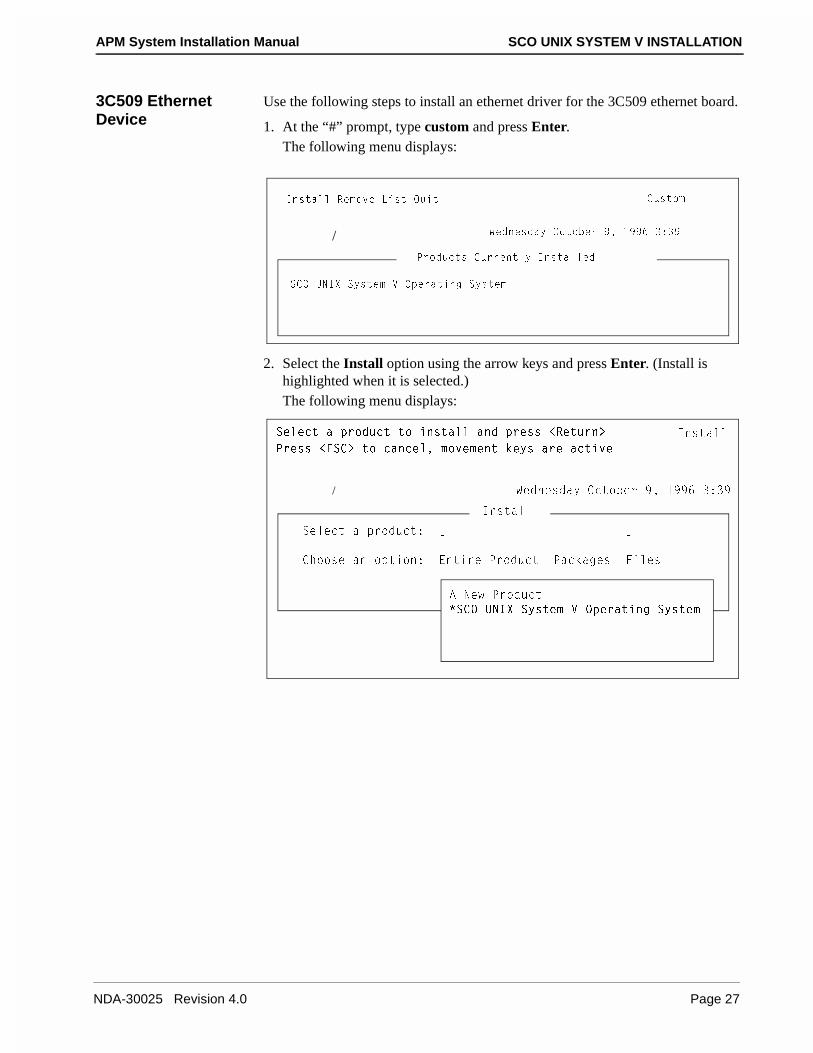
3C509 Ethernet Device
Use the following steps to install an ethernet driver for the 3C509 ethernet board.
1. At the “#” prompt, type custom and press Enter.The following menu displays:
2. Select the Install option using the arrow keys and press Enter. (Install is highlighted when it is selected.)The following menu displays:
3ecd_]
C3? E>9H CicdU] F ?`UbQdY^W CicdU]
9^cdQ\\ BU]_fU <Ycd AeYd
@b_TeSdc 3ebbU^d\i 9^cdQ\\UT
/ GUT^UcTQi ?Sd_RUb )� !))& #*#)
CU\USd Q `b_TeSd d_ Y^cdQ\\ Q^T `bUcc ,BUdeb^.
9^cdQ\\
/ GUT^UcTQi ?Sd_RUb )� !))& #*#)
@bUcc ,5C3. d_ SQ^SU\� ]_fU]U^d [Uic QbU QSdYfU
9^cdQ\\
CU\USd Q `b_TeSd* K M
3X__cU Q^ _`dY_^* 5^dYbU @b_TeSd @QS[QWUc 6Y\Uc
1 >Ug @b_TeSd
�C3? E>9H CicdU] F ?`UbQdY^W CicdU]
NDA-30025 Revision 4.0 Page 27

SCO UNIX SYSTEM V INSTALLATION APM System Installation Manual
3. Select A New Product using the arrow keys and press Enter.The following menu appears:
4. Select Entire Product using the arrow keys and press Enter.
5. At the prompt, insert the 3C509 Ethernet III Driver Floppy diskette and press Enter.
6. Press Enter at the prompt to continue the installation.
7. After the installation is complete, press Enter to continue.
9^cdQ\\
/ GUT^UcTQi ?Sd_RUb )� !))& #*#)
9^cdQ\\ dXU S_]`\UdU TYcdbYRedY_^
9^cdQ\\
3X__cU Q^ _`dY_^* 5^dYbU @b_TeSd @QS[QWUc 6Y\Uc
Page 28 NDA-30025 Revision 4.0

APM System Installation Manual SCO UNIX SYSTEM V INSTALLATION
TCP/IP Runtime System
Use the following steps to install the TCP/IP Runtime System.
1. At the “#” prompt, type custom and press Enter.The following menu displays:
2. Select the Install option using the arrow keys and press Enter. (Install is highlighted when it is selected.)The following menu displays:
3ecd_]
C3? E>9H CicdU] F ?`UbQdY^W CicdU]
9^cdQ\\ BU]_fU <Ycd AeYd
@b_TeSdc 3ebbU^d\i 9^cdQ\\UT
/ GUT^UcTQi ?Sd_RUb )� !))& #*#)
CU\USd Q `b_TeSd d_ Y^cdQ\\ Q^T `bUcc ,BUdeb^.
9^cdQ\\
/ GUT^UcTQi ?Sd_RUb )� !))& #*#)
@bUcc ,5C3. d_ SQ^SU\� ]_fU]U^d [Uic QbU QSdYfU
9^cdQ\\
CU\USd Q `b_TeSd* K M
3X__cU Q^ _`dY_^* 5^dYbU @b_TeSd @QS[QWUc 6Y\Uc
1 >Ug @b_TeSd
�C3? E>9H CicdU] F ?`UbQdY^W CicdU]
NDA-30025 Revision 4.0 Page 29

SCO UNIX SYSTEM V INSTALLATION APM System Installation Manual
3. Select A New Product using the arrow keys and press Enter.The following menu appears:
4. Select Entire Product using the arrow keys and press Enter.
5. At the prompt, insert the SCO TCP/IP Runtime Floppy Disk Volume 1 diskette and press Enter.
6. Press Enter at the prompt to continue the installation.
7. Continue this process, inserting the appropriate diskettes when prompted.
8. When prompted, use the serial number and activation key included with the SCO TCP/IP Runtime System distribution to enter the serial number and activation key. The serial number can be found on the SCO Product Activation Key Card in the Read This First booklet.
9. At the “Enter the system node name” prompt, press Enter.
10.Type the domain name for the node and press Enter.The following screen appears:
11.Press Enter.
12.At the “Do you want to relink the kernel now?” prompt, type n and press Enter.
13.At the prompt, press Enter to continue.
Note: Make sure that you remove the SCO TCP/IP Runtime Disk Volume 3 from the floppy disk drive.
9^cdQ\\
/ GUT^UcTQi ?Sd_RUb )� !))& #*#)
9^cdQ\\ dXU S_]`\UdU TYcdbYRedY_^
9^cdQ\\
3X__cU Q^ _`dY_^* 5^dYbU @b_TeSd @QS[QWUc 6Y\Uc
"%& D3@ S_^^USdY_^c SebbU^d\i S_^VYWebUT� T_ i_e gQ^d d_*
!� 1TT D3@ 3_^^USdY_^c
"� BU]_fU D3@ 3_^^USdY_^c
CU\USd Q^ _`dY_^ _b U^dUb a d_ aeYd KaM*
Page 30 NDA-30025 Revision 4.0

APM System Installation Manual SCO UNIX SYSTEM V INSTALLATION
LLI Drivers Use the following steps to install the LLI Drivers which are needed to configure network drivers into the kernel.
1. At the “#” prompt, type custom and press Enter.The following menu displays:
2. Select the Install option using the arrow keys and press Enter. (Install is highlighted when it is selected.)The following menu displays:
3ecd_]
C3? E>9H CicdU] F ?`UbQdY^W CicdU]
9^cdQ\\ BU]_fU <Ycd AeYd
@b_TeSdc 3ebbU^d\i 9^cdQ\\UT
/ GUT^UcTQi ?Sd_RUb )� !))& #*#)
CU\USd Q `b_TeSd d_ Y^cdQ\\ Q^T `bUcc ,BUdeb^.
9^cdQ\\
/ GUT^UcTQi ?Sd_RUb )� !))& #*#)
@bUcc ,5C3. d_ SQ^SU\� ]_fU]U^d [Uic QbU QSdYfU
9^cdQ\\
CU\USd Q `b_TeSd* K M
3X__cU Q^ _`dY_^* 5^dYbU @b_TeSd @QS[QWUc 6Y\Uc
1 >Ug @b_TeSd
�C3? E>9H CicdU] F ?`UbQdY^W CicdU]
�C3? D3@�9@ Be^dY]U CicdU]
NDA-30025 Revision 4.0 Page 31

SCO UNIX SYSTEM V INSTALLATION APM System Installation Manual
3. Select A New Product using the arrow keys and press Enter.The following menu appears:
4. Select Entire Product using the arrow keys and press Enter.
5. At the prompt, insert the SCO LLI Floppy Disk Volume 1 diskette and press Enter.
6. Press Enter at the prompt to continue the installation.
7. When the installation is complete, press Enter to continue.
8. Using the arrow keys, select Quit and press Enter.
9. Press Enter again while Yes is highlighted to exit.
10.Remove the SCO LLI Floppy Disk Volume 1 from the floppy disk drive.
9^cdQ\\
/ GUT^UcTQi ?Sd_RUb )� !))& #*#)
9^cdQ\\ dXU S_]`\UdU TYcdbYRedY_^
9^cdQ\\
3X__cU Q^ _`dY_^* 5^dYbU @b_TeSd @QS[QWUc 6Y\Uc
Page 32 NDA-30025 Revision 4.0

APM System Installation Manual SCO UNIX SYSTEM V INSTALLATION
Network Configuration
At this point, you need to configure the TCP/IP.
1. At the “#” prompt, type netconfig and press Enter.The following screen displays:
2. Type 1 and press Enter.
3. Select the top level of the chain to add and press Enter.
4. Select the next level of chain to add and press Enter.
5. Confirm your selection by typing y and pressing Enter.
Note: The setup procedure for the 3Com EtherLink III adapter is dependent on whether it is an ISA bus adapter (3C509), an EISA bus adapter (3C579), an MCA bus adapter (3C529), or a PCMCIA bus adapter (3C589). You must know which EtherLink III adapter type you have in order to configure the adapter correctly.
6. Type the appropriate information for the adapter type you are using at the prompts, pressing Enter after each entry.
Note: For each ISA bus adapter, there are three parameters which you may need to supply: the Interrupt Request Level, the I/O Base Address, and the Transceiver Type. However, because the adapter can be configured automatically, you can choose not to specify configuration parameters and let them be chosen for you. An available Interrupt Request Level and I/O Base Address will be selected, and the driver will automatically select the transceiver based on which connector the network is attached to. If you wish to automatically configure the adapter, answer yes at the next prompt.
7. After you verify the Interface Address, Netmask, and Broadcast Address information, the following screen appears:
8. Type 1 and press Enter.
1fQY\QR\U _`dY_^c*
!� 1TT Q SXQY^
"� BU]_fU Q SXQY^
#� BUS_^VYWebU Q^ U\U]U^d Y^ Q SXQY^
a� AeYd
CU\USd _`dY_^*
@cUeT_ ddic QbU SebbU^d\i S_^VYWebUT� T_ i_e gQ^d d_*
!� 1TT @cUeT_ ddic
"� BU]_fU @cUeT_ ddic
CU\USd Q^ _`dY_^ _b U^dUb a d_ aeYd KaM*
NDA-30025 Revision 4.0 Page 33

SCO UNIX SYSTEM V INSTALLATION APM System Installation Manual
9. At the “How many additional pseduo ttys you want to be created” prompt, press Enter.
10.To exit the TCP Connections menu, type q and press Enter.
11.To exit the chain menu, type q and press Enter.
12.The system prompts you to relink the kernel. If there are no other drivers to be installed, type y and Enter to relink the kernel now. If there are other drivers to be installed (i.e. SunRiver Driver), type n and press Enter, and install the drivers as needed. After all of the drivers have been installed, relink the kernel and then reboot by typing shutdown -g0 -y -i0 and press Enter.
Page 34 NDA-30025 Revision 4.0
APM System Installation Manual SCO UNIX SYSTEM V INSTALLATION
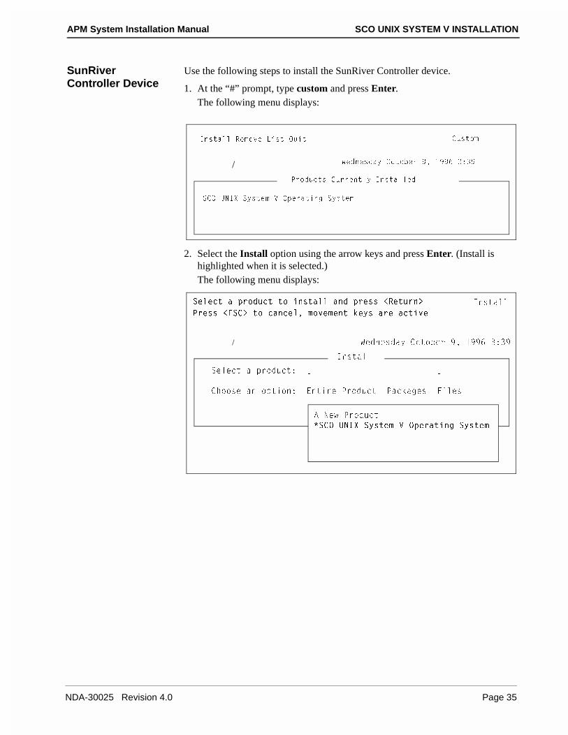
SunRiver Controller Device
Use the following steps to install the SunRiver Controller device.
1. At the “#” prompt, type custom and press Enter.The following menu displays:
2. Select the Install option using the arrow keys and press Enter. (Install is highlighted when it is selected.)The following menu displays:
3ecd_]
C3? E>9H CicdU] F ?`UbQdY^W CicdU]
9^cdQ\\ BU]_fU <Ycd AeYd
@b_TeSdc 3ebbU^d\i 9^cdQ\\UT
/ GUT^UcTQi ?Sd_RUb )� !))& #*#)
CU\USd Q `b_TeSd d_ Y^cdQ\\ Q^T `bUcc ,BUdeb^.
9^cdQ\\
/ GUT^UcTQi ?Sd_RUb )� !))& #*#)
@bUcc ,5C3. d_ SQ^SU\� ]_fU]U^d [Uic QbU QSdYfU
9^cdQ\\
CU\USd Q `b_TeSd* K M
3X__cU Q^ _`dY_^* 5^dYbU @b_TeSd @QS[QWUc 6Y\Uc
1 >Ug @b_TeSd
�C3? E>9H CicdU] F ?`UbQdY^W CicdU]
NDA-30025 Revision 4.0 Page 35
SCO UNIX SYSTEM V INSTALLATION APM System Installation Manual
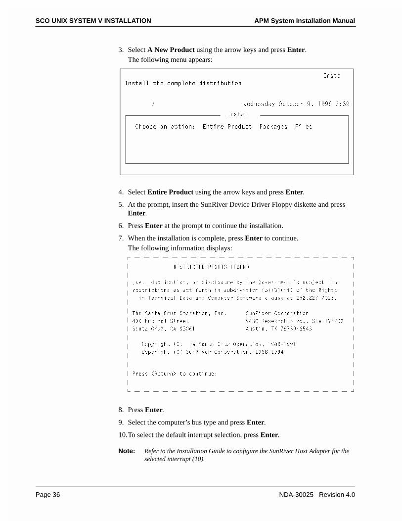
3. Select A New Product using the arrow keys and press Enter.The following menu appears:
4. Select Entire Product using the arrow keys and press Enter.
5. At the prompt, insert the SunRiver Device Driver Floppy diskette and press Enter.
6. Press Enter at the prompt to continue the installation.
7. When the installation is complete, press Enter to continue.The following information displays:
8. Press Enter.
9. Select the computer’s bus type and press Enter.
10.To select the default interrupt selection, press Enter.
Note: Refer to the Installation Guide to configure the SunRiver Host Adapter for the selected interrupt (10).
9^cdQ\\
/ GUT^UcTQi ?Sd_RUb )� !))& #*#)
9^cdQ\\ dXU S_]`\UdU TYcdbYRedY_^
9^cdQ\\
3X__cU Q^ _`dY_^* 5^dYbU @b_TeSd @QS[QWUc 6Y\Uc
B5CDB93D54 B978DC <575>4
EcU� Te`\YSQdY_^� _b TYcS\_cebU Ri dXU 7_fUb^]U^d Yc ceRZUSd d_
bUcdbYSdY_^c Qc cUd V_bdX Y^ ceRTYfYcY_^ �R��#��YY� _V dXU BYWXdc
Y^ DUSX^YSQ\ 4QdQ Q^T 3_]`edUb C_VdgQbU S\QecU Qd "%"�""'�' !#�
DXU CQ^dQ 3bej ?`UbQdY_^� 9^S� Ce^BYfUb 3_b`_bQdY_^
$ 5^SY^Q\ CdbUUd )$# BUcUQbSX 2\fT�� CdU 9F�"
CQ^dQ 3bej� 31 )% &! 1ecdY^� DH '('%)�&%$#
3_`ibYWXd �3� DXU CQ^dQ 3bej ?`UbQdY_^� !)((�!))!
3_`ibYWXd �3� Ce^BYfUb 3_b`_bQdY_^� !)((�!))$
@bUcc ,BUdeb^. d_ S_^dY^eU*
Page 36 NDA-30025 Revision 4.0

APM System Installation Manual SCO UNIX SYSTEM V INSTALLATION
11.Enter the number of multiscreens per station and press Enter.
12.At the “Do you wish to relink the kernel now?” prompt, type y and press Enter.
13.When the driver installation completes, press Enter to continue.
14.To exit Custom, press the right arrow key until Quit is selected and press Enter.
15.Press Enter again while Yes is highlighted to exit.
16.Remove the SunRiver Terminal Driver floppy disk.
17.At the “#” prompt, type shutdown -g0 -y -i0 and press Enter.The system shuts down.
NDA-30025 Revision 4.0 Page 37

SCO UNIX SYSTEM V INSTALLATION APM System Installation Manual
This Page Left Blank.
Page 38 NDA-30025 Revision 4.0
APM System Installation Manual APPLICATION MANAGER INSTALLATION
Chapter 4 APPLICATION MANAGER INSTALLATION
Use the information provided in this chapter to install the Application Manager (APM) on your system.
1. To begin the installation, the Application Manager must be installed from single user mode. To enter single user mode, you can reboot the system or use the shutdown -g0 -y -is command. To use the shutdown -g0 -y -is command, use the following steps:
(a) At the login prompt, type root and press Enter.
(b) At the password prompt, type your password and press Enter.The “#” prompt displays.
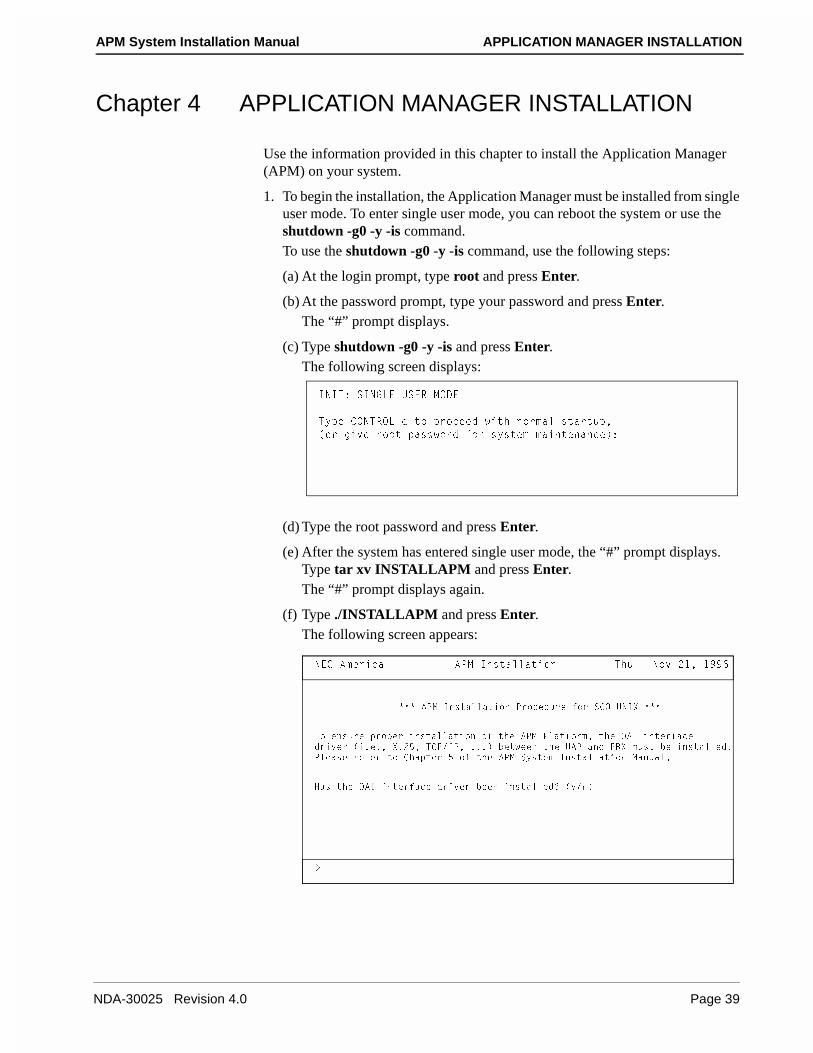
(c) Type shutdown -g0 -y -is and press Enter.The following screen displays:
(d) Type the root password and press Enter.
(e) After the system has entered single user mode, the “#” prompt displays. Type tar xv INSTALLAPM and press Enter.The “#” prompt displays again.
(f) Type ./INSTALLAPM and press Enter.The following screen appears:
9>9D* C9>7<5 EC5B =?45
Di`U 3?>DB?<�T d_ `b_SUUT gYdX ^_b]Q\ cdQbde`�
�_b WYfU b__d `Qccg_bT V_b cicdU] ]QY^dU^Q^SU�*
>53 1]UbYSQ 1@= 9^cdQ\\QdY_^ DXe � >_f "!� !))&
.
��� 1@= 9^cdQ\\QdY_^ @b_SUTebU V_b C3? E>9H ���
D_ U^cebU `b_`Ub Y^cdQ\\QdY_^ _V dXU 1@= @\QdV_b]� dXU ?19 Y^dUbVQSUTbYfUb �Y�U�� H�"%� D3@�9@� ���� RUdgUU^ dXU E1@ Q^T @2H ]ecd RU Y^cdQ\\UT�@\UQcU bUVUb d_ 3XQ`dUb % _V dXU 1@= CicdU] 9^cdQ\\QdY_^ =Q^eQ\�
8Qc dXU ?19 Y^dUbVQSU TbYfUb RUU^ Y^cdQ\\UT/ �i�^�
NDA-30025 Revision 4.0 Page 39

APPLICATION MANAGER INSTALLATION APM System Installation Manual
2. Type y and press Enter to indicate that the OAI interface has been installed. The OAI interface would be either X.25 or TCP/IP. These interfaces should have been installed when the UNIX operating system was loaded.The following screen appears:
3. Type f and press Enter to continue the installation using floppy disks.The following screen appears:
4. Do one of the following:
• If you need to change the time zone information, type y and press Enter. The Time zone initialization menu appears. Type the number that corresponds to your time zone and press Enter. If daylight savings time applies to your location, type y and press Enter at the daylight savings time prompt. Otherwise, type n and press Enter.
• If you do not need to change system time zone, type n and press Enter.
>53 1]UbYSQ 1@= 9^cdQ\\QdY_^ DXe � >_f "!� !))&
.
BU\UQcU =UTYQ 4UfYSUc QbU*
�6�\_``i 4Yc[ 4UfYSU
�3�QbdbYTWU DQ`U 4UfYSU
5^dUb BU\UQcU =UTYQ 4UfYSU _b �A� d_ AeYd*
>53 1]UbYSQ 1@= 9^cdQ\\QdY_^ DXe � >_f "!� !))&
.
CicdU] DY]U J_^U Yc 3U^dbQ\ gYdX 4Qi\YWXd CQfY^Wc
4_ i_e gQ^d d_ SXQ^WU dXU CicdU] DY]U J_^U �i�^�
Page 40 NDA-30025 Revision 4.0
APM System Installation Manual APPLICATION MANAGER INSTALLATION
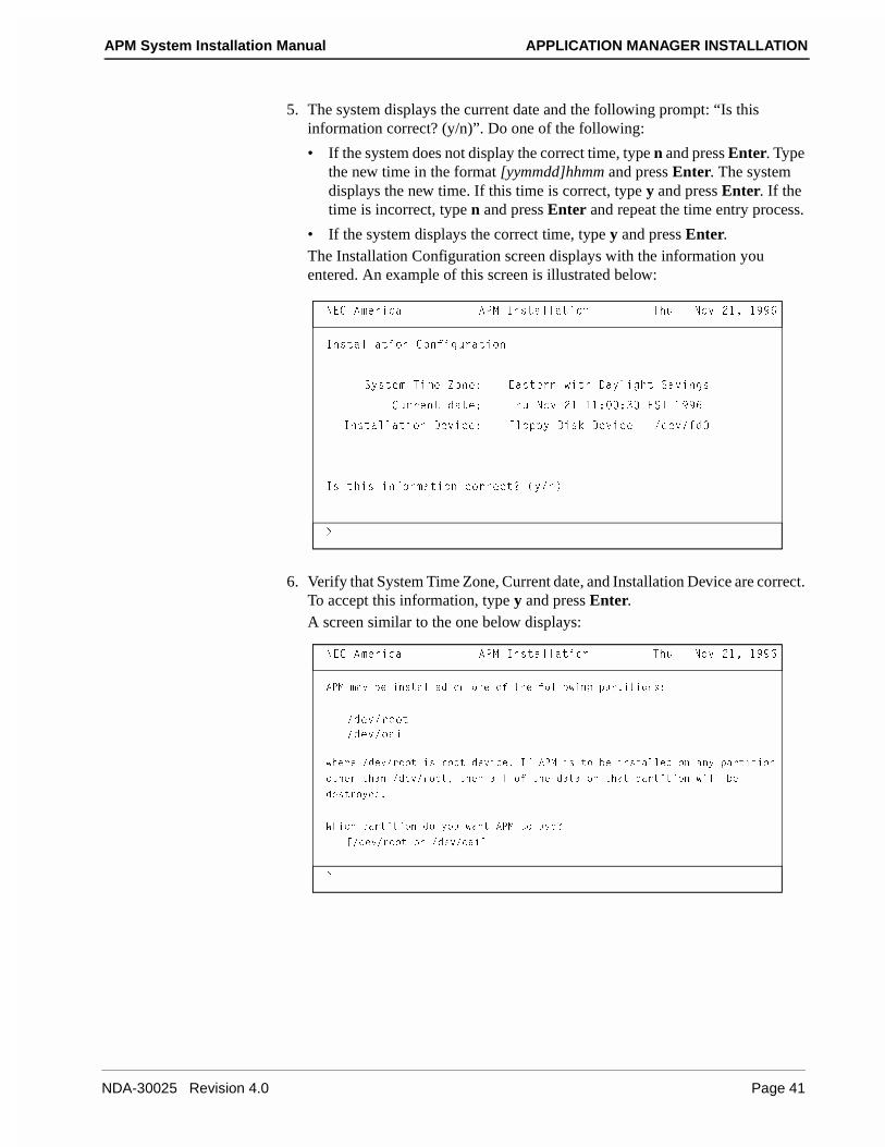
5. The system displays the current date and the following prompt: “Is this information correct? (y/n)”. Do one of the following:
• If the system does not display the correct time, type n and press Enter. Type the new time in the format [yymmdd]hhmm and press Enter. The system displays the new time. If this time is correct, type y and press Enter. If the time is incorrect, type n and press Enter and repeat the time entry process.
• If the system displays the correct time, type y and press Enter.The Installation Configuration screen displays with the information you entered. An example of this screen is illustrated below:
6. Verify that System Time Zone, Current date, and Installation Device are correct. To accept this information, type y and press Enter.A screen similar to the one below displays:
>53 1]UbYSQ 1@= 9^cdQ\\QdY_^ DXe � >_f "!� !))&
.
9^cdQ\\QdY_^ 3_^VYWebQdY_^
CicdU] DY]U J_^U* 5QcdUb^ gYdX 4Qi\YWXd CQfY^Wc
3ebbU^d TQdU* DXe >_f "! !!* *# 5CD !))&
9^cdQ\\QdY_^ 4UfYSU* 6\_``i 4Yc[ 4UfYSU � �TUf�VT
9c dXYc Y^V_b]QdY_^ S_bbUSd/ �i�^�
>53 1]UbYSQ 1@= 9^cdQ\\QdY_^ DXe � >_f "!� !))&
.
1@= ]Qi RU Y^cdQ\\UT _^ _^U _V dXU V_\\_gY^W `QbdYdY_^c*
�TUf�b__d
�TUf�_QY
gXUbU �TUf�b__d Yc b__d TUfYSU� 9V 1@= Yc d_ RU Y^cdQ\\UT _^ Q^i `QbdYdY_^
_dXUb dXQ^ �TUf�b__d� dXU^ Q\\ _V dXU TQdQ _^ dXQd `QbdYdY_^ gY\\ RU
TUcdb_iUT�
GXYSX `QbdYdY_^ T_ i_e gQ^d 1@= d_ ecU/
K�TUf�b__d _b �TUf�_QYM
NDA-30025 Revision 4.0 Page 41
APPLICATION MANAGER INSTALLATION APM System Installation Manual
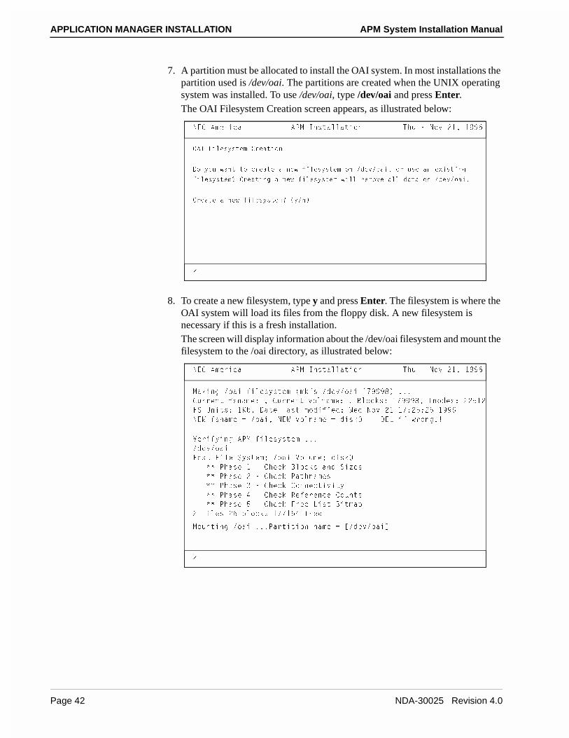
7. A partition must be allocated to install the OAI system. In most installations the partition used is /dev/oai. The partitions are created when the UNIX operating system was installed. To use /dev/oai, type /dev/oai and press Enter.The OAI Filesystem Creation screen appears, as illustrated below:
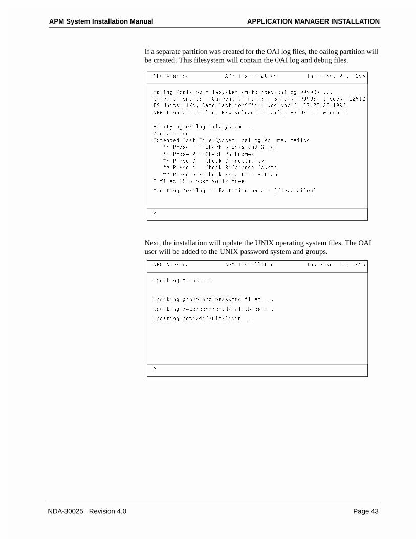
8. To create a new filesystem, type y and press Enter. The filesystem is where the OAI system will load its files from the floppy disk. A new filesystem is necessary if this is a fresh installation.The screen will display information about the /dev/oai filesystem and mount the filesystem to the /oai directory, as illustrated below:
>53 1]UbYSQ 1@= 9^cdQ\\QdY_^ DXe � >_f "!� !))&
.
?19 6Y\UcicdU] 3bUQdY_^
4_ i_e gQ^d d_ SbUQdU Q ^Ug VY\UcicdU] _^ �TUf�_QY� _b ecU Q^ UhYcdY^W
VY\UcicdU]/ 3bUQdY^W Q ^Ug VY\UcicdU] gY\\ bU]_fU Q\\ TQdQ _^ �TUf�_QY�
3bUQdU Q ^Ug VY\UcicdU]/ �i�^�
>53 1]UbYSQ 1@= 9^cdQ\\QdY_^ DXe � >_f "!� !))&
=Q[Y^W �_QY VY\UcicdU] �][Vc �TUf�_QY !')))(� ���
3ebbU^d Vc^Q]U* � 3ebbU^d f_\^Q]U* � 2\_S[c* !')))(� 9^_TUc* ""%!"
6C E^Ydc* !;R� 4QdU \Qcd ]_TYVYUT* GUT >_f "! !'*"%*"% !))&
>5G Vc^Q]U - �_QY� >5G f_\^Q]U - TYc[ �� 45< YV gb_^W��
FUbYViY^W 1@= VY\UcicdU] ���
�TUf�_QY
6Qcd 6Y\U CicdU]* �_QY F_\e]U* TYc[
�� @XQcU ! � 3XUS[ 2\_S[c Q^T CYjUc
�� @XQcU " � 3XUS[ @QdX^Q]Uc
�� @XQcU # � 3XUS[ 3_^^USdYfYdi
�� @XQcU $ � 3XUS[ BUVUbU^SU 3_e^dc
�� @XQcU % � 3XUS[ 6bUU <Ycd 2Yd]Q`
" VY\Uc "& R\_S[c !''!%$ VbUU
=_e^dY^W �_QY ���@QbdYdY_^ ^Q]U - K�TUf�_QYM
.
Page 42 NDA-30025 Revision 4.0
APM System Installation Manual APPLICATION MANAGER INSTALLATION
If a separate partition was created for the OAI log files, the oailog partition will be created. This filesystem will contain the OAI log and debug files.
Next, the installation will update the UNIX operating system files. The OAI user will be added to the UNIX password system and groups.
>53 1]UbYSQ 1@= 9^cdQ\\QdY_^ DXe � >_f "!� !))&
=Q[Y^W �_QY�\_W VY\UcicdU] �][Vc �TUf�_QY\_W ))))(� ���
3ebbU^d Vc^Q]U* � 3ebbU^d f_\^Q]U* � 2\_S[c* ))))(� 9^_TUc* !"%!"
6C E^Ydc* !;R� 4QdU \Qcd ]_TYVYUT* GUT >_f "! !'*"%*"% !))&
>5G Vc^Q]U - _QY\_W� >5G f_\^Q]U - _QY\_W �� 45< YV gb_^W��
FUbYViY^W _QY\_W VY\UcicdU] ���
�TUf�_QY\_W
5hdU^TUT 6Qcd 6Y\U CicdU]* _QY\_W F_\e]U* _QY\_W
�� @XQcU ! � 3XUS[ 2\_S[c Q^T CYjUc
�� @XQcU " � 3XUS[ @QdX^Q]Uc
�� @XQcU # � 3XUS[ 3_^^USdYfYdi
�� @XQcU $ � 3XUS[ BUVUbU^SU 3_e^dc
�� @XQcU % � 3XUS[ 6bUU <Ycd 2Yd]Q`
" VY\Uc !( R\_S[c )($!" VbUU
=_e^dY^W �_QY\_W ���@QbdYdY_^ ^Q]U - K�TUf�_QY\_WM
.
>53 1]UbYSQ 1@= 9^cdQ\\QdY_^ DXe � >_f "!� !))&
.
E`TQdY^W VcdQR ���
E`TQdY^W Wb_e` Q^T `Qccg_bT VY\Uc ���
E`TQdY^W �UdS�S_^V�SV�T�Y^Yd�RQcU ���
E`TQdY^W �UdS�TUVQe\d�\_WY^ ���
NDA-30025 Revision 4.0 Page 43
APPLICATION MANAGER INSTALLATION APM System Installation Manual
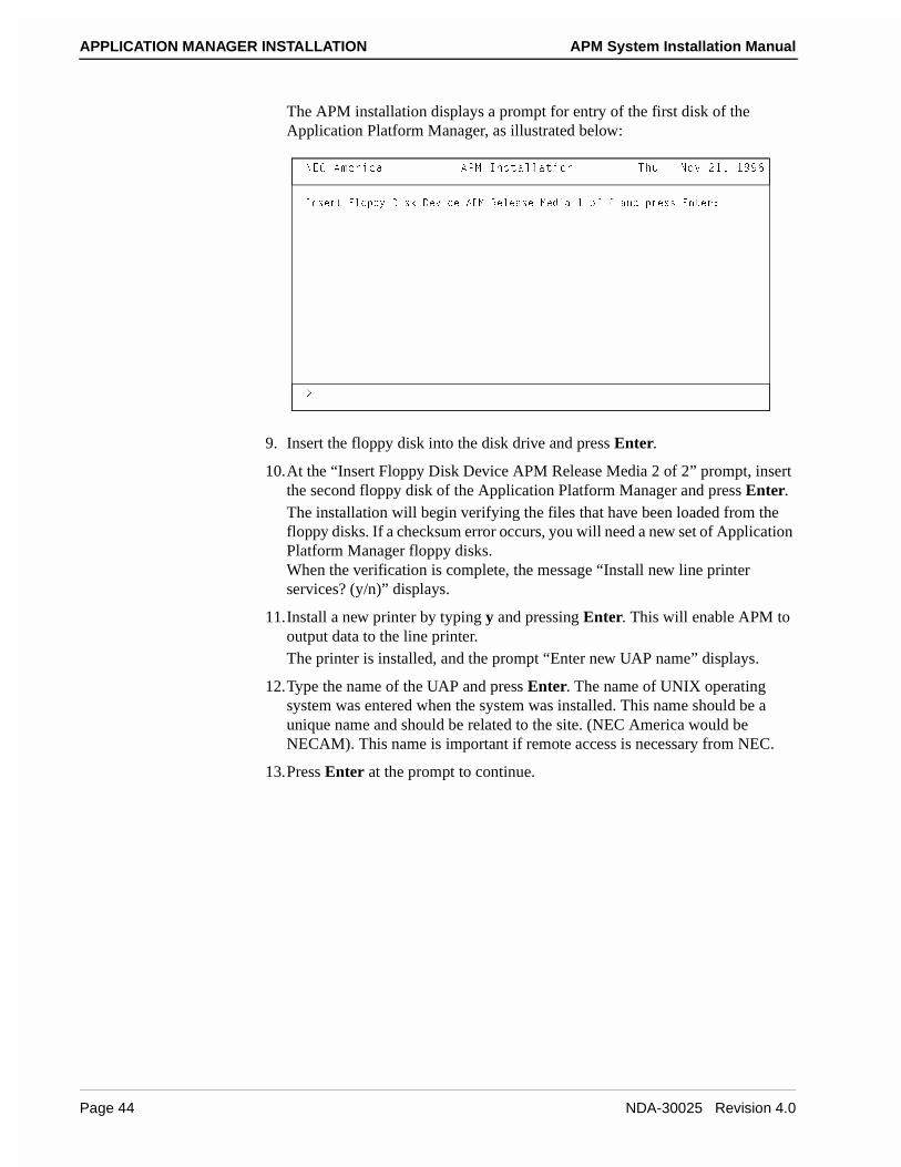
The APM installation displays a prompt for entry of the first disk of the Application Platform Manager, as illustrated below:
9. Insert the floppy disk into the disk drive and press Enter.
10.At the “Insert Floppy Disk Device APM Release Media 2 of 2” prompt, insert the second floppy disk of the Application Platform Manager and press Enter. The installation will begin verifying the files that have been loaded from the floppy disks. If a checksum error occurs, you will need a new set of Application Platform Manager floppy disks.When the verification is complete, the message “Install new line printer services? (y/n)” displays.
11.Install a new printer by typing y and pressing Enter. This will enable APM to output data to the line printer. The printer is installed, and the prompt “Enter new UAP name” displays.
12.Type the name of the UAP and press Enter. The name of UNIX operating system was entered when the system was installed. This name should be a unique name and should be related to the site. (NEC America would be NECAM). This name is important if remote access is necessary from NEC.
13.Press Enter at the prompt to continue.
9^cUbd 6\_``i 4Yc[ 4UfYSU 1@= BU\UQcU =UTYQ ! _V " Q^T `bUcc 5^dUb*
>53 1]UbYSQ 1@= 9^cdQ\\QdY_^ DXe � >_f "!� !))&
.
Page 44 NDA-30025 Revision 4.0
APM System Installation Manual APPLICATION MANAGER INSTALLATION
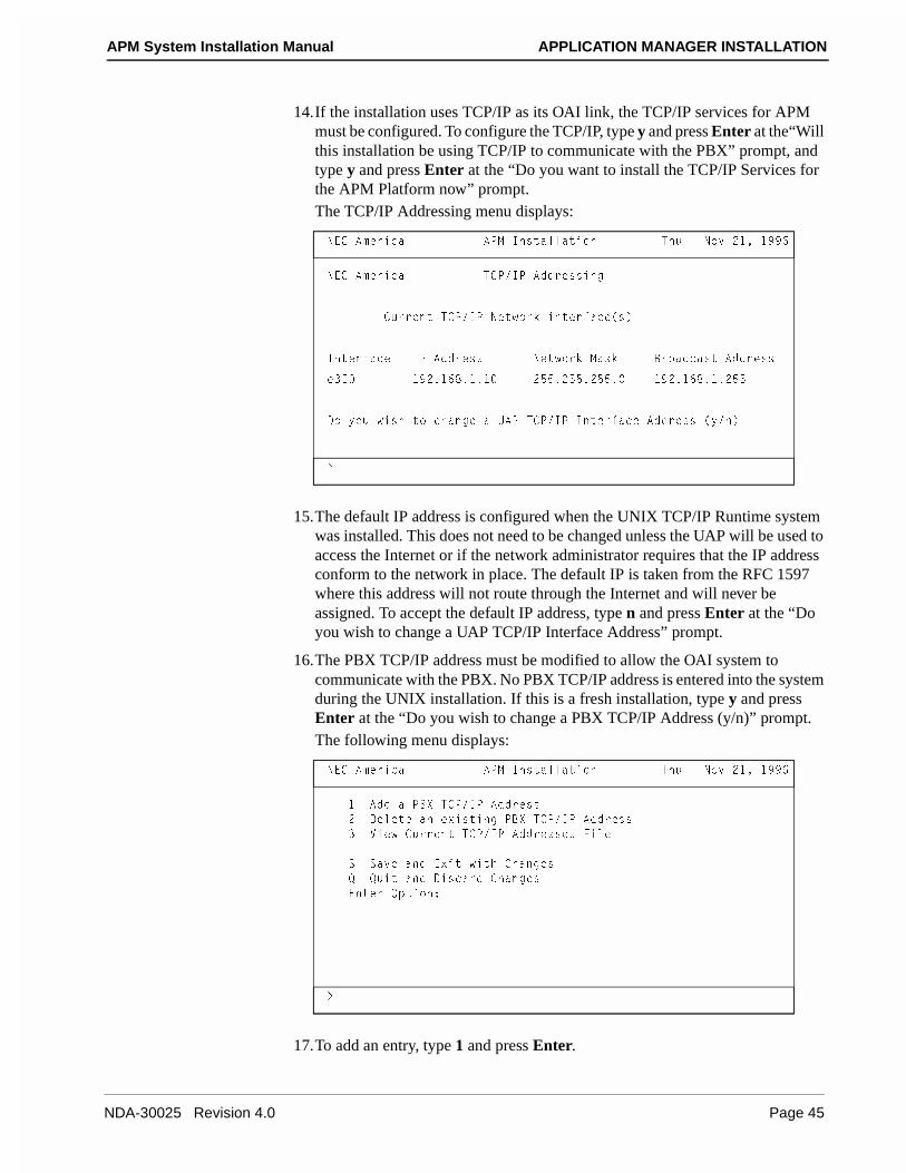
14.If the installation uses TCP/IP as its OAI link, the TCP/IP services for APM must be configured. To configure the TCP/IP, type y and press Enter at the“Will this installation be using TCP/IP to communicate with the PBX” prompt, and type y and press Enter at the “Do you want to install the TCP/IP Services for the APM Platform now” prompt.The TCP/IP Addressing menu displays:
15.The default IP address is configured when the UNIX TCP/IP Runtime system was installed. This does not need to be changed unless the UAP will be used to access the Internet or if the network administrator requires that the IP address conform to the network in place. The default IP is taken from the RFC 1597 where this address will not route through the Internet and will never be assigned. To accept the default IP address, type n and press Enter at the “Do you wish to change a UAP TCP/IP Interface Address” prompt.
16.The PBX TCP/IP address must be modified to allow the OAI system to communicate with the PBX. No PBX TCP/IP address is entered into the system during the UNIX installation. If this is a fresh installation, type y and press Enter at the “Do you wish to change a PBX TCP/IP Address (y/n)” prompt.The following menu displays:
17.To add an entry, type 1 and press Enter.
>53 1]UbYSQ 1@= 9^cdQ\\QdY_^ DXe � >_f "!� !))&
.
>53 1]UbYSQ D3@�9@ 1TTbUccY^W
3ebbU^d D3@�9@ >Udg_b[ Y^dUbVQSU�c�
9^dUbVQSU 9@ 1TTbUcc >Udg_b[ =Qc[ 2b_QTSQcd 1TTbUcc
U#5 !)"�!&(�!�! "%%�"%%�"%%� !)"�!&(�!�"%%
4_ i_e gYcX d_ SXQ^WU Q E1@ D3@�9@ 9^dUbVQSU 1TTbUcc �i�^�
>53 1]UbYSQ 1@= 9^cdQ\\QdY_^ DXe � >_f "!� !))&
.
! 1TT Q @2H D3@�9@ 1TTbUcc
" 4U\UdU Q^ UhYcdY^W @2H D3@�9@ 1TTbUcc
# FYUg 3ebbU^d D3@�9@ 1TTbUccUc 6Y\U
C CQfU Q^T 5hYd gYdX 3XQ^WUc
A AeYd Q^T 4YcSQbT 3XQ^WUc
5^dUb ?`dY_^*
NDA-30025 Revision 4.0 Page 45

APPLICATION MANAGER INSTALLATION APM System Installation Manual
18.Type the host name of the PBX and press Enter.
19.Type the PBX TCP/IP address and press Enter.
20.If the host name and TCP/IP address are correct, type y and press Enter.The menu redisplays.
21.Type s and press Enter to save the PBX address and exit.The following screen appears:
22.The IP addresses will be updated in the /etc/hosts file. After the installation has completed, the OAI links must be configured by the Application Platform Manager. Press Enter to continue.
23.The message “Do you wish to install the modem scripts and update the uucp files” displays. Type y and press Enter to install and program the modem that will be used for remote access.
24.The modems are normally attached to COM1 of the PC. The device that is associated with COM1 is /dev/tty1A. This option will program the modem with default values that correspond to modems used at NEC. The modem will be used for remote access in case a problem occurs. Type /dev/tty1A and press Enter when the following message displays: “Enter tty device attached to modem [/dev/tty1A]”.Information displays as the modem is being programmed, as illustrated below:
>53 1]UbYSQ 1@= 9^cdQ\\QdY_^ DXe � >_f "!� !))&
.
�UdS�X_cdc VY\U e`TQdUT
C_ebSU <Y^[ >_TUc Q^T 4UcdY^QdY_^ <Y^[ >_TUc ]ecd RU cUde` dXQd c`USYVi
dXU @2H X_cd^Q]U U^dbYUc� DXYc Yc T_^U Vb_] dXU 1``\YSQdY_^c =Q^Q^WUb �1@=�
Ri cU\USdY^W dXU �CicdU] 3_^VYWebQdY_^� U^dbi Y^ CicdU] 1T]Y^cdbQdY_^ ]U^e
Q^T dXU^ V_\\_gUT Ri cU\USdY^W dXU �C_ebSU <Y^[ 3_^VYWebQdY_^� Q^T
�4UcdY^QdY_^ <Y^[ 3_^VYWebQdY_^� ]U^ec� 6_b ]_bU Y^V_b]QdY_^ bUVUb d_ dXU
C_ebSU�4UcdY^QdY_^ <Y^[ 3_^VYWebQdY_^ cUSdY_^c Y^ dXU 1@=
?`UbQdY_^c =Q^eQ\�
@bUcc BUdeb^ d_ S_^dY^eU
Page 46 NDA-30025 Revision 4.0

APM System Installation Manual APPLICATION MANAGER INSTALLATION
25.Press Enter to continue.Modifications made to the UNIX operating system will require the operating system to relink. The UNIX operating system will relink and create a new operating system.
26.At this point in the installation, a new UNIX operating system is recreated. Type y and press Enter at the “Do you want this kernel to boot by default?” prompt. This kernel will be the default when the system boots.
27.Rebuild the kernel environment by typing y and pressing Enter at the “Do you want the kernel environment rebuilt?” prompt. The following screen displays:
>53 1]UbYSQ 1@= 9^cdQ\\QdY_^ DXe � >_f "!� !))&
.
��� 4YcQR\U �TUf�ddi!1 ���
��� E`TQdY^W �ecb�\YR�eeS`�4UfYSUc gYdX 13E ddi!1 ���
��� E`TQdY^W �ecb�\YR�eeS`�4UfYSUc gYdX ddi!1 ���
��� E`TQdY^W �ecb�\YR�eeS`�4YQ\Ubc gYdX EC B_R_dYSc =_TU] ���
��� E`TQdY^W �ecb�\YR�eeS`�@Ub]YccY_^c V_b 4YQ\�Y^ ���
��� E`TQdY^W �UdS�WUddiTUVc gYdX !)" ?><I ���
��� E`TQdU �TUf�ddi!1 Y^ �UdS�Y^YddQR d_ !)" RQeT �[� ���
�. CU!1*"*_VV*�UdS�WUddi �d& ddi!1 #
��� E`TQdU �TUf�ddi!1 Y^ �UdS�S_^V�Y^Yd�T�cY_ d_ !)" RQeT �[� ���
�. CU!1*"*_VV*�UdS�WUddi �d& ddi!1 #
��� 5^QR\U �TUf�ddi!1 ���
�UdS�Y^YddQR e`TQdUT
�UdS�S_^V�Y^Yd�T�cY_ e`TQdUT
@bUcc bUdeb^
>53 1]UbYSQ 1@= 9^cdQ\\QdY_^ DXe � >_f "!� !))&
.
E^]_e^dY^W �TUf�_QY ���
DXU 1@= @\QdV_b] XQc RUU^ ceSSUccVe\\i Y^cdQ\\UT�
���������������������������������������������������������������
BU]_fU bU\UQcU ]UTYQ Vb_] 6\_``i 4Yc[ 4UfYSU RUV_bU bUR__dY^W�
���������������������������������������������������������������
@bUcc 5^dUb d_ S_^dY^eU
NDA-30025 Revision 4.0 Page 47

APPLICATION MANAGER INSTALLATION APM System Installation Manual
28.After the new UNIX operating system has been created, it is necessary to reboot the system and load the new UNIX operating system. Press Enter to shut down the operating system.The installation will continue the shut down until the following screen appears:
29. To reboot the system press Enter.After the system has rebooted and enters multi-user mode, the Application Platform Manager login displays, as illustrated below. For more information about the operation of the Application Platform Manager consult the Application Platform Manager Operations Manual.
9>9D* >Ug be^ \UfU\*
DXU cicdU] Yc S_]Y^W T_g^� @\UQcU gQYd�
CicdU] cUbfYSUc QbU ^_g RUY^W cd_``UT�
`c* �e^Yh* ^_d dXU R__dUT cicdU]
@bY^d cUbfYSUc cd_``UT�
D3@ CXedT_g^���
Cd_``Y^W D3@�9@ TQU]_^c���
������
D3@ CXedT_g^ 3_]`\UdU�
DXU cicdU] Yc T_g^�
�� CQVU d_ @_gUb ?VV ��
�_b�
�� @bUcc 1^i ;Ui d_ BUR__d ��
1``\YSQdY_^ =Q^QWUb DXe � >_f "!� !))&
��� >53 @b_`bYUdQbi ���
5^dUb @Qccg_bT*
,B5D. d_ QSSU`d `Qccg_bT� ,5C3. d_ aeYd
Page 48 NDA-30025 Revision 4.0

APM System Installation Manual BACKUP AND RESTORATION PROCEDURES
Chapter 5 BACKUP AND RESTORATION PROCEDURES
Creating Boot and Root Floppy Disks
SCO recommends the creation of an Emergency Boot Floppy set after installation. This is the only means of attempting recovery of the root filesystem or the kernel in the event that problems occur.
To create a boot and root floppy disks follow the procedure below:
1. At the “#” prompt, type mkdev fd and press Enter.The following screen appears:
2. Type 4 and press Enter.The following screen appears:
3. Type 2 and press Enter.
4. Insert a 135ds18 floppy disk into the disk drive, and press Enter.
5. At the “Would you like to format the floppy disk first? (y/n) prompt, type n and press Enter.The bootable floppy is created, and the following screen appears:
6. Type 3 and press Enter.
6\_``i 4Yc[ 6Y\UcicdU] 3bUQdY_^ @b_WbQ]
3X_YSUc V_b di`U _V V\_``i VY\UcicdU]�
!� $(d`Y� T_eR\U cYTUT� ) cUSd_bc `Ub dbQS[
"� )&d`Y� T_eR\U cYTUT� !% cUSd_bc `Ub dbQS[
#� !#%d`Y� T_eR\U cYTUT� ) cUSd_bc `Ub dbQS[
$� !#%d`Y� T_eR\U cYTUT� !( cUSd_bc `Ub dbQS[
5^dUb Q^ _`dY_^ _b a d_ aeYd*
3X_YSUc V_b S_^dU^dc _V V\_``i VY\UcicdU]�
!� 6Y\UcicdU]
"� 2__dQR\U _^\i �)&Tc!% Q^T !#%Tc!( _^\i�
#� B__d VY\UcicdU] _^\i �)&Tc!% Q^T !#%Tc!( _^\i�
5^dUb Q^ _`dY_^ _b a d_ aeYd*
3X_YSUc V_b S_^dU^dc _V V\_``i VY\UcicdU]�
!� 6Y\UcicdU]
"� 2__dQR\U _^\i �)&Tc!% Q^T !#%Tc!( _^\i�
#� B__d VY\UcicdU] _^\i �)&Tc!% Q^T !#%Tc!( _^\i�
5^dUb Q^ _`dY_^ _b a d_ aeYd*
NDA-30025 Revision 4.0 Page 49

BACKUP AND RESTORATION PROCEDURES APM System Installation Manual
7. Insert a 135ds18 floppy disk into the disk drive, and press Enter.
8. At the “Would you like to format the floppy disk first? (y/n) prompt, type n and press Enter.The filesystem floppy is created, and the menu reappears.
9. Exit the menu by typing q and pressing Enter.
Tape Backup and Restore
The UAP system must be backed up prior to making any changes to the system. This will ensure that the system can always be restored to initial configuration in the event of hard disk corruption or failure. Both the tape backup and restore rely on a valid boot and root floppy disks. Two sets of the boot and root floppies should be made with one set reserved for backup with the write protect tab set to write protected.
Note: Before using the root floppy the write protect should be set to unprotected.
Another backup should be made after the final configured system and applications have been completed.
Backup For OAI applications that use INFORMIX software for databases, the INFORMIX databases must be backed up using the INFORMIX utilities. Refer to the application documentation for specific instructions.
To backup the UAP, use the following steps.
Step 1: Record Partition Table InformationThe partition table must be recorded from the hard disk in case there is a hard disk failure. Information in the partition table will vary according to the size of the hard disk. Record this information and store it with the root and boot floppy disks. To list the values of the partition table enter the following commands:
1. At the login prompt, type root and press Enter.
2. Type the root password, and press Enter.
3. At the “#” prompt, type divvy and press Enter.The partition table displays and is similar to the table below:
4. Record the information for future use.
Name Type New FS # First Block Last Block
b__d 516C iUc )))))
cgQ` >?> 6C ^_ ! ! !&#)))
_QY 516C iUc " !&$ "&#)))
_QY\_W 516C iUc # "&$ #&#)))
TR >?D EC54 ^_ $ #&$ (&#)))
>?D EC54 ^_ % � �
bUS_fUb >?> 6C ^_ & ! # !&% ! # !'$
T! %'Q\\ G8?<5 49C; ^_ ' ! #!!%"
Page 50 NDA-30025 Revision 4.0

APM System Installation Manual BACKUP AND RESTORATION PROCEDURES
5. After you have recorded the information, exit the menu by typing q and pressing Enter.The following screen displays:
6. Type e and press Enter.The “#” prompt displays.
7. Type exit and press Enter.
Step 2: Boot the System from the Boot and Root FloppiesIn order to backup the UAP, the system must be loaded from the boot and root floppies. If the system was loaded from the hard disk, it must be shut down so it can be loaded from the boot and root floppies. Perform the following steps to shutdown the system and boot it from the boot and root flopppies:
1. Terminate any initialized OAI applications and stop OAI if it has been active.
2. Exit from Application Manager (APM).
3. At the login prompt, type root and press Enter.
4. When the password prompt displays, type the root password and press Enter.
5. At the “#” prompt, type shutdown -g0 -i0 -y and press Enter.The system shuts down.
6. When the system displays the “Safe to Power Off” prompt, insert the boot floppy and press Enter.
7. When the “Boot:” prompt displays, press Enter.The UAP boots from the boot floppy and displays a prompt for the root floppy.
8. Insert the root floppy press Enter.When the system is loaded, the “#” prompt displays.
Note: Do not remove the root floppy until you shut down the system.
Step 3: Backup the UAPAfter you have booted the system from the boot and root floppies, use the following steps to backup the UAP:
1. Insert a tape into the tape drive.
2. To backup the different filesystems, each filesystem must be mounted. Type the following commands at the “#” prompt, pressing Enter after each:
(a) # mount /dev/hd0root /mnt
(b) # mount /mnt/dev/oai /mnt/oai
(c) # mount /mnt/dev/oailog /mnt/oai/log
YK^cdQ\\M 9^cdQ\\ dXU TYfYcY_^ cUd�e` cX_g^
bKUdeb^M BUdeb^ d_ dXU `bUfY_ec ]U^e
UkhYdm 5hYd gYdX_ed Y^cdQ\\Y^W Q TYfYcY_^ dQR\U
NDA-30025 Revision 4.0 Page 51
BACKUP AND RESTORATION PROCEDURES APM System Installation Manual
3. To save the drive parameters, fdisk partition information and divvy information on the root floppy and hard drive so that they can be viewed during the recovery procedure. Run the following commands pressing Enter after each line:
(a) # dparam /dev/rhd00 > /dkinit.sav
(b) # dparam /dev/rhd00 > /mnt/dkinit.sav
(c) # fdisk -p > /fdisk.sav
(d) # fdisk -p > /mnt/fdisk.sav
(e) # divvy > /divvy.savqe
(f) # divvy > /mnt/divvy.savqe
4. To begin the backup type the following commands at the “#” prompt, pressing Enter after each command. The -K525000 indicates the tape has 525000 1K blocks (525 Megabytes) . If your tape is of a different size, then change the block count accordingly. The /dev/rStp0 value specifies the tape device. If you are using a different tape device, then change the name accordingly.
(a) # cd /mnt
(b) # find . -depth -print | cpio -ocvB -C10240 -K525000 > /dev/rStp0
5. When the “#” prompt displays, the backup has finished. Remove the tape and label the tape UAP Backup and provide the current date.
6. To complete the backup procedure, the filesystem must be unmounted and the system shutdown. To perform this procedure type the following commands at the “#” prompt, pressing Enter after each:
(a) # cd /
(b) # umount /mnt/dev/oailog
(c) # umount /mnt/dev/oai
(d) # umount /mnt
7. To verify the data on the tape, type cpio -itv < /dev/rStp0 and press Enter.The file names stored on the tape and total block count display.
8. To shutdown the system, type the following commands at the “#” prompt, pressing Enter after each:
(a) # sync
(b) # sync
(c) # haltsys
9. When the following “Safe to Power Off” prompt displays, remove the root floppy and press Enter to boot from the hard disk.
Page 52 NDA-30025 Revision 4.0

APM System Installation Manual BACKUP AND RESTORATION PROCEDURES
Restore Use the following steps to restore the UAP:
Step 1: Boot the UAP from the Boot and Root FloppiesIn order to restore the UAP, the system must be loaded from the boot and root floppies. If the system was loaded from the hard disk, it must be shut down so it can be loaded from the boot and root floppies. For information on booting from the boot and root floppies, see “Step 2: Boot the System from the Boot and Root Floppies” on page 51.
Step 2: Procedures for a New or Reformatted Hard DriveIf the system has not been severely corrupted or damaged and you want to use the filesystem as it is but you need to restore the files back to their original state, go to “Restore the UAP” on page 56.
If the system has been severely corrupted or damaged, the drive should be reformatted (or possibly replaced). Use the instructions from the drive manufacturer to reformat the drive as needed. Then use the following procedures to setup the disk for restore.
1. You must set the correct drive parameters, fdisk partition information and divvy partition information for the hard drive. If the backup procedures were followed the following 3 commands can be typed to view the drive parameters, fdisk parition information and divvy partition information respectively that were saved on the root floppy.
(a) # cat /dkinit.sav
(b) # cat /fisk.sav
(c) # cat /divvy.savThis data should be written down so that the data can be entered as needed in later steps of this Restore Procedure.
2. If the drive must have it’s cylinders, head, and sectors/track adjusted, type dkinit /dev/rhd00 and press Enter.
8QbT 4Yc[ 4bYfU 3_^VYWebQdY_^
!� 4Yc`\Qi SebbU^d TYc[ `QbQ]UdUbc
"� =_TYVi SebbU^d TYc[ `QbQ]UdUbc
#� CU\USd TUVQe\d TYc[ `QbQ]UdUbc
5^dUb i_eb SX_YSU _b a d_ aeYd*
NDA-30025 Revision 4.0 Page 53

BACKUP AND RESTORATION PROCEDURES APM System Installation Manual
3. Type 1 and press Enter.The drive's parameters display. For a typical 1 Gigabyte hard drive, the parameter table would contain the following values:
Disk Parameters Values1. Cylinders 20472. Heads 163. Write Reduce 04. Write Precomp 05. Ecc 06. Control 87. Landing Zone 20488. Sectors/track 63
Note: The number of cylinders, sectors, and heads varies from disk to disk. These may need to be modified depending on the hard disk installed.
4. If the parameters are not correct, select option 2 (Modify current disk parameters) and press Enter.
5. Type the number associated with the incorrect value and press Enter.
6. At the prompt, enter the replacement value and press Enter.
7. Continue this process until all values are correct, and display the parameters by typing 1 and pressing Enter at the Hard Disk Drive 0 Configuration menu.
8. If the values are correct, exit the menu by typing q and pressing Enter.
9. Enter the following command to stamp the disk geometry onto the hard disk.# dparam /dev/rhd00 ‘dparam /dev/rhd00‘
Note: The quotes in the above dparam command are back quotes which are located in the top left corner of the keyboard on most keyboards .
10.At the “#” prompt type fdisk and press Enter.The fdisk program will display a menu of selections.
11.Setup a UNIX partition as needed. If the backup procedures were followed the cat /fdisk.sav command of step 1 shows the original fdisk values used. For most installations, the entire disk is used for UNIX and therefore the 2 option can be used to use the entire disk for UNIX.
12.Type q and press Enter to exit the fdisk command.
13.At the “#” prompt, type divvy -i and press Enter.The following message displays: “Please enter the swap-space allocation, or press <Return> to get the default allocation of 15000 1K blocks.”
14.Press Enter.The following message displays: “Do you want a separate /u filesystem? (y/n)”
Page 54 NDA-30025 Revision 4.0

APM System Installation Manual BACKUP AND RESTORATION PROCEDURES
15.Type n and press Enter.The following message displays: “Do you wish to make any manual adjustments to the sizes or names of the filesystems or swap area before they are created on the hard disk? (y/n)”.
16.Type y and press Enter.
17.The the divvy table will displayed. The table will list the divisions (0 thru 7) on the hard disk and the names of each partition. The root, swap, recover, and hd0a divisions will be listed. The oai, oailog, and db divisions will need to be named. The first and last blocks for each division will need to be modified and new filesystems created for oai and oailog partitions. This information is found in the partition table that was recorded in the backup procedure and displayed from the cat /divvy.sav comand in step 1. Refer to “Step 11: Make Manual Adjustments to the Filesystems” on page 16 for information on updating the partition table.
18.After the table has been modified, type q and press Enter.The following menu displays:
19.To install the new divvy table enter, type i and press Enter.The filesystems will then be installed on the hard disk.
20.To update the boot loader on the hard disk, type the following commands at the “#” prompt, pressing Enter after each:
(a) dd if=/etc/hdboot0 of=/dev/hd0a
(b) dd if=/etc/hdboot1 of=/dev/hd0a bs=1k seek=1
YK^cdQ\\M 9^cdQ\\ dXU TYfYcY_^ cUd�e` cX_g^
bKUdeb^M BUdeb^ d_ dXU `bUfY_ec ]U^e
NDA-30025 Revision 4.0 Page 55

BACKUP AND RESTORATION PROCEDURES APM System Installation Manual
Step 3: Restore the UAP
1. Insert a tape into the tape drive.
2. To restore the different filesystem, the root filesystem must be mounted first and restored. Type the following commands at the “#” prompt, pressing Enter after each:
(a) mount /dev/hd0root /mnt
(b) cd /mnt
(c) cpio -icvmadu “[!o]*” < /dev/rStp0
3. Once the root partition has been restored, the OAI and OAILOG filesystem will be restored. To restore the filesystems, type the following commands at the “#” prompt, pressing Enter after each:
(a) /mnt/bin/mkdir /mnt/oai
(b) mount /mnt/dev/oai /mnt/oai
(c) /mnt/bin/mkdir /mnt/oai/log
(d) mount /mnt/dev/oailog /mnt/oai/log
(e) cd /mnt
(f) cpio -icvmadu “o*” < /dev/rStp0
4. To complete the restore procedure, the filesystem must be unmounted and the system shutdown. To perform this procedure, type the following commands at the “#” prompt, pressing Enter after each:
(a) cd /
(b) umount /mnt/dev/oailog
(c) umount /mnt/dev/oai
(d) umount /mnt
5. To shutdown the system, type the following commands at the “#” prompt, pressing Enter after each:
(a) sync
(b) sync
(c) haltsys
6. When the following “Safe to Power Off” prompt displays, remove the root floppy and press Enter to boot from the hard disk.
Page 56 NDA-30025 Revision 4.0

APM System Installation Manual TROUBLESHOOTING ISSUES
Chapter 6 TROUBLESHOOTING ISSUES
This chapter addresses some general-system issues that may cause an installation attempt to fail or to produce unpredictable results. If problems occur during installation, review the relevant chapter in this manual and verify that you have performed the procedures accurately, making sure that you have conducted the recommended testing procedures successfully. Then, review the troubleshooting issues discussed in this chapter. If the problem is still not resolved, consult the system distributor.
TCP/IP Connectivity to PBX
If the applications are unable to connect to the PBX, the problem could be that Ethernet connection to the PBX is not operating properly. To test for Ethernet connectivity perform the following:
Step 1: “ping” for Localhost ConnectivityThe “ping” test verifies the network driver communication with the Ethernet card. The following example shows the use of this command to send 3 ICMP packets of 1024 bytes in length to the local network card:
1. At the “#” prompt, type ping -s 1024 -c 3 and press Enter.The following screen displays:
2. In the example above, the message “3 packets transmitted, 3 packets received, 0% packet loss” indicates that the TCP/IP device drivers are operating properly. If the transmission was unsuccessful, consult the SCO TCP/IP Runtime System documentation and reinstall TCP/IP.
�`Y^W \_SQ\X_cd ! "$#
@9>7 \_SQ\X_cd* ! "$ TQdQ RidUc
! #" RidUc Vb_] !"'� � �!* YS]`OcUa- � dY]U-!&� ]c
! #" RidUc Vb_] !"'� � �!* YS]`OcUa-!� dY]U- �]c
! #" RidUc Vb_] !"'� � �!* YS]`OcUa-"� dY]U- � ]c
����\_SQ\X_cd @9>7 CdQdYcdYSc����
# `QS[Udc dbQ^c]YddUT� # `QS[Udc bUSUYfUT� � `QS[Ud \_cc
b_e^T�dbY` �]c� ]Y^�QfW�]Qh - �%�!&
NDA-30025 Revision 4.0 Page 57

TROUBLESHOOTING ISSUES APM System Installation Manual
Step 2: “netstat”At the “#” prompt, issue the netstat command, as illustrated below. This command shows the state of the interfaces that have been configured into the system.
Step 3: “ping” for Remote Host ConnectivityAfter successfully testing the “localhost” communications, use the “ping” command to verify that the connectivity of other network hosts is available.
1. At the “#” prompt, type the ping command using the following format:#ping othermachine1 -s 1024 -c 3
2. If this test is unsuccessful, perform the following verifications and refer to the SCO UNIX documentation for further troubleshooting instructions:
(a) Ensure the correct IP address is stored in the “/etc/hosts” for the othermachine1 host.
(b) Ensure the actual target machine is operating correctly on the network.
16 Mbyte RAM
If SCO UNIX is being installed onto a system with 16 Mbytes of RAM, it may be necessary to use a special NEC version of the “N1” installation disk. If this disk is needed, contact NEC Technologies for instructions on obtaining one.
�^UdcdQd �Y
>Q]U =de >Udg_b[ 1TTbUcc 9`[dc 9Ubbc ?`[dc ?Ubbc 3_\\U#2 !% !!!�"""�###�$$$ ]i]QSXY^U !%%((( %' ! ')% #% '!_ " $( \__`RQS[ \_SQ\X_cd (((%& (((%&
Page 58 NDA-30025 Revision 4.0
APM System Installation Manual TROUBLESHOOTING ISSUES
COM Port Usage
The typical UAP does not require use of the COM1 and COM2 serial I/O ports for OAI-related input. Generally the COM2 port which is assigned to Interrupt Request (IRQ) 3 will be disabled so that other communication devices to be installed later can use this address. Consult the CPU technical documentation to isolate the location of the correct switch settings often found on the mother board itself.
A TCP/IP Ethernet card is a good candidate for using IRQ 3 or IRQ 5. If IRQ 3 is chosen without first disabling the COM2 port on the mother board, unpredictable results may occur when testing the card. To prevent unpredictable results, consult the system manual for information on disabling the COM2 port. Typically this is done through the BIOS setup.
Note: Disabling the COM2 port does not affect the operation of the COM1 port, which remains available for attaching a mouse or other desired device. If the UAP does not have a tape backup system installed, use IRQ 5.
Video Adapter Addressing
Most VGA video adapters operate in either an 8- or 16-bit mode. Consult manufacturer documentation for all of the peripherals that must be installed if the video card is to be operated in a 16-bit mode. In some systems, this causes a conflict when installing other 8-bit device controllers, making the outcome unpredictable at best.
During the hardware “setup” it would be wise to disable RAM Video Shadowing since it often conflicts with memory address ranges that are needed by other required devices.
Root File System Recovery
To restore a kernel or to check the root filesystem when having problems with the system, refer to Chapter 5, “BACKUP AND RESTORATION PROCEDURES”.
NDA-30025 Revision 4.0 Page 59

TROUBLESHOOTING ISSUES APM System Installation Manual
This Page Left Blank.
Page 60 NDA-30025 Revision 4.0